LENNOX Air Conditioner/heat Pump(outside Unit) Manual L0806490
User Manual: LENNOX LENNOX Air conditioner/heat pump(outside unit) Manual LENNOX Air conditioner/heat pump(outside unit) Owner's Manual, LENNOX Air conditioner/heat pump(outside unit) installation guides
Open the PDF directly: View PDF ![]() .
.
Page Count: 18
LENNOX
_2003 Lennox industries inc.
Dallas, Texas, USA
INSTALLATION
INSTRUCTIONS
HP29 Heat Pump Units
HEAT PUMP UNITS
1-1/2 through 5 tons q [_ _ Technical
504,829M J L [ Publications
06/04 Litho U.S.A.
Supersedes 02/04
Lennox Elite® Series HP29 outdoor units are approved
and warranted only for installation with specially
matched indoor coils, line sets, and refrigerant control
devices as designated by Lennox. Refer to Lennox engi-
neering hand book for expansion valve kits which must be
ordered separately.
1 - Assembled HP29 outdoor unit
1 - Coupling, 5/16 x 3/8" (018, 024, 030)
Check equipment for shipping damage. If you find any
damage, immediately contact the last carrier.
a,WARNING
IMPORTANT
HP29 Outdoor Units ............................ 1
Shipping & Packing List ......................... 1
General Information ............................ 1
Unit Dimensions ............................... 2
Setting the Unit ................................ 3
Electrical ...................................... 4
Refrigerant Piping .............................. 5
Refrigerant Metering Device ..................... 9
Manifold Gauge Set ............................ 9
Service Valves ................................ 10
Leak Testing .................................. 11
Evacuation ................................... 12
Start-Up ...................................... 13
Charging ..................................... 13
System Operation ............................. 15
Defrost System ............................... 15
Optional Units ................................ 17
Maintenance .................................. 17
Optional Accessories .......................... 17
Start-Up and Performance Check List ............ 18
RETAIN THESE INSTRUCTIONS
FOR FUTURE REFERENCE
These instructions are intended as a general guide and do
not supersede national or local codes in any way. Authorities
having jurisdiction should be consulted before installation.
A WARNING
06/04
IIIHIIIIIIIIIIIHIIII]IIII]IIIIIIII Page 1 504,829M
IIIllllll]lllllllllllll]llll]llll]llllllllllll
inlet
©
air
inlet,_air
inlet"_air
Top View
inlet
©
air
4-3/8
(111)
optional unit _
stand-off kit (4)
(field-installed)
coil drain outlets _lm
(around perimeter of base) •
vapor line
connection
liquid line
connection
6-3/8
(162)
Top View Base Section
ql -m C
Side View
°i T'
B A
(19)
electrical
inlets
outdoor
coil fan
compressor
vapor &
liquidline
connecti
2-3/4 (70)
optional unit J
stand-off kit (4)
(field-installed)
AIR
c ;
I
Side View
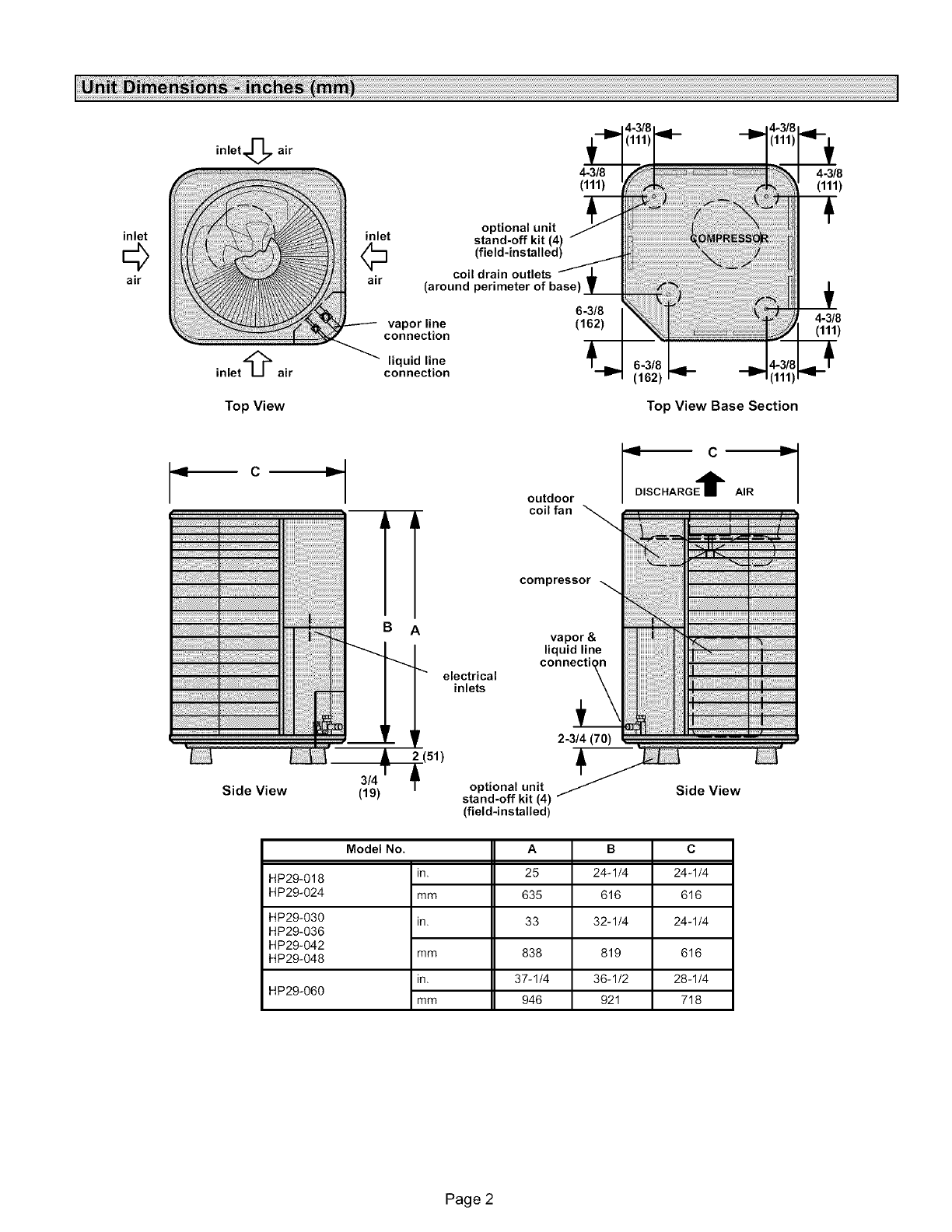
HP29-018
HP29-024
HP29-030
HP29-036
HP29-042
HP29-048
HP29-060
Model No.
in.
mm
in.
mm
in.
mm
A
25
635
33
838
37-1/4
946
B
24-1/4
616
32-1/4
819
36-1/2
921
C
24 -1/4
616
24 -1/4
616
28-1/4
718
Page 2
-&CAUTION
ACAUTION
These units operate under a wide range of weather condi-
tions; therefore, several factors must be considered when
positioning the outdoor unit. The unit must be positioned to
give adequate clearances for sufficient airflow and servic-
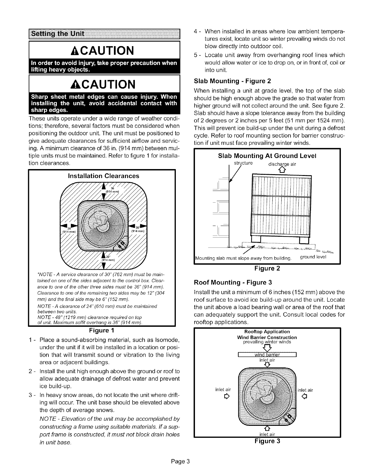
ing. A minimum clearance of 36 in. (914 mm) between mul-
tiple units must be maintained. Refer to figure 1 for installa-
tion clearances.
Installation Clearances
_
_
_
*NOTE - A service clearance of 30" (762 mm) must be main-
tained on one of the sides adjacent to the control box. Clear-
ance to one of the other three sides must be 36" (914 mm).
Clearance to one of the remaining two sides may be 12" (304
mm) and the final side may be 6" (152 mm).
NO TE -Aclearance of 24" (610 mm) must be maintained
between two units.
NOTE -48" (1219 mm) clearance required on top
of unit. Maximum soffit overhang is 36" (914 mm).
Figure 1
Place a sound-absorbing material, such as Isomode,
under the unit if it will be installed in a location or posi-
tion that will transmit sound or vibration to the living
area or adjacent buildings.
Install the unit high enough above the ground or roof to
allow adequate drainage of defrost water and prevent
ice build-up.
In heavy snow areas, do not locate the unit where drift-
ing will occur. The unit base should be elevated above
the depth of average snows.
NOTE- Elevation of the unit may be accomplished by
constructing a frame using suitable materials. Ira sup-
port frame is constructed, it must not block drain holes
in unit base.
4 - When installed in areas where low ambient tempera-
tures exist, locate unit so winter prevailing winds do not
blow directly into outdoor coil.
5 - Locate unit away from overhanging roof lines which
would allow water or ice to drop on, or in front of, coil or
into unit.
Slab Mounting - Figure 2
When installing a unit at grade level, the top of the slab
should be high enough above the grade so that water from
higher ground will not collect around the unit. See figure 2.
Slab should have a slope tolerance away from the building
of 2 degrees or 2 inches per 5 feet (51 mm per 1524 mm).
This will prevent ice build-up under the unit during a defrost
cycle. Refer to roof mounting section for barrier construc-
tion if unit must face prevailing winter winds.
Slab Mounting At Ground Level
structure d isch_g e air
L.L_ L]
Mounting slab must slope away from building, ground level
Figure 2
Roof Mounting -Figure 3
Install the unit a minimum d6 inches (152 mm) above the
roof surface to avoid ice build-up around the unit. Locate
the unit above a load bearing wall or area of the roof that
can adequately support the unit. Consult local codes for
rooftop applications.
Rooftop Application
Wind Barrier Construction
prevailing_ter winds
I wind barrier I
inlet air
inlet air
0
inlet air
Figure 3
inlet air
0
Page 3
Ifunitcoilcannotbemountedawayfromprevailingwinter
winds,awindbarriershouldbeconstructed.Sizebarrierat
leastthesameheightandwidthasoutdoorunit.Mountbar-
rier24inches(610mm)fromthesidesoftheunitinthedi-
rectionof prevailingwinds.
IntheU.S.A.,wiringmustconformwithcurrentlocalcodes
andthecurrentNationalElectricCode(NEC).In Canada,
wiringmustconformwithcurrentlocalcodesandthecurrent
CanadianElectricalCode(CEC).
Refertothefurnaceorblowercoilinstallationinstructions
foradditionalwiringapplicationdiagramsandrefertounit
nameplatefor minimumcircuitampacityand maximum
overcurrentprotectionsize.
A WARNING
1 -Install line voltage power supply to unit from a properly
sized disconnect switch,
2 -Ground unit at unit disconnect switch or to an earth
ground,
NOTE -To facilitate conduit, a hole is in the bottom of
the control box. Connect condu# to the control box us
ing a proper conduit fitting.
NO TE -Units are approved for use only with copper
conductors.
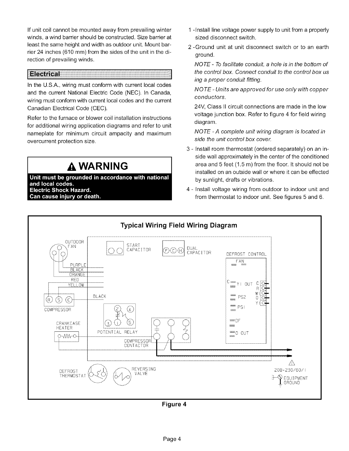
24V, Class It circuit connections are made in the low
voltage junction box, Refer to figure 4 for field wiring
diagram,
NQ TE -A complete unit wiring diagram is located in
side the unit control box cover.
3 - Install room thermostat (ordered separately) on an in-
side wall approximately in the center of the conditioned
area and 5 feet (1.5 m) from the floor, It should not be
installed on an outside wall or where it can be effected
by sunlight, drafts or vibrations,
4 - Install voltage wiring from outdoor to indoor unit and
from thermostat to indoor unit, See figures 5 and 6,
Typical Wiring Field Wiring Diagram
0U]OOOR
P( RPLE
BLACK
ORANGE
RED
COMPRESSOR
CRANKCASE
HEATER
BLACK
START
CAPACITOR DUAL
CAPACITOR DEFROST CONTROL
FAN
C YI OUT C_
RC>_._
W}
PS2 0 I0.
_ PSI
........OF
_0 OUT
DEFROS1
THERMOSTAT'
REVERSING
VALVE
A
208-250/60/}
EOUIPMENT
GROUND
7
Figure 4
Page 4
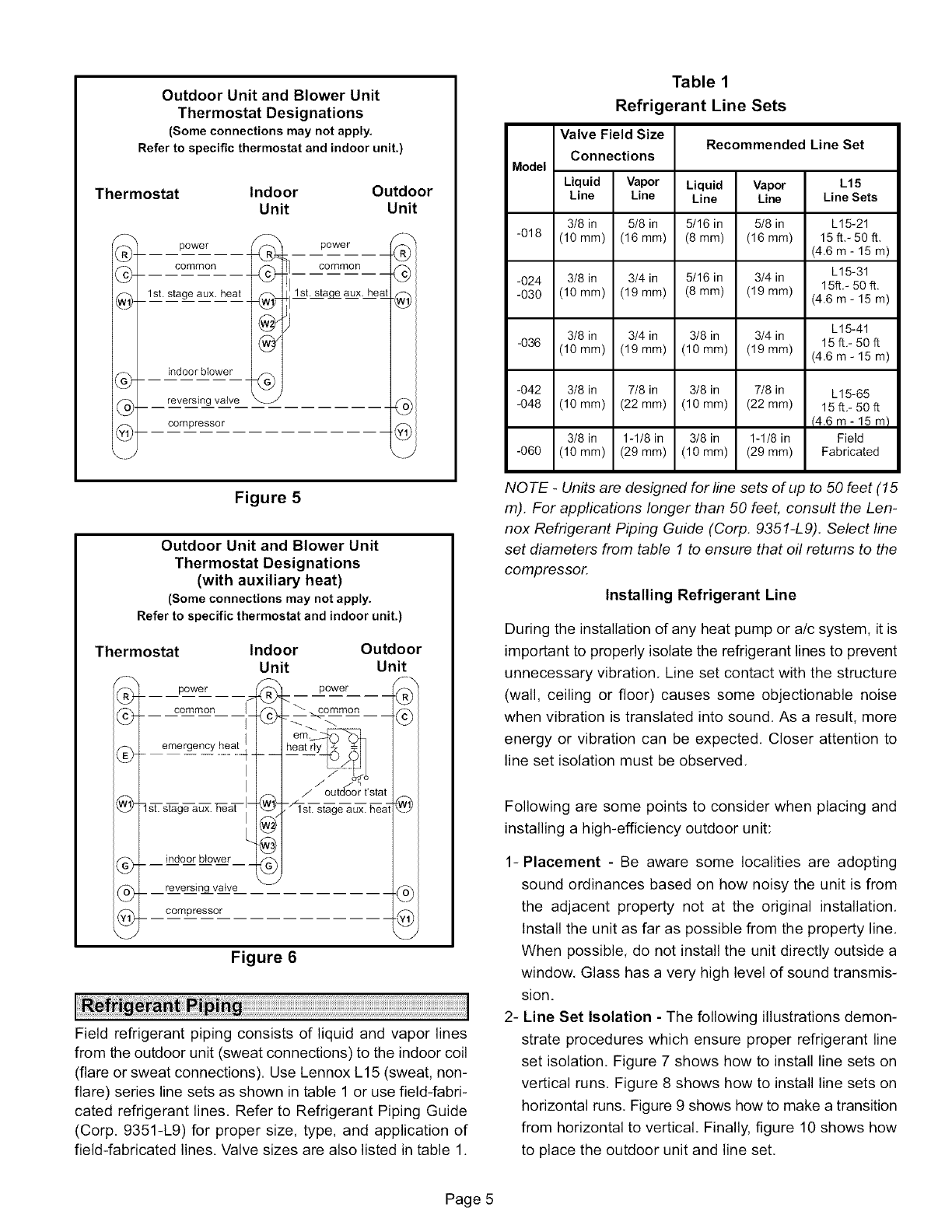
Outdoor Unit and Blower Unit
Thermostat Designations
(Some connections may not apply.
Refer to specific thermostat and indoor unit.)
Thermostat Indoor Outdoor
Unit Unit
F_
®4
cCcC
@÷
power
common
1st. stage aux. heat 4_
indoor blower
reversing valve _.J
power
common
1st. staqe aux. ileal
compressor
f_
-®1
@1
_J
Figure 5
Outdoor Unit and Blower Unit
Thermostat Designations
(with auxiliary heat)
(Some connections may not apply.
Refer to specific thermostat and indoor unit.)
Thermostat
(_ power I_
common
(_ _ emergency
I
I
1st. aux. TTeaq- -
stage
indoor blower
reversinq_vatve
compressor
Indoor Outdoor
Unit Unit
.®
:__ power_
he
'22 stat
"_-si%t_ _. _t
@1
®1
@1
@1
@l
Figure 6
Field refrigerant piping consists of liquid and vapor lines
from the outdoor unit (sweat connections) to the indoor coil
(flare or sweat connections). Use Lennox L15 (sweat, non-
flare) series line sets as shown in table 1 or use field-fabri-
cated refrigerant lines. Refer to Refrigerant Piping Guide
(Corp. 9351-L9) for proper size, type, and application of
field-fabricated lines. Valve sizes are also listed in table 1.
Table 1
Refrigerant Line Sets
Valve Field Size Recommended Line Set
Connections
Model
Liquid Vapor Liquid Vapor L15
Line Line Line Line Line Sets
3/8 in 5/8 in 5/16 in 5/8 in L15-21
-018 (10 mm) (16 mm) (8mm) (16 mm) 15 ft.- 50 ft.
(4.6 m- 15 m)
-024 3/8 in 3/4 in 5/16 in 3/4 in L15-31
15ft.- 50 ft.
-030 (10 mm) (19 mm) (8 ram) (19 ram) (4.6 m- 15 m)
L15-41
3/8 in 3/4 in 3/8 in 3/4 in 15ff.- 50ff
-036 (10 ram) (19 ram) (10 ram) (19 ram) (4.6 m- 15 m)
-042 3/8 in 7/8 in 3/8 in 7/8 in L15-65
-048 (10ram) (22ram) (10ram) (22ram) 15ft.-50ft
(4.6 m- 15 m)
3/8 in 1-1/8 in 3/8 in 1-1/8 in Field
-060 (10 mm) (29 mm) (10 mm) (29 mm) Fabricated
NOTE -Units are designed for line sets of up to 50 feet (15
m). For appfications longer than 50 feet consult the Len-
nox Refrigerant Piping Guide (Corp. 9351-L9). Select line
set diameters from table 1 to ensure that oil returns to the
compressor.
Installing Refrigerant Line
During the installation of any heat pump or a/c system, it is
important to properly isolate the refrigerant lines to prevent
unnecessary vibration. Line set contact with the structure
(wall, ceiling or floor) causes some objectionable noise
when vibration is translated into sound. As a result, more
energy or vibration can be expected. Closer attention to
line set isolation must be observed.
Following are some points to consider when placing and
installing a high-efficiency outdoor unit:
1-Placement -Be aware some localities are adopting
sound ordinances based on how noisy the unit is from
the adjacent property not at the original installation,
Install the unit as far as possible from the property line,
When possible, do not install the unit directly outside a
window, Glass has a very high level of sound transmis-
sion.
2- Line Set Isolation - The following illustrations demon-
strate procedures which ensure proper refrigerant line
set isolation. Figure 7 shows how to install line sets on
vertical runs. Figure 8 shows how to install line sets on
horizontal runs, Figure 9 shows how to make a transition
from horizontal to vertical, Finally, figure 10 shows how
to place the outdoor unit and line set,
Page 5
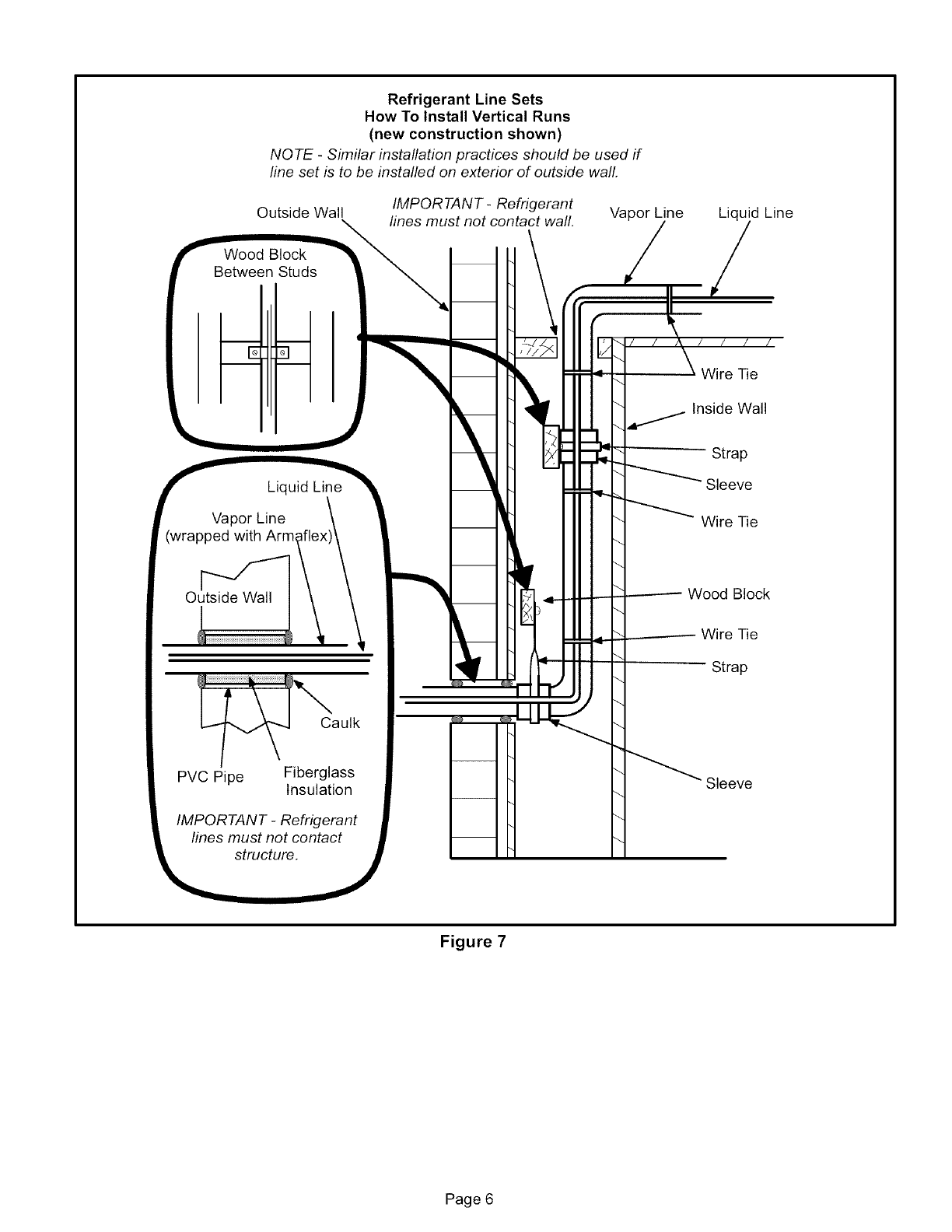
Refrigerant Line Sets
How To Install Vertical Runs
(new construction shown)
NOTE -Similar installation practices should be used if
fine set is to be installed on exterior of outside wall.
i
Outside Wall
\
Wood Block
r
Between Studs
f Liquid Lin_
Vapor Line
(wrapped with
Outside Wall
Caulk
PVC Pipe Fiberglass
Insulation
IMPORTANT -Refrigerant
lines must not contact i
structure, j
IMPORTANT- Refrigerant
lines must not contact wall.
m
m
L
Vapor Line Liquid Line
Wire Tie
"_ Inside Wall
'- Strap
_ Sleeve
\ Wire Tie
2------- Wood Block
_ Wire Tie
Strap
\_ Sleeve
Figure 7
Page 6
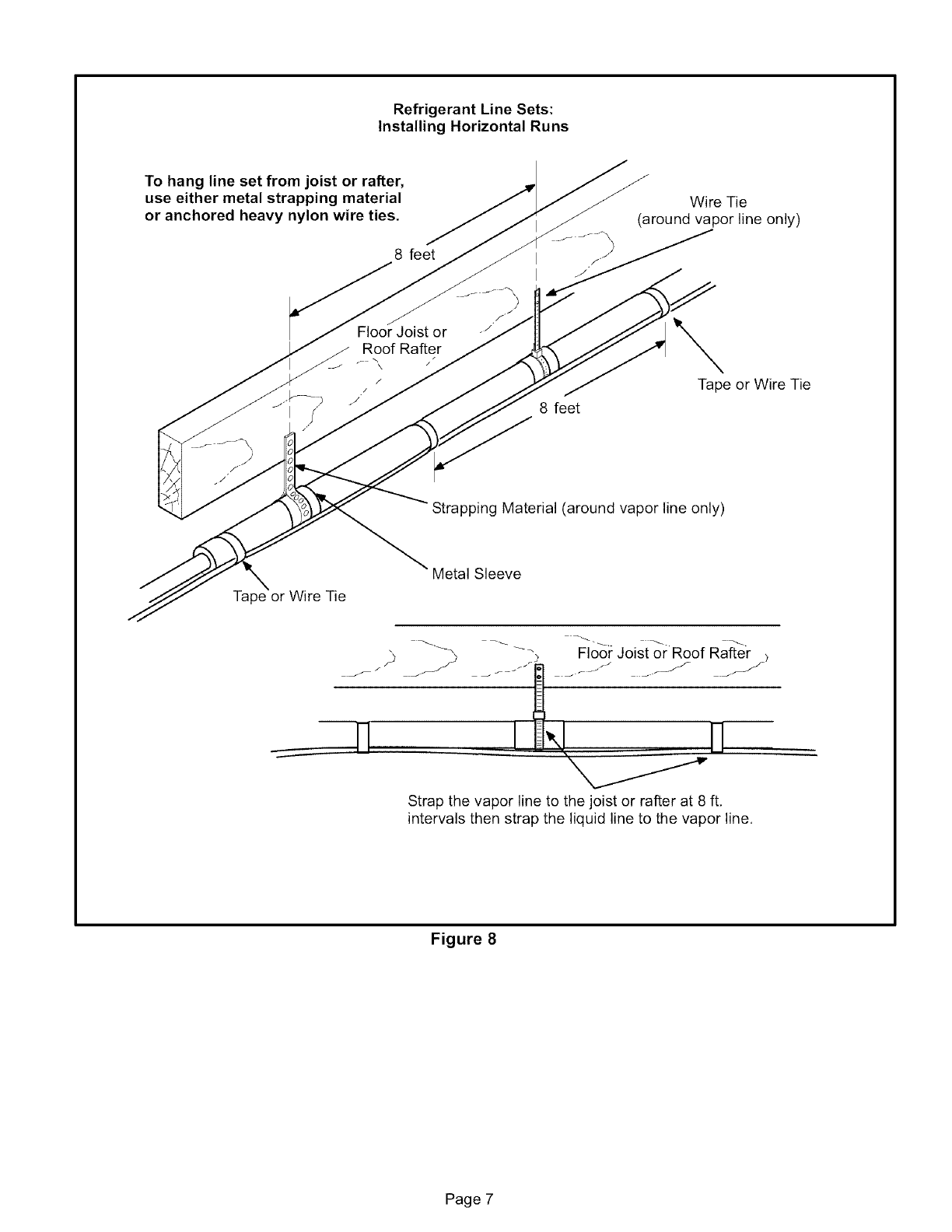
Refrigerant Line Sets:
Installing Horizontal Runs
To hang line set from joist or rafter,
use either metal strapping material
or anchored heavy nylon wire ties.
8 feet
Floor Joist or
Roof Rafter
p --,
/
/
I
I
Wire Tie
(around vapor line only)
.J
,f
8 feet
Tape or Wire Tie
Strapping Material (around vapor line only)
\
Tape or Wire Tie
Metal Sleeve
/
jr
_, Floor Joist or Roof Rafter )
Strap the vapor line to the joist or rafter at 8 ft.
intervals then strap the liquid line to the vapor line.
Figure 8
Page 7
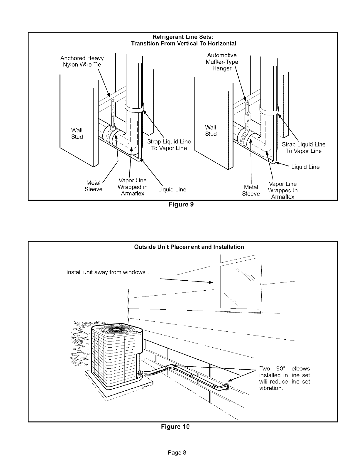
AnchoredHeavy
NylonWireTie
Refrigerant Line Sets:
Transition From Vertical To Horizontal
Automotive
Muffler-Type
Hanger
Wall
Stud
Metal
Strap Liquid Line
To Vapor Line
Wall
Stud
Sleeve
Vapor Line
Wrapped in
Armaflex
Strap Liquid Line
To Vapor Line
Liquid Line
Liquid Line
Figure 9
Metal
Sleeve
Vapor Line
Wrapped in
Armaflex
Outside Unit Placement and Installation
Install unit away from windows,
Figure 10
Page 8
Brazing Connection Procedure
1 - Cut ends of the refrigerant lines square (free from nicks
or dents), Debur the ends, The pipe must remain
round, do not pinch end of the line,
2 - Before making line set connections, use dry nitrogen to
purge the refrigerant piping. This will help to prevent
oxidation and the introduction of moisture into the sys-
tem,
3 - Use silver alloy brazing rods (5 or 6 percent minimum
silver alloy for copper-to-copper brazing or 45 percent
silver alloy for copper-to-brass or copper-to-steel braz-
ing) which are rated for use with HCFC22 refrigerant,
Wrap a wet cloth around the valve body and the copper
tube stub, Braze the line set to the service valve,
4 - Wrap a wet cloth around the valve body and copper
tube stub to protect it from heat damage during braz-
ing, Wrap another wet cloth underneath the valve body
to protect the base paint,
NQ TE -The tube end must stay bottomed in the fitting
during final assembly to ensure proper seating, sealing
and rigidity.
5- Install a field-provided thermal expansion valve (ap-
proved for use with HCFC22 refrigerant) in the liquid
line at the indoor coil,
Engineering Handbook for applicable expansion valves
for use with specific match-ups,
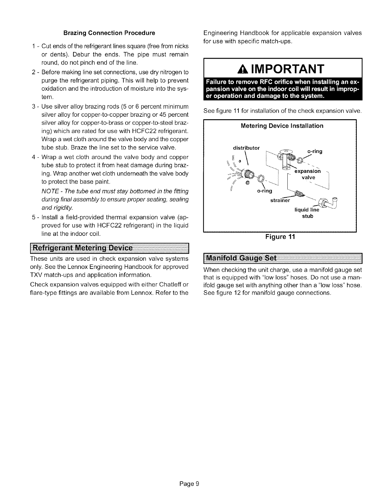
IMPORTANT
See figure 11 for installation of the check expansion valve.
Metering Device Installation
distributor
o\
o-ring
strainer
o-ring
expansmn
valve
liquid line
stub
Figure 11
These units are used in check expansion valve systems
only, See the Lennox Engineering Handbook for approved
TXV match-ups and application information,
Check expansion valves equipped with either Chatleff or
flare-type fittings are available from Lennox, Refer to the
When checking the unit charge, use a manifold gauge set
that is equipped with "low loss" hoses. Do not use a man-
ifold gauge set with anything other than a "low loss" hose,
See figure 12 for manifold gauge connections,
Page 9
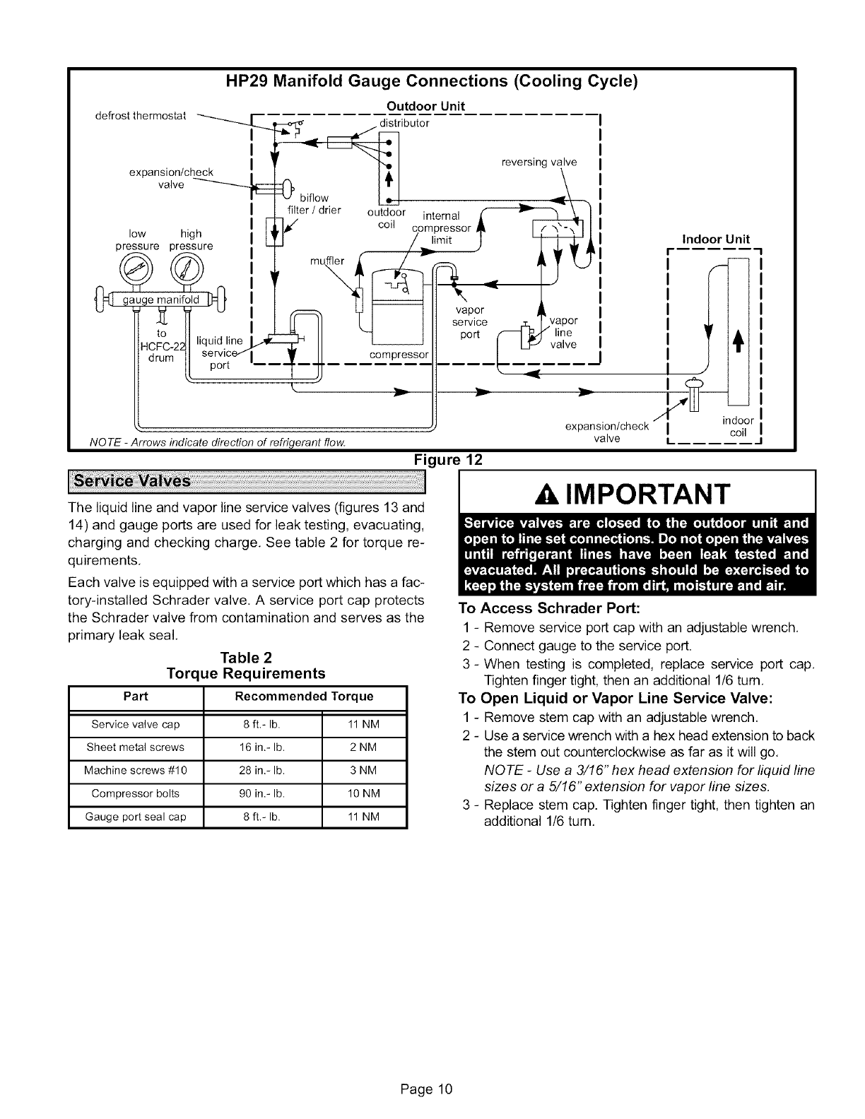
HP29 Manifold Gauge Connections (Cooling Cycle)
defrost thermostat "--_._
I
I
expansion/check
valve
low high
pressure pressure
0:[t ga ,ge_anifold I'J=0,
HCi2_-_2t/ 'iqsid'rl _
Outdoor Unit
_1 reversing valve
bif,ow h,_l ._\
outdoorinterna,r
filter/drier
_€/ coil compressor J_ E|[
/limit l _i
mu._ -r_L_ %-" j,_ _1
'fI %or 'vaor
I service
a_ II "-1 I port _ _ line
;" I1_ I _ valve
I--"_ compressor _ _
k
NO TE -Arrows indicate direction of refrigerant flow.
Indoor Unit
t
vY I
expansion/check I coil
valve LJ
Figure 12
The liquid line and vapor line service valves (figures 13 and
14) and gauge ports are used for leak testing, evacuating,
charging and checking charge. See table 2 for torque re-
quirements.
Each valve is equipped with a service port which has a fac-
tory-installed Schrader valve. A service port cap protects
the Schrader valve from contamination and serves as the
primary leak seal.
Table 2
Torque Requirements
Part Recommended Torque
Service valve cap 8 ft,- lb. 11 NM
Sheet metal screws 16 in.- lb. 2 NM
Machine screws #10 28 in.- lb. 3 NM
Compressor bolts 90 in.- lb. 10 NM
Gauge port seal cap 8 ft,- lb. 11 NM
AIMPORTANT
To Access Schrader Port:
1 - Remove service port cap with an adjustable wrench,
2 - Connect gauge to the service port.
3 - When testing is completed, replace service port cap,
Tighten finger tight, then an additional 1/6 turn,
To Open Liquid or Vapor Line Service Valve:
1 - Remove stem cap with an adjustable wrench,
2 - Use a service wrench with a hex head extension to back
the stem out counterclockwise as far as it will go,
NOTE -Use a 3/16" hex head extension for liquid line
sizes or a 5/16" extension for vapor line sizes.
3 - Replace stem cap. Tighten finger tight, then tighten an
additional 1/6 turn,
Page 10
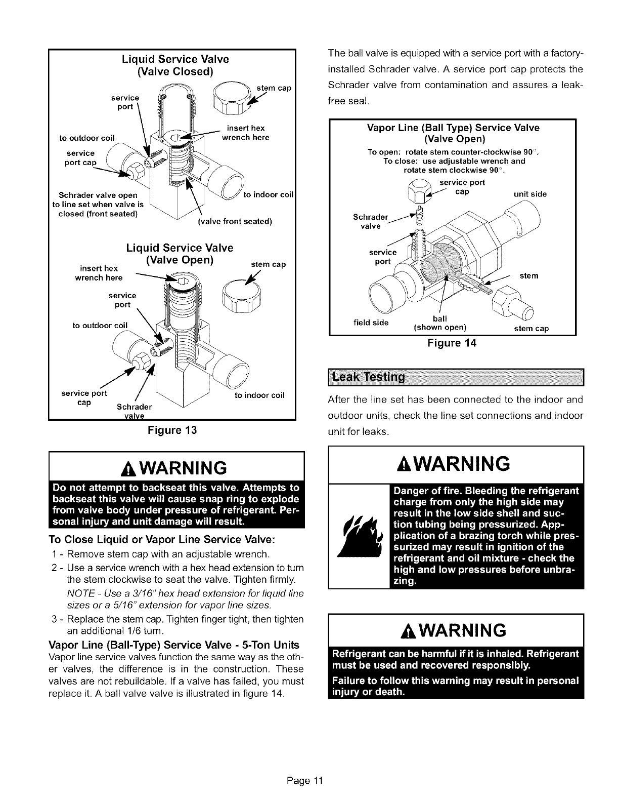
Liquid Service Valve
(Valve Closed) m
SepV_te
to outdoor coil insert hex
wrench here
service
port cap
Schrader valve open
to line set when valve is
closed (front seated)
cap
Lo indoor coil
(valve front seated)
insert hex
wrench here
Liquid Service Valve
service
port \
to outdoor coil
stem cap
(Valve Open)
service port to indoor coil
cap Schrader
valve
Figure 13
The ball valve is equipped with a service port with a factory-
installed Schrader valve. A service port cap protects the
Schrader valve from contamination and assures a leak-
free seal.
Vapor Line (Ball Type) Service Valve
(Valve Open)
To open: rotate stem counter-clockwise 90%
To close: use adjustable wrench and
rotate stem clockwise 90%
ervice port
cap unit side
SCharlavder/_
service
port
ste m
field side ball
(shown open)
Figure 14
stem cap
After the line set has been connected to the indoor and
outdoor units, check the line set connections and indoor
unit for leaks,
,WARNING
To Close Liquid or Vapor Line Service Valve:
1 - Remove stem cap with an adjustable wrench.
2 - Use a service wrench with a hex head extension to turn
the stem clockwise to seat the valve. Tighten firmly.
NOTE -Use a 3/16" hex head extension for liquid line
sizes or a 5/16" extension for vapor line sizes.
3 - Replace the stem cap. Tighten finger tight, then tighten
an additional 1/6 turn.
Vapor Line (Bali-Type) Service Valve -5-Ton Units
Vapor line service valves function the same way as the oth-
er valves, the difference is in the construction. These
valves are not rebuildable. If a valve has failed, you must
replace it. A ball valve valve is illustrated in figure 14.
-&WARNING
AWARNING
Page 11
-&WARNING IMPORTANT
,WARNING
Using an Electronic Leak Detector or Halide
1 - Connect a cylinder of HCFC-22 to the center port of the
manifold gauge set.
2 - With both manifold valves closed, open the valve on
the HCFC-22 cylinder (vapor only).
3 - Open the high pressure side of the manifold to allow
the HCFC-22 into the line set and indoor unit, Weigh in
a trace amount of HCFC-22, [A trace amount is a maxi-
mum of 2 ounces (57 g) or 3 pounds (31 kPa) pres-
sure,] Close the valve on the HCFC-22 cylinder and the
valve on the high pressure side of the manifold gauge
set. Disconnect the HCFC-22 cylinder,
4 - Connect a cylinder of nitrogen with a pressure regulat-
ing valve to the center port of the manifold gauge set,
5 - Connect the manifold gauge set high pressure hose to
the vapor valve service port. (Normally, the high pres-
sure hose is connected to the liquid line port; however,
connecting it to the vapor port better protects the man-
ifold gauge set from high pressure damage.)
6 - Adjust the nitrogen pressure to 150 psig (1034 kPa),
Open the valve on the high side of the manifold gauge
set which will pressurize line set and indoor unit,
7 - After a few minutes, open a refrigerant port to ensure
the refrigerant you added is adequate to be detected.
(Amounts of refrigerant will vary with line lengths.)
Check all joints for leaks, Purge nitrogen and HCFC-22
mixture, Correct any leaks and recheck,
Evacuating the system of noncondensables is critical for
proper operation of the unit. Noncondensables are defined
as any gas that will not condense under temperatures and
pressures present during operation of an air conditioning
system. Noncondensables and water vapor combine with
refrigerant to produce substances that corrode copper pip-
ing and compressor parts.
1 - Connect the manifold gauge set to the service valve
ports as follows:
• low pressure gauge to vapor line service valve
• high pressure gauge to liquid line service valve
2 - Connect micron gauge.
3 - Connect the vacuum pump (with vacuum gauge) to the
center port of the manifold gauge set,
4-Open both manifold valves and start the vacuum
pump.
5 - Evacuate the line set and indoor unit to an absolute
pressure of 23,000 microns (29,01 inches of mercu-
ry). During the early stages of evacuation, it is desir-
able to close the manifold gauge valve at least once to
determine if there is a rapid rise in absolute pressure.
A rapid rise in pressure indicates a relatively large leak,
If this occurs, repeat the leak testing procedure.
NOTE -The term absolute pressure means the total
actual pressure within a given volume or system,
above the absolute zero of pressure. Absolute pres-
sure in a vacuum is equal to atmospheric pressure mi-
nus vacuum pressure.
6 - When the absolute pressure reaches 23,000 microns
(29.01 inches of mercury), close the manifold gauge
valves, turn off the vacuum pump and disconnect the
manifold gauge center port hose from vacuum pump.
Attach the manifold center port hose to a nitrogen cylin-
der with pressure regulator set to 150 psig (1034 kPa)
and purge the hose. Open the manifold gauge valves
to break the vacuum in the line set and indoor unit.
Close the manifold gauge valves.
A CAUTION
_
_
Shut off the nitrogen cylinder and remove the manifold
gauge hose from the cylinder. Open the manifold
gauge valves to release the nitrogen from the line set
and indoor unit.
Reconnect the manifold gauge to the vacuum pump,
turn the pump on, and continue to evacuate the line set
and indoor unit until the absolute pressure does not
rise above 500 microns (29.9 inches of mercury) within
a 20-minute period after shutting off the vacuum pump
and closing the manifold gauge valves.
Page 12
9- Whentheabsolutepressurerequirementabovehas
beenmet,disconnectthemanifoldhosefromthevacu-
um pumpand connectit to an uprightcylinderof
HCFC-22refrigerant.Openthemanifoldgaugevalves
tobreakthevacuumfrom1to2psigpositivepressurein
the lineset and indoorunit,Closemanifoldgauge
valvesandshutofftheHCFC-22cylinderandremove
themanifoldgaugeset,
IMPORTANT
Cooling Start-Up
1 - Rotate fan to check for frozen bearings or binding.
2 - Inspect all factory- and field-installed wiring for loose
connections.
3 - After evacuation is complete, open the liquid line and
vapor line service valves (counterclockwise) to release
refrigerant charge (contained in outdoor unit) into the
system,
4 - Replace stem caps and secure finger tight, then tight-
en an additional (1/6) one-sixth of a turn,
5 - Check voltage supply at the disconnect switch. The
voltage must be within the range listed on the unit
nameplate. If not, do not start the equipment until the
power company has been consulted and the voltage
condition has been corrected.
6 - Set the thermostat for a cooling demand, turn on power
to indoor blower unit and close the outdoor unit discon-
nect to start the unit.
7 - Recheck voltage while the unit is running. Power must
be within range shown on the nameplate,
Three-Phase Compressor Rotation
Three-phase scroll compressors must be phased sequen-
tially to ensure correct compressor rotation and operation.
At compressor start-up, a rise in discharge and drop in va-
por pressures indicates proper compressor phasing and
operation, If discharge and vapor pressures do not perform
normally, follow the steps below to correctly phase the unit,
1 - Disconnect power to the unit,
2 - Reverse any two field power leads to the unit,
3 - Reapply power to the unit.
Discharge and vapor pressures should operate within their
normal start-up ranges,
NOTE - Compressor noise level may be significantly higher
when phasing is incorrect and the unit will not provide cool-
ing when compressor is operating backwards. Continued
backward operation will cause the compressor to cycle on
internal protector.
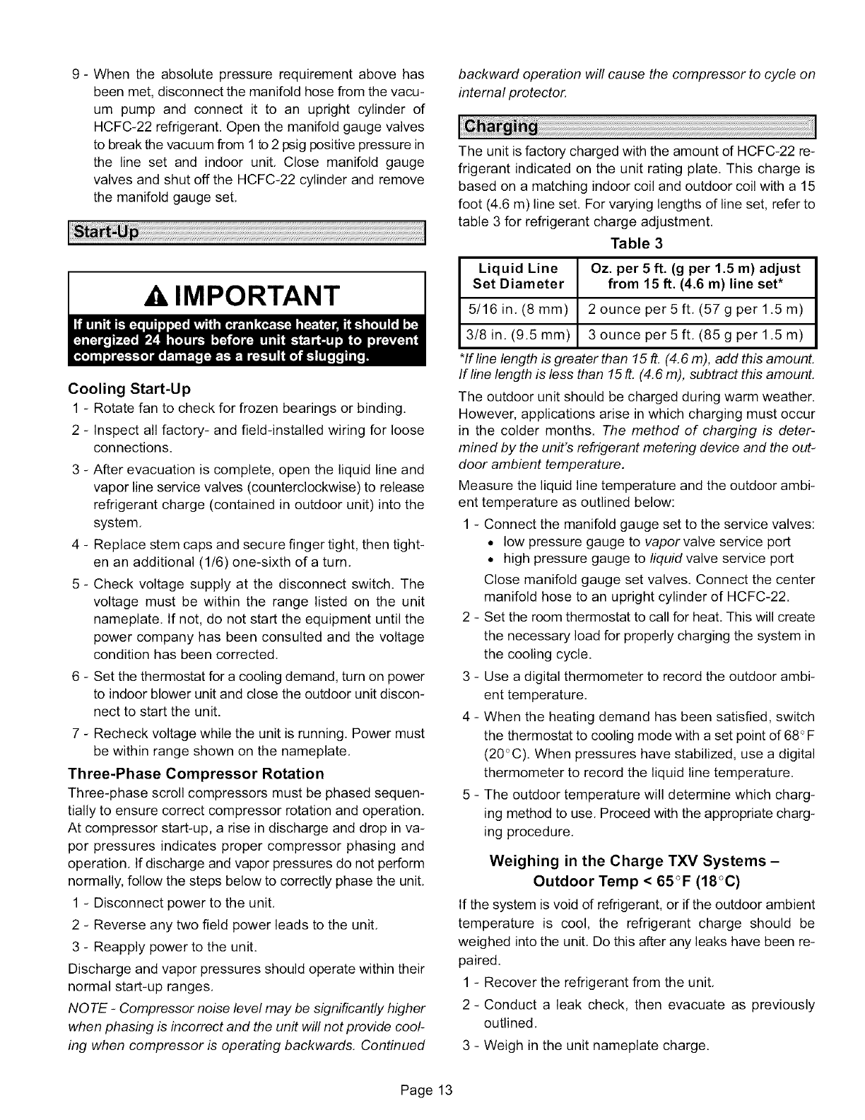
The unit is factory charged with the amount of HCFC-22 re-
frigerant indicated on the unit rating plate, This charge is
based on a matching indoor coil and outdoor coil with a 15
foot (4,6 m) line set. For varying lengths of line set, refer to
table 3 for refrigerant charge adjustment,
Table 3
Liquid Line Oz. per 5 ft. (g per 1.5 m) adjust
Set Diameter from 15 ft. (4.6 m) line set*
5/16 in, (8 mm) 2 ounce per 5 ft, (57 g per 1,5 m)
3/8 in, (9,5mm) 3 ounce per S ft, (85 g per1,S m)
*If line length is greater than 15 ft. (4.6 m), add this amount.
If line length is less than 15 ft. (4.6 m), subtract this amount.
The outdoor unit should be charged during warm weather.
However, applications arise in which charging must occur
in the colder months. The method of charging is deter-
mined by the unit's refrigerant metering device and the out-
door ambient temperature.
Measure the liquid line temperature and the outdoor ambi-
ent temperature as outlined below:
1 - Connect the manifold gauge set to the service valves:
• low pressure gauge to vapor valve service port
• high pressure gauge to fiquid valve service port
Close manifold gauge set valves. Connect the center
manifold hose to an upright cylinder of HCFC-22.
2 - Set the room thermostat to call for heat. This will create
the necessary load for properly charging the system in
the cooling cycle.
3 - Use a digital thermometer to record the outdoor ambi-
ent temperature,
4 - When the heating demand has been satisfied, switch
the thermostat to cooling mode with a set point of 68 °F
(20_%). When pressures have stabilized, use a digital
thermometer to record the liquid line temperature.
5 - The outdoor temperature will determine which charg-
ing method to use, Proceed with the appropriate charg-
ing procedure,
Weighing in the Charge TXV Systems -
Outdoor Temp < 65°F (18°C)
If the system is void of refrigerant, or if the outdoor ambient
temperature is cool, the refrigerant charge should be
weighed into the unit, Do this after any leaks have been re-
paired.
1 - Recover the refrigerant from the unit,
2 - Conduct a leak check, then evacuate as previously
outlined,
3 - Weigh in the unit nameplate charge,
Page 13
Ifweighingfacilitiesarenotavailableorifyouarecharging
theunitduringwarmweather,followoneoftheotherproce-
duresoutlinedbelow.
Subcooling Method
Outdoor Temp. < 65°F (18°C)
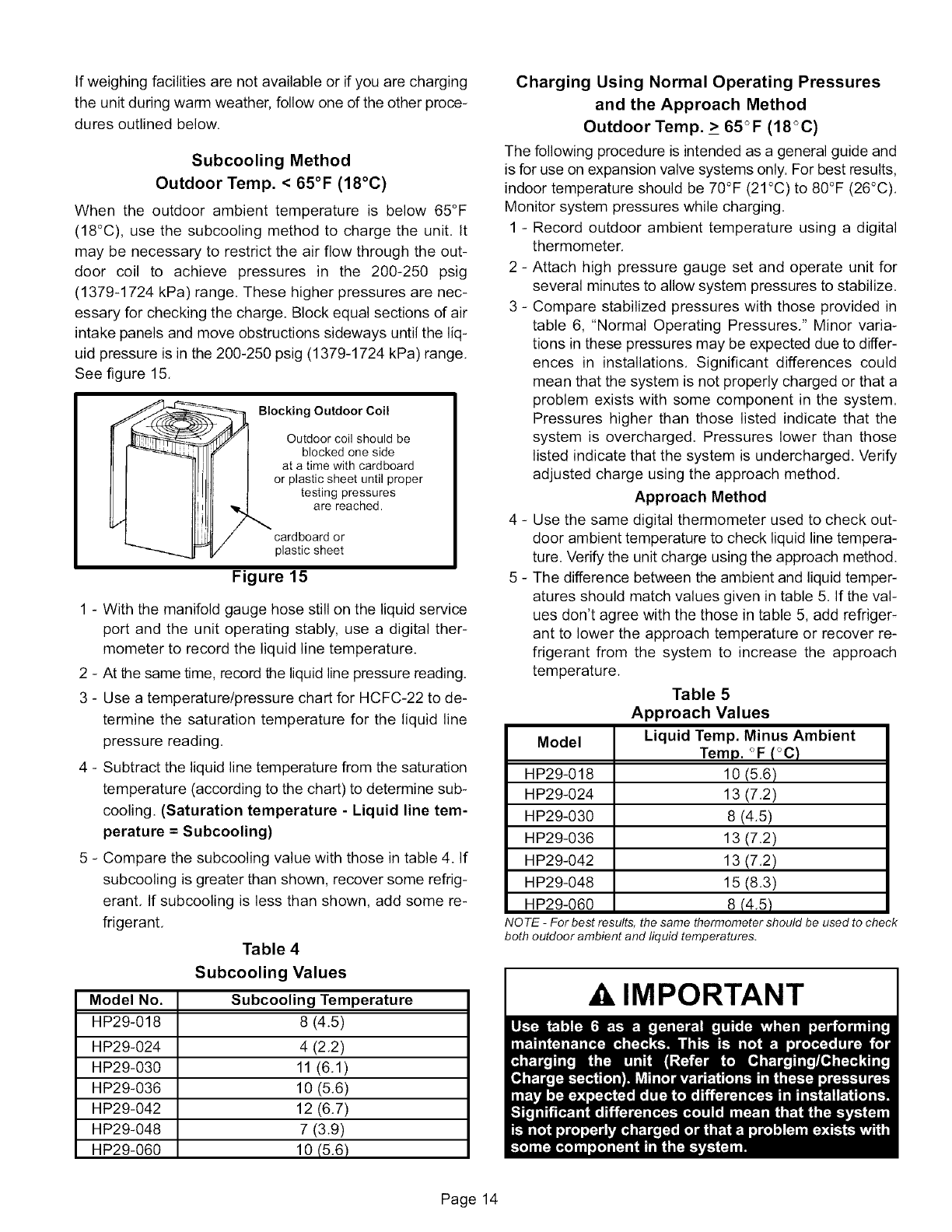
When the outdoor ambient temperature is below 65°F
(18°C), use the subcooling method to charge the unit, It
may be necessary to restrict the air flow through the out-
door coil to achieve pressures in the 200-250 psig
(1379-1724 kPa) range, These higher pressures are nec-
essary for checking the charge. Block equal sections of air
intake panels and move obstructions sideways until the liq-
uid pressure is in the 200-250 psig (1379-1724 kPa) range.
See figure 15.
Blocking Outdoor Coil
Outdoor coil should be
blocked one side
at a time with cardboard
or plastic sheet until proper
testing pressures
are reached.
cardboard or
plastic sheet
Figure 15
1 - With the manifold gauge hose still on the liquid service
port and the unit operating stably, use a digital ther-
mometer to record the liquid line temperature.
2 - At the same time, record the liquid line pressure reading,
3 - Use a temperature/pressure chart for HCFC-22 to de-
termine the saturation temperature for the liquid line
pressure reading.
4 - Subtract the liquid line temperature from the saturation
temperature (according to the chart) to determine sub-
cooling. (Saturation temperature - Liquid line tem-
perature = Subcooling)
5 - Compare the subcooling value with those in table 4. If
subcooling is greater than shown, recover some refrig-
erant, If subcooling is less than shown, add some re-
frigerant,
Table 4
Subcooling Values
Model No. Subcooling Temperature
HP29-018 8 (4.5)
HP29-024 4 (2.2)
HP29-030 11 (6.1)
HP29-036 10 (5.6)
HP29-042 12 (6.7)
HP29-048 7 (3.9)
HP29-060 10 (5.6)
Charging Using Normal Operating Pressures
and the Approach Method
Outdoor Temp. _>65°F (18°C)
The following procedure is intended as a general guide and
is for use on expansion valve systems only. For best results,
indoor temperature should be 70°F (21°C) to 80°F (26°C).
Monitor system pressures while charging.
1 - Record outdoor ambient temperature using a digital
thermometer,
2 - Attach high pressure gauge set and operate unit for
several minutes to allow system pressures to stabilize,
3 - Compare stabilized pressures with those provided in
table 6, "Normal Operating Pressures," Minor varia-
tions in these pressures may be expected due to differ-
ences in installations, Significant differences could
mean that the system is not properly charged or that a
problem exists with some component in the system.
Pressures higher than those listed indicate that the
system is overcharged. Pressures lower than those
listed indicate that the system is undercharged. Verify
adjusted charge using the approach method.
Approach Method
4 - Use the same digital thermometer used to check out-
door ambient temperature to check liquid line tempera-
ture. Verify the unit charge using the approach method.
5 - The difference between the ambient and liquid temper-
atures should match values given in table 5. If the val-
ues don't agree with the those in table 5, add refriger-
ant to lower the approach temperature or recover re-
frigerant from the system to increase the approach
temperature.
Table 5
Approach Values
Model Liquid Temp. Minus Ambient
Temp. _F (_C)
HP29-018 10 (5,6)
HP29-024 13 (7,2)
HP29-030 8 (4.5)
HP29-036 13 (7.2)
HP29-042 13 (7.2)
HP29-048 15 (8.3)
HP29-060 8 (4.5)
NOTE -For best results, the same thermometer should be used to check
both outdoor ambient and liquid temperatures.
AIMPORTANT
Page 14
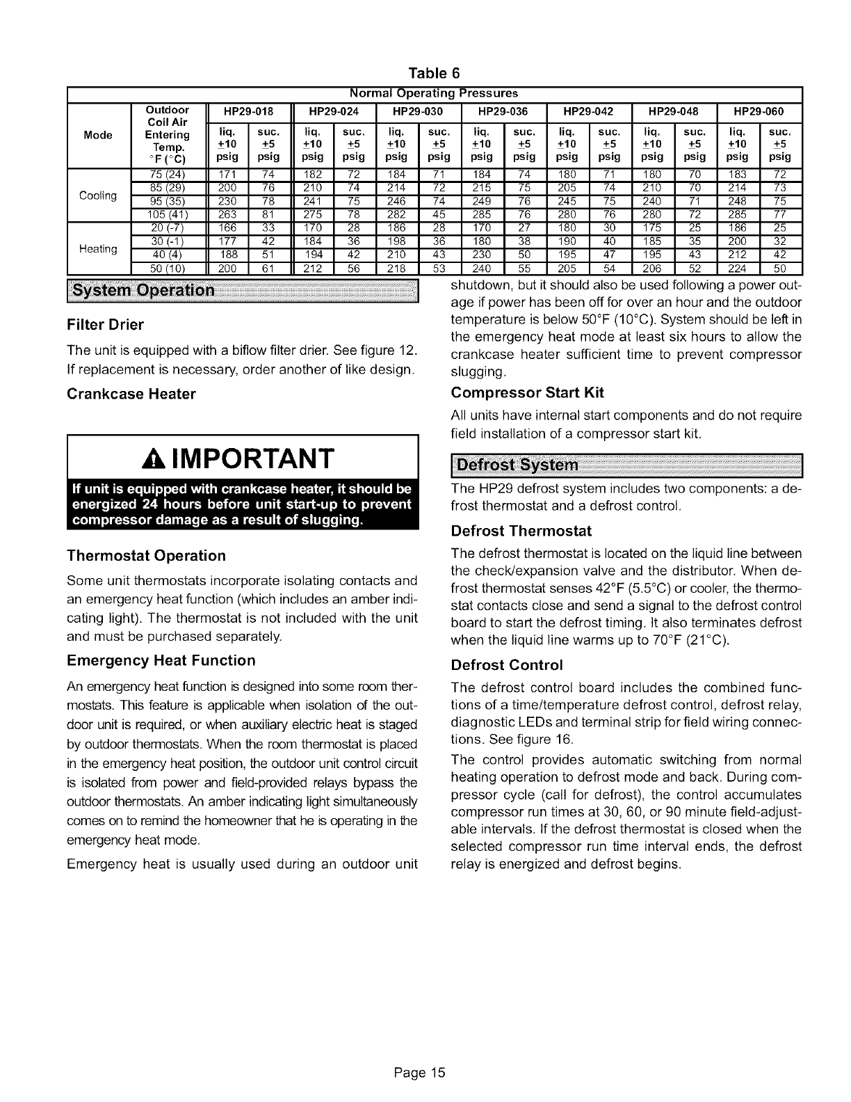
Table 6
Normal Operating Pressures
Outdoor HP29-018 HP29-024 HP29-030 HP29-036 HP29-042 HP29-048 HP29_060
Coil Air
Mode Entering liq. suc. liq. suc. liq. suc. liq. suc. liq. suc. liq. suc. liq. suc.
Temp. +10 +5 +10 +5 +10 +5 +10 +5 +10 +5 +10 +5 +10 +5
"F (°C) psig psig psig psig psig psig psig psig psig psig psig psig psig psig
75 (24) 171 74 182 72 184 71 184 74 180 71 180 70 183 72
85 (29) 200 76 210 74 214 72 215 75 205 74 210 70 214 73
Cooling 95 (35) 230 78 241 75 246 74 249 76 245 75 240 71 248 75
105 (41) 263 81 275 78 282 45 285 76 280 76 280 72 285 77
20 (-7) 166 33 170 28 186 28 170 27 180 30 175 25 186 25
30 (-1) 177 42 184 36 198 36 180 38 190 40 185 35 200 32
Heating 40 (4) 188 51 194 42 210 43 230 50 195 47 195 43 212 42
50 (10) 200 61 212 56 218 53 240 55 205 54 206 52 224 50
Filter Drier
The unit is equipped with a bifiow filter drier. See figure 12.
If replacement is necessary, order another of like design.
Crankcase Heater
IMPORTANT
shutdown, but it should also be used following a power out-
age if power h_ h_ e,_ ....... an h...... ,4 _h.... _,4_,
temperature is below 50°F (10°C). System should be left in
the emergency heat mode at least six hours to allow the
crankcase heater sufficient time to prevent compressor
slugging.
Compressor Start Kit
All units have internal start components and do not require
field installation of a compressor start kit.
The HP29 defrost system includes two components: a de-
frost thermostat and a defrost control.
Thermostat Operation
Some unit thermostats incorporate isolating contacts and
an emergency heat function (which includes an amber indi-
cating light). The thermostat is not included with the unit
and must be purchased separately.
Emergency Heat Function
An emergency heat function is designed into some room ther-
mostats. This feature is applicable when isolation of the out-
door unit is required, or when auxiliary electric heat is staged
by outdoor thermostats. When the room thermostat is placed
in the emergency heat position, the outdoor unit control circuit
is isolated from power and field-provided relays bypass the
outdoor thermostats. An amber indicating light simultaneously
comes on to remind the homeowner that he is operating in the
emergency heat mode.
Emergency heat is usually used during an outdoor unit
Defrost Thermostat
The defrost thermostat is located on the liquid line between
the check/expansion valve and the distributor. When de-
frost thermostat senses 42°F (5.5°C) or cooler, the thermo-
stat contacts close and send a signal to the defrost control
board to start the defrost timing. It also terminates defrost
when the liquid line warms up to 70°F (21°C).
Defrost Control
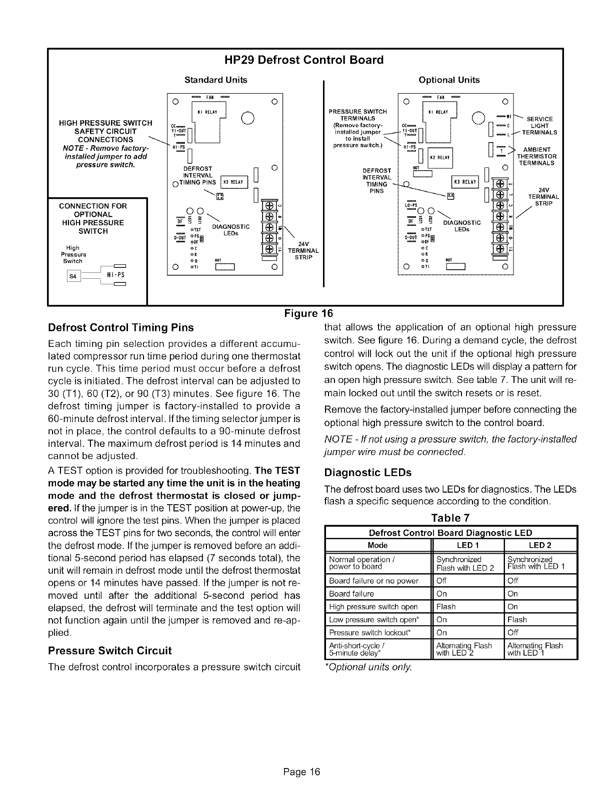
The defrost control board includes the combined func-
tions of a time/temperature defrost control, defrost relay,
diagnostic LEDs and terminal strip for field wiring connec-
tions. See figure 16.
The control provides automatic switching from normal
heating operation to defrost mode and back. During com-
pressor cycle (call for defrost), the control accumulates
compressor run times at 30, 60, or 90 minute field-adjust-
able intervals. If the defrost thermostat is closed when the
selected compressor run time interval ends, the defrost
relay is energized and defrost begins.
Page 15
HIGH PRESSURE SWITCH
SAFETY CIRCUIT
CONNECTIONS
NOTE -Remove factory-
installed jumper to add
pressure switch.
CONNECTION FOR
OPTIONAL
HIGH PRESSURE
SWITCH
High
Pressure
Switch
HP29 Defrost Control Board
Standard Units
FAN
0
,.P=js_
DEFROST
INTERVAL
oTIMING PINS
IDIAGNOSTIC
OTST LEDs
O_ op$
og
OR
o 0 _T
0 o,,
0
0
24V
TERMINAL
STRIP
O
PRESSURE SWITCH
TERMINALS
(Remove factory=
installed jumper
to install
pressure switch.)
DEFROST
INTERVAL
TIMING
PINS
Optional Units
i FAN °
HOT
%? °'At °ST'C
OR
0 oY, I'''''"3 0
SERVICE
LIGHT
tTERMINALS
•AMBIENT
THERMISTOR
TERMINALS
24V
TERMINAL
STRIP
/
Figure
Defrost Control Timing Pins
Each timing pin selection provides a different accumu-
lated compressor run time period during one thermostat
run cycle. This time period must occur before a defrost
cycle is initiated. The defrost interval can be adjusted to
30 (T1), 60 (T2), or 90 (T3) minutes, See figure 16, The
defrost timing jumper is factory-installed to provide a
60-minute defrost interval, Ifthe timing selector jumper is
not in place, the control defaults to a 90-minute defrost
interval, The maximum defrost period is 14 minutes and
cannot be adjusted,
A TEST option is provided for troubleshooting, The TEST
mode may be started any time the unit is in the heating
mode and the defrost thermostat is closed or jump-
ered. If the jumper is in the TEST position at power-up, the
control will ignore the test pins. When the jumper is placed
across the TEST pins for two seconds, the control will enter
the defrost mode. If the jumper is removed before an addi-
tional 5-second period has elapsed (7 seconds total), the
unit will remain in defrost mode until the defrost thermostat
opens or 14 minutes have passed. If the jumper is not re-
moved until after the additional 5-second period has
elapsed, the defrost will terminate and the test option will
not function again until the jumper is removed and re-ap-
plied.
Pressure Switch Circuit
The defrost control incorporates a pressure switch circuit
16
that allows the application of an optional high pressure
switch. See figure 16. During a demand cycle, the defrost
control will lock out the unit if the optional high pressure
switch opens. The diagnostic LEDs will display a pattern for
an open high pressure switch. See table 7. The unit will re-
main locked out until the switch resets or is reset.
Remove the factory-installed jumper before connecting the
optional high pressure switch to the control board.
NOTE -If not using a pressure switch, the factory-installed
jumper wire must be connected.
Diagnostic LEDs
The defrost board uses two LEDs for diagnostics. The LEDs
flash a specific sequence according to the condition.
Table 7
Defrost Control Board Diagnostic LED
Mode LED 1 LED 2
Normal operation /
power to board
Board failure or no power
Board failure
High pressure switch open
Low pressure switch open*
Pressure switch lockout*
Anti-short-cycle /
5-minute delay*
*Optional units only.
Synchronized Synchronized
Flash with LED 2 Frash with LED 1
Off Off
On On
Flash On
On Flash
On Off
Alternating Flash Alternating Flash
with LED 2 with LED 1
Page 16
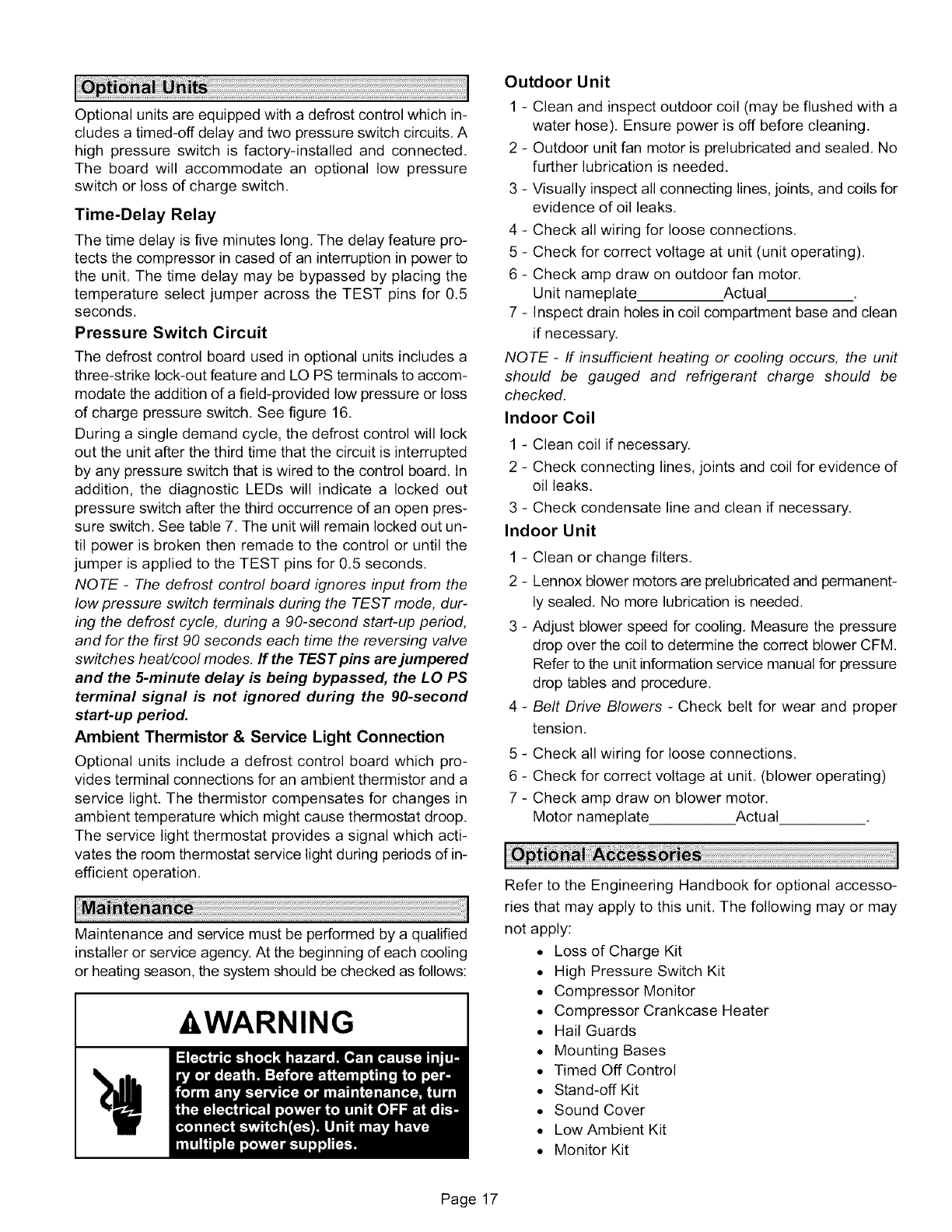
Optionalunitsareequippedwithadefrostcontrolwhichin-
cludesatimed-offdelayandtwopressureswitchcircuits.A
highpressureswitchisfactory-installedandconnected.
Theboardwill accommodatean optionallowpressure
switchorlossof chargeswitch.
Time-DelayRelay
The time delay is five minutes long. The delay feature pro-
tects the compressor in cased of an interruption in power to
the unit. The time delay may be bypassed by placing the
temperature select jumper across the TEST pins for 0,5
seconds.
Pressure Switch Circuit
The defrost control board used in optional units includes a
three-strike lock-out feature and LOPS terminals to accom-
modate the addition of a field-provided low pressure or loss
of charge pressure switch, See figure 16.
During a single demand cycle, the defrost control will lock
out the unit after the third time that the circuit is interrupted
by any pressure switch that is wired to the control board, In
addition, the diagnostic LEDs will indicate a locked out
pressure switch after the third occurrence of an open pres-
sure switch, See table 7. The unit will remain locked out un-
til power is broken then remade to the control or until the
jumper is applied to the TEST pins for 0.5 seconds.
NOTE -The defrost control board ignores input from the
low pressure switch terminals during the TEST mode, dur-
ing the defrost cycle, during a 90-second start-up period,
and for the first 90 seconds each time the reversing valve
switches heat/cool modes, If the TEST pins are jumpered
and the 5-minute delay is being bypassed, the LO PS
terminal signal is not ignored during the 90-second
start-up period.
Ambient Thermistor & Service Light Connection
Optional units include a defrost control board which pro-
vides terminal connections for an ambient thermistor and a
service light. The thermistor compensates for changes in
ambient temperature which might cause thermostat droop.
The service light thermostat provides a signal which acti-
vates the room thermostat service light during periods of in-
efficient operation,
Maintenance and service must be performed by a qualified
installer or service agency. At the beginning of each cooling
or heating season, the system should be checked as follows:
-&WARNING
Outdoor Unit
1 - Clean and inspect outdoor coil (may be flushed with a
water hose). Ensure power is off before cleaning.
2 - Outdoor unit fan motor is prelubricated and sealed, No
further lubrication is needed.
3 - Visually inspect all connecting lines, joints, and coils for
evidence of oil leaks,
4 - Check all wiring for loose connections,
5 - Check for correct voltage at unit (unit operating),
6 - Check amp draw on outdoor fan motor.
Unit nameplate Actual
7 - Inspect drain holes in coil compartment base and clean
if necessary.
NQ TE -If insufficient heating or cooling occurs, the unit
should be gauged and refrigerant charge should be
checked,
Indoor Coil
1 - Clean coil if necessary.
2 - Check connecting lines, joints and coil for evidence of
oil leaks,
3 - Check condensate line and clean if necessary,
Indoor Unit
1 - Clean or change filters,
2 - Lennox blower motors are prelubricated and permanent-
ly sealed, No more lubrication is needed.
3 - Adjust blower speed for cooling, Measure the pressure
drop over the coil to determine the correct blower CFM
Refer to the unit information service manual for pressure
drop tables and procedure.
4 - Belt Drive Blowers - Check belt for wear and proper
tension,
5 - Check all wiring for loose connections,
6 - Check for correct voltage at unit, (blower operating)
7 - Check amp draw on blower motor.
Motor nameplate Actual
Refer to the Engineering Handbook for optional accesso-
ries that may apply to this unit, The following may or may
not apply:
• Loss of Charge Kit
• High Pressure Switch Kit
• Compressor Monitor
• Compressor Crankcase Heater
• Hail Guards
• Mounting Bases
• Timed Off Control
• Stand-off Kit
• Sound Cover
• Low Ambient Kit
• Monitor Kit
Page 17
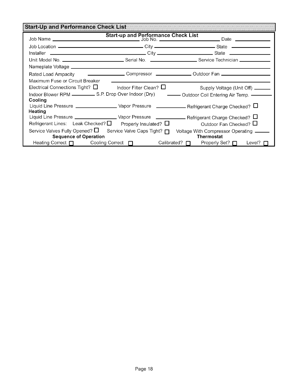
JobName Start-up and Performance Check List
Job No, Date
Job Location
Installer
Unit Model No,
City
City
Serial No,
State
State
Service Technician
Nameplate Voltage
Rated Load Ampacity
Maximum Fuse or Circuit Breaker
Electrical Connections Tight? []
Indoor Blower RPM
Cooling
Liquid Line Pressure
Heating
Liquid Line Pressure
Refrigerant Lines: Leak Checked? []
Service Valves Fully Opened? []
Sequence of Operation
Heating Correct []
Compressor
Indoor Filter Clean? []
S,R Drop Over Indoor (Dry)
Vapor Pressure
Outdoor Fan
Supply Voltage (Unit Off) __
-- Outdoor Coil Entering Air Temp.
Refrigerant Charge Checked? []
Vapor Pressure
Properly Insulated? []
Service Valve Caps Tight? []
Refrigerant Charge Checked? []
Outdoor Fan Checked? []
Cooling Correct []
Voltage With Compressor Operating --
Thermostat
Calibrated? [] Properly Set? [] Level? []
Page 18
