LENNOX Air Conditioner/heat Pump(outside Unit) Manual L0806493
User Manual: LENNOX LENNOX Air conditioner/heat pump(outside unit) Manual LENNOX Air conditioner/heat pump(outside unit) Owner's Manual, LENNOX Air conditioner/heat pump(outside unit) installation guides
Open the PDF directly: View PDF ![]() .
.
Page Count: 16
ZENNDX
,1_2000 Lennox industries Inc.
Dallas Texas, USA
HP40 heat pumps use R407C which is an ozone friendly
HFC refrigerant. This unit must be installed with a match-
ing indoor coil and line set as outlined in the Lennox Engi-
neering Handbook. HP40 heat pumps are designed for
use in expansion valve systems only. They are not de-
signed to be used in RFC systems. An expansion valve
and filter drier approved for use with R407C have been
shipped with the unit. These components must be
installed prior to unit operation.
,IMPORTANT
INSTALLATION
INSTRUCTIONS
HP40 Heat Pump Units
HEAT PUMP UNITS
1-1/2 through 5 ton
504,538M _-_ Technical
06/04 ''_LLZ2Publications
Supersedes 11/02 Litho U.S.A.
HP40 Heat Pump Unit .......................... 1
Shipping & Packing List ......................... 1
General Information ............................ 1
Unit Dimensions ............................... 2
Setting the Unit ................................ 3
Electrical ...................................... 4
Plumbing ...................................... 5
Refrigerant Metering Device ..................... 5
Manifold Gauge Set ............................ 7
Liquid & Vapor Line Service Valves ............... 7
Leak Testing ................................... 8
System Evacuation ............................. 9
Start-Up ....................................... 9
Charging Considerations ....................... 10
System Operation ............................. 12
Defrost System ............................... 12
Maintenance .................................. 13
RETAIN THESE INSTRUCTIONS
FOR FUTURE REFERENCE
1 - Assembled HP40 heat pump unit
1 - Bag assembly:
1 - Sight glass
1 - Coupling reducer, 5/16 x 3/8 inch (024)
Check unit for shipping damage. If any damage is found,
contact the last carrier immediately.
,WARNING These instructions are intended as a general guide and
do not supersede national or local codes in any way. Con-
sult authorities having jurisdiction before installation.
The HP40 unit is "CE marked" in accordance with the re-
quirements of the latest European Directives for Electrical
and Machinery Safety and Electromagnetic Compatibility.
In addition, HP40 units have type Approval Certification
with the Gas Appliance Directive.
A, WARNING IMPORTANT
06/04
IIIIIIllllllllllllBIIIIlfllIIIIIIIIlI Page 1 504,538M
IIIIIIIIIllllllllllIIIIIIIIIIIIIIIIIIIIIIIIlllllI
INLET
©
AIR
INLETS7 AIR HP40
iiii!,!ii!i!i;i!!i!ii iiii i iiiiii!!i OPT,ONAL
_T STAND-OFF KIT
(Field-installed
4 required)
AIR (Around perimeterof base)
_ LIQUID LINE
AIR CONNECTION
INLET'_
TOP VIEW
111
162
TOP VIEW BASE SECTION
111
111
e_. C=.=1
v
SIDE VIEW 19
A
ELECTRICAL
INLETS
51
OUTDOOR
COIL FAN
COMPRESSOR_
VAPOR &
LIQUID LINE
CONNECTION
7O
OPTIONAL
STAND-OFF KIT
(Field-installedJ
4required)
_-_ C
DISCNARGE_
_i!!i!!i!!i!iiiiiiii
SIDE VIEW
AIR
i_iiiiiiiiiiiiiiiiiiiiiiiiiiiiiiiiiiiiiiiiiiiiiiiiiiiiiiiiiiiiiiiiiiiiiiiiiiiiiiiiiii!!_
i!_i_ii!!!i'i_i!!i_,i!_i!!,i_!!_!i'i_i!i!!!i'i_i!i!!!i'i_i!_
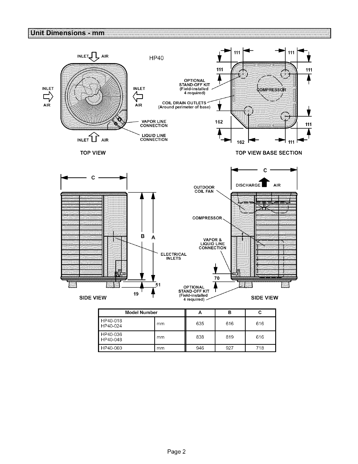
Model Number A B C
HP40-018
HP40-024 mm 635 616 616
HP40-036
HP40-048 mm 838 819 616
HP40-060 mm 946 927 718
Page 2
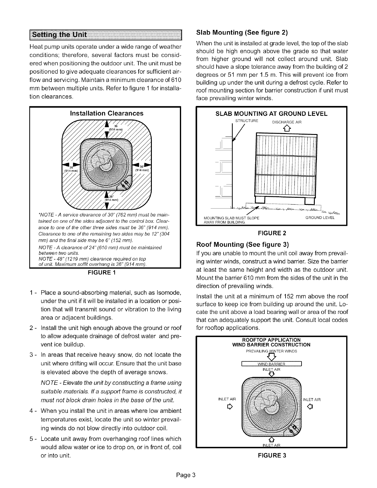
Heatpumpunitsoperateunderawiderangeofweather
conditions;therefore,severalfactorsmustbe consid-
eredwhenpositioningtheoutdoorunit,Theunitmustbe
positionedtogiveadequateclearancesforsufficientair-
flowandservicing,Maintainaminimumclearanced610
mm between multiple units. Refer to figure 1 for installa-
tion clearances.
Installation Clearances
/
/
/
/
*NOTE -Aservice clearance of 30" (762 ram) must be main-
rained on one of the sides adjacent to the control box. Clear-
anee to one of the other three sides must be 36" (914 ram).
Clearance toone of the remainingtwosides may be 12"(304
ram)and the finalside may be 6"(152 ram).
NO TE -Aclearance of 24" (6! 0 mm) must be maintained
between two units.
NOTE -48" (!2!9 mm) clearance required on top
of unit. Maximum soffit overhang is 36" (914 mm).
FIGURE 1
1 - Place a sound-absorbing material, such as Isomode,
under the unit if it will be installed in a location or posi-
tion that will transmit sound or vibration to the living
area or adjacent buildings.
2 - Install the unit high enough above the ground or roof
to allow adequate drainage of defrost water and pre-
vent ice buildup.
3 - In areas that receive heavy snow, do not locate the
unit where drifting will occur. Ensure that the unit base
is elevated above the depth of average snows.
NOTE -Elevate the unit by constructing a frame using
suitable materials. If a support frame is constructed, it
must not block drain holes in the base of the unit.
4 - When you install the unit in areas where low ambient
temperatures exist, locate the unit so winter prevail-
ing winds do not blow directly into outdoor coil.
5 - Locate unit away from overhanging roof lines which
would allow water or ice to drop on, or in front of, coil
or into unit.
Slab Mounting (See figure 2)
When the unit is installed at grade level, the top of the slab
should be high enough above the grade so that water
from higher ground will not collect around unit. Slab
should have a slope tolerance away from the building d2
degrees or 51 mm per 1,5 m. This will prevent ice from
building up under the unit during a defrost cycle, Refer to
roof mounting section for barrier construction if unit must
face prevailing winter winds.
SLAB MOUNTING AT GROUND LEVEL
STRUCTURE DISCHARGE AIR
/0
i/I/i//I/l,I/i,
MOUNTING SLAB MUST SLOPE
AWAY FROM BUILDING.
GROUND LEVEL
FIGURE 2
Roof Mounting (See figure 3)
If you are unable to mount the unit coil away from prevail-
ing winter winds, construct a wind barrier. Size the barrier
at least the same height and width as the outdoor unit.
Mount the barrier 610 mm from the sides of the unit in the
direction of prevailing winds.
Install the unit at a minimum of 152 mm above the roof
surface to keep ice from building up around the unit. Lo-
cate the unit above a load bearing wall or area of the roof
that can adequately support the unit, Consult local codes
for rooftop applications,
ROOFTOP APPLICATION
WIND BARRIER CONSTRUCTION
PREVAILING WINTER WINDS
I WIND BARRIER I
INLET AIR
0
INLET AIR
0
INLET AIR
INLET AIR
0
FIGURE 3
Page 3
Wiringmustconformwithcurrentlocalcodes.Anapplica-
tiondiagramisincludedinthisinstructionandintheindoor
unitinstructions.
Refertotheunitratingplate,locatedonthecontrolboxcov-
er,forminimumcircuitampacityandmaximumfusesize.
1- Providelinevoltagepowersupplyto theunitfroma
properlysizeddisconnectswitch.Thedisconnect
switchshouldbelocatedsothatitiseasilyaccessible
andwithinsightoftheunit.
2- Routethepowerandgroundwiresfromthediscon-
nectswitchtotheunit.Theelectricalopeningsare
providedunderthecontrolboxcover.Seetheunitdi-
mensionsillustrationonpage2,
3- Removethecontrolboxcoverandconnectthepower
wiringtothecontactor.Connectgroundwiretoground
lug.
4- Installtheroomthermostat(orderedseparately)in
theconditionedarea,Placethethermostatwhereit
willnotbeaffectedbysunlight,drafts,orvibration.Do
notinstallthethermostatonanoutsidewall.Themost
desirablepositionforthethermostatisnearthecen-
terof theconditionedareaandapproximately1,5m
fromthefloor,
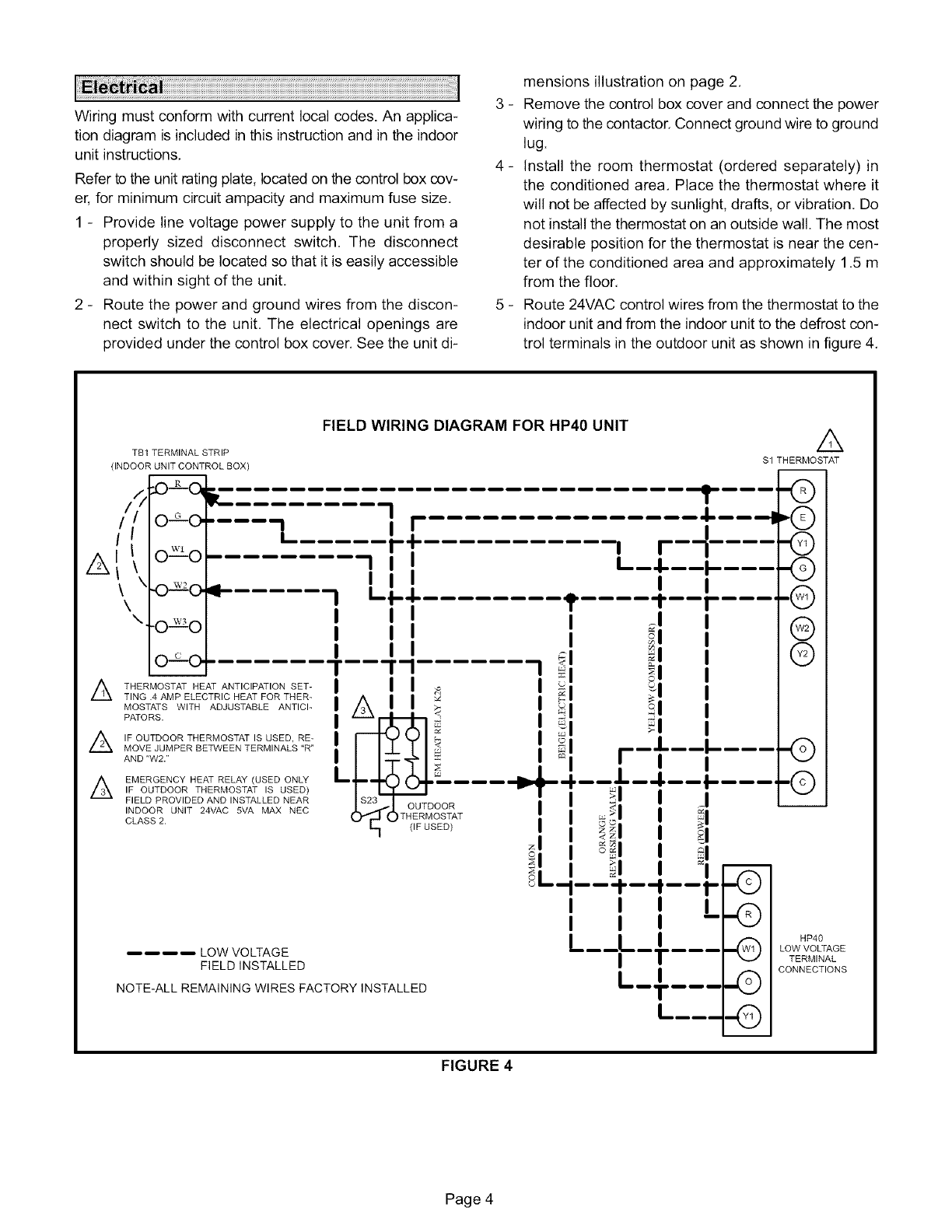
5- Route24VACcontrolwiresfromthethermostattothe
indoorunitandfromtheindoorunittothedefrostcon-
trolterminalsintheoutdoorunitasshowninfigure4,
//
A\\
A
TB1 TERMINAL STRIP
(INDOOR UNIT CONTROL BOX)
-.o_o_ __........ -I I'
OGO • ,, ::
-I I . L--.I-----.
.'20, L'L............ "......
"O '_'_O
O_.-_-O.
THERMOSTAT HEAT ANTICIPATION SET-
TING .4 AMP ELECTRIC HEAT FOR THER-
MOSTATS WITH ADJUSTABLE ANTICI-
PATORS.
A IF OUTDOOR THERMOSTAT IS USED, RE-
MOVE JUMPER BETWEEN TERMINALS "R"
AND "W2."
AEMERGENCY HEAT RELAY (USED ONLY
IF OUTDOOR THERMOSTAT IS USED)
FIELD PROVIDED AND INSTALLED NEAR
INDOOR UNIT 24VAC 5VA MAX NEC
CLASS 2.
FIELD WIRING DIAGRAM FOR HP4O UNIT A
$1 THERMOSTAT
=inn =,_
A
L_-----.-!,.,
OUTDOOR
THERMOSTAT
I _1
_1 _.1.
=1 .I- I
21
_L_
eRie
J
_l _1
<7_1
_l _l
_l t1
--I--'--,'- -Z
I --
___L_, ..@
t
L...... ..@
-@
LOW VOLTAGE
FIELD INSTALLED
NOTE-ALL REMAINING WIRES FACTORY INSTALLED
m
-©
.©
8
-®
@
©
HP40
LOW VOLTAGE
TERMINAL
CONNECTIONS
FIGURE 4
Page 4
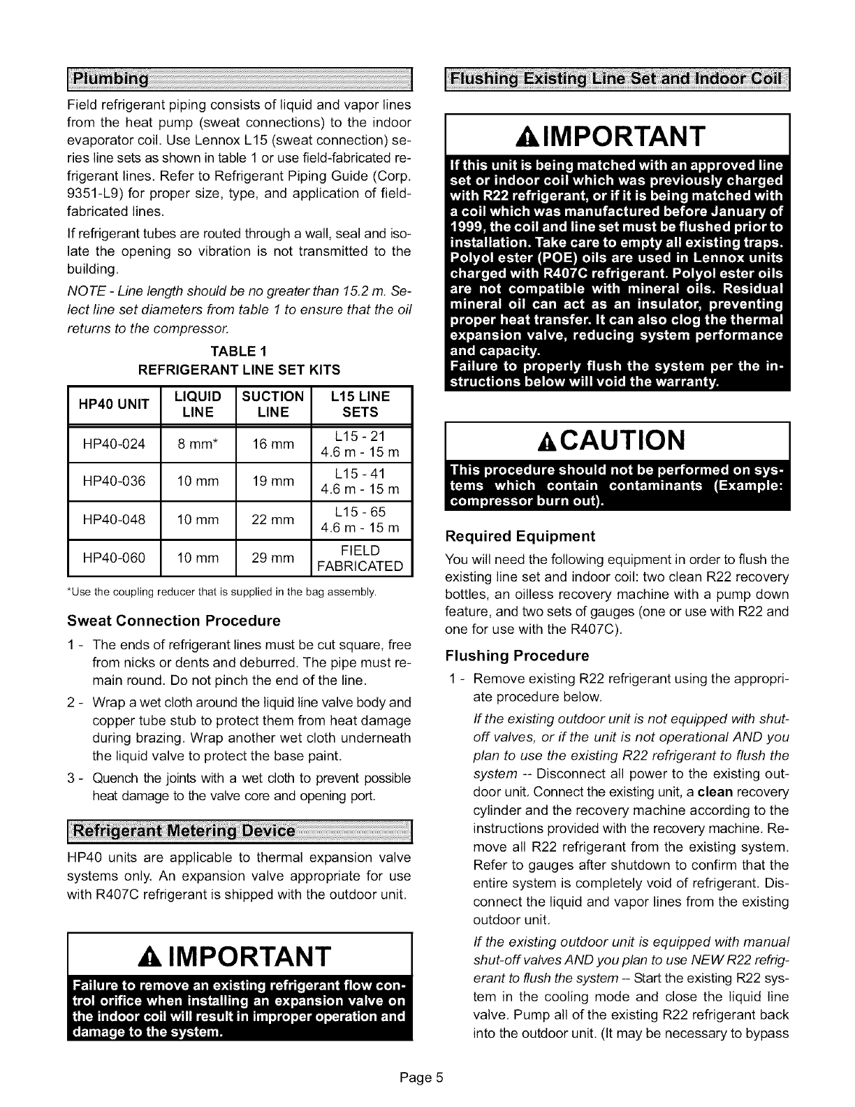
Fieldrefrigerantpipingconsistsofliquidandvaporlines
fromtheheatpump(sweatconnections)to theindoor
evaporatorcoil,UseLennoxL15(sweatconnection)se-
rieslinesetsasshownintable1orusefield-fabricatedre-
frigerantlines,Referto RefrigerantPipingGuide(Corp.
9351-L9)for propersize,type,andapplicationof field-
fabricatedlines.
Ifrefrigeranttubesareroutedthroughawall,sealandiso-
latetheopeningsovibrationis nottransmittedto the
building.
NOTE -Line length should be no greater than 15,2 m, Se-
lect line set diameters from table I to ensure that the oil
returns to the compressor.
TABLE 1
REFRIGERANT LINE SET KITS
HP40 UNIT LIQUID SUCTION L15 LINE
LINE LINE SETS
L15-21
HP40-024 8 mm* 16 mm 4.6m- 15m
L15 -41
HP40-036 10 mm 19 mm 4.6m- 15m
L15 - 65
HP40-048 10 mm 22 mm 4.6m- 15m
FIELD
HP40-060 10 mm 29 mm FABRICATED
*Use the coupling reducer that is supplied in the bag assembly.
Sweat Connection Procedure
1 - The ends of refrigerant lines must be cut square, free
from nicks or dents and deburred. The pipe must re-
main round, Do not pinch the end of the line.
2 - Wrap a wet cloth around the liquid line valve body and
copper tube stub to protect them from heat damage
during brazing, Wrap another wet cloth underneath
the liquid valve to protect the base paint,
3 - Quench the joints with a wet cloth to prevent possible
heat damage to the valve core and opening port,
HP40 units are applicable to thermal expansion valve
systems only. An expansion valve appropriate for use
with R407C refrigerant is shipped with the outdoor unit,
A IMPORTANT
AIMPORTANT
_&CAUTION
Required Equipment
You will need the following equipment in order to flush the
existing line set and indoor coil: two clean R22 recovery
bottles, an oilless recovery machine with a pump down
feature, and two sets of gauges (one or use with R22 and
one for use with the R407C).
Flushing Procedure
1 - Remove existing R22 refrigerant using the appropri-
ate procedure below.
If the existing outdoor unit is not equipped with shut-
off valves, or if the unit is not operational AND you
plan to use the existing R22 refrigerant to flush the
system -- Disconnect all power to the existing out-
door unit. Connect the existing unit, a clean recovery
cylinder and the recovery machine according to the
instructions provided with the recovery machine. Re-
move all R22 refrigerant from the existing system.
Refer to gauges after shutdown to confirm that the
entire system is completely void of refrigerant. Dis-
connect the liquid and vapor lines from the existing
outdoor unit.
If the existing outdoor unit is equipped with manual
shut-off valves AND you plan to use NEW R22 refrig-
erant to flush the system -- Start the existing R22 sys-
tem in the cooling mode and close the liquid line
valve. Pump all of the existing R22 refrigerant back
into the outdoor unit. (It may be necessary to bypass
Page 5
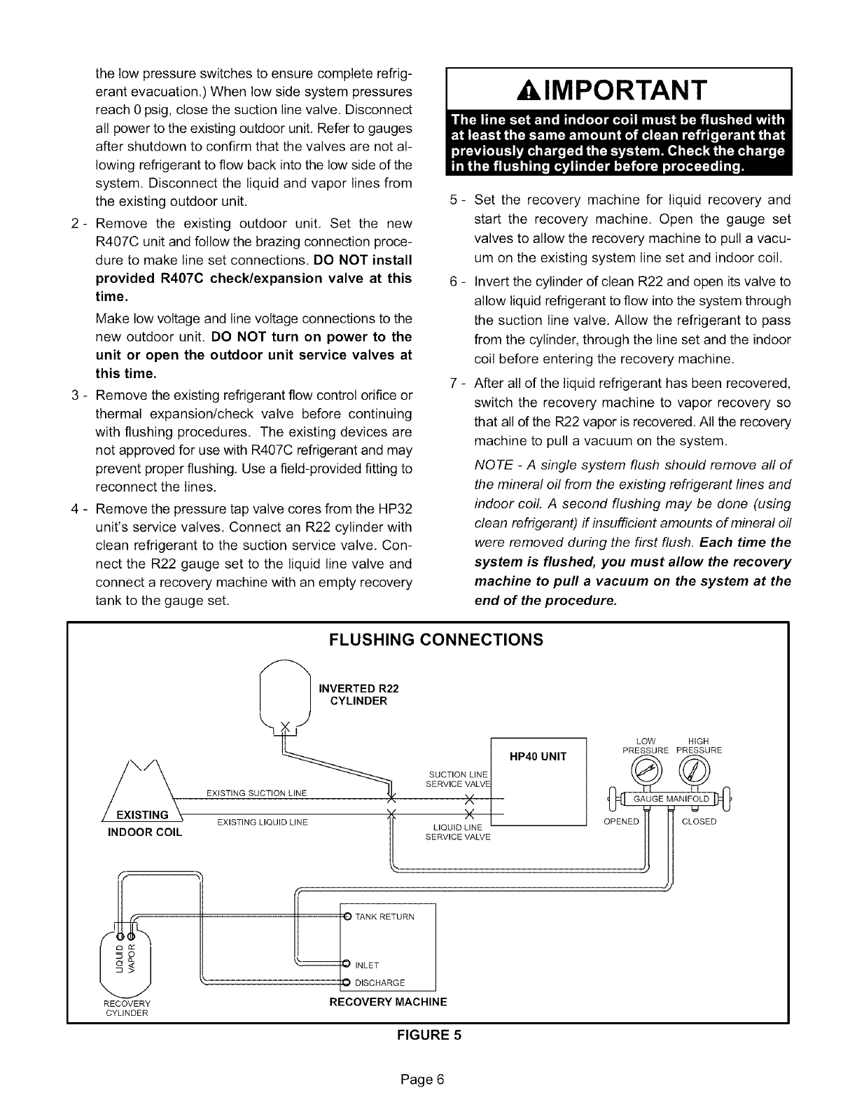
thelowpressureswitchestoensurecompleterefrig-
erantevacuation.)Whenlowsidesystempressures
reach0psig,closethesuctionlinevalve.Disconnect
allpowertotheexistingoutdoorunit,Refertogauges
aftershutdownto confirmthatthevalvesarenotal-
lowingrefrigeranttoflowbackintothelowsideofthe
system.Disconnecttheliquidandvaporlinesfrom
theexistingoutdoorunit,
2- Removethe existingoutdoorunit,Set the new
R407Cunitandfollowthebrazingconnectionproce-
duretomakelinesetconnections.DONOTinstall
providedR407Ccheck/expansionvalveat this
time.
Makelowvoltageandlinevoltageconnectionstothe
newoutdoorunit.DONOTturn on powerto the
unit or openthe outdoorunit servicevalvesat
thistime.
3- Removetheexistingrefrigerantflowcontrolorificeor
thermalexpansion/checkvalvebeforecontinuing
withflushingprocedures.Theexistingdevicesare
notapprovedforusewithR407Crefrigerantandmay
preventproperflushing,Useafield-providedfittingto
reconnectthelines.
4 - RemovethepressuretapvalvecoresfromtheHP32
unit'sservicevalves,ConnectanR22cylinderwith
cleanrefrigerantto thesuctionservicevalve,Con-
necttheR22gaugesettotheliquidlinevalveand
connecta recoverymachinewithanemptyrecovery
tankto thegaugeset,
5 -
_
_
A, IMPORTANT
Set the recovery machine for liquid recovery and
start the recovery machine, Open the gauge set
valves to allow the recovery machine to pull a vacu-
um on the existing system line set and indoor coil,
Invert the cylinder of clean R22 and open its valve to
allow liquid refrigerant to flow into the system through
the suction line valve. Allow the refrigerant to pass
from the cylinder, through the line set and the indoor
coil before entering the recovery machine,
After all of the liquid refrigerant has been recovered,
switch the recovery machine to vapor recovery so
that all of the R22 vapor is recovered, All the recovery
machine to pull a vacuum on the system,
NOTE -A single system flush should remove all of
the mineral oil from the existing refrigerant lines and
indoor coil. A second flushing may be done (using
clean refrigerant) if insufficient amounts of mineral oil
were removed during the first flush. Each time the
system is flushed, you must allow the recovery
machine to pull avacuum on the system at the
end of the procedure.
FLUSHING CONNECTIONS
EXISTING
INDOOR COIL
/_ INVERTED R22
JCYLINDER
EXISTING SU__
EXISTING LIQUID LINE _"
L
SUCTION LIN_t
SERVICE VALV
×
X
LIQUID LINE
SERVICE VALVE
HP40 UNIT
RECOVERY
CYLINDER
TANK RETURN
INLET
DISCHARGE
RECOVERY MACHINE
LOW HIGH
PRESSURE PRESSURE
FIGURE 5
Page 6
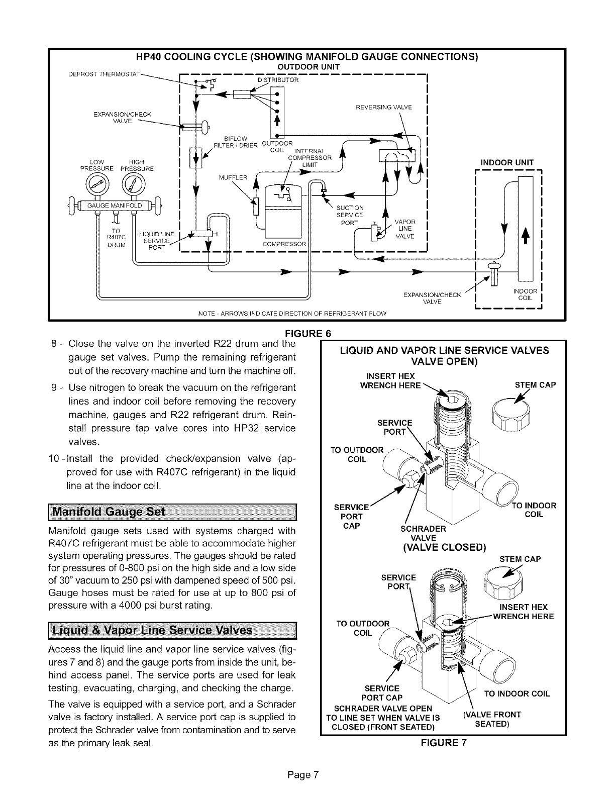
HP4O COOLING CYCLE (SHOWING MANIFOLD GAUGE CONNECTIONS)
OUTDOOR UNIT
DEFROSTTHERMOSTAT_,___
I
EXPANSION/CHECK I
VALVE _
LOW HIGH
PRESSURE PRESSURE
GAUGE MANIFOLD
TO LIQUID LINE
R407C SERVICE
DRUM PORT
DISTRIBUTOR
1_ _I_1"_ I REVERSING VALVE
FLOW _ '_,
© F,LT R/DR,EROUTDOOR )
CO,L,NTERNAL
,-]/ COMPRESSORE -
J/&M,T
SUCTION
SERVICE _ VAPOR
POR .._
COMPRESSOR ':,
k r""- _
EXPANSION/CHECK
VALVE
NOTE - ARROWS INDICATE DIRECTION OF REFRIGERANT FLOW
INDOOR UNIT
i
p
_(_ INDOOR
I COIL
L..... -I
FIGURE 6
8 - Close the valve on the inverted R22 drum and the
gauge set valves. Pump the remaining refrigerant
out of the recovery machine and turn the machine off.
9 - Use nitrogen to break the vacuum on the refrigerant
lines and indoor coil before removing the recovery
machine, gauges and R22 refrigerant drum. Rein-
stall pressure tap valve cores into HP32 service
valves.
10-Install the provided check/expansion valve (ap-
proved for use with R407C refrigerant) in the liquid
line at the indoor coil.
Manifold gauge sets used with systems charged with
R407C refrigerant must be able to accommodate higher
system operating pressures. The gauges should be rated
for pressures of 0-800 psi on the high side and a low side
of 30" vacuum to 250 psi with dampened speed of 500 psi.
Gauge hoses must be rated for use at up to 800 psi of
pressure with a 4000 psi burst rating.
Access the liquid line and vapor line service valves (fig-
ures 7 and 8) and the gauge ports from inside the unit, be-
hind access panel. The service ports are used for leak
testing, evacuating, charging, and checking the charge.
The valve is equipped with a service port, and a Schrader
valve is factory installed. A service port cap is supplied to
protect the Schrader valve from contamination and to serve
as the primary leak seal.
LIQUID AND VAPOR LINE SERVICE VALVES
VALVE OPEN)
INSERT HEX
WRENCH STEM CAP
SERVICE
PORT X
TO OUTDOOR
COIL
SERVICE'
PORT
CAP SCHRADER
VALVE
(VALVE CLOSED)
SERVICE
)INDOOR
COIL
STEM CAP
TO OUTDOOR
COIL
INSERT HEX
SERVICE
PORT CAP
SCHRADER VALVE OPEN
TO LINE SET WHEN VALVE IS
CLOSED (FRONT SEATED)
TO INDOOR COIL
(VALVE FRONT
SEATED)
FIGURE 7
Page 7
IMPORTANT
Accessing the Schrader Port:
1 - Remove service port cap with an adjustable wrench,
2 - Connect gauge to the service port.
3- When testing is completed, replace the service port
cap. Tighten finger tight, then tighten an additional 1/6
turn.
To Open Liquid or Vapor Line Service Valve:
1 - Remove the stem cap with an adjustable wrench,
2 - Use a service wrench with a hex-head extension to
back the stem out counterclockwise as far as pos-
sible.
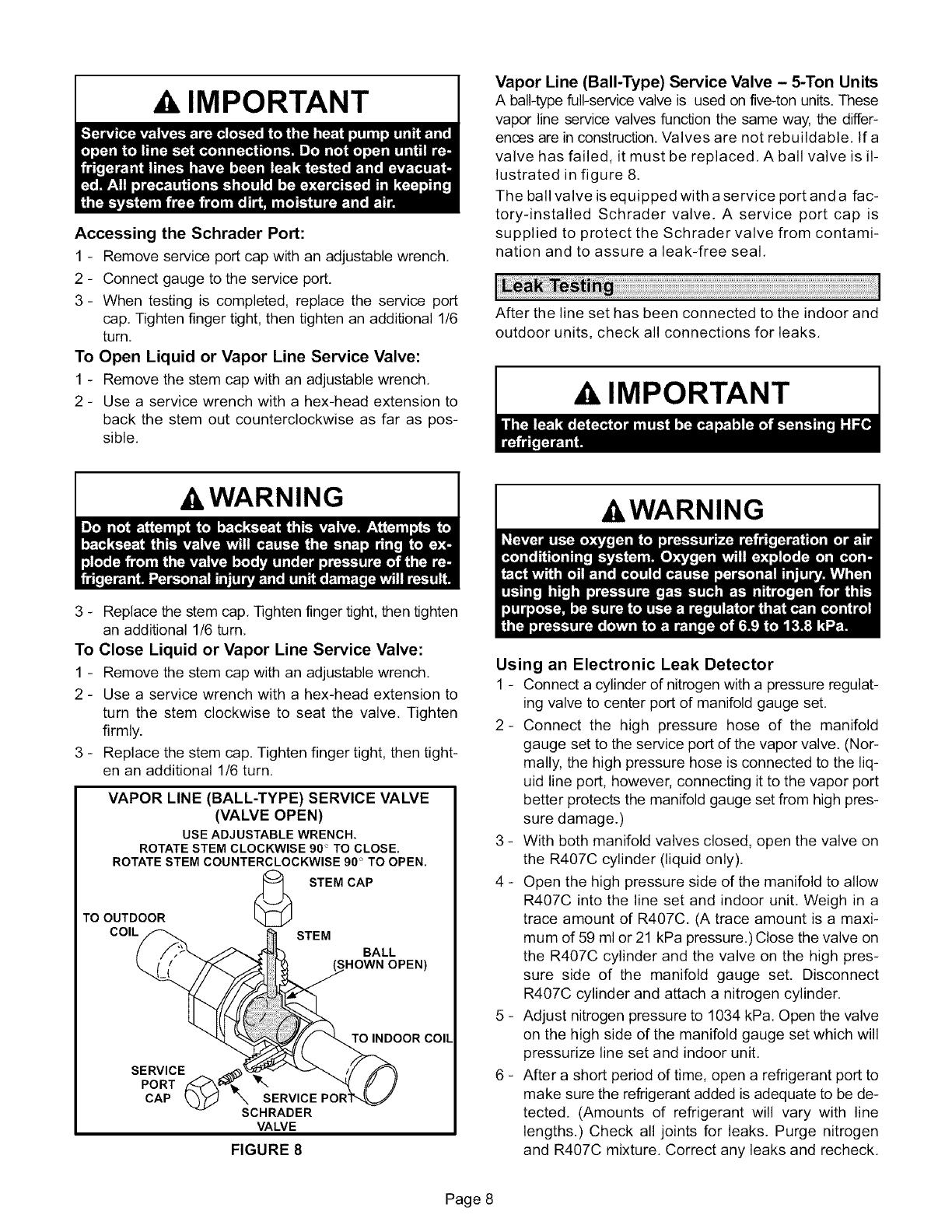
Vapor Line (Bali-Type) Service Valve - 5-Ton Units
A ball-type full-service valve is used on five-ton units. These
vapor line service valves function the same way, the differ-
ences are in construction. Valves are not rebuildable, Ifa
valve has failed, it must be replaced, A ball valve is il-
lustrated in figure 8.
The ball valve is equipped with a service port and a fac-
tory-installed Schrader valve. A service port cap is
supplied to protect the Schrader valve from contami-
nation and to assure a leak-free seal,
After the line set has been connected to the indoor and
outdoor units, check all connections for leaks,
IMPORTANT
&WARNING AkWARNING
3 - Replace the stem cap, Tighten finger tight, then tighten
an additional 1/6 turn,
To Close Liquid or Vapor Line Service Valve:
1 - Remove the stem cap with an adjustable wrench,
2 - Use a service wrench with a hex-head extension to
turn the stem clockwise to seat the valve, Tighten
firmly.
3 - Replace the stem cap, Tighten finger tight, then tight-
en an additional 1/6 turn,
TO OUTDOOR
COIL
VAPOR LINE (BALL-TYPE) SERVICE VALVE
(VALVE OPEN)
USE ADJUSTABLE WRENCH.
ROTATE STEM CLOCKWISE 90" TO CLOSE.
ROTATE STEM COUNTERCLOCKWISE 90" TO OPEN.
@ STEM CAP
STEM
BALL
SHOWN OPEN)
TO INDOOR COIL
SERVICE
PORT
CAP SERVICE POF
SCHRADER
VALVE
FIGURE 8
Using an Electronic Leak Detector
1 - Connect a cylinder of nitrogen with a pressure regulat-
ing valve to center port of manifold gauge set,
2- Connect the high pressure hose of the manifold
gauge set to the service port of the vapor valve, (Nor-
mally, the high pressure hose is connected to the liq-
uid line port, however, connecting it to the vapor port
better protects the manifold gauge set from high pres-
sure damage.)
3 - With both manifold valves closed, open the valve on
the R407C cylinder (liquid only),
4 - Open the high pressure side of the manifold to allow
R407C into the line set and indoor unit. Weigh in a
trace amount of R407C, (A trace amount is a maxi-
mum of 59 ml or 21 kPa pressure,) Close the valve on
the R407C cylinder and the valve on the high pres-
sure side of the manifold gauge set, Disconnect
R407C cylinder and attach a nitrogen cylinder.
5 - Adjust nitrogen pressure to 1034 kPa. Open the valve
on the high side of the manifold gauge set which will
pressurize line set and indoor unit,
6 - After a short period of time, open a refrigerant port to
make sure the refrigerant added is adequate to be de-
tected. (Amounts of refrigerant will vary with line
lengths.) Check all joints for leaks. Purge nitrogen
and R407C mixture. Correct any leaks and recheck,
Page 8
-&WARNING
gen cylinder with the pressure regulator set to 150
psig (1034 kPa) and purge the hose. Open the man-
ifold gauge valves to break the vacuum in the system.
Close the manifold gauge valves.
-&WARNING
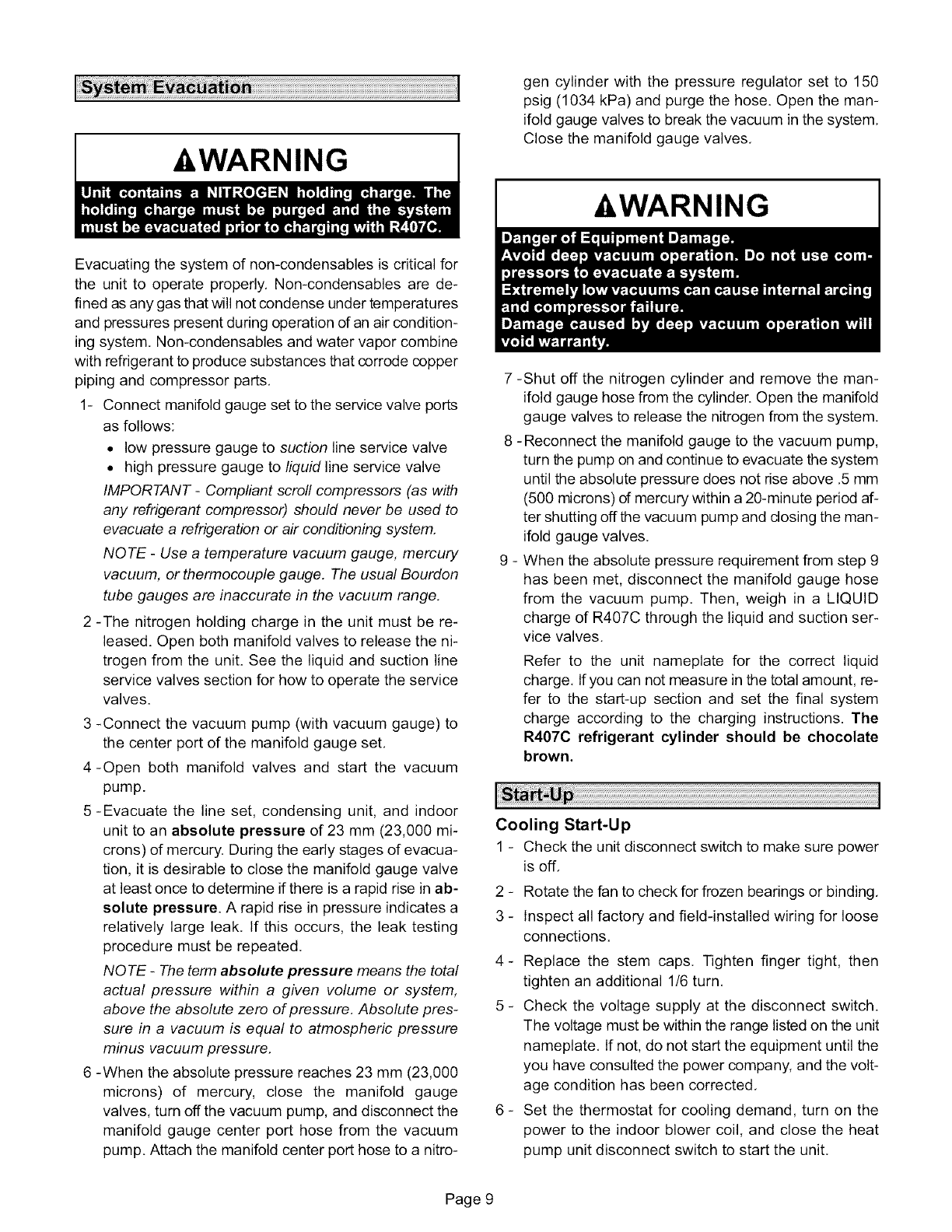
Evacuating the system of non-condensables is critical for
the unit to operate properly. Non-condensables are de-
fined as any gas that will not condense under temperatures
and pressures present during operation dan air condition-
ing system. Non-condensables and water vapor combine
with refrigerant to produce substances that corrode copper
piping and compressor parts.
1- Connect manifold gauge set to the service valve ports
as follows:
• low pressure gauge to suction line service valve
• high pressure gauge to liquid line service valve
IMPORTANT- Compliant scroll compressors (as with
any refrigerant compressor) should never be used to
evacuate a refrigeration or air conditioning system.
NOTE -Use a temperature vacuum gauge, mercury
vacuum, or thermocouple gauge. The usual Bourdon
tube gauges are inaccurate in the vacuum range.
2 -The nitrogen holding charge in the unit must be re-
leased. Open both manifold valves to release the ni-
trogen from the unit. See the liquid and suction line
service valves section for how to operate the service
valves.
3 -Connect the vacuum pump (with vacuum gauge) to
the center port of the manifold gauge set.
4-Open both manifold valves and start the vacuum
pump.
5-Evacuate the line set, condensing unit, and indoor
unit to an absolute pressure of 23 mm (23,000 mi-
crons) of mercury. During the early stages of evacua-
tion, it is desirable to close the manifold gauge valve
at least once to determine if there is a rapid rise in ab-
solute pressure. A rapid rise in pressure indicates a
relatively large leak. If this occurs, the leak testing
procedure must be repeated.
NOTE -The term absolute pressure means the total
actual pressure within a given volume or system,
above the absolute zero of pressure. Absolute pres-
sure in a vacuum is equal to atmospheric pressure
minus vacuum pressure.
6 -When the absolute pressure reaches 23 mm (23,000
microns) of mercury, close the manifold gauge
valves, turn off the vacuum pump, and disconnect the
manifold gauge center port hose from the vacuum
pump. Attach the manifold center port hose to a nitro-
7 -Shut off the nitrogen cylinder and remove the man-
ifold gauge hose from the cylinder. Open the manifold
gauge valves to release the nitrogen from the system.
8 -Reconnect the manifold gauge to the vacuum pump,
turn the pump on and continue to evacuate the system
until the absolute pressure does not rise above .5 mm
(500 microns) of mercury within a 20-minute period af-
ter shutting off the vacuum pump and dosing the man-
ifold gauge valves.
9 - When the absolute pressure requirement from step 9
has been met, disconnect the manifold gauge hose
from the vacuum pump. Then, weigh in a LIQUID
charge of R407C through the liquid and suction ser-
vice valves.
Refer to the unit nameplate for the correct liquid
charge. Ifyou can not measure in the total amount, re-
fer to the start-up section and set the final system
charge according to the charging instructions. The
R407C refrigerant cylinder should be chocolate
brown.
Cooling Start-Up
1 - Check the unit disconnect switch to make sure power
is off.
2 - Rotate the fan to check for frozen bearings or binding.
3 - Inspect all factory and field-installed wiring for loose
connections.
4- Replace the stem caps. Tighten finger tight, then
tighten an additional 1/6 turn.
5 - Check the voltage supply at the disconnect switch.
The voltage must be within the range listed on the unit
nameplate. If not, do not start the equipment until the
you have consulted the power company, and the volt-
age condition has been corrected.
6 - Set the thermostat for cooling demand, turn on the
power to the indoor blower coil, and close the heat
pump unit disconnect switch to start the unit.
Page 9
_Recheck the unit voltage while the unit is running.
The power must be within the range shown on the
unit nameplate, Check the amperage draw of the
unit. Refer to the unit nameplate for approximate
running amps,
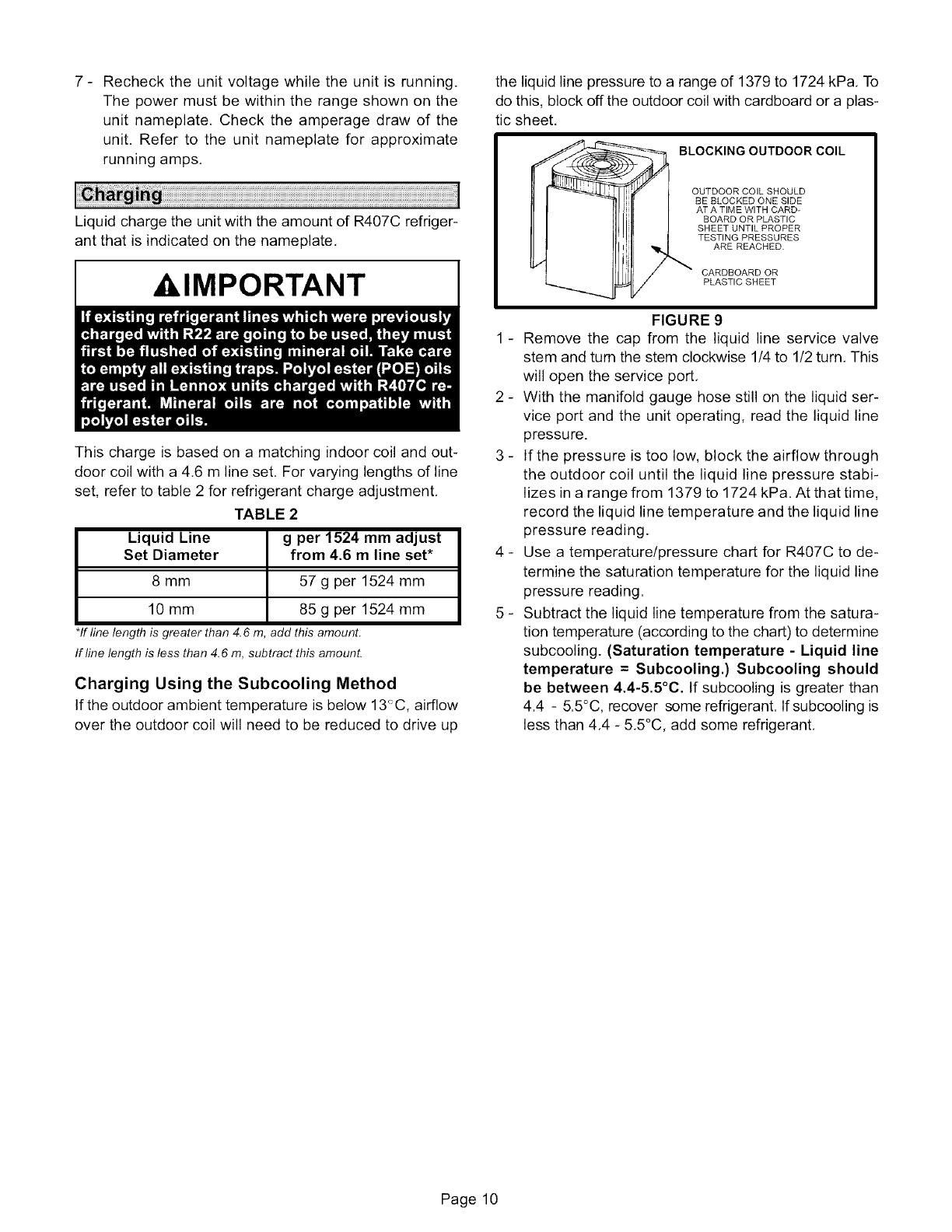
Liquid charge the unit with the amount of R407C refriger-
ant that is indicated on the nameplate.
,IMPORTANT
This charge is based on a matching indoor coil and out-
door coil with a 4.6 m line set, For varying lengths of line
set, refer to table 2 for refrigerant charge adjustment,
TABLE 2
Liquid Line
Set Diameter
8 mm
10 mm
*If line length is greater than 4.6
g per 1524 mm adjust
from 4.6 mline set*
57 g per 1524 mm
85 g per 1524 mm
add this amount.
If line length is less than 4.6 m, subtract this amounL
Charging Using the Subcooling Method
If the outdoor ambient temperature is below 13_C, airflow
over the outdoor coil will need to be reduced to drive up
the liquid line pressure to a range of 1379 to 1724 kPa, To
do this, block off the outdoor coil with cardboard or a plas-
tic sheet,
BLOCKING OUTDOOR COIL
OUTDOOR COIL SHOULD
BE BLOCKED ONE SIDE
AT A TIME WITH CARD-
BOARD OR PLASTIC
SHEET UNTIL PROPER
TESTING PRESSURES
ARE REACHED.
CARDBOARD OR
PLASTIC SHEET
FIGURE 9
1 - Remove the cap from the liquid line service valve
stem and turn the stem clockwise 1/4 to 1/2 turn, This
will open the service port,
2 - With the manifold gauge hose still on the liquid ser-
vice port and the unit operating, read the liquid line
pressure.
3 - If the pressure is too low, block the airflow through
the outdoor coil until the liquid line pressure stabi-
lizes in a range from 1379 to 1724 kPa, At that time,
record the liquid line temperature and the liquid line
pressure reading.
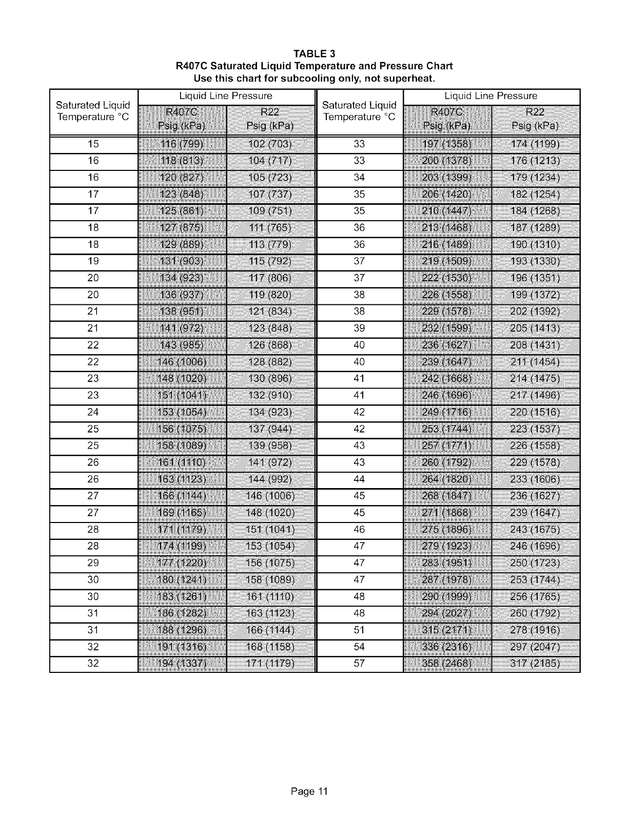
4 - Use a temperature/pressure chart for R407C to de-
termine the saturation temperature for the liquid line
pressure reading.
5 - Subtract the liquid line temperature from the satura-
tion temperature (according to the chart) to determine
subcooling. (Saturation temperature - Liquid line
temperature = Subcooling.) Subcooling should
be between 4.4-5.5°C. If subcooling is greater than
4.4 - 5.5°C, recover some refrigerant. Ifsubcooling is
less than 4,4 - 5,5°C, add some refrigerant,
Page 10
SaturatedLiquid
Temperature°C
15
16
16
17
17
18
18
19
2O
2O
21
21
22
22
23
23
24
25
25
26
26
27
27
28
28
29
30
30
31
31
32
32
TABLE 3
R407C Saturated Liquid Temperature and Pressure Chart
Use this chart for subcooling only, not superheat.
Liquid Line Pressure Liquid Line Pressure
Saturated Liquid
Temperature °C
33
33
34
35
35
36
36
37
37
38
38
39
40
40
41
41
42
42
43
43
44
45
45
46
47
47
47
48
48
51
54
57
Page 11
Filter Drier
Theunitisequippedwitha bifiowfilterdrier.Seefigure6.
If thefilterneedsto be replaced,orderanotherof the
samedesign.
Thermostat Operation
Someheatpumpthermostatsincorporateisolatingcon-
tactsandanemergencyheatfunction(whichincludesan
amberindicatinglight).Thethermostatis notincluded
withtheunitandmustbepurchasedseparately.
Emergency HeatFunction
Somethermostatshavean emergencyheatfunction.
Thisfeatureisapplicableonlytothosesystemsthathave
auxiliaryelectricheatstagedby outdoorthermostats.
Whenthethermostatis placedin theemergencyheat
position,theoutdoorunitcontrolcircuitis isolatedfrom
thepowersource,andfield-providedrelaysbypassthe
outdoorthermostats.Anamberindicatinglightsimulta-
neouslycomesontoremindthehomeownerthattheunit
isoperatingintheemergencyheatmode.
Emergencyheatisusuallyusedduringa heatpumpshut-
down.However,emergencyheatshouldalsobeusedfol-
lowinga poweroutageifthepowerhasbeenoffforover
anhour,andtheoutdoortemperatureisbelow10_C.The
systemshouldbeleftintheemergencyheatmodeforat
leastsixhoursto allowthecrankcaseheatersufficient
timetopreventcompressorfromslugging.
TheHP40defrostsystemincludestwocomponents:ade-
frostthermostatandadefrostcontrol.
Defrost Thermostat
Thedefrostthermostatis locatedontheliquidlinebe-
tweenthe check/expansionvalveandthe distributor,
Whendefrostthermostatsenses5,5°Corcooler,thether-
mostatcontactscloseandsenda signalto thedefrost
controlboardtostartthedefrosttiming,Italsoterminates
defrostwhentheliquidlinewarmsupto21°C.
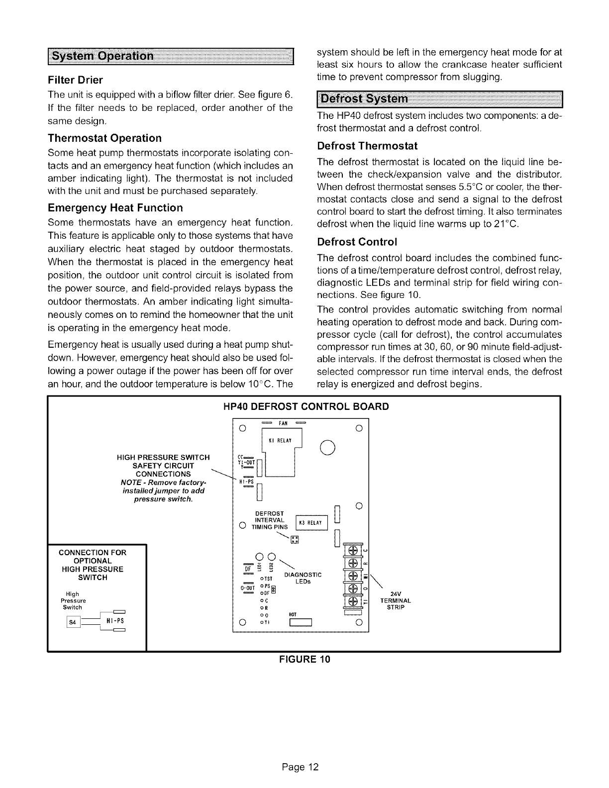
Defrost Control
Thedefrostcontrolboardincludesthecombinedfunc-
tionsofatime/temperaturedefrostcontrol,defrostrelay,
diagnosticLEDsandterminalstripfor fieldwiringcon-
nections.Seefigure10,
Thecontrolprovidesautomaticswitchingfromnormal
heatingoperationtodefrostmodeandback.Duringcom-
pressorcycle(callfor defrost),thecontrolaccumulates
compressorruntimesat30,60,or90minutefield-adjust-
ableintervals.Ifthedefrostthermostatisclosedwhenthe
selectedcompressorruntimeintervalends,thedefrost
relayisenergizedanddefrostbegins,
CONNECTION FOR
OPTIONAL
HIGH PRESSURE
SWITCH
High
Pressure
Switch
HIGH PRESSURE SWITCH
SAFETY CIRCUIT
CONNECTIONS
NOTE -Remove factory-
installed jumper to add
pressure switch.
HP40DEFROSTCONTROLBOARD
FAH
DEFROST _ O
INTERVAp_N_ _
OTIMING
DIAGNOSTIC
oTST LEDs
o.ou=,
oC
oR
o0Hot ECCC3
OoY_ [_ O
\
24V
TERMINAL
STRIP
FIGURE 10
Page 12
Defrost Control Timing Pins
Each timing pin selection provides a different accumu-
lated compressor run time period during one thermo-
stat run cycle, This time period must occur before a de-
frost cycle is initiated, The defrost interval can be ad-
justed to 30 (T1), 60 (T2), or 90 (T3) minutes, See figure
10. The defrost timing jumper is factory-installed to pro-
vide a 60-minute defrost interval, If the timing selector
jumper is not in place, the control defaults to a 90-min-
ute defrost interval. The maximum defrost period is 14
minutes and cannot be adjusted.
A TEST option is provided for troubleshooting, The TEST
mode may be started any time the unit is in the heat-
ing mode and the defrost thermostat is closed or
jumpered. If the jumper is in the TEST position at power-
up, the control will ignore the test pins. When the jumper is
placed across the TEST pins for two seconds, the control
will enter the defrost mode. If the jumper is removed be-
fore an additional 5-second period has elapsed (7 sec-
onds total), the unit will remain in defrost mode until the
defrost thermostat opens or 14 minutes have passed, If
the jumper is not removed until after the additional 5-sec-
ond period has elapsed, the defrost will terminate and the
test option will not function again until the jumper is re-
moved and re-applied,
Pressure Switch Circuit
The defrost control incorporates a pressure switch circuit
that allows the application of an optional high pressure
switch, See figure 10, During a demand cycle, the defrost
control will lock out the unit if the optional high pressure
switch opens. The diagnostic LEDs will display a pattern
for an open high pressure switch, See table 3, The unit will
remain locked out until the switch resets or is reset.
Remove the factory-installed jumper before connecting
the optional high pressure switch to the control board,
NOTE -If not using a pressure switch, the factory-
installed jumper wire must be connected,
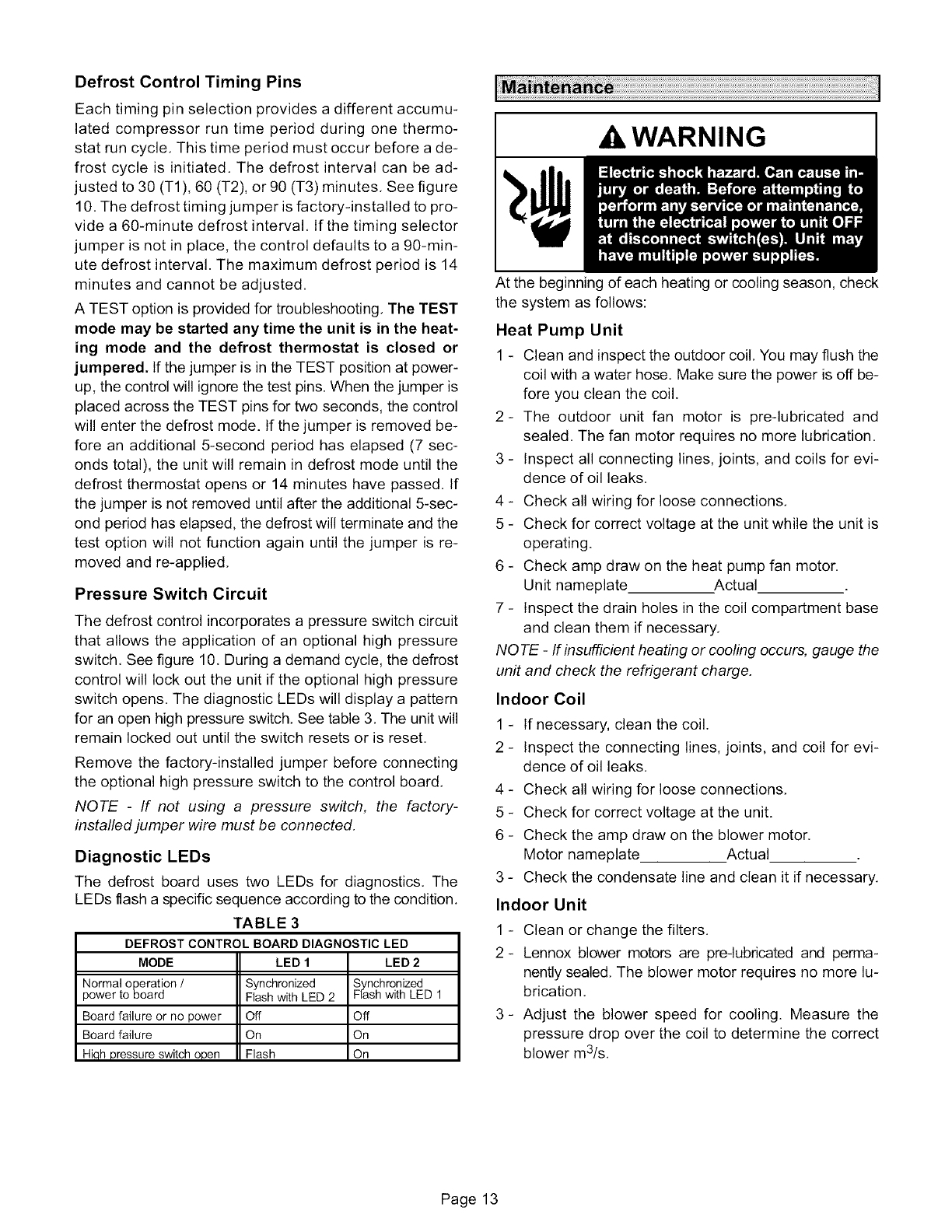
Diagnostic LEDs
The defrost board uses two LEDs for diagnostics. The
LEDs flash a specific sequence according to the condition.
TABLE 3
DEFROST CONTROL BOARD DIAGNOSTIC LED
MODE LED 1 LED 2
Normal operation /Synchronized Synchronized
power to board Flash with LED 2 Flash with LED 1
Board failure or no power Off Off
Board failure On On
Hiqh pressure switch open Flash On
_WARNING
At the beginning of each heating or cooling season, check
the system as follows:
Heat Pump Unit
1 - Clean and inspect the outdoor coil, You may flush the
coil with a water hose, Make sure the power is off be-
fore you clean the coil.
2- The outdoor unit fan motor is pre-lubricated and
sealed, The fan motor requires no more lubrication,
3 - Inspect all connecting lines, joints, and coils for evi-
dence of oil leaks,
4 - Check all wiring for loose connections,
5 - Check for correct voltage at the unit while the unit is
operating.
6 - Check amp draw on the heat pump fan motor.
Unit nameplate Actual
7 - Inspect the drain holes in the coil compartment base
and clean them if necessary,
NOTE -If insufficient heating or cooling occurs, gauge the
unit and check the refrigerant charge.
Indoor Coil
1 - If necessary, clean the coil.
2 - Inspect the connecting lines, joints, and coil for evi-
dence of oil leaks,
4 - Check all wiring for loose connections,
5 - Check for correct voltage at the unit.
6 - Check the amp draw on the blower motor.
Motor nameplate Actual
3 - Check the condensate line and clean it if necessary,
Indoor Unit
1 - Clean or change the filters,
2- Lennox blower motors are pre-lubricated and perma-
nently sealed, The blower motor requires no more lu-
brication,
3- Adjust the blower speed for cooling. Measure the
pressure drop over the coil to determine the correct
blower m3/s,
Page 13
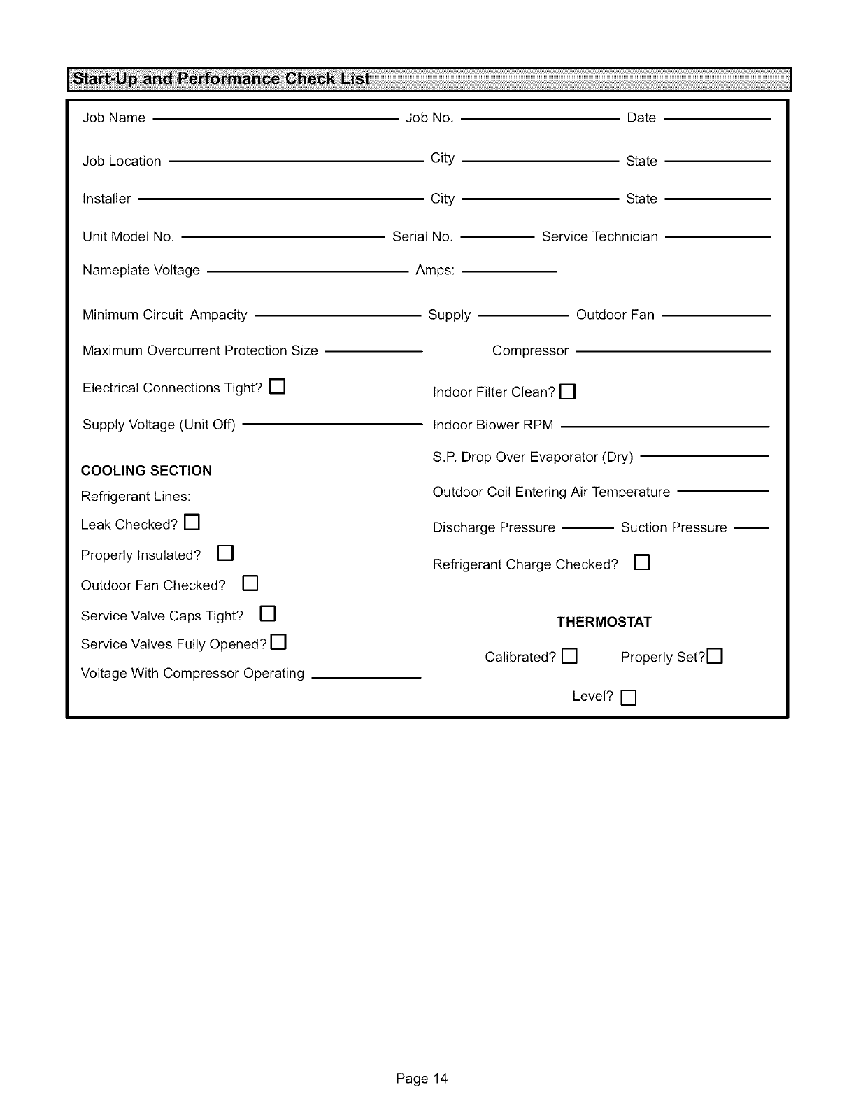
JobName
JobLocation
Installer
UnitModelNo,
NameplateVoltage
JobNo.
City
City
SerialNo.
Amps:
MinimumCircuitAmpacity
MaximumOvercurrentProtectionSize
ElectricalConnectionsTight?[]
SupplyVoltage(UnitOff)
Date
State
State
ServiceTechnician
COOLINGSECTION
RefrigerantLines:
LeakChecked?[]
ProperlyInsulated?[]
OutdoorFanChecked? []
ServiceValveCapsTight? []
ServiceValvesFullyOpened?[]
VoltageWithCompressorOperating
Supply OutdoorFan
Compressor
IndoorFilterClean?[]
IndoorBlowerRPM
S.RDropOverEvaporator(Dry)
OutdoorCoilEnteringAirTemperature
DischargePressure SuctionPressure
RefrigerantChargeChecked? []
THERMOSTAT
Calibrated?[] ProperlySet?[]
Level?[]
Page14

Page15

LENNOX
Lennox Industries
RO. Box 174, Westgate Interchange,
Northampton NN5 5AG
Telephone: 01604 591159
Facsimile: 01604 587536
Page 16
