LENNOX Air Conditioner/heat Pump(outside Unit) Manual L0806499
User Manual: LENNOX LENNOX Air conditioner/heat pump(outside unit) Manual LENNOX Air conditioner/heat pump(outside unit) Owner's Manual, LENNOX Air conditioner/heat pump(outside unit) installation guides
Open the PDF directly: View PDF ![]() .
.
Page Count: 20
,t_2006 Lennox industries Inc,
Dallas, Texas, USA
WARNING
AIMPORTANT
CAUTION
INSTALLATION
INSTRUCTIONS
SPA Units
SPA036H4 (3 Ton)
SPA048H4 (4 Ton)
SPA060H4 (5 Ton)
S-CLASS " HEAT PUMP UNITS
504,867M
06/06
Supersedes 03/06
)puTeChnical
blications
Litho U.S.A.
SPA Outdoor Unit ............................. 1
Shipping and Packing List ...................... 1
General Information ........................... 1
Unit Dimensions ............................... 2
Parts Arrangement ............................ 2
Setting the Unit ............................... 3
Electrical ..................................... 4
Refrigerant Piping ............................. 6
Refrigerant Metering Device .................... 8
Flushing Existing Line Set & Indoor Coil .......... 8
Manifold Gauge Set ........................... 10
Service Valves ................................ 10
Leak Testing .................................. 11
Evacuation ................................... 12
Start-Up ...................................... 12
Refrigerant Charging ........................... 13
System Operation ............................. 16
Defrost System ............................... 17
Maintenance .................................. 18
Optional Accessories .......................... 18
Start-Up and Performance Check List ............ 20
RETAIN THESE INSTRUCTIONS
FOR FUTURE REFERENCE
The S-Class '" SPA outdoor units use R-410A HFC refrig-
erant. This unit must be installed with a matching indoor
coil and line set as outlined in the Lennox Engineering
Handbook. SPA outdoor units are designed for use in ex-
pansion valve (TXV) systems only. They are not designed
to be used with other refrigerant flow control devices. The
Lennox Engineering Handbook lists indoor TXV kits that
must be ordered separately.
These instructions are intended as a general guide and do
not supersede local codes in any way. Consult authorities
who have jurisdiction before installation.
Assembled SPA outdoor unit
Grommets (for liquid and vapor lines)
Check equipment for shipping damage. If you find any
damage, immediately contact the last carrier.
06/06
IIIIIIIIIIIIIIIIIIIIIIIIIIIIHIIIIIIII Page 1 504,867M
IIIIIIIIIIIIIIIIIIIIIIIIIIIIIIIIIIIIIIIIIIIIIIIIII
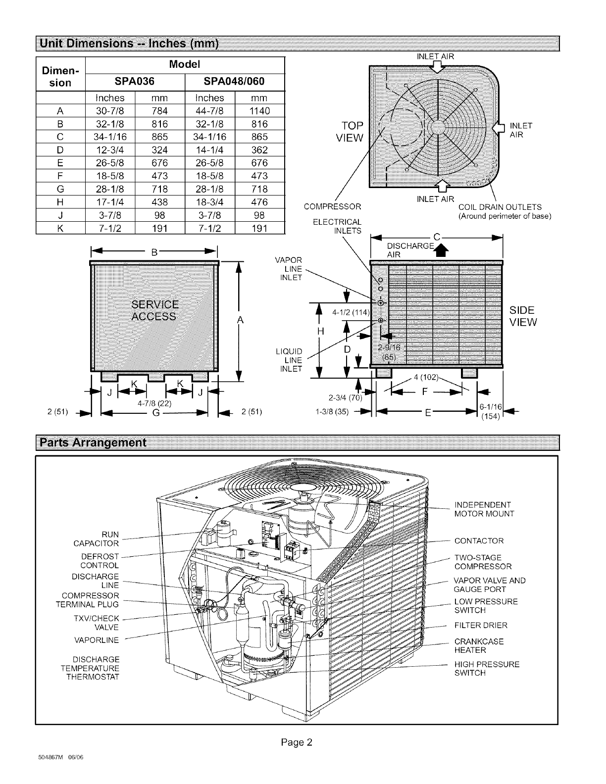
Model
Dimen-
sion SPA036 SPA048/060
Inches mm Inches mm
A 30-7/8 784 44-7/8 1140
B 32-1/8 816 32-1/8 816
C 34-1/16 865 34-1/16 865
D 12-3/4 324 14-1/4 362
E 26-5/8 676 26-5/8 676
F 18-5/8 473 18-5/8 473
G 28-1/8 718 28-1/8 718
H 17-1/4 438 18-3/4 476
J 3-7/8 98 3-7/8 98
K 7-1/2 191 7-1/2 191
A
2 (51) -- G2 (51)
INLETAIR
TOP INLET
VIEW AIR
VAPOR
INLET
LIQUID
LINE
INLET
INLETAIR
COMPRESSOR
ELECTRICAL
INLETS
X _ C r
DISCHARGEd&.
AIR BB
_" 1/2(114) 1: .......................................................................................................................................
4-
T_
n
:: :__::_:;;................................................................
A 1102). I I I
2-3/4(70) F ----'1_"_ b
1-3/8 (35) _ _ 16-1/161
I:: "Yl (154)
COIL DRAIN OUTLETS
(Around perimeter of base)
SIDE
VIEW
RUN
CAPACITOR
DEFROST
CONTROL
DISCHARGE
LINE
COMPRESSOR
TERMINAL PLUG
TXV/CHECK
VALVE
VAPORLINE
DISCHARGE
TEMPERATURE
THERMOSTAT
INDEPENDENT
MOTOR MOUNT
CONTACTOR
TWO-STAGE
COMPRESSOR
VAPOR VALVE AND
GAUGE PORT
LOW PRESSURE
SWITCH
FILTER DRIER
CRANKCASE
HEATER
HIGH PRESSURE
SWITCH
504867M 06/06
Page 2
WARNING
CAUTION
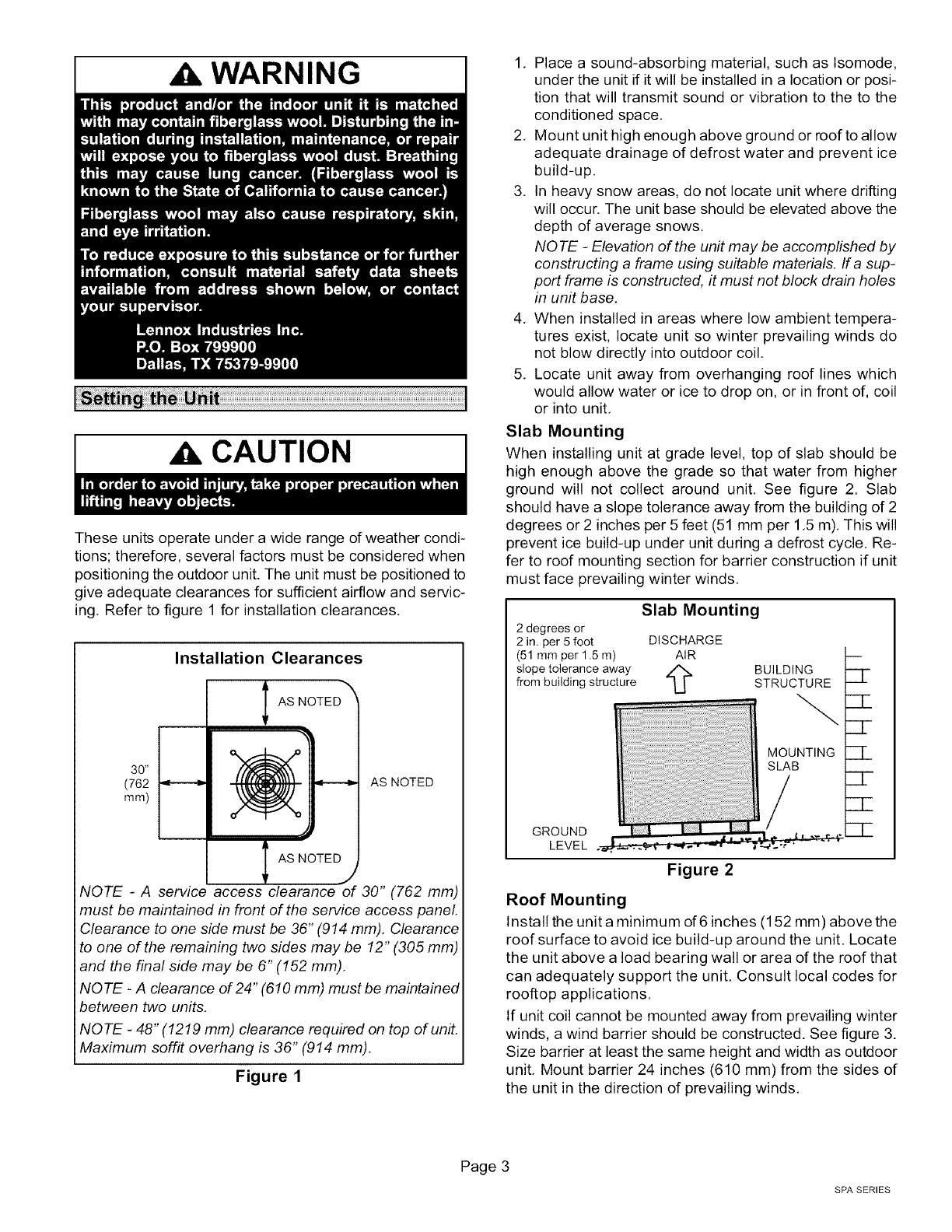
These units operate under a wide range of weather condi-
tions; therefore, several factors must be considered when
positioning the outdoor unit. The unit must be positioned to
give adequate clearances for sufficient airflow and servic-
ing, Refer to figure 1 for installation clearances.
Installation Clearances
I AS NOTED TM
36" _}
(762 _ AS NOTED
mm)
I AS NOTEDj
NOTE -A service access clearance of 30" (762 mm)
must be maintained in front of the service access panel.
Clearance to one side must be 36" (914 mm). Clearance
to one of the remaining two sides may be 12" (305 mm)
and the final side may be 6" (152 mm).
NO TE -A clearance of 24" (610 mm) must be maintained
between two units.
NOTE -48" (1219 mm) clearance required on top of unit.
Maximum soffit overhang is 36" (914 mm).
Figure 1
1, Place a sound-absorbing material, such as Isomode,
under the unit if it will be installed in a location or posi-
tion that will transmit sound or vibration to the to the
conditioned space.
2, Mount unit high enough above ground or roof to allow
adequate drainage of defrost water and prevent ice
build-up,
3, In heavy snow areas, do not locate unit where drifting
will occur. The unit base should be elevated above the
depth of average snows,
NOTE -Elevation of the unit may be accomplished by
constructing a frame using suitable materials. If a sup-
port frame is constructed, it must not block drain holes
in unit base.
4, When installed in areas where low ambient tempera-
tures exist, locate unit so winter prevailing winds do
not blow directly into outdoor coil.
5, Locate unit away from overhanging roof lines which
would allow water or ice to drop on, or in front of, coil
or into unit,
Slab Mounting
When installing unit at grade level, top of slab should be
high enough above the grade so that water from higher
ground will not collect around unit, See figure 2. Slab
should have a slope tolerance away from the building of 2
degrees or 2 inches per 5 feet (51 mm per 1,5 m), This will
prevent ice build-up under unit during a defrost cycle. Re-
fer to roof mounting section for barrier construction if unit
must face prevailing winter winds,
Slab Mounting
2 degrees or
2 in. per 5 foot DISCHARGE
(51 mm per 1.5 m) AIR
slope tolerance away A
from building structure -L[ BUILDING
STRUCTURE
GROUND
LEVEL
Figure 2
:21-
ZZ-
CL
CZ-
Roof Mounting
Install the unit a minimum of 6 inches (152 mm) above the
roof surface to avoid ice build-up around the unit. Locate
the unit above a load bearing wall or area of the roof that
can adequately support the unit, Consult local codes for
rooftop applications.
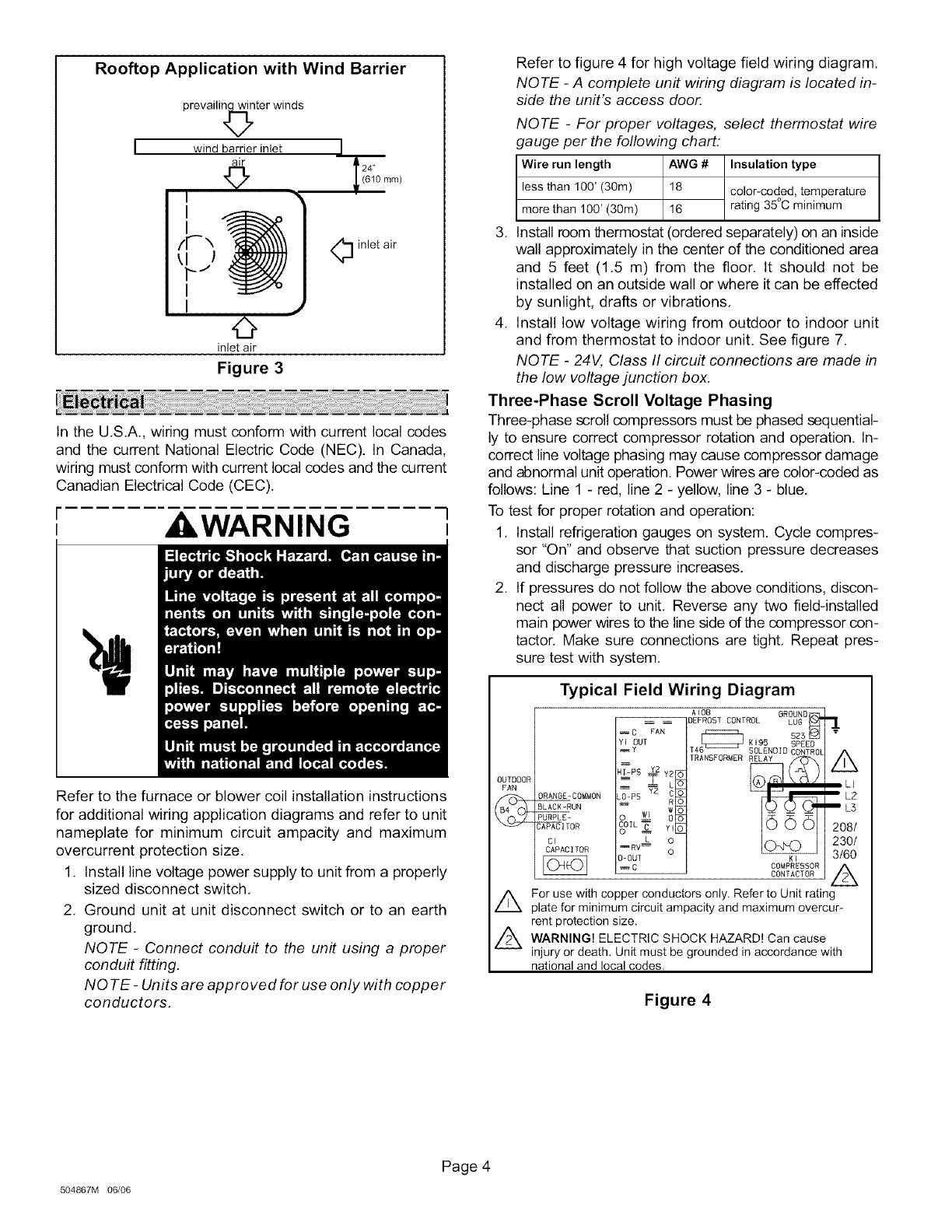
If unit coil cannot be mounted away from prevailing winter
winds, a wind barrier should be constructed. See figure 3.
Size barrier at least the same height and width as outdoor
unit, Mount barrier 24 inches (610 mm) from the sides of
the unit in the direction of prevailing winds,
Page 3
SPA SERIES
Rooftop Application with Wind Barrier
prevailir_Rer winds
wind barrier inlet
air
©
I
1
/r',
k_J
I
I •
©
inlet air
Figure 3
1
24"
(610 ram)
O inlet air
In the U.S.A., wiring must conform with current local codes
and the current National Electric Code (NEC). In Canada,
wiring must conform with current local codes and the current
Canadian Electrical Code (CEC).
WARNING l,
Refer to the furnace or blower coil installation instructions
for additional wiring application diagrams and refer to unit
nameplate for minimum circuit ampacity and maximum
overcurrent protection size.
1. Install line voltage power supply to unit from a properly
sized disconnect switch.
2. Ground unit at unit disconnect switch or to an earth
ground.
NOTE -Connect conduit to the unit using a proper
conduit fitting.
NO TE -Units are approved for use only with copper
conductors.
Refer to figure 4 for high voltage field wiring diagram.
NOTE -A complete unit wiring diagram is located in-
side the unit's access door.
NOTE -For proper voltages, select thermostat wire
gauge per the following chart:
Wire run length AWG # Insulation type
less than 100' (30m) 18 color-coded, temperature
more than 100' (30m) 16 rating 35°C minimum
3. Install room thermostat (ordered separately) on an inside
wall approximately in the center of the conditioned area
and 5 feet (1.5 m) from the floor. It should not be
installed on an outside wall or where it can be effected
by sunlight, drafts or vibrations.
4. Install low voltage wiring from outdoor to indoor unit
and from thermostat to indoor unit. See figure 7.
NOTE - 24V, Class II circuit connections are made in
the low voltage junction box.
Three-Phase Scroll Voltage Phasing
Three-phase scroll compressors must be phased sequential-
ly to ensure correct compressor rotation and operation. In-
correct line voltage phasing may cause compressor damage
and abnormal unit operation. Power wires are color-coded as
follows: Line 1 - red, line 2 - yellow, line 3 - blue.
To test for proper rotation and operation:
1. Install refrigeration gauges on system. Cycle compres-
sor "On" and observe that suction pressure decreases
and discharge pressure increases.
2. If pressures do not follow the above conditions, discon-
nect all power to unit. Reverse any two field-installed
main power wires to the line side of the compressor con-
tactor. Make sure connections are tight. Repeat pres-
sure test with system.
Typical Field Wiring Diagram
A 108 BROUND
_ DEFROST CONTROL LU6 _ "_C FAN
OUT _ sz_ "
K 195 SPEED
OUTDOOR LLI
rAN LZ
/I _ ORAN6E-COM_ON _-PS Y2
PURPLE =
\_'_ C_]TOR ?[L _ Yl 2081
cI o230/
CAPACITOR =RV_---L o3/60
-0UT K' A
CCOMPRESSOR
CONTACTOR
For use with copper conductors only Refer to Unit rating
plate for minimum circuit ampacity and maximum overcur-
rent protection size.
A ARNING! ELECTRIC SHOCK HAZARD! Can cause
injury or death. Unit must be grounded in accordance with
national and local codes.
Figure 4
504867M 06/06
Page 4
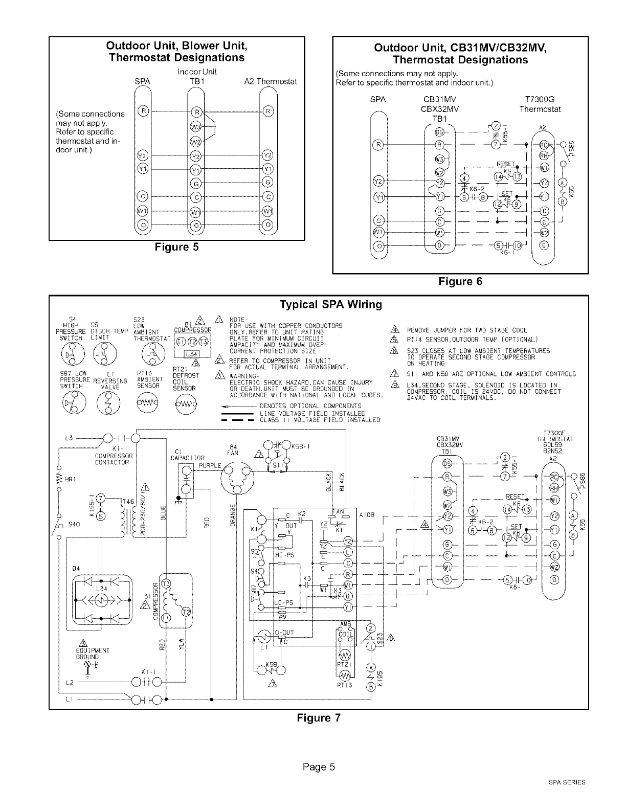
Outdoor Unit, Blower Unit,
Thermostat Designations
Indoor Unit
SPA TB1 A2 Thermostat
(Some connections
may not apply.
Refer to specific
thermostat and in-
door unit,) @--
©--
©--
@--
©--
©E
GE ©1
@E @1
Figure 5
Outdoor Unit, CB31MV/CB32MV,
Thermostat Designations
(Some connections may not apply,
Refer to specific thermostat and indoor unit.)
SPA T7300G
_ Thermostat
®1
@1
@1
@1
©1
©1
CB31MV
CBX32MV
TB1
@-
I _>
I @-
]
I
A2
Figure 6
$4 SZ3
HiGH $5 LOW
PRESSURE DISCH TEMP AMBIENT
SWITCH LIMIT
©©
$87 LOW LI
PRESSURE REVERSING
SWITCH VALVE
©@
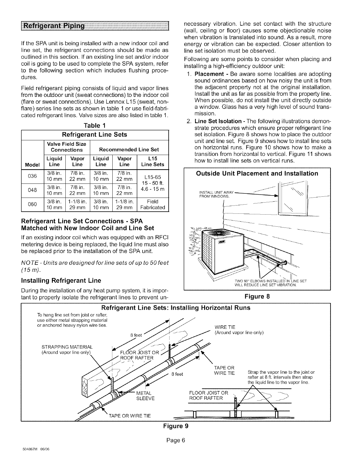
Typical SPA Wiring
DI_ z_ MOTE-
FOR USE WITH COPPER CONDUCTORS
COMPRESSOR ONLY,REFER TO UNIT RATING
THERMOSTAT If¢7_,#_,/_%_I PLATE FOR MINIMUM CIRCUIT
AMPACITY AND MAXIMUM OVER-
CURRENT PROTECTION SIZE
z:_ Z_ REFER TO COMPRESSOR IN UNIT
RT21 A FOR ACTUAL TERMINAL ARRANGEMENT.
RTIS DEFROST _ WARNING-
AMBIENT COIL ELECTRIC SHOCK HAZARD,CAN CAUSE INJURY
SENSOR SENSOR OR DEATH,UNIT MUST BE GROUNDED IN
/_ ACCORDANCE WITH NATIONAL AND LOCAL CODES,
-,,e-_DENOTES OPTIONAL COMPONENTS
-- LINE VOLTAGE FIELD INSTALLED
-- -- -- CLASS II VOLTAGE FIELD INSTALLED
Z_ REMOVE JUMPER FOR TWO STAGE COOL
Z_ RTI4 SENSOR,OUTDOOR TEMP (OPTIONAL}
Z_ $25 CLOSES AT LOW AMBIENT TEMPERATURES
TO OPERATE SECOND STAGE COMPRESSOR
ON HEATING
z_ SII AND K58 ARE OPTIONAL LOW AMBIENT CONTROLS
Z_ L34,SECOND STAGE, SOLENOID IS LOCATED IN
COMPRESSOR. COIL IS 24VOC, DO NOT CONNECT
24VAO TO COIL TERMINALS.
L_ ,C_
HR I CONTACT0 I A
_ _TA6rl _ L
)"L _
BE_
_ 8
EQUIPMENT c_
GROUND
KI-I
L_ _
CE
CAPACITOR
Be
FAN
LE
WC K2 AN
(I y KI
+________]RV AMB
rIo£
c......................................I1 ?
z_ RTI3
F --
]
]
_y;i
CB31MV
CBXS2MV
TBI
@-- -- __
T7300F
THERMOSTAT
60L59
82N52
A_._
(B)
--{G>I
-{cYqs
-@ [
Figure 7
Page 5
SPA SERIES
If the SPA unit is being installed with a new indoor coil and
line set, the refrigerant connections should be made as
outlined in this section. If an existing line set and/or indoor
coil is going to be used to complete the SPA system, refer
to the following section which includes flushing proce-
dures,
Field refrigerant piping consists of liquid and vapor lines
from the outdoor unit (sweat connections) to the indoor coil
(flare or sweat connections). Use Lennox L15 (sweat, non-
flare) series line sets as shown in table 1 or use field-fabri-
cated refrigerant lines. Valve sizes are also listed in table 1.
Table 1
Refrigerant Line Sets
Model
036
048
060
Valve Field Size
Connections
Liquid Vapor
Line Line
3t8 in. 7/8 in.
10 mm 22 mm
3t8 in. 7/8 in.
10 mm 22 mm
3t8in. 1-1/8in.
10 mm 29 mm
Recommended Line Set
Liquid Vapor
Line Line
3/8 in. 7/8 in.
10 mm 22 mm
3/8 in. 7/8 in.
10 mm 22 mm
3/8 in. 1-1/8 in.
10 mm 29 mm
L15
Line Sets
L15-65
15-50 ft.
4.6-15m
Field
Fabricated
Refrigerant Line Set Connections - SPA
Matched with New Indoor Coil and Line Set
If an existing indoor coil which was equipped with an RFCI
metering device is being replaced, the liquid line must also
be replaced prior to the installation of the SPA unit,
NOTE -Units are designed for line sets of up to 50 feet
(15 m).
Installing Refrigerant Line
During the installation of any heat pump system, it is impor-
tant to properly isolate the refrigerant lines to prevent un-
necessary vibration. Line set contact with the structure
(wall, ceiling or floor) causes some objectionable noise
when vibration is translated into sound, As a result, more
energy or vibration can be expected, Closer attention to
line set isolation must be observed,
Following are some points to consider when placing and
installing a high-efficiency outdoor unit:
1. Placement - Be aware some localities are adopting
sound ordinances based on how noisy the unit is from
the adjacent property not at the original installation.
Install the unit as far as possible from the property line.
When possible, do not install the unit directly outside
a window. Glass has a very high level of sound trans-
mission,
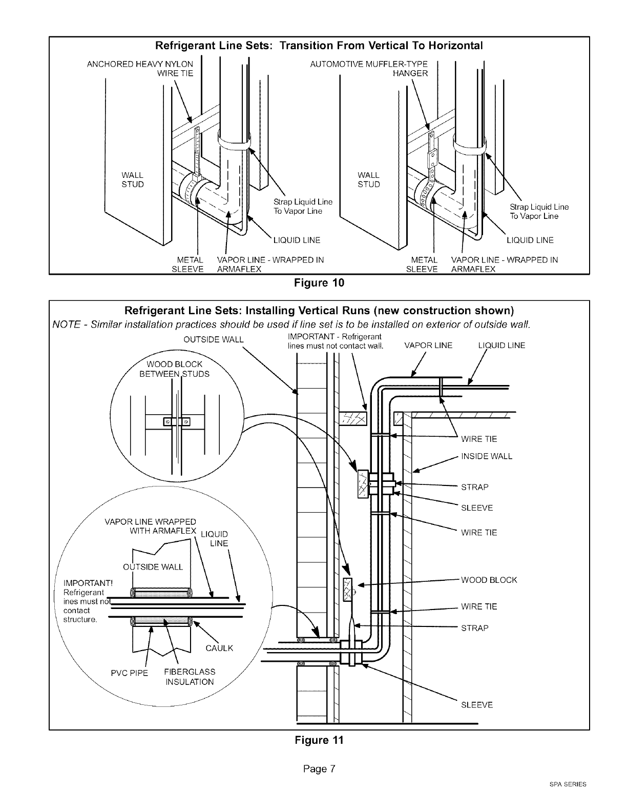
2. Line Set Isolation - The following illustrations demon-
strate procedures which ensure proper refrigerant line
set isolation. Figure 8 shows how to place the outdoor
unit and line set. Figure 9 shows how to install line sets
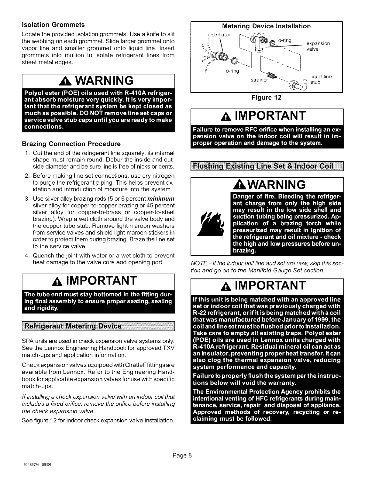
on horizontal runs. Figure 10 shows how to make a
transition from horizontal to vertical. Figure 11 shows
how to install line sets on vertical runs.
Outside Unit Placement and Installation
"2 ,,
J
INSTALL UNIT AWAY _
FROM WINDOWS.
TWO 90 ° ELBOWS INSTALLED IN LINE SET
WILL REDUCE LINE SET VIBRATION.
Figure 8
Refrigerant Line Sets: Installing Horizontal Runs
To hang line set from joist or rafter,
use either metal strapping material
or anchored heavy nylon wire ties. WIRE TIE
8 feet (Around vapor line only)
STRAPPING MATERIAL
(Around vapor line only), FLOOR JOIST OR
ROOF RAFTER
TAPE OR
8 feet WIRE TIE
METAL FLOOR JOIST OR ,
SLEEVE ROOF RAFTER
Strap the vapor line to the joist or
rafter at 8 ft. intervals then strap
the liquid line to the vapor line.
TAPE OR WIRE TIE N
Figure 9
504867M 06/06
Page 6
Refrigerant Line Sets: Transition From Vertical To Horizontal
ANCHORED HEAVY NYLON AUTOMOTIVE MUFFLER-TYPE
WIRE TIE HANGER
WALL WALL
STUD STUD
Strap Liquid Line Strap Liquid Line
To Vapor Line To Vapor Line
LIQUID LINE LIQUID LINE
METAL VAPOR LINE - WRAPPED IN METAL VAPOR LINE - WRAPPED IN
SLEEVE ARMAFLEX SLEEVE ARMAFLEX
Figure 10
Refrigerant Line Sets: Installing Vertical Runs (new construction shown)
NO TE -Similar installation practices should be used if line set is to be installed on exterior of outside wall.
OUTSIDE WALL IMPORTANT - Refrigerant
lines must not contact wall. VAPOR LINE LI UID LINE
VAPOR LINE WRAPPED
WITH ARMAFLEX LIQUID
[_--'"_ _- LINE
o \
IMPORTANT!
Refrigerant
ines must not
contact
structure.
PVC PIPE FIBERGLASS
INSULATION
-_. WIRE TIE
_- INSIDE WALL
-- STRAP
SLEEVE
_- WIRE TIE
---.--.----WOOD BLOCK
.___---- WIRE TIE
STRAP
SLEEVE
Figure 11
Page 7
SPA SERIES
Isolation Grommets
Locate the provided isolation grommets. Use a knife to slit
the webbing on each grommet. Slide larger grommet onto
vapor line and smaller grommet onto liquid line. Insert
grommets into mullion to isolate refrigerant lines from
sheet metal edges,
WARNING I
Brazing Connection Procedure
1, Cut the end of the refrigerant line squarely; its internal
shape must remain round, Debur the inside and out-
side diameter and be sure line is free of nicks or dents,
2, Before making line set connections, use dry nitrogen
to purge the refrigerant piping. This helps prevent ox-
idation and introduction of moisture into the system,
3, Use silver alloy brazing rods (5 or 6 percent minimum
silver alloy for copper-to-copper brazing or 45 percent
silver alloy for copper-to-brass or copper-to-steel
brazing). Wrap a wet cloth around the valve body and
the copper tube stub. Remove light maroon washers
from service valves and shield light maroon stickers in
order to protect them during brazing. Braze the line set
to the service valve,
4. Quench the joint with water or a wet cloth to prevent
heat damage to the valve core and opening port,
IMPORTANT
SPA units are used in check expansion valve systems only.
See the Lennox Engineering Handbook for approved TXV
match-ups and application information,
Check expansion valves equipped with Chatleff fittings are
available from Lennox. Refer to the Engineering Hand-
book for applicable expansion valves for use with specific
match-ups,
If installing a check expansion valve with an indoor coil that
includes a fixed orifice, remove the orifice before installing
the check expansion valve.
See figure 12 for indoor check expansion valve installation,
Metering Device Installation
distributor
o-ring expansion
valve
// o-ring [""" "" "_
strai-_--'_'_r,_, liquid line
(_ stub
Figure 12
IMPORTANT
AWARNING
NOTE -If the indoor unit line and set are new, skip this sec-
tion and go on to the Manifold Gauge Set section.
AIMPORTANT
504867M 06/06
Page 8
INDOOR "_
COIL
L_ ANK RETURN
INLET
LIQUID
#2
RECOVERY@
CYLINDER
EXISTING VAPOR LINE
EXISTING LIQUID LINE
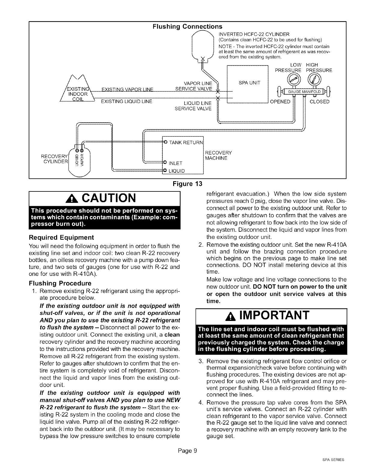
Flushing Connections
INVERTED HCFC-22 CYLINDER
/ (Contains clean HCFC-22 to be used for flushing)
/ NOTE - The inverted HCFC-22 cylinder must contain
i t at least the same amount of refrigerant as was recov-
"x.]__J ered from the existing system.
L f ---- PREsLuO "'#E SURE
VAPOR LIN_E_, I SPA UNIT (/_ ('_
SERVICE VALVE _ I ,_1 G_UGEMAN_p_
U_ _ qJ
tl o " ol111c os o
[L
RECOVERY
MACHINE
Figure 13
CAUTION
Required Equipment
You will need the following equipment in order to flush the
existing line set and indoor coil: two clean R-22 recovery
bottles, an oilless recovery machine with a pump down fea-
ture, and two sets of gauges (one for use with R-22 and
one for use with R-410A).
Flushing Procedure
1, Remove existing R-22 refrigerant using the appropri-
ate procedure below.
ff the existing outdoor unit is not equipped with
shut-off valves, or if the unit is not operational
AND you plan to use the existing R-22 refrigerant
to flush the system -- Disconnect all power to the ex-
isting outdoor unit. Connect the existing unit, a clean
recovery cylinder and the recovery machine according
to the instructions provided with the recovery machine.
Remove all R-22 refrigerant from the existing system.
Refer to gauges after shutdown to confirm that the en-
tire system is completely void of refrigerant. Discon-
nect the liquid and vapor lines from the existing out-
door unit,
If the existing outdoor unit is equipped with
manual shut-off valves AND you plan to use NEW
R-22 refrigerant to flush the system -- Start the ex-
isting R-22 system in the cooling mode and close the
liquid line valve. Pump all of the existing R-22 refriger-
ant back into the outdoor unit, (It may be necessary to
bypass the low pressure switches to ensure complete
,
refrigerant evacuation,) When the low side system
pressures reach 0 psig, close the vapor line valve. Dis-
connect all power to the existing outdoor unit, Refer to
gauges after shutdown to confirm that the valves are
not allowing refrigerant to flow back into the low side of
the system. Disconnect the liquid and vapor lines from
the existing outdoor unit,
Remove the existing outdoor unit, Set the new R-410A
unit and follow the brazing connection procedure
which begins on the previous page to make line set
connections, DO NOT install metering device at this
time.
Make low voltage and line voltage connections to the
new outdoor unit. DO NOT turn on power to the unit
or open the outdoor unit service valves at this
time.
AIMPORTANT
3. Remove the existing refrigerant flow control orifice or
thermal expansion/check valve before continuing with
flushing procedures. The existing devices are not ap-
proved for use with R-410A refrigerant and may pre-
vent proper flushing, Use a field-provided fitting to re-
connect the lines.
4. Remove the pressure tap valve cores from the SPA
unit's service valves, Connect an R-22 cylinder with
clean refrigerant to the vapor service valve. Connect
the R-22 gauge set to the liquid line valve and connect
a recovery machine with an empty recovery tank to the
gauge set,
Page 9
SPA SERIES
5, Set the recovery machine for liquid recovery and start
the recovery machine. Open the gauge set valves to
allow the recovery machine to pull a vacuum on the ex-
isting system line set and indoor coil,
6. Invert the cylinder of clean R-22 and open its valve to
allow liquid refrigerant to flow into the system through
the vapor line valve. Allow the refrigerant to pass from
the cylinder and through the line set and the indoor coil
before it enters the recovery machine,
7, After all of the liquid refrigerant has been recovered,
switch the recovery machine to vapor recovery so that
all of the R-22 vapor is recovered,
NOTE -A single system flush should remove all of the
mineral oil from the existing refrigerant lines and in-
door coil, A second flushing may be done (using clean
refrigerant) if insufficient amounts of mineral oil were
removed during the first flush, Each time the system
is flushed, you must allow the recovery machine
to pull a vacuum on the system at the end of the
procedure.
8. Close the valve on the inverted R-22 drum and the
gauge set valves. Pump the remaining refrigerant out
of the recovery machine and turn the machine off,
9, Use nitrogen to break the vacuum on the refrigerant
lines and indoor coil before removing the recovery ma-
chine, gauges and R-22 refrigerant drum, Reinstall
pressure tap valve cores into SPA service valves,
10, Install the provided check/expansion valve (approved
for use with R-410A refrigerant) in the liquid line at the
indoor coil,
AIMPORTANT
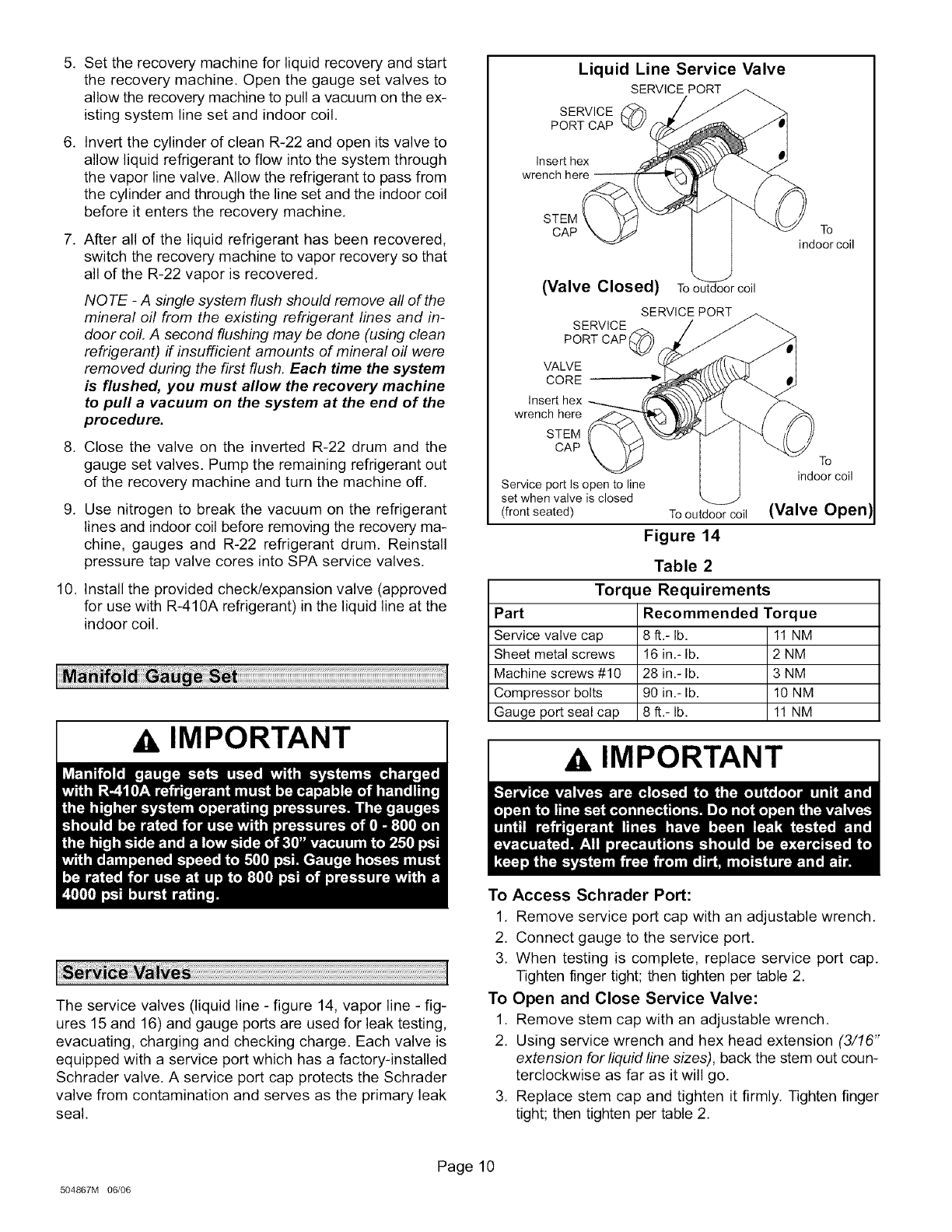
Liquid Line Service Valve
SERVICE PORT
SERVICE
PORT CAP
Insert hex
STEM
CAP To
indoor coil
(Valve Closed) To outdoor coil
SERVICE PORT
SERVICE
PORT CAP
VALVE
CORE
wrench here
STEM
CAP
To
indoor coil
Service port Is open to line
set when valve is closed
(front seated) To outdoor coil (Valve Open)
Figure 14
Table 2
Torque Requirements
Part Recommended Torque
Service valve cap 8 ft.- lb. 11NM
Sheet metal screws 16 in.- lb. 2 NM
Machine screws #10 28 in.- lb. 3 NM
Compressor bolts 90 in.- lb. 10 NM
Gauge port seal cap 8 ft.- lb. 11NM
AIMPORTANT
The service valves (liquid line - figure 14, vapor line - fig-
ures 15 and 16) and gauge ports are used for leak testing,
evacuating, charging and checking charge. Each valve is
equipped with a service port which has a factory-installed
Schrader valve. A service port cap protects the Schrader
valve from contamination and serves as the primary leak
seal.
To Access Schrader Port:
1, Remove service port cap with an adjustable wrench,
2. Connect gauge to the service port.
3, When testing is complete, replace service port cap,
Tighten finger tight; then tighten per table 2,
To Open and Close Service Valve:
1. Remove stem cap with an adjustable wrench.
2, Using service wrench and hex head extension (3/16"
extension for liquid line sizes), back the stem out coun-
terclockwise as far as it will go.
3, Replace stem cap and tighten it firmly, Tighten finger
tight; then tighten per table 2,
504867M 06/06
Page 10
WARNING
To Close Service Valve:
1. Remove stem cap with an adjustable wrench,
2. Using service wrench and hex head extension (3/16"
extension for fiquid line sizes), turn stem clockwise to
seat valve, Tighten it firmly.
3, Replace stem cap, Tighten finger tight; then tighten per
table 2,
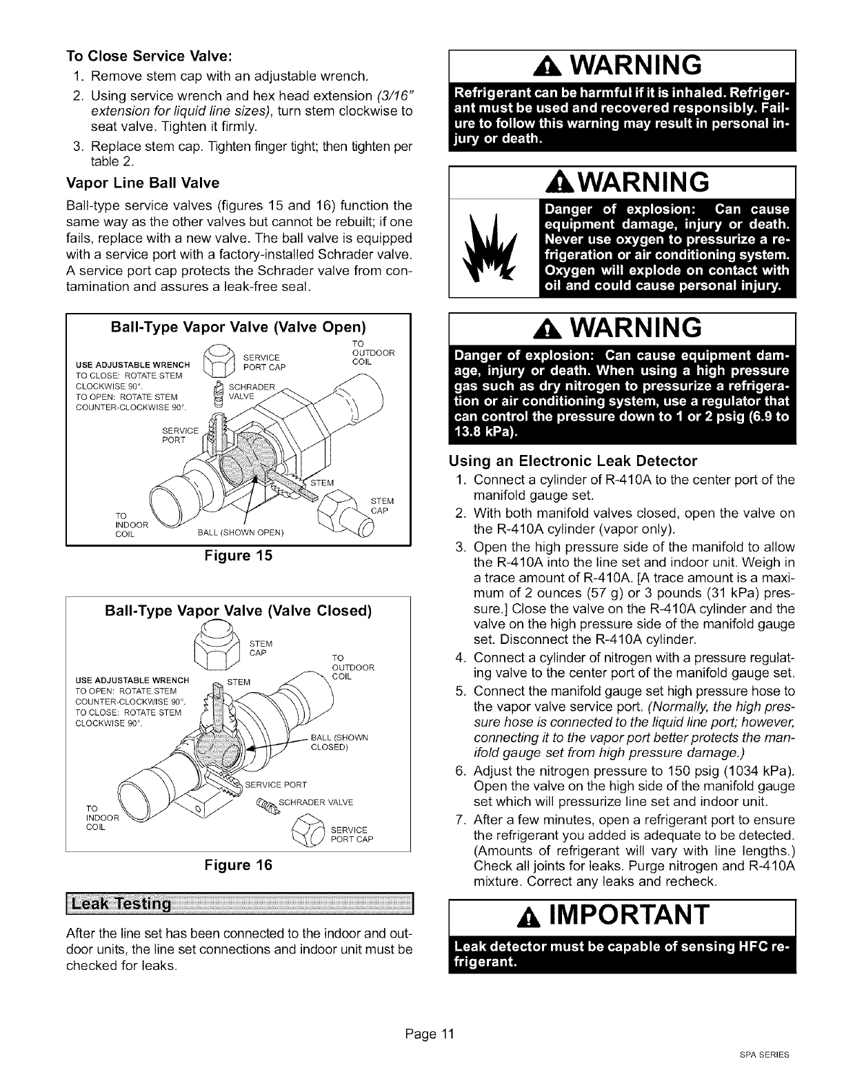
Vapor Line Ball Valve
Ball-type service valves (figures 15 and 16) function the
same way as the other valves but cannot be rebuilt; if one
fails, replace with a new valve. The ball valve is equipped
with a service port with a factory-installed Schrader valve.
A service port cap protects the Schrader valve from con-
tamination and assures a leak-free seal.
Bali-Type Vapor Valve (Valve Open)
TO
OUTDOOR
SERVICE COIL
USE ADJUSTABLE WRENCH PORT CAP
TO CLOSE: ROTATE STEM
CLOCKWISE 90°. SCHRADER
TO OPEN: ROTATE STEM
COUNTER-CLOCKWISE 90 °.
SERVICE
PORT
STEM
TO
INDOOR
COIL BALL (SHOWN OPEN)
Figure 15
USE ADJUSTABLE WRENCH
TO OPEN: ROTATE STEM
COUNTER-CLOCKWISE 90°.
TO CLOSE: ROTATE STEM
CLOCKWISE 90 °. _
,%o
COIL
Bali-Type Vapor Valve (Valve Closed)
STEMCAP TO
OUTDOOR
STEM COIL
!
s owN
_ S_ERVICE PORT
_SCHRADER VALVE
SERVICE
PORT CAP
Figure 16
After the line set has been connected to the indoor and out-
door units, the line set connections and indoor unit must be
checked for leaks.
WARNING
WARNING
Using an Electronic Leak Detector
1. Connect a cylinder of R-410A to the center port of the
manifold gauge set,
2. With both manifold valves closed, open the valve on
the R-410A cylinder (vapor only),
3. Open the high pressure side of the manifold to allow
the R-410A into the line set and indoor unit, Weigh in
a trace amount of R-410A, [A trace amount is a maxi-
mum of 2 ounces (57 g) or 3 pounds (31 kPa) pres-
sure,] Close the valve on the R-410A cylinder and the
valve on the high pressure side of the manifold gauge
set, Disconnect the R-410A cylinder,
4. Connect a cylinder of nitrogen with a pressure regulat-
ing valve to the center port of the manifold gauge set,
5. Connect the manifold gauge set high pressure hose to
the vapor valve service port. (Normally, the high pres-
sure hose is connected to the liquid line port; however,
connecting #to the vapor port better protects the man-
ifold gauge set from high pressure damage,)
6. Adjust the nitrogen pressure to 150 psig (1034 kPa),
Open the valve on the high side of the manifold gauge
set which will pressurize line set and indoor unit.
7. After a few minutes, open a refrigerant port to ensure
the refrigerant you added is adequate to be detected.
(Amounts of refrigerant will vary with line lengths.)
Check all joints for leaks, Purge nitrogen and R-410A
mixture. Correct any leaks and recheck.
AIMPORTANT
Page 11
SPA SERIES
Evacuating the system of noncondensables is critical for
proper operation of the unit. Noncondensables are defined
as any gas that will not condense under temperatures and
pressures present during operation of an air conditioning
system. Noncondensables and water vapor combine with
refrigerant to produce substances that corrode copper pip-
ing and compressor parts.
AIMPORTANT
1. Connect the manifold gauge set to the service valve
ports as follows:
• low pressure gauge to vapor line service valve
• high pressure gauge to liquid line service valve
2. Connect micron gauge.
3. Connect the vacuum pump (with vacuum gauge) to
the center port of the manifold gauge set.
4. Open both manifold valves and start vacuum pump.
5. Evacuate the line set and indoor unit to an absolute
pressure of 23,000 microns (29,01 inches of mercu-
ry). During the early stages of evacuation, it is desir-
able to close the manifold gauge valve at least once to
determine if there is a rapid rise in absolute pressure,
A rapid rise in pressure indicates a relatively large
leak. If this occurs, repeat the leak testing procedure.
NOTE - "Absolute pressure" means the total actual
pressure within a given volume or system, above the
absolute zero of pressure. Absolute pressure in a vac-
uum is equal to atmospheric pressure minus vacuum
pressure.
6. When the absolute pressure reaches 23,000 microns
(29.01 inches of mercury), close the manifold gauge
valves, turn off the vacuum pump and disconnect the
manifold gauge center port hose from vacuum pump.
Attach the manifold center port hose to a nitrogen cyl-
inder with pressure regulator set to 150 psig (1034
kPa) and purge the hose. Open the manifold gauge
valves to break the vacuum in the line set and indoor
unit. Close the manifold gauge valves.
WARNING I
7. Shut off the nitrogen cylinder and remove the manifold
gauge hose from the cylinder. Open the manifold
.
.
gauge valves to release the nitrogen from the line set
and indoor unit.
Reconnect the manifold gauge to the vacuum pump,
turn the pump on, and continue to evacuate the line set
and indoor unit until the absolute pressure does not
rise above 500 microns (29.9 inches of mercury) within
a 20-minute period after shutting off the vacuum pump
and closing the manifold gauge valves.
When the absolute pressure requirement above has
been met, disconnect the manifold hose from the vac-
uum pump and connect it to an upright cylinder of
R-410A refrigerant. Open the manifold gauge valves
to break the vacuum from 1 to 2 psig positive pressure
in the line set and indoor unit. Close manifold gauge
valves and shut off the R-410A cylinder and remove
the manifold gauge set.
IMPORTANT
1, Rotate fan to check for frozen bearings or binding.
2. Inspect all factory- and field-installed wiring for loose
connections.
3. After evacuation is complete, open the liquid line and
vapor line service valves (ccw) to release refrigerant
charge (contained in outdoor unit) into the system.
4. Replace stem caps and secure finger tight, then tight-
en an additional (1/6) one-sixth of a turn,
5. Check voltage supply at the disconnect switch. The
voltage must be within the range listed on the unit
nameplate. If not, do not start the equipment until the
power company has been consulted and the voltage
condition has been corrected.
6. Set the thermostat for a cooling demand, turn on pow-
er to indoor blower unit and close the outdoor unit dis-
connect to start the unit,
7, Recheck voltage while the unit is running. Power must
be within range shown on the nameplate,
Three-Phase Compressor Rotation
Three-phase scroll compressors must be phased sequen-
tially to ensure correct compressor rotation and operation.
At compressor start-up, a rise in discharge and drop in va-
por pressures indicate proper compressor phasing and op-
eration. If discharge and vapors pressures do not perform
normally, follow these steps to correctly phase in the unit:
1. Disconnect power to the unit.
2. Reverse any two field power leads to the unit.
3. Reapply power to the unit.
Discharge and vapor pressures should operate at their
normal start-up ranges.
504867M 06/06
Page 12
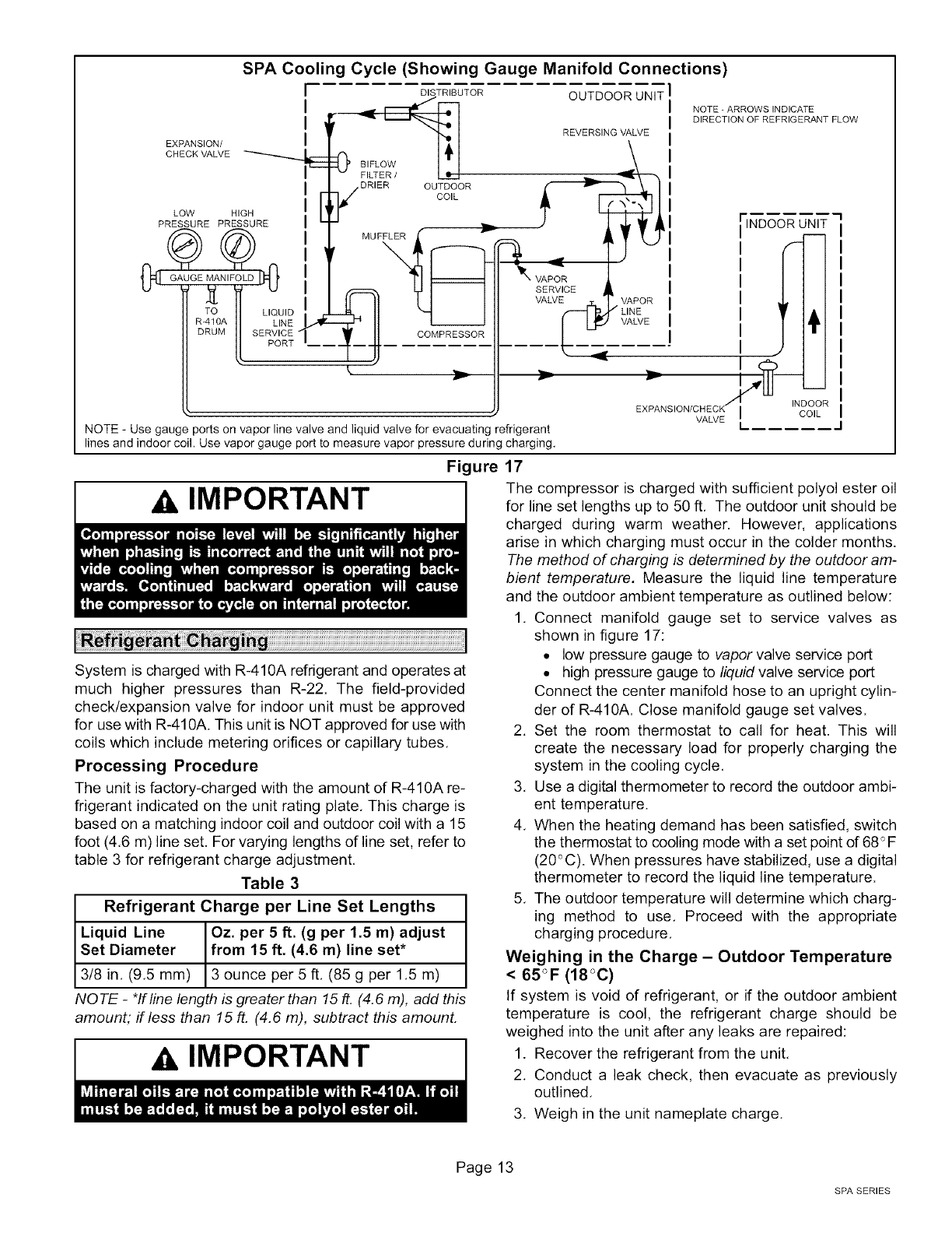
SPA Cooling Cycle (Showing Gauge Manifold Connections)
r
i
i
EXPANSION/ I
CHECK VALVE
LOW HIGH
PRESSURE PRESSURE
J
DISTRIBUTOR
BIFLOW
DRIER OUTDOOR
dCOIL
M U FLL__"-
COMPRESSOR
t
%
X
OUTDOOR UNIT
NOTE _ARROWS INDICATE
DIRECTION OF REFRIGERANT FLOW
REVERSING VALVE
_! INDOOR_L]
I III
NOTE - Use gauge ports on vapor line valve and liquid valve for evacuating refrigerant
lines and indoor coil. Use vapor gauge port to measure vapor pressure during charging,
Figure 17
AIMPORTANT
System is charged with R-410A refrigerant and operates at
much higher pressures than R-22. The field-provided
check/expansion valve for indoor unit must be approved
for use with R-410A. This unit is NOT approved for use with
coils which include metering orifices or capillary tubes,
Processing Procedure
The unit is factory-charged with the amount of R-410A re-
frigerant indicated on the unit rating plate, This charge is
based on a matching indoor coil and outdoor coil with a 15
foot (4,6 m) line set. For varying lengths of line set, refer to
table 3 for refrigerant charge adjustment,
Table 3
Refrigerant Charge per Line Set Lengths
Liquid Line Oz. per 5 ft. (g per 1.5 m) adjust
Set Diameter from 15 ft. (4.6 m) line set*
3/8 in, (9,5 mm) 3 ounce per 5 ft, (85 g per1,5 m)
NOTE - *If line length is greater than 15 ft. (4.6 m), add this
amount; if less than 15 ft. (4.6 m), subtract this amount.
AIMPORTANT
The compressor is charged with sufficient polyol ester oil
for line set lengths up to 50 ft, The outdoor unit should be
charged during warm weather. However, applications
arise in which charging must occur in the colder months.
The method of charging is determined by the outdoor am-
bient temperature. Measure the liquid line temperature
and the outdoor ambient temperature as outlined below:
1. Connect manifold gauge set to service valves as
shown in figure 17:
• low pressure gauge to vapor valve service port
• high pressure gauge to liquid valve service port
Connect the center manifold hose to an upright cylin-
der of R-410A. Close manifold gauge set valves.
2. Set the room thermostat to call for heat. This will
create the necessary load for properly charging the
system in the cooling cycle,
3. Use a digital thermometer to record the outdoor ambi-
ent temperature.
4. When the heating demand has been satisfied, switch
the thermostat to cooling mode with a set point of 68_F
(20_%). When pressures have stabilized, use a digital
thermometer to record the liquid line temperature.
5. The outdoor temperature will determine which charg-
ing method to use, Proceed with the appropriate
charging procedure,
Weighing in the Charge - Outdoor Temperature
< 65°F (18°0)
If system is void of refrigerant, or if the outdoor ambient
temperature is cool, the refrigerant charge should be
weighed into the unit after any leaks are repaired:
1. Recover the refrigerant from the unit,
2. Conduct a leak check, then evacuate as previously
outlined,
3. Weigh in the unit nameplate charge.
Page 13
SPA SERIES
If weighing facilities are not available or if you are charging
the unit during warm weather, follow one of the other pro-
cedures outlined below.
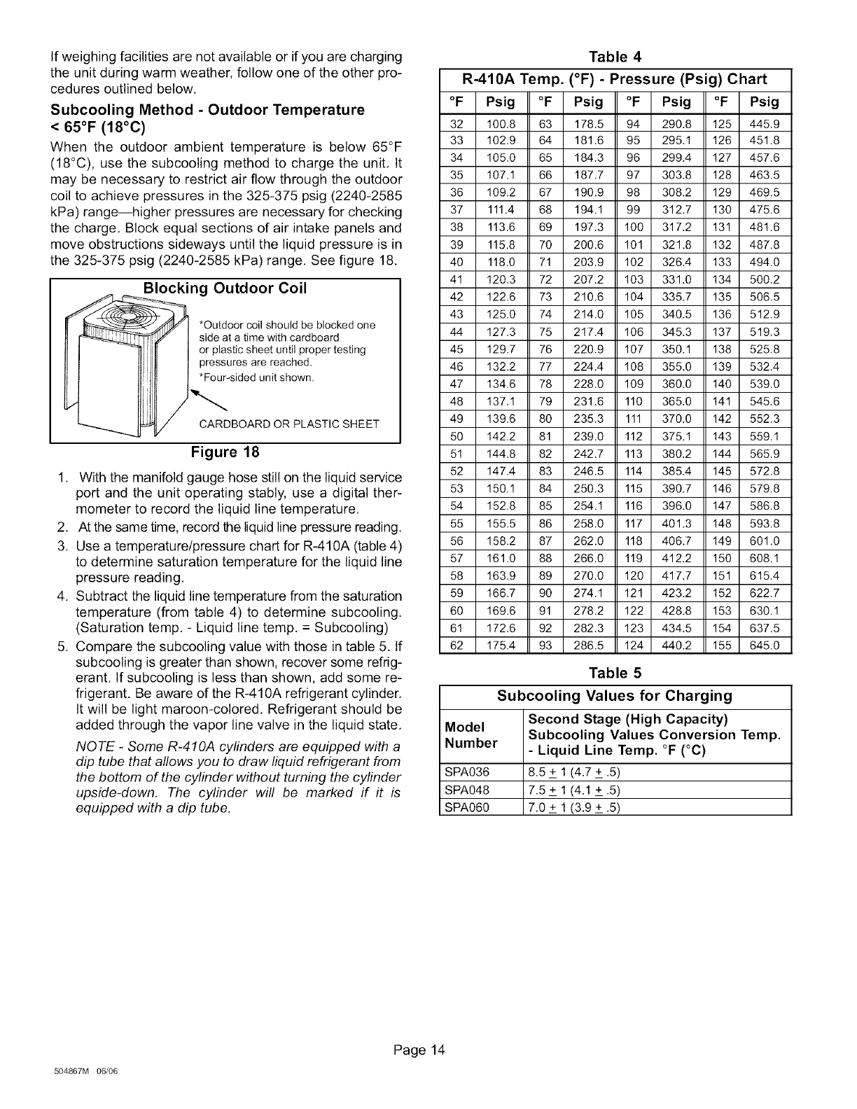
Subcooling Method - Outdoor Temperature
< 65°F (18°C)
When the outdoor ambient temperature is below 65°F
(18°C), use the subcooling method to charge the unit. It
may be necessary to restrict air flow through the outdoor
coil to achieve pressures in the 325-375 psig (2240-2585
kPa) range--higher pressures are necessary for checking
the charge. Block equal sections of air intake panels and
move obstructions sideways until the liquid pressure is in
the 325-375 psig (2240-2585 kPa) range. See figure 18.
Blocking Outdoor Coil
__ *Outdoor coil should be blocked one
_Y I side at a time with cardboard
If [I I or plastic sheet until proper testing
]),11 I .PrF:Su_.U:ied:d r:nri___hoevdn''
)-...
CARDBOARD OR PLASTIC SHEET
Figure 18
1. With the manifold gauge hose still on the liquid service
port and the unit operating stably, use a digital ther-
mometer to record the liquid line temperature.
2. At the same time, record the liquid line pressure reading.
3. Use a temperature/pressure chart for R-410A (table 4)
to determine saturation temperature for the liquid line
pressure reading.
4. Subtract the liquid line temperature from the saturation
temperature (from table 4) to determine subcooling.
(Saturation temp. - Liquid line temp. = Subcooling)
5. Compare the subcooling value with those in table 5. If
subcooling is greater than shown, recover some refrig-
erant. If subcooling is less than shown, add some re-
frigerant. Be aware of the R-410A refrigerant cylinder.
It will be light maroon-colored. Refrigerant should be
added through the vapor line valve in the liquid state.
NOTE -Some R-410A cylinders are equipped with a
dip tube that allows you to draw liquid refrigerant from
the bottom of the cylinder without turning the cylinder
upside-down. The cylinder will be marked if it is
equipped with a dip tube.
Table 4
R-410A Temp. (°F) - Pressure (Psig) Chart
°F Psig °F Psig °F Psig °F Psig
32 100.8 63 178.5 94 290.8 125 445.9
33 102.9 64 181.6 95 295.1 126 451.8
34 105.0 65 184.3 96 299.4 127 457.6
35 107.1 66 187.7 97 303.8 128 463.5
36 109.2 67 190.9 98 308.2 129 469.5
37 111.4 68 194.1 99 312.7 130 475.6
38 113.6 69 197.3 100 317.2 131 481.6
39 115.8 70 200.6 101 321.8 132 487.8
40 118.0 71 203.9 102 326.4 133 494.0
41 120.3 72 207.2 103 331.0 134 500.2
42 122.6 73 210.6 104 335.7 135 506.5
43 125.0 74 214.0 105 340.5 136 512.9
44 127.3 75 217.4 106 345.3 137 519.3
45 129.7 76 220.9 107 350.1 138 525.8
46 132.2 77 224.4 108 355.0 139 532.4
47 134.6 78 228.0 109 360.0 140 539.0
48 137.1 79 231.6 110 365.0 141 545.6
49 139.6 80 235.3 111 370.0 142 552.3
50 142.2 81 239.0 112 375.1 143 559.1
51 144.8 82 242.7 113 380.2 144 565.9
52 147.4 83 246.5 114 385.4 145 572.8
53 150.1 84 250.3 115 390.7 146 579.8
54 152.8 85 254.1 116 396.0 147 586.8
55 155.5 86 258.0 117 401.3 148 593.8
56 158.2 87 262.0 118 406.7 149 601.0
57 161.0 88 266.0 119 412.2 150 608.1
58 163.9 89 270.0 120 417.7 151 615.4
59 166.7 90 274.1 121 423.2 152 622.7
60 169.6 91 278.2 122 428.8 153 630.1
61 172.6 92 282.3 123 434.5 154 637.5
62 175.4 93 286.5 124 440.2 155 645.0
Table 5
Subcooling Values for Charging
Model
Number
SPA036
SPA048
SPA060
Second Stage (High Capacity)
Subcooling Values Conversion
- Liquid Line Temp. °F (°C)
8.5 + 1 (4.7 + .5)
7.5 + 1 (4.1 + .5)
7.0 + 1 (3.9 + .5)
Temp.
504867M 06/06
Page 14
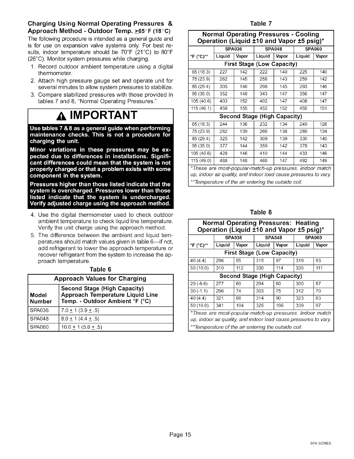
Charging Using Normal Operating Pressures &
Approach Method - Outdoor Temp. >65<_F(18°C)
The following procedure is intended as a general guide and
is for use on expansion valve systems only. For best re-
sults, indoor temperature should be 70°F (21°C) to 80°F
(26°C). Monitor system pressures while charging.
1. Record outdoor ambient temperature using a digital
thermometer.
2. Attach high pressure gauge set and operate unit for
several minutes to allow system pressures to stabilize.
3. Compare stabilized pressures with those provided in
tables 7 and 8, "Normal Operating Pressures."
IMPORTANT
Table 7
Normal Operating Pressures - Cooling
Operation (Liquid +10 and Vapor +5 psig)*
SPA036 SPA048 SPA060
°F (°C)** Liquid I Vapor Liquid I Vapor Liquid I Vapor
First Stage (Low Capacity)
65 (18.3) 227 142 222 140 225 140
75 (23.9) 262 145 258 143 259 142
85 (29.4) 305 146 298 145 293 146
95 (35.0) 352 148 343 147 356 147
105 (40.6) 403 152 402 147 408 147
115 (46.1) 458 155 452 152 455 151
Second Stage (High Capacity)
65 (18.3) 244 136 232 134 249 126
75 (23.9) 282 139 266 136 289 134
85 (29.4) 325 142 309 139 330 140
95 (35.0) 377 144 359 142 378 143
105 (40.6) 428 146 410 144 433 146
115 (49.0) 488 148 468 147 492 149
*These are most-popular-match-up pressures. Indoor match
up, indoor air quality, and indoor load cause pressures to vary.
**Temperature of the air entering the outside coil.
Table 8
Normal Operating Pressures: Heating
Operation (Liquid +10 and Vapor +5 psig)*
SPA036 SPA048 SPA060
°F (°C)** Liquid I Vapor Liquid Ivapor Liquid Ivapor
First Stage (Low Capacity)
40(4.4) 296 95 315 _4 319 _1
50 (10.0) 310 112 330 335
Second Stage (High Capacity)
20 (-6.6) 277 60 294 60 300 57
30 (-1.1) 296 74 303 75 312 70
40 (4.4) 321 88 314 90 323 83
50 (10.0) 341 104 325 106 339 97
*These are most-popular-match-up pressures. Indoor match
up, indoor air quality, and indoor load cause pressures to vary,
**Temperature of the air entering the outside coil.
4. Use the digital thermometer used to check outdoor
ambient temperature to check liquid line temperature.
Verify the unit charge using the approach method.
5. The difference between the ambient and liquid tem-
peratures should match values given in table 6--if not,
add refrigerant to lower the approach temperature or
recover refrigerant from the system to increase the ap-
proach temperature.
Table 6
Approach Values for Charging
Second Stage (High Capacity)
Model Approach Temperature Liquid Line
Number Temp. - Outdoor Ambient °F (°C)
SPA036 7.0 + 1 (3.9 + .5)
SPA048 8.0 + 1 (4.4 + .5)
SPA060 10.0 + 1 (5.6 + .5)
Page 15
SPA SERIES
Emergency Heat (Amber Light)
An emergency heat function is designed into some room
thermostats. This feature is applicable when isolation dthe
outdoor unit is required, or when auxiliary electric heat is
staged by outdoor thermostats. When the room thermostat is
placed in the emergency heat position, the outdoor unit con-
trol circuit is isolated from power and field-provided relays by-
pass the outdoor thermostats. An amber indicating light si-
multaneously comes on to remind the homeowner that he is
operating in the emergency heat mode.
Emergency heat is usually used during an outdoor unit
shutdown, but it should also be used following a power out-
age if power has been off for over an hour and the outdoor
temperature is below 50°F (10°C). System should be left in
the emergency heat mode at least six hours to allow the
crankcase heater sufficient time to prevent compressor
slugging.
Filter Brier
The unit is equipped with a large-capacity biflow filter drier
which keeps the system clean and dry. If replacement is
necessary, order another of like design and capacity. The
replacement filter drier must be suitable for use with
R-410A refrigerant.
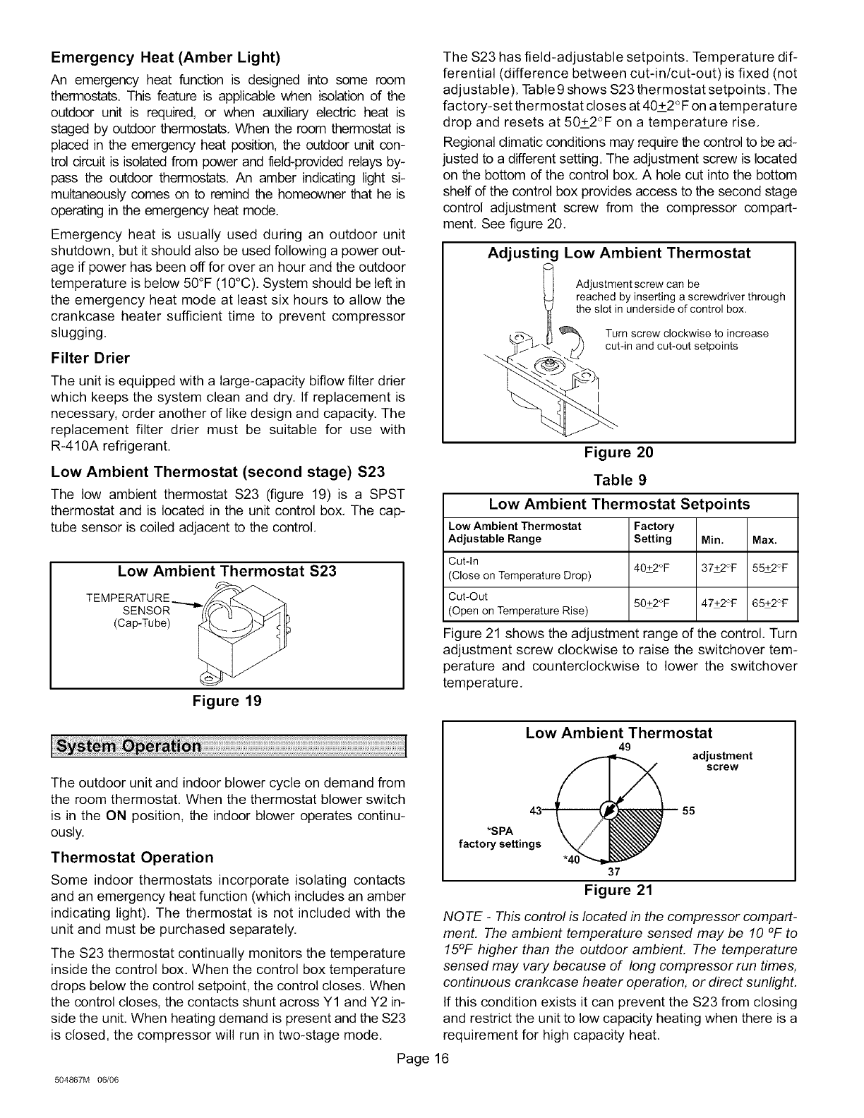
Low Ambient Thermostat (second stage) $23
The low ambient thermostat S23 (figure 19) is a SPST
thermostat and is located in the unit control box. The cap-
tube sensor is coiled adjacent to the control.
Low Ambient Thermostat $23
TEMPERATURE __
SENSOR
(Cap-Tube)
Figure 19
The S23 has field-adjustable setpoints. Temperature dif-
ferential (difference between cut-in/cut-out) is fixed (not
adjustable). Table 9 shows S23 thermostat setpoints. The
factory-set thermostat closes at 40+2°F on a temperature
drop and resets at 50+2°F on a temperature rise.
Regional climatic conditions may require the control to be ad-
justed to a different setting. The adjustment screw is located
on the bottom dthe control box. A hole cut into the bottom
shelf of the control box provides access to the second stage
control adjustment screw from the compressor compart-
ment. See figure 20.
Adjusting Low Ambient Thermostat
Adjustment screw can be
reached by inserting a screwdriver through
the slot in underside of control box.
Turn screw clockwise to increase
cut-in and cut-out setpoints
Figure 20
Table 9
Low Ambient Thermostat Setpoints
Low Ambient Thermostat Factory
Adjustable Range Setting Min. Max.
Cut-in 40+2°F 37+2°F 55+2°F
(Close on Temperature Drop)
Cut-Out 50+2°F 47+2°F 65+2°F
(Open on Temperature Rise)
Figure 21 shows the adjustment range of the control. Turn
adjustment screw clockwise to raise the switchover tem-
perature and counterclockwise to lower the switchover
temperature.
The outdoor unit and indoor blower cycle on demand from
the room thermostat. When the thermostat blower switch
is in the ON position, the indoor blower operates continu-
ously.
Thermostat Operation
Some indoor thermostats incorporate isolating contacts
and an emergency heat function (which includes an amber
indicating light). The thermostat is not included with the
unit and must be purchased separately.
The S23 thermostat continually monitors the temperature
inside the control box. When the control box temperature
drops below the control setpoint, the control closes. When
the control closes, the contacts shunt across Y1 and Y2 in-
side the unit. When heating demand is present and the S23
is closed, the compressor will run in two-stage mode.
Low Ambient Thermostat
49
4_ adjustment
screw
*SPA 43_ 55
factory settingsX
37
Figure 21
NOTE -This control is located in the compressor compart-
ment. The ambient temperature sensed may be 10 °F to
15°F higher than the outdoor ambient. The temperature
sensed may vary because of long compressor run times,
continuous crankcase heater operation, or direct sunlight.
If this condition exists it can prevent the S23 from closing
and restrict the unit to low capacity heating when there is a
requirement for high capacity heat.
Page 16
504867M 06/06
Ambient Compensation Adjustments
In order to overcome this potential situation, there are two
possible adjustments:
• The factory setting of the S23 can be reset to a higher
temperature. This allows the controller to compensate
for the ambient temperature differences. (Control set-
ting 65°K compartment 65°F - outdoor ambient 55°F).
• Secondly, the capillary tube on the control can be
routed with the low voltage thermostat wires. Because
the capillary tube senses at its coldest point, tempera-
ture variation will be reduced between the control and
the outdoor ambient temperature. (Keep capillary tube
away from direct sunlight).
Single-Stage Heating Application
In single-stage heat applications, the low ambient thermo-
stat can be set to the highest setting. The system will oper-
ate in second-stage heating when the temperature drops
below 55+ 2°F, and returns to first-stage when the temper-
ature rises above 65 + 2°R The low-stage heating capacity
is approximates 70% of the high-stage heating capacity.
Discharge Temperature Thermostat
Units are equipped with a discharge temperature thermo-
stat that is located on the discharge line just below the muf-
fler. The switch shuts off the compressor when the dis-
charge line temperature rises above 250°F _+5 (121°C _+
-2,8) and resets at 200°F _+11 (93°C _+-6,1 ),
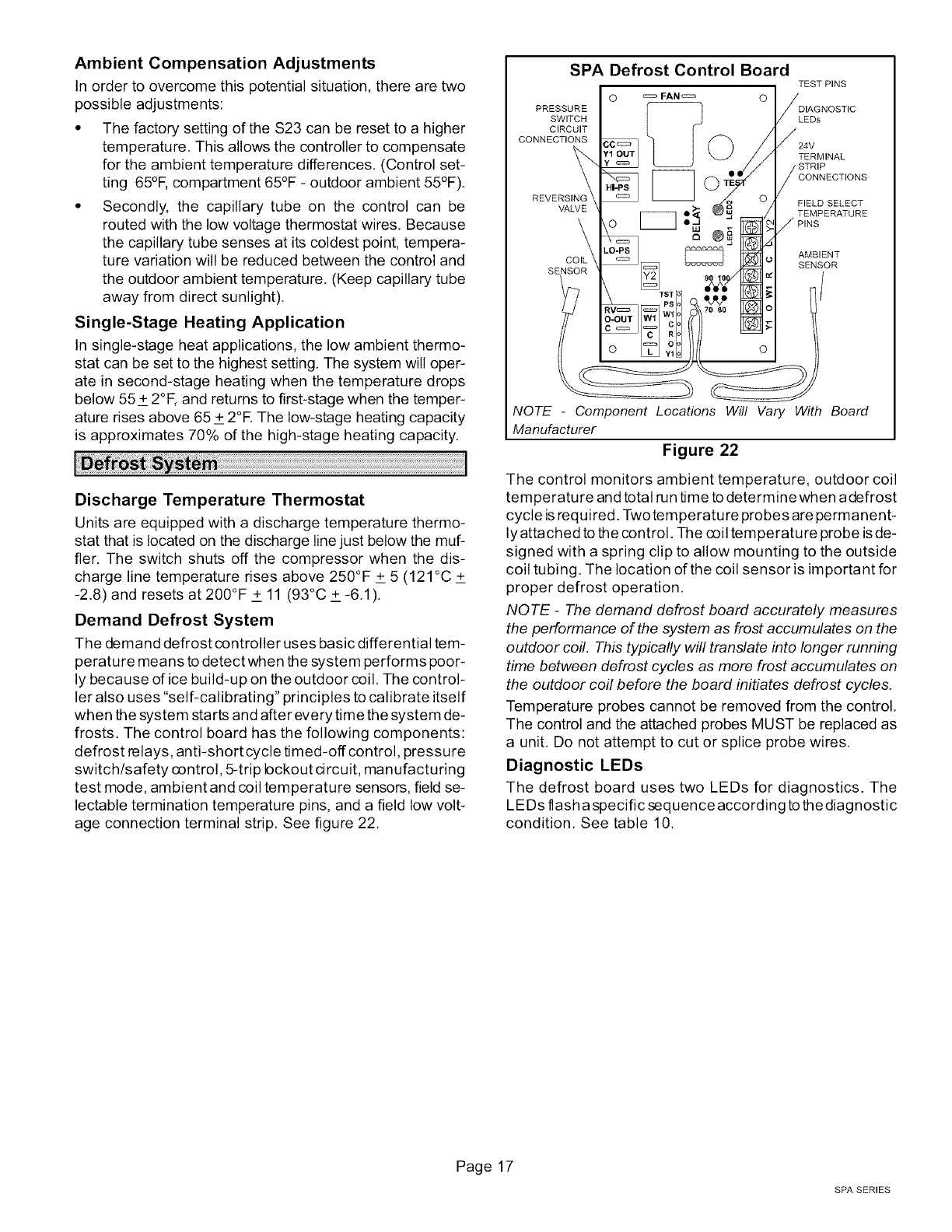
Demand Defrost System
The demand defrost controller uses basic differential tem-
perature means to detect when the system performs poor-
ly because of ice build-up on the outdoor coil. The control-
ler also uses "self-calibrating" principles to calibrate itself
when the system starts and after every time the system de-
frosts. The control board has the following components:
defrost relays, anti-short cycle timed-off control, pressure
switch/safety control, 5-trip bckout circuit, manufacturing
test mode, ambient and coil temperature sensors, field se-
lectable termination temperature pins, and a field low volt-
age connection terminal strip. See figure 22.
SPA Defrost Control Board
TEST PINS
O _ FAN _ O /
i,ssovi,i
CONNECTIONS ;6 c:=_ 24V
\ '_ _ .// .STR,P
\"CONNECT,ONS
REVERSING _ I I = 0
VALVE
\ \o II,d _lf_ /P,NS
\ LO.P8 _j AMBIENT
COIL _ _ _{J SENSOR
SENSOR 90 10 tz
O-OUT RC
l/ o
NOTE -Component Locations Will Vary With Board
Manufacturer
Figure 22
The control monitors ambient temperature, outdoor coil
temperature and total run time to determine when a defrost
cycle is required. Two temperature probes are permanent-
ly attached to the control. The coil temperature probe is de-
signed with a spring clip to allow mounting to the outside
coil tubing. The location of the coil sensor is important for
proper defrost operation.
NOTE -The demand defrost board accurately measures
the performance of the system as frost accumulates on the
outdoor coil. This typically will translate into longer running
time between defrost cycles as more frost accumulates on
the outdoor coil before the board initiates defrost cycles.
Temperature probes cannot be removed from the control.
The control and the attached probes MUST be replaced as
a unit. Do not attempt to cut or splice probe wires.
Diagnostic LEDs
The defrost board uses two LEDs for diagnostics. The
LEDs lasha specific sequenceaccording to thediagnostic
condition. See table 10.
Page 17
SPA SERIES
Low Pressure Switch (LO-PS)
The unit's automatic reset low pressure switch ($87) is fac-
tory-wired into the defrost board on the LO-PS terminals,
When the low pressure switch trips, the defrost board will
cycle off the compressor, and the strike counter in the
board will count one strike, ($87) is ignored under the fol-
lowing conditions:
• during the defrost cycle and 90 seconds after the ter-
mination of defrost
• when the average ambient sensor temperature is be-
low 15° F (-9°C)
• for 90 seconds following the start up of the compressor
• during "test" mode
High Pressure Switch (HI-PS)
The unit's automatic reset high pressure switch ($4) is fac-
tory-wired into the defrost board on the Ht-PS terminals.
When the high pressure switch trips, the defrost board will
cycle off the compressor, and the strike counter in the
board will count one strike.
Calibration of the board occurs after a defrost cycle to
ensure that there is no ice on the coil. During calibra-
tion, the temperature of both the coil and the ambient
sensor are measured to establish the temperature dif-
ferential which is required to allow a defrost cycle.
Before the start of each heating and cooling season, the
following service checks should be performed by a quali-
fied service technician,
•TURN OFF electrical power to the unit prior to unit
maintenance.
_WARNING
5-Strike Lockout Feature
• Internal control logic of the board counts the pressure
switch trips only while the Y1 (Input) line is active. If a
pressure switch opens and closes four times during a
Y1 (Input), the control logic resets the pressure switch
trip counter to zero at the end of the Y1 (Input). If the
pressure switch opens for a fifth time during the cur-
rent Y1 (Input), the control enters a lockout condition.
• The 5-strike pressure switch lockout condition can be
reset by cycling OFF the 24-volt power to the control
board or by shorting the TEST pins. All timer functions
(run times) will also be reset.
• If a pressure switch opens while the Y1 Out line is en-
gaged, a 5-minute short cycle will occur after the
switch closes.
Delay Mode
The defrost board has a field-selectable function to reduce
occasional sounds that may occur while the unit is cycling
in and out of the defrost mode. When a jumper is installed
on the DELAY pins, the compressor will be cycled off for 30
seconds going in and out of the defrost mode. Units are
shipped with jumper installed on DELAY pins.
NQTE -The 30 second off cycle is not functional when
jumpering the TEST pins.
Operational Description
The defrost control board has three operational modes:
1. Normal Mode - The demand defrost board monitors
the O line, to determine the system operating mode
(heat/cool), outdoor ambient temperature, coil tem-
perature (outdoor coil) and compressor run time to de-
termine when a defrost cycle is required.
2. Defrost Mode - See table 10 for defrost mode and de-
mand defrost operation.
3. Calibration Mode - The board is considered uncali-
brated when power is applied to the board, after cool
mode operation, or if the coil temperature exceeds the
termination temperature when it is in heat mode.
• Inspect and clean the outdoor and indoor coils. The
outdoor coil may be flushed with a water hose.
NQ TE -It may be necessary to flush the outdoor coil
more frequently if it is exposed to substances which
are corrosive or which block airflow across the coil
(e.g., pet urine, cottonwood seeds, etc.).
• Visually inspect refrigerant lines and coils for leaks.
• Check wiring for loose connections.
• Check voltage at indoor and outdoor units during op-
eration.
• Check the amp-draw at the outdoor fan motor, com-
pressor, and indoor blower motor. Compare readings
with values given on unit nameplate.
• Clean or replace indoor unit filters.
• Check refrigerant charge and system pressures.
• Check condensate drain line for free and unobstructed
flow; clean if necessary.
Outdoor unit fan motor is prelubricated and sealed. No
further lubrication is needed.
NQ TE -If owner reports insufficient cooling, the unit
should be gauged and refrigerant charge checked.
(See Refrigerant Charging on Page 13.)
Refer to the Engineering Handbook for optional accesso-
ries that may apply to this unit, e.g.:
• Loss of Charge Kit
• Compressor Monitor
• Hail Guards
• Mounting Bases
• Timed Off Control
• Stand-off Kit
• Sound Cover
• Low Ambient Kit
• Monitor Kit
Page 18
504867M 06/06
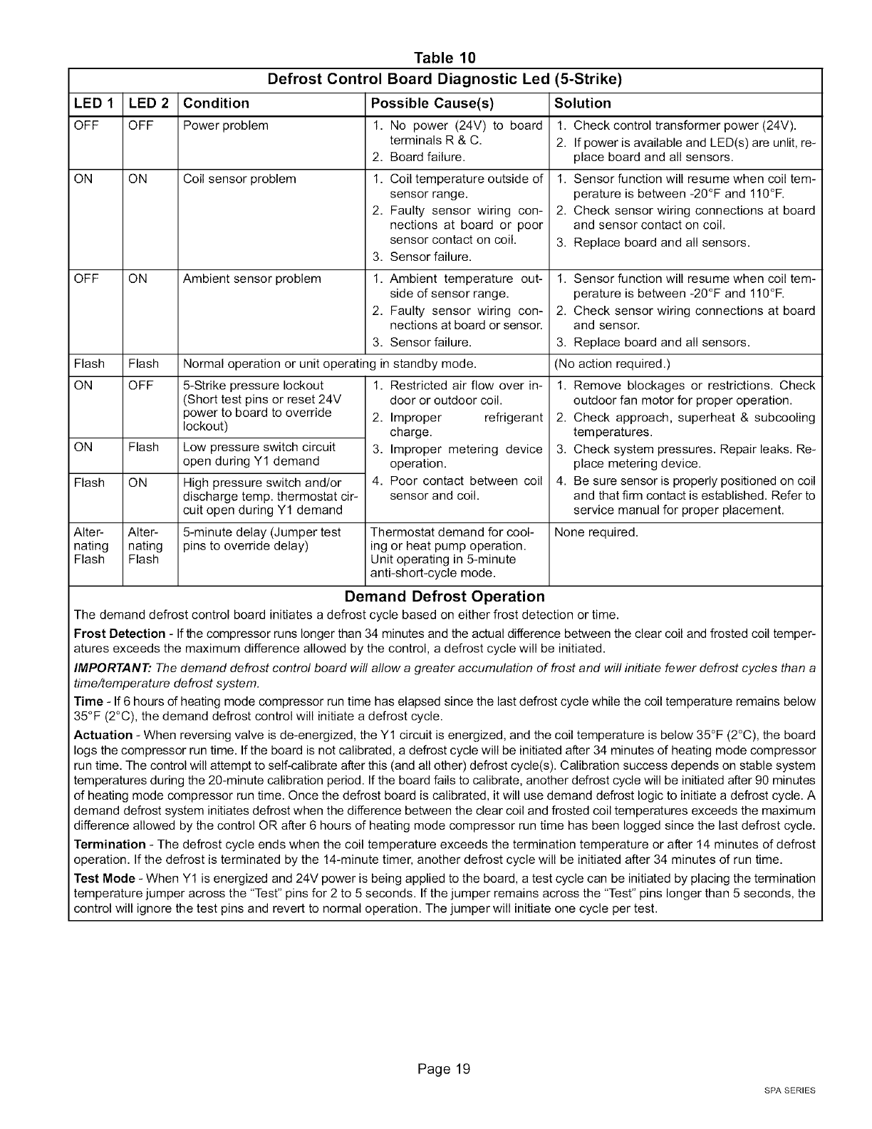
Table 10
Defrost Control Board Diagnostic Led
LED 1 LED 2 Condition Possible Cause(s)
OFF OFF Power problem 1. No power (24V) to board
terminals R & C.
2. Board failure.
ON ON Coil sensor problem 1. Coil temperature outside of
sensor range.
2. Faulty sensor wiring con-
nections at board or poor
sensor contact on coil.
3. Sensor failure.
OFF ON Ambient sensor problem 1. Ambient temperature out-
side of sensor range.
2. Faulty sensor wiring con-
nections at board or sensor.
3. Sensor failure.
Flash Flash Normal operation or unit operating in standby mode.
ON OFF 5-Strike pressure lockout
(Short test pins or reset 24V
power to board to override
lockout)
ON Flash Low pressure switch circuit
open during Y1 demand
Flash ON High pressure switch and/or
discharge temp. thermostat cir-
cuit open during Y1 demand
Alter- Alter-
nating nating
Flash Flash
5-minute delay (Jumper test
pins to override delay)
1. Restricted air flow over in-
door or outdoor coil.
2. Improper refrigerant
charge.
3. Improper metering device
operation.
4. Poor contact between coil
sensor and coil.
Thermostat demand for cool-
ing or heat pump operation.
Unit operating in 5-minute
anti-short-cycle mode.
(5-Strike)
Solution
1. Check control transformer power (24V).
2. If power is available and LED(s) are unlit, re-
place board and all sensors.
1. Sensor function will resume when coil tem-
perature is between -20°F and 110°F.
2. Check sensor wiring connections at board
and sensor contact on coil.
3. Replace board and all sensors.
1. Sensor function will resume when coil tem-
perature is between -20°F and 110°F.
2. Check sensor wiring connections at board
and sensor.
3. Replace board and all sensors.
(No action required.)
1. Remove blockages or restrictions. Check
outdoor fan motor for proper operation.
2. Check approach, superheat & subcooling
ternperatures.
3. Check system pressures. Repair leaks. Re-
place metering device.
4. Be sure sensor is properly positioned on coil
and that firm contact is established. Refer to
service manual for proper placement.
None required.
Demand Defrost Operation
The demand defrost control board initiates a defrost cycle based on either frost detection or time.
Frost Detection - If the compressor runs longer than 34 minutes and the actual difference between the clear coil and frosted coil temper-
atures exceeds the maximum difference allowed by the control, a defrost cycle will be initiated.
IMPORTANT." The demand defrost control board will aflow a greater accumulation of frost and will initiate fewer defrost cycles than a
time/temperature defrost system.
Time - If6 hours dheating mode compressor run time has elapsed since the last defrost cycle while the coil temperature remains below
35°F (2°C), the demand defrost control will initiate a defrost cycle.
Actuation - When reversing valve is de-energized, the Y1 circuit is energized, and the coil temperature is below 35°F (2°C), the board
logs the compressor run time. If the board is not calibrated, a defrost cycle will be initiated after 34 minutes of heating mode compressor
run time. The control will attempt to self-calibrate after this (and all other) defrost cycle(s). Calibration success depends on stable system
temperatures during the 20-minute calibration period. If the board fails to calibrate, another defrost cycle will be initiated after 90 minutes
of heating mode compressor run time. Once the defrost board is calibrated, it will use demand defrost logic to initiate a defrost cycle. A
demand defrost system initiates defrost when the difference between the clear coil and frosted coil temperatures exceeds the maximum
difference allowed by the control OR after 6 hours of heating mode compressor run time has been logged since the last defrost cycle.
Termination - The defrost cycle ends when the coil temperature exceeds the termination temperature or after 14 minutes of defrost
operation. If the defrost is terminated by the 14-minute timer, another defrost cycle will be initiated after 34 minutes of run time.
Test Mode - When Y1 is energized and 24V power is being applied to the board, a test cycle can be initiated by placing the termination
temperature jumper across the "Test" pins for 2 to 5 seconds. If the jumper remains across the "Test" pins longer than 5 seconds, the
control will ignore the test pins and revert to normal operation. The jumper will initiate one cycle per test.
Page 19
SPA SERIES
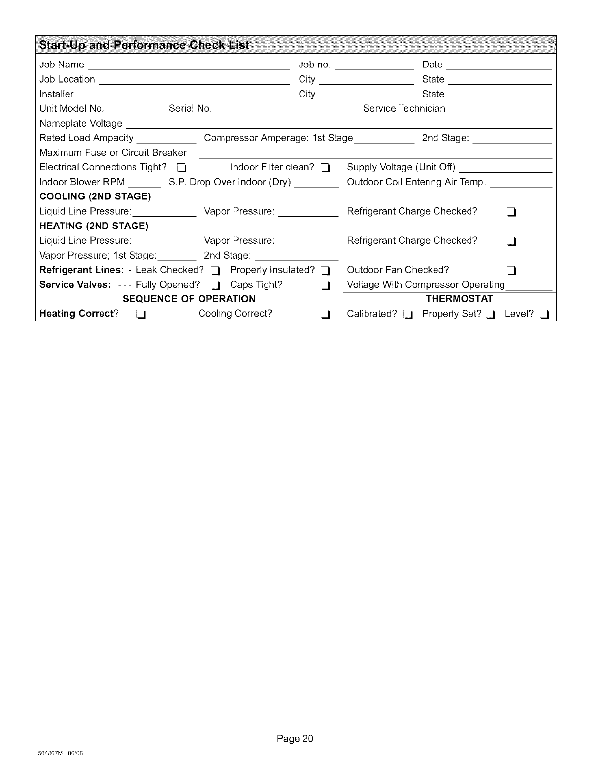
Job Name
Job Location
Installer
Unit Model No,
Nameplate Voltage
Rated Load Ampacity
Maximum Fuse or Circuit Breaker
Electrical Connections Tight?
Serial No.
Job no.
City
City
Compressor Amperage: 1st Stage
Indoor Filter clean?
Indoor Blower RPM
COOLING (2ND STAGE)
Liquid Line Pressure:
HEATING (2ND STAGE)
Liquid Line Pressure: Vapor Pressure:
Vapor Pressure; 1st Stage: 2nd Stage:
Refrigerant Lines: - Leak Checked? _ Properly Insulated?
Service Valves: --- Fully Opened? _ Caps Tight?
SEQUENCE OF OPERATION
Heating Correct? _ Cooling Correct?
S.P. Drop Over Indoor (Dry)
Vapor Pressure:
Date
State
State
Service Technician
2nd Stage:
Supply Voltage (Unit Off)
Outdoor Coil Entering Air Temp.
Refrigerant Charge Checked?
Refrigerant Charge Checked?
Outdoor Fan Checked?
Voltage With Compressor Operating
THERMOSTAT
Calibrated? Properly Set? _ Level?
504867M 06/06
Page 20
