LENNOX Package Units(both Units Combined) Manual L0806665
User Manual: LENNOX LENNOX Package Units(both units combined) Manual LENNOX Package Units(both units combined) Owner's Manual, LENNOX Package Units(both units combined) installation guides
Open the PDF directly: View PDF ![]() .
.
Page Count: 17
,t,: 2005 Lennox industries inc.
Dallas, Texas, USA
INSTALLATION
INSTRUCTIONS
13GCSX SERIES UNITS
RETAIN THESE INSTRUCTIONS
FOR FUTURE REFERENCE
c( )0s
GAS PACKAGED UNITS (2-5 TONS) F_ Technical
505,057M _L.LLPublications
(38152A067)
08/05 Lithe U.S.A.
Supersedes 06/05
Unit Dimensions ............................... 2
Parts Arrangement ............................. 3
Shipping & Packing List ......................... 3
General ....................................... 3
Safety Information .............................. 3
Location Selection .............................. 4
Rigging & Setting Unit .......................... 5
Clearances .................................... 5
Installing Vent Hood ............................ 6
Existing Common Vent Systems .................. 6
Condensate Drain .............................. 7
Filters ......................................... 7
Supply & Return Connections .................... 7
Compressors .................................. 8
Gas Supply and Piping .......................... 8
Electrical ..................................... 10
Blower Speed Settings ......................... 12
Cooling Start-Up .............................. 13
Heating Start-up .............................. 14
Unit Controls ................................. 15
Condenser Fan Clearances ..................... 16
Maintenance .................................. 17
Repair Parts & Accessories ..................... 17
-&WARNING GAS-FIRED
LISTED
Do not store or use gasoline or other
flammable vapors and liquids in the
vicinity of this or any other ap-
pliance.
Installation and service must be
performed by a qualified installer,
service agency or the gas supplier.
WHAT TO DO IF YOU SMELL GAS:
• Do not try to light any appliance.
•Do not touch any electrical switch; do not
use any phone in your building.
•Leave the building immediately.
•Immediately call your gas supplier from a
neighbor's phone. Follow the gas supplier's
instructions.
•If you cannot reach your gas supplier, call
the fire department.
08/05
IIIIIIIIIIIIIIIIIIIIIIIIIIIIIIIIIIIIIIII
Page 1
505,057M
IIIlllllllllllllllllllllllllllll]lllll]lllllll
L 6S'1G÷
( _ 2-1/2 (64)
AA 4SUPPLY AIR
(70)
--I_ /OP
DOWN-FLOW
RETURN AIR
OPENING
y F
DD
BBfC
_[
u CC
TOP VIEW
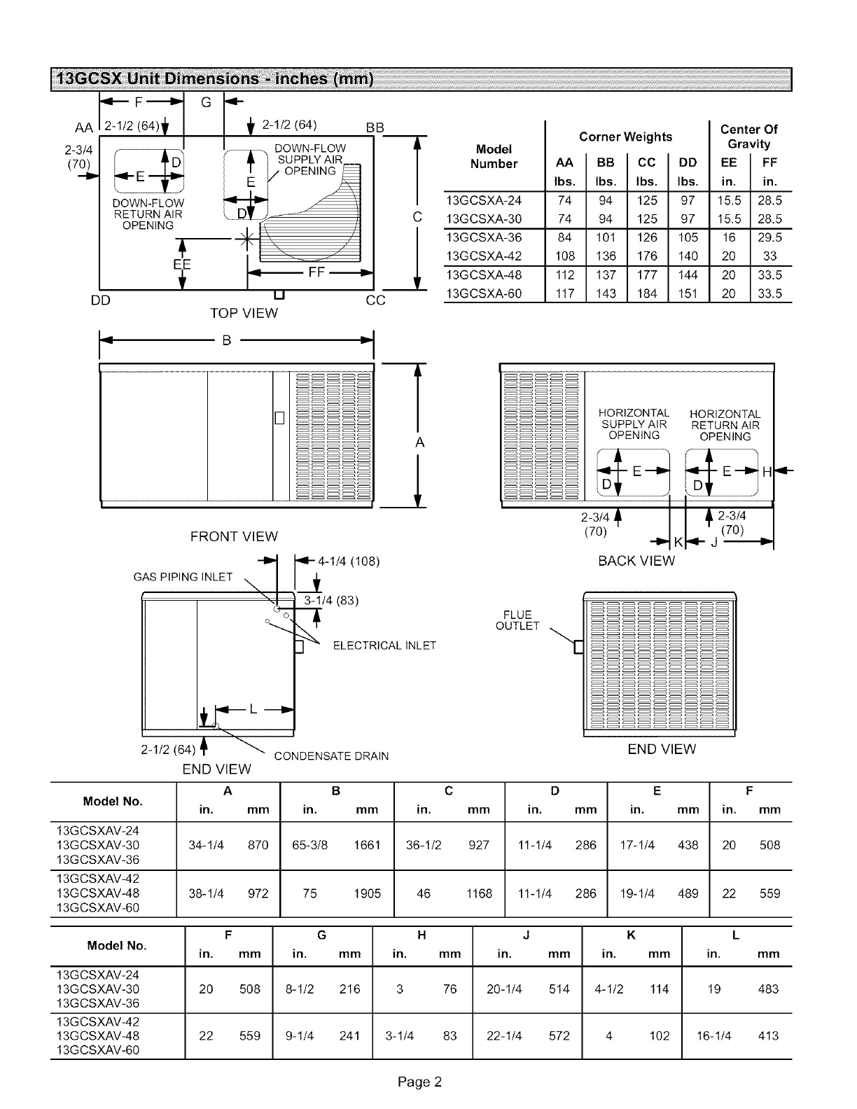
Model
Number
13GCSXA-24
13GCSXA-30
13GCSXA-36
13GCSXA-42
13GCSXA-48
13GCSXA-60
74
74
84
108
112
117
Corner Weights
125 97 15.5
125 97 15.5
126 105 16
176 140 20
177 144 20
184 151 20
94
94
101
136
137
143
Center Of
Gravity
FF
in.
28.5
28.5
29.5
33
33.5
33.5
9 B D,
A
FRONT VIEW
--'t
GAS PIPING INLET "'". I
%_ o
'4-4-1/4 (108)
J3-1/4 (83)
I
ELECTRICAL INLET
_.--- L---_
2-I/2(64)_i _ CONDENSATE DRAIN
FLUE
OUTLET
HORIZONTAL HORIZONTAL
SUPPLY AIR RETURN AIR
OPENING OPENING
- '_--- E---_ H
TD_T
2-3/4 _, _, 2-3/4
(70) (70)
--D.K _ j I_D.
BACK VIEW
END VIEW
END VIEW
A B C D E F
Model No. in. mm in. mm in. mm in. mm in. mm in. mm
13GCSXAV-24
13GCSXAV-30 34-1/4 870 65-3/8 1661 36-1/2 927 11-1/4 286 17-1/4 438 20 508
13GCSXAV-36
13GCSXAV-42
13GCSXAV-48 38-1/4 972 75 1905 46 1168 11-1/4 286 19-1/4 489 22 559
13GCSXAV-60
F G H J K L
Model No. in. mm in. mm in. mm in. mm in. mm in. mm
13GCSXAV-24
13GCSXAV-30 20 508 8-1/2 216 3 76 20-1/4 514 4-1/2 114 19 483
13GCSXAV-36
13GCSXAV-42
13GCSXAV-48 22 559 9-1/4 241 3-1/4 83 22-1/4 572 4 102 16-1/4 413
13GCSXAV-60
Page 2
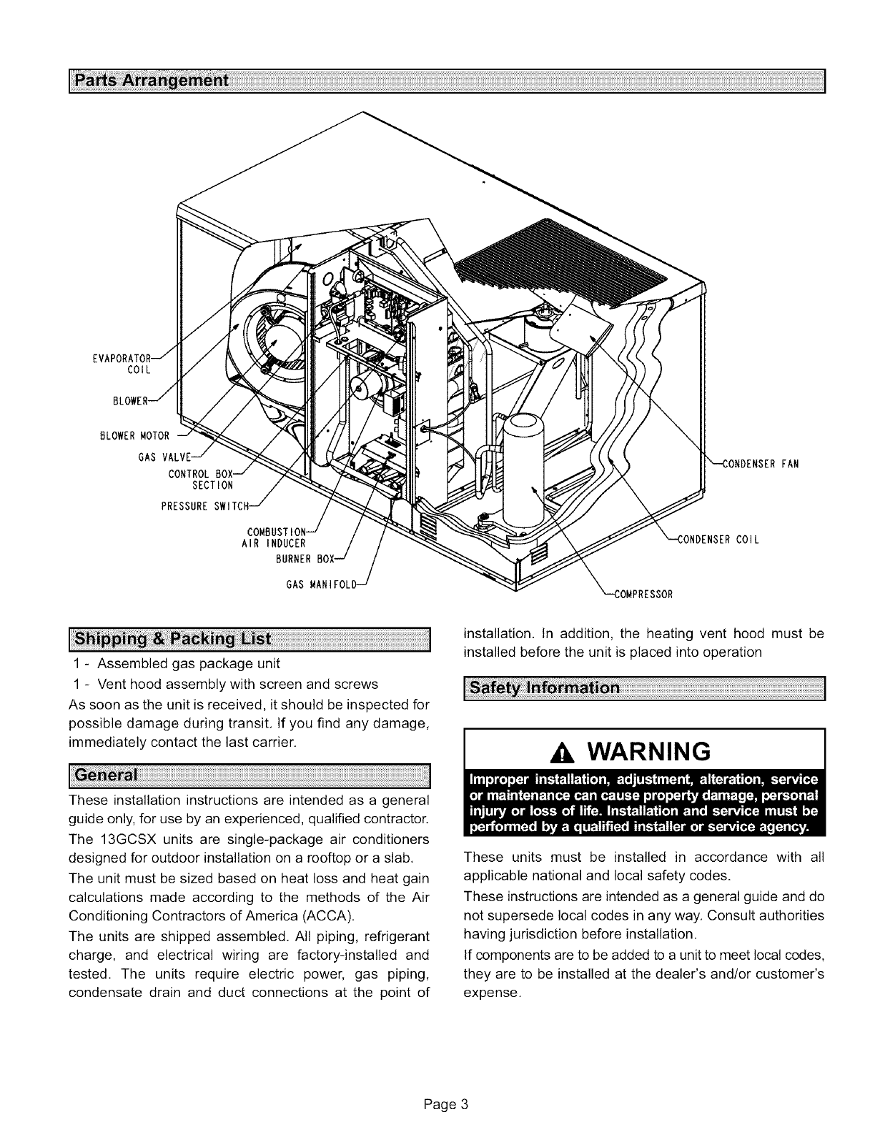
COIL
BLOWER MOTOR
GAS
CONTROL
SECTION
PRESSURE
AIR INDUCER
BURNER
GAS
COIL
FAN
1 - Assembled gas package unit
1 - Vent hood assembly with screen and screws
As soon as the unit is received, it should be inspected for
possible damage during transit, If you find any damage,
immediately contact the last carrier,
These installation instructions are intended as a general
guide only, for use by an experienced, qualified contractor.
The 13GCSX units are single-package air conditioners
designed for outdoor installation on a rooftop or a slab,
The unit must be sized based on heat loss and heat gain
calculations made according to the methods of the Air
Conditioning Contractors of America (ACCA).
The units are shipped assembled. All piping, refrigerant
charge, and electrical wiring are factory-installed and
tested. The units require electric power, gas piping,
condensate drain and duct connections at the point of
installation. In addition, the heating vent hood must be
installed before the unit is placed into operation
WARNING
These units must be installed in accordance with all
applicable national and local safety codes.
These instructions are intended as a general guide and do
not supersede local codes in any way, Consult authorities
having jurisdiction before installation.
If components are to be added to a unit to meet local codes,
they are to be installed at the dealer's and/or customer's
expense,
Page 3
A, WARNING
These units are design listed by UL in both the United
States and Canada as follows:
• For use as a forced air furnace with cooling,
• For outdoor installation only.
• For installation on combustible material.
• For use with natural gas or L,P./propane gas only. Use
of LP./propane gas requires installation of an LP, con-
version kit, which must be ordered separately,
These units are not suitable for use with conventional
venting systems.
The following safety requirements must also be met when
the 13GCSX units are installed:
1 - Use only with the type of fuel approved for use with this
appliance. Refer to the unit rating plate.
2 - Position, locate and install the 13GCSX unit only as
outlined in these instructions,
3 - Provide adequate clearance around the vent hood as
specified in these instructions.
4 - Do not use an open flame to check for gas leaks. Use a
commercially available soap solution, which has been
designed specifically to check for gas leaks, Refer to
the Gas Supply and Piping section,
5 - Check the unit operation after start-up to make sure
that the 13GCSX is operating within the intended tem-
perature rise range. The duct system must be de-
signed to provide an external static pressure within the
allowable range, Refer to the unit rating plate.
Lennox does not recommend the use of 13GCSX units as a
construction heater during any phase of construction. Very
low return air temperatures, harmful vapors and operation
of the unit with clogged or misplaced filters will damage the
unit,
13GCSX units may be used for heating of buildings or
structures under construction, if the following conditions
are met:
•The vent hood must be installed per these installation in-
structions.
• A room thermostat must control the unit. The use of
fixed jumpers that will provide continuous heating is not
allowed.
• The return air duct must be provided and sealed to the
unit.
• Return air temperature range between 60°F (16°C) and
80°F (27°C) must be maintained.
• Air filters must be installed in the system and must be
maintained during construction.
• Air filters must be replaced upon construction comple-
tion.
• The input rate and temperature rise must be set per the
unit rating plate.
•One hundred percent (100%) outdoor air must be pro-
vided for combustion air requirements during construc-
tion. Installation of this unit in its intended outdoor loca-
tion will accompfish this.
• The heat exchanger, components, duct system, air fil-
ters and evaporator coil must be thoroughly cleaned fol-
lowing final construction clean-up.
• The unit operating conditions (including ignition, input
rate, temperature rise and venting) must be verified ac-
cording to these instaflation instructions.
NOTE -The Commonwealth of Massachusetts stipu-
lates these additional requirements:
•Gas furnaces shall be installed by a licensed plumb-
er or gas fitter only.
•The gas cock must be "T handle" type.
•When flexible connectors are used, the maximum
length shall not exceed 36".
Use the following guidelines to select a suitable location for
these units.
1-Unit is designed for outdoor installation only. Unit must
be installed so all electrical components are protected
from water.
2-Condenser coils must have an unlimited supply of air.
3 - For ground level installation, use a level pre-fabricated
pad or use a level concrete slab with a minimum thick-
ness of 4 inches. The length and width should be at
least 6 inches greater than the unit base. Do not tie the
slab to the building foundation.
4 - Maintain level within a tolerance of 1/4 inch maximum
across the entire length or width of the unit.
Page 4
5- Donotlocatetheunitwherethecombustionairsupply
willbeexposedtoanycorrosivesubstance,including
thefollowing:
Permanentwavesolutions,
Chlorinatedwaxesorcleaners,
Chlorine-basedswimmingpoolchemicals,
Water-softeningchemicals,
De-icingsaltsorchemicals,
Carbontetrachloride,
Halogen-typerefrigerants,
Cleaningsolvents(e.g.,perchloroethylene),
Printinginks,paintremovers,varnishes,etc.,
Cementsandglues,
Anti-staticfabricsoftenersusedinclothesdryers,
Masonryacid-washingmaterials,
Chlorinatedlaundryproducts,
Hydrochloricacid.
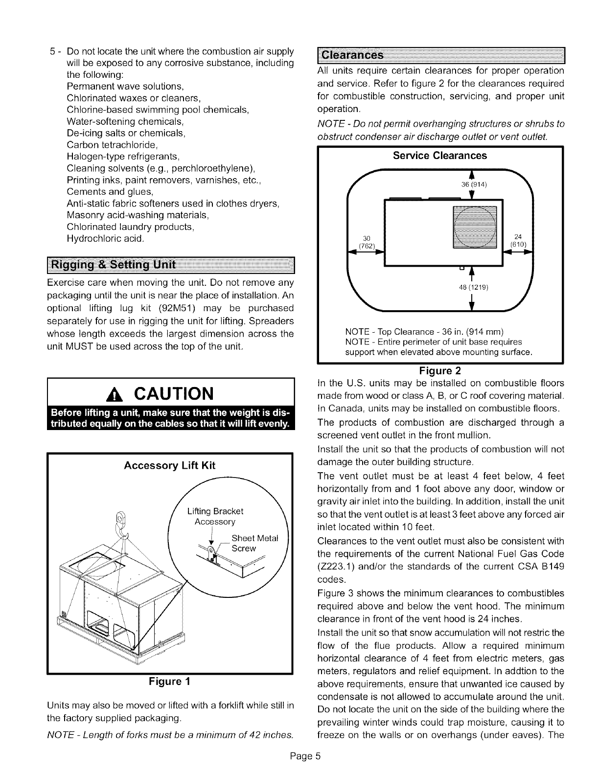
Exercisecarewhenmovingtheunit.Donotremoveany
packaginguntiltheunitisneartheplaceofinstallation.An
optionallifting lug kit (92M51)may be purchased
separatelyforuseinriggingtheunitforlifting.Spreaders
whoselengthexceedsthelargestdimensionacrossthe
unitMUSTbeusedacrossthetopof theunit.
CAUTION
Accessory Lift Kit
Figure 1
Units may also be moved or lifted with a forklift while still in
the factory supplied packaging.
NOTE -Length of forks must be a minimum of 42 inches.
Page
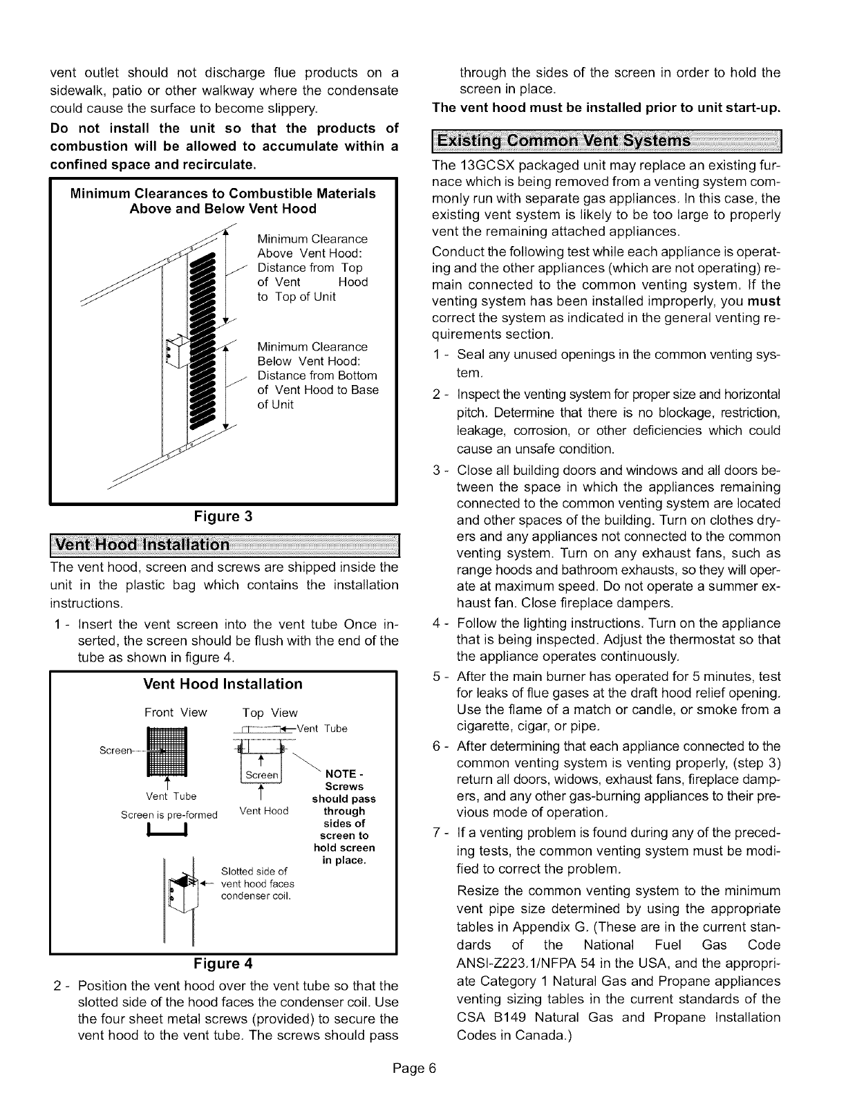
All units require certain clearances for proper operation
and service. Refer to figure 2 for the clearances required
for combustible construction, servicing, and proper unit
operation.
NOTE -Do not permit overhanging structures or shrubs to
obstruct condenser air discharge outlet or vent outleL
Service Clearances
36 (914)
48 (1219)
NOTE - Top Clearance - 36 in. (914 mm)
NOTE - Entire perimeter of unit base requires
support when elevated above mounting surface.
Figure 2
In the U.S. units may be installed on combustible floors
made from wood or class A, B, or C roof covering material.
In Canada, units may be installed on combustible floors.
The products of combustion are discharged through a
screened vent outlet in the front mullion.
Install the unit so that the products of combustion will not
damage the outer building structure.
The vent outlet must be at least 4 feet below, 4 feet
horizontally from and 1 foot above any door, window or
gravity air inlet into the building. In addition, install the unit
so that the vent outlet is at least 3 feet above any forced air
inlet located within 10 feet.
Clearances to the vent outlet must also be consistent with
the requirements of the current National Fuel Gas Code
(Z223.1) and/or the standards of the current CSA B149
codes.
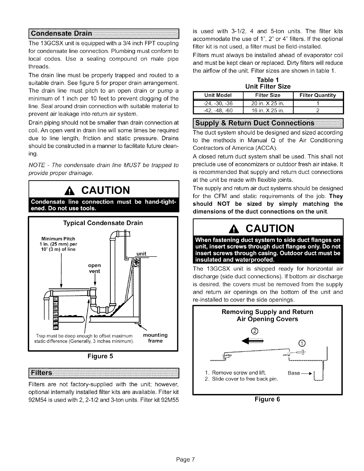
Figure 3 shows the minimum clearances to combustibles
required above and below the vent hood. The minimum
clearance in front of the vent hood is 24 inches.
Install the unit so that snow accumulation will not restric the
flow of the flue products. Allow a required minimum
horizontal clearance of 4 feet from electric meters, gas
meters, regulators and relief equipment. In addtion to the
above requirements, ensure that unwanted ice caused by
condensate is not allowed to accumulate around the unit.
Do not locate the unit on the side of the building where the
prevailing winter winds could trap moisture, causing it to
freeze on the walls or on overhangs (under eaves). The
vent outletshouldnot dischargeflue productson a
sidewalk,patioor otherwalkwaywherethe condensate
couldcausethesurfacetobecomeslippery.
Do not install the unit so that the products of
combustionwill be allowedto accumulatewithin a
confinedspaceandrecirculate.
Minimum Clearances to Combustible Materials
Above and Below Vent Hood
Minimum Clearance
Above Vent Hood:
Distance from Top
of Vent Hood
to Top of Unit
Minimum Clearance
Below Vent Hood:
Distance from Bottom
of Vent Hood to Base
of Unit
Figure 3
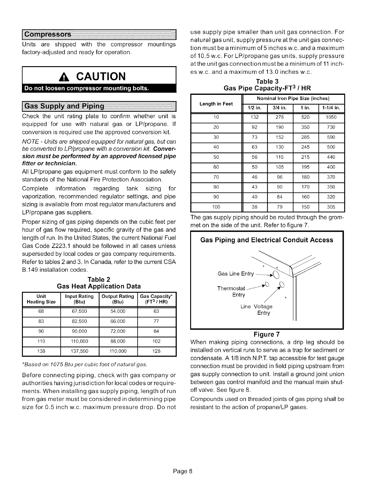
The vent hood, screen and screws are shipped inside the
unit in the plastic bag which contains the installation
instructions.
1 - Insert the vent screen into the vent tube Once in-
serted, the screen should be flush with the end of the
tube as shown in figure 4.
Vent Hood Installation
Front View Top View
_Vent Tube
NOTE -
Screws
Vent Tube '_ should pass
Screen is pre-formed Vent Hood through
sides of
screen to
hold screen
_'_ in place.
i Slotted side of
vent hood faces
condenser coil.
Figure 4
2 - Position the vent hood over the vent tube so that the
slotted side of the hood faces the condenser coil. Use
the four sheet metal screws (provided) to secure the
vent hood to the vent tube. The screws should pass
through the sides of the screen in order to hold the
screen in place.
The vent hood must be installed prior to unit start-up.
The 13GCSX packaged unit may replace an existing fur-
nace which is being removed from a venting system com-
monly run with separate gas appliances. In this case, the
existing vent system is likely to be too large to properly
vent the remaining attached appliances.
Conduct the following test while each appliance is operat-
ing and the other appliances (which are not operating) re-
main connected to the common venting system. If the
venting system has been installed improperly, you must
correct the system as indicated in the general venting re-
quirements section.
1 - Seal any unused openings in the common venting sys-
tem.
2 - Inspect the venting system for proper size and horizontal
pitch. Determine that there is no blockage, restriction,
leakage, corrosion, or other deficiencies which could
cause an unsafe condition.
3 - Close all building doors and windows and all doors be-
tween the space in which the appliances remaining
connected to the common venting system are located
and other spaces of the building. Turn on clothes dry-
ers and any appliances not connected to the common
venting system. Turn on any exhaust fans, such as
range hoods and bathroom exhausts, so they will oper-
ate at maximum speed. Do not operate a summer ex-
haust fan. Close fireplace dampers.
4 - Follow the lighting instructions. Turn on the appliance
that is being inspected. Adjust the thermostat so that
the appliance operates continuously.
5 - After the main burner has operated for 5 minutes, test
for leaks of flue gases at the draft hood relief opening.
Use the flame of a match or candle, or smoke from a
cigarette, cigar, or pipe.
6 - After determining that each appliance connected to the
common venting system is venting properly, (step 3)
return all doors, widows, exhaust fans, fireplace damp-
ers, and any other gas-burning appliances to their pre-
vious mode of operation.
7 - If a venting problem is found during any of the preced-
ing tests, the common venting system must be modi-
fied to correct the problem.
Resize the common venting system to the minimum
vent pipe size determined by using the appropriate
tables in Appendix G. (These are in the current stan-
dards of the National Fuel Gas Code
ANSFZ223.1/NFPA 54 in the USA, and the appropri-
ate Category 1 Natural Gas and Propane appliances
venting sizing tables in the current standards of the
CSA B149 Natural Gas and Propane Installation
Codes in Canada.)
Page 6
The13GCSXunitisequippedwitha 3/4inchFPTcoupling
forcondensatelineconnection.Plumbingmustconformto
local codes.Use a sealingcompoundon malepipe
threads.
Thedrainlinemustbeproperlytrappedandroutedtoa
suitabledrain.Seefigure5forproperdrainarrangement.
Thedrainlinemustpitchto anopendrainor pumpa
minimumof 1inchper10feetto preventcloggingofthe
line.Sealarounddrainconnectionwithsuitablematerialto
preventairleakageintoreturnairsystem.
Drainpipingshouldnotbesmallerthandrainconnectionat
coil.Anopenventindrainlinewillsometimesberequired
dueto line length,frictionand staticpressure.Drains
shouldbeconstructedinamannertofacilitatefutureclean-
ing.
NOTE -The condensate drain line MUST be trapped to
provide proper drainage.
CAUTION
vent
Trap must be deep enough to offset maximum
static difference (Generally, 3 inches minimum).
Typical Condensate Drain
Minimum Pitch
1 in. (25 ram) per
10' (3 m) of line unit
open
mounting
frame
Figure 5
Filters are not factory-supplied with the unit; however,
optional internally installed filter kits are available. Filter kit
92M54 is used with 2, 2-1/2 and 3-ton units. Filter kit 92M55
is used with 3-1/2, 4 and 5-ton units. The filter kits
accommodate the use of 1", 2" or 4" filters. If the optional
filter kit is not used, a filter must be field-installed,
Filters must always be installed ahead of evaporator coil
and must be kept clean or replaced, Dirty filters will reduce
the airflow of the unit, Filter sizes are shown in table 1.
Table 1
Unit Filter Size
Unit Model Filter Size Filter Quantity
-24, -30, -36 20 in. X 25 in. 1
-42, -48, -60 16 in. X 25 in. 2
The duct system should be designed and sized accordin(
to the methods in Manual Q of the Air Conditionin(
Contractors of America (ACCA).
A closed return duct system shall be used. This shall not
preclude use of economizers or outdoor fresh air intake. It
is recommended that supply and return duct connections
at the unit be made with flexible joints.
The supply and return air duct systems should be designed
for the CFM and static requirements of the job. They
should NOT be sized by simply matching the
dimensions of the duct connections on the unit.
A CAUTION
The 13GCSX unit is shipped ready for horizontal air
discharge (side duct connections). If bottom air discharge
is desired, the covers must be removed from the supply
and return air openings on the bottom of the unit and
re-installed to cover the side openings.
Removing Supply and Return
Air Opening Covers
®
®
1. Remove screw and lift. Base-_ I
2. Slide cover to free back pin. U
Figure 6
Page 7
Units are shippedwith the compressormountings
factory-adjustedandreadyforoperation.
CAUTION
Check the unit rating plate to confirm whether unit is
equipped for use with natural gas or LP/propane. If
conversion is required use the approved conversion kit,
NQ TE -Units are shipped equipped for natural gas, but can
be converted to LP/propane with a conversion kit. Conver-
sion must be performed by an approved licensed pipe
fitter or technician.
All LP/propane gas equipment must conform to the safety
standards of the National Fire Protection Association.
Complete information regarding tank sizing for
vaporization, recommended regulator settings, and pipe
sizing is available from most regulator manufacturers and
LP/propane gas suppliers.
Proper sizing of gas piping depends on the cubic feet per
hour of gas flow required, specific gravity of the gas and
length of run, In the United States, the current National Fuel
Gas Code Z223.1 should be followed in all cases unless
superseded by local codes or gas company requirements.
Refer to tables 2 and 3, In Canada, refer to the current CSA
B,149 installation codes,
Table 2
Gas Heat Application Data
Unit Input Rating Output Rating Gas Capacity*
Heating Size (Btu) (Btu) (FT3/HR)
68 67,500 54,000 63
83 82,500 66,000 77
90 90,000 72,000 84
110 110,000 88,000 102
138 137,500 110,000 128
*Based on 1075 Btu per cubic foot of natural gas.
Before connecting piping, check with gas company or
authorities having jurisdiction for local codes or require-
ments, When installing gas supply piping, length of run
from gas meter must be considered in determining pipe
size for 0,5 inch w,c, maximum pressure drop, Do not
use supply pipe smaller than unit gas connection. For
natural gas unit, supply pressure at the unit gas connec-
tion must be a minimum of 5 inches w,c, and a maximum
of 10.5 w.c. For LP/propane gas units, supply pressure
at the unit gas connection must be a minimum of 11 inch-
esw.c, and a maximum of 13,0 inches w,c,
Table 3
Gas Pipe Capacity-FT 3 /HR
Nominal Iron Pipe Size (inches)
Length in Feet 1/2 in.
10 132
20 92
30 73
40 63
50 56
60 50
70 46
80 43
90 40
1O0 38
3/4in. 1 in. 1-1/4 in.
278 520 1050
190 350 730
152 285 590
130 245 500
115 215 440
105 195 400
96 180 370
90 170 350
84 160 320
79 150 305
The gas supply piping should be routed through the grom-
met on the side of the unit, Refer to figure 7,
Gas Piping and Electrical Conduit Access
Gas
Thermostat _(5/_(_
Entry J o
/
Line Voltage
Entry
Figure 7
When making piping connections, a drip leg should be
installed on vertical runs to serve as a trap for sediment or
condensate, A 1/8 inch N,RT. tap accessible for test gauge
connection must be provided in field piping upstream from
gas supply connection to unit. Install a ground joint union
between gas control manifold and the manual main shut-
off valve. See figure 8,
Compounds used on threaded joints of gas piping shall be
resistant to the action of propane/LP gases,
Page 8
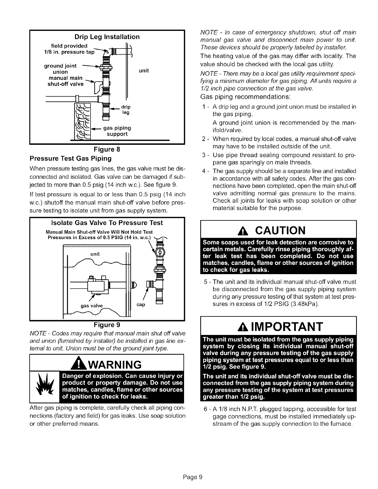
Drip Leg Installation
field provided
1/8 in. !
ground joint
union
manual main
shut-off
unit
I_ leg
gas piping
support
Figure 8
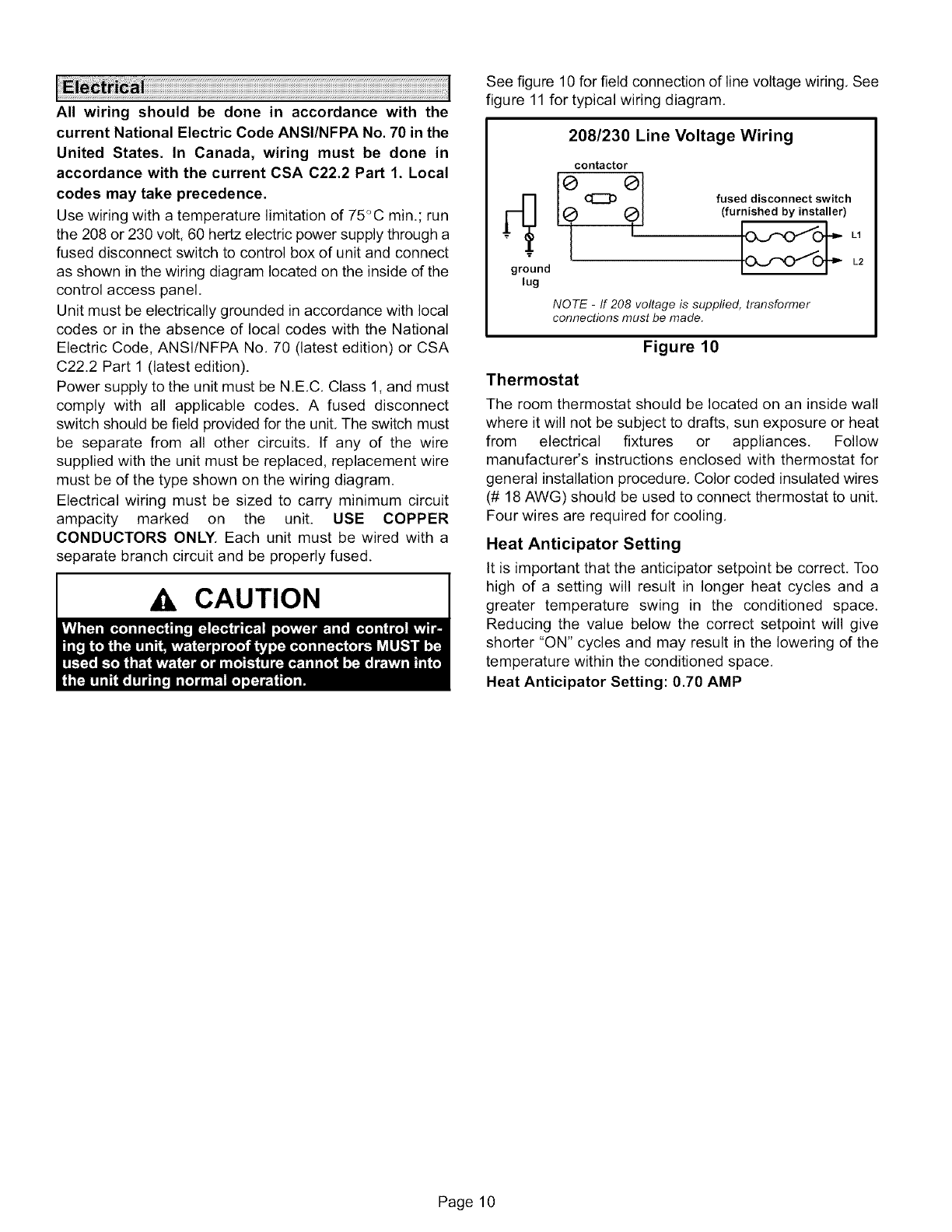
Pressure Test Gas Piping
When pressure testing gas lines, the gas valve must be dis-
connected and isolated. Gas valve can be damaged if sub-
jected to more than 0,5 psig (14 inch w,c,), See figure 9.
If test pressure is equal to or less than 0,5 psig (14 inch
w.c,) shutoff the manual main shut-off valve before pres-
sure testing to isolate unit from gas supply system,
Isolate Gas Valve To Pressure Test
Manual Main Shut-off Valve Will Not Hold Test
Pressures in Excess of 0.5 PSIG (14 in. w.c.)
unit
gas valve cap
Figure 9
NOTE -Codes may require that manual main shut off valve
and union (furnished by installer) be installed in gas line ex-
ternal to unit, Union must be of the ground joint type,
, WARNING
After gas piping is complete, carefully check all piping con-
nections (factory and field) for gas leaks. Use soap solution
or other preferred means.
NOTE -In case of emergency shutdown, shut off main
manual gas valve and disconnect main power to unit,
These devices should be properly labeled by installer.
The heating value of the gas may differ with locality, The
value should be checked with the local gas utility.
NOTE -There may be a local gas utility requirement speci-
fying a minimum diameter for gas piping. All units require a
1/2 inch pipe connection at the gas valve,
Gas piping recommendations:
1 - A drip leg and a ground joint union must be installed in
the gas piping.
A ground joint union is recommended by the man-
ifold/valve,
2 - When required by local codes, a manual shut-off valve
may have to be installed outside of the unit,
3 - Use pipe thread sealing compound resistant to pro-
pane gas sparingly on male threads,
4 - The gas supply should be a separate line and installed
in accordance with all safety codes. After the gas con-
nections have been completed, open the main shut-off
valve admitting normal gas pressure to the mains,
Check all joints for leaks with soap solution or other
material suitable for the purpose,
CAUTION
5 -The unit and its individual manual shut-off valve must
be disconnected from the gas supply piping system
during any pressure testing of that system at test pres-
sures in excess of 1/2 PSIG (3,48kPa).
AIMPORTANT
6 - A 1/8 inch N.RT. plugged tapping, accessible for test
gage connections, must be installed immediately up-
stream of the gas supply connection to the furnace.
Page 9
All wiring should be done in accordance with the
current National Electric Code ANSI/NFPA No. 70 in the
United States. In Canada, wiring must be done in
accordance with the current CSA C22.2 Part 1. Local
codes may take precedence.
Use wiring with a temperature limitation of 75_C min.; run
the 208 or 230 volt, 60 hertz electric power supply through a
fused disconnect switch to control box of unit and connect
as shown in the wiring diagram located on the inside of the
control access panel,
Unit must be electrically grounded in accordance with local
codes or in the absence of local codes with the National
Electric Code, ANSI/NFPA No. 70 (latest edition) or CSA
C22.2 Part 1 (latest edition).
Power supply to the unit must be N.E,C, Class 1, and must
comply with all applicable codes. A fused disconnect
switch should be field provided for the unit, The switch must
be separate from all other circuits, If any of the wire
supplied with the unit must be replaced, replacement wire
must be of the type shown on the wiring diagram.
Electrical wiring must be sized to carry minimum circuit
ampacity marked on the unit. USE COPPER
CONDUCTORS ONLY. Each unit must be wired with a
separate branch circuit and be properly fused.
CAUTION
See figure 10 for field connection of line voltage wiring, See
figure 11 for typical wiring diagram.
208/230 Line Voltage Wiring
contactor
__ (:_ fused disconnect switch
(furnished by installer)
T
ground L2
lug
NOTE -ff 208 voltage is supplied, transformer
connections must be made.
Figure 10
Thermostat
The room thermostat should be located on an inside wall
where it will not be subject to drafts, sun exposure or heat
from electrical fixtures or appliances. Follow
manufacturer's instructions enclosed with thermostat for
general installation procedure. Color coded insulated wires
(# 18 AWG) should be used to connect thermostat to unit.
Four wires are required for cooling.
Heat Anticipator Setting
It is important that the anticipator setpoint be correct. Too
high of a setting will result in longer heat cycles and a
greater temperature swing in the conditioned space.
Reducing the value below the correct setpoint will give
shorter "ON" cycles and may result in the lowering of the
temperature within the conditioned space.
Heat Anticipator Setting: 0.70 AMP
Page 10
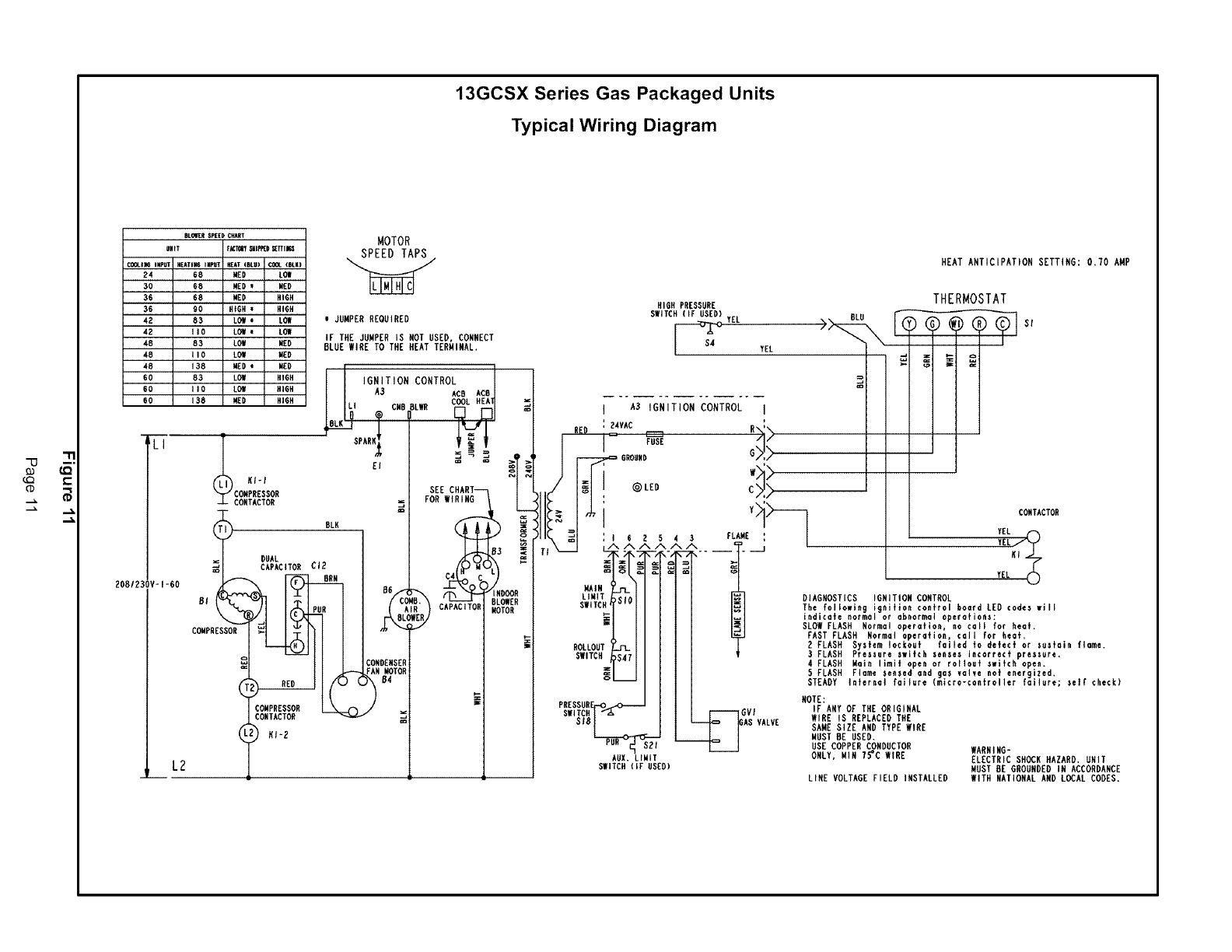
13GCSX Series Gas Packaged Units
Typical Wiring Diagram
m.Ol[_ SPEED¢_ART
UIItT fKlr_ al_lOD _TTim
¢OGLI_,6iNPUT HEATtN6 INPUT HEAT(BLU) ,COOl.(HI.K)
24 68 WED LOW
30 68 WED I NED
36 68 NED HIGH
36 90 HtGHt HIGH
4E 83 LOW oLOH
42 I I 0 LOWILOW
48 83 LOW WED
48 I I 0 LOW WED
48 138 WED i HEO
60 83 LO!it HIGH
60 I I 0 LQW HIGH
GO t38 NED HIGH
LI
L2
ZOB/ZSOV-l-6O
COMPRESSOR
CONTACTON
_T BLK
DUAL
CAPACITOR CI?
m
COMPRESSOR
MOTOR
uJUMPER REQUIRED
IF THE JUMPER IS HOT USED, CONNECT
BLUE WIRE TO THE HEAT TERMINAL.
iGNiTiON CONTROL I
I I AS ACB ACBI
J
SEE C HAg T----I
_Wi= FOR WIRING
COMUENS
HEAT ANTICIPATION SETTING: 0.70 AMP
HIGH PRESSURE THERMOSTAT
SWITCH (IF USED) YEL BLU
, As,G 5 O C5 I I ]I]
:.VAC :- _ I _ I 1
r-- G=HU G I> | 1 I 1
" _ H254 3 FLAW{ :
WAIN
LINt DIAGNOSTICS IGNITION CONTROL
SWITCH'T_"I II l I_] The following ignition control board LEO codes will
_-I I I I I I=1 indicate normal or abnormal operafionz:
_=1 I JI I I_] SLOW FLASH Normal operation, no call for heat.
.L III I _ FAST FLASH Normol oper_Jfio_, colt for heat.
ROLLOUT_ I I ] [ | g FLASH System IockouE failed to defect or sestain flame.
SWITCH _47 [ I _| t 3 FLASH Pressure switch senses incorrect pressure,
_'" I Il I 4 FLASH Mai_ limit open or rollout switch open.
_I I II I 5FLASH Flame sensed and gas valve nor energized.
'I II STEADY,nter0o,fo. r.*°icro-cootro,lertai,ure;s..c.c.
PN NNOTE:
•EW_T_e_UFI_"_'--"--I Il GVI IF ANY OF THE ORIGINAL
_"'_'/_l -I h_..E_-_.l_v .... WIRE IS REPLACED THE
" -1 J |-- |........ SAME SIZE AND TYPE WIRE
_IMUST BE USED.
PUU_l_ "S_Pl _ USE COPPER CONDUCTOR wer_e_uc
-- ONLY, WIN 75"C WIRE ....... "
AUX. LIMIT ELECTRIC SH_K HAZARD, UNIT
SWITCH(IF USED) MUST BE GROUNDEDIN ACCORDANCE
LINE VOLTAGE FIELD INSTALLED WITH NATIONAL AND LOCAL CODES.
WARNING I
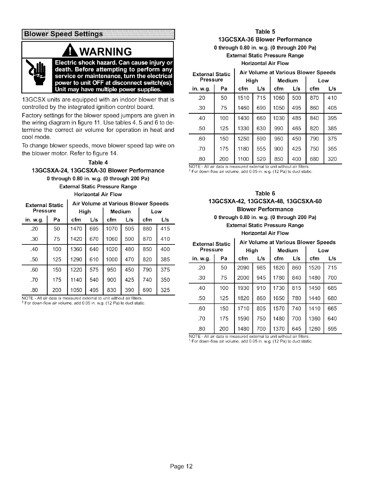
13GCSX units are equipped with an indoor blower that is
controlled by the integrated ignition control board.
Factory settings for the blower speed jumpers are given in
the wiring diagram in figure 11. Use tables 4, 5 and 6 to de-
termine the correct air volume for operation in heat and
cool mode.
To change blower speeds, move blower speed tap wire on
the blower motor. Refer to figure 14.
Table 4
13GCSXA-24, 13GCSXA-30 Blower Performance
0through 0.80 in. w.g. (0 through200 Pa)
ExternalStatic Pressure Range
HorizontalAir Flow
Air Volume at Various Blower Speeds
High
cfm L/s
1470 695
1420 670
1360 640
1290 610
External Static
Pressure
1220 575 950 450 790
1140 540 900 425 740
1050 495 830 390 690
Medium Low
cfm L/s cfm L/s
1070 505 880 415
1060 500 870 410
1020 480 850 400
1000 470 820 385
375
35O
325
in. w.g.
.20 50
.30 75
.40 100
.50 125
.60 150
.70 175
.80 200
NOTE - All air data is measured external to unit without air filters.
1 For down-flow air volume, add 0.05 in. w.g. (12 Pa) to duct static.
Table 5
13GCSXA-36 Blower Performance
0through 0.80 in. w.g. (0 through 200 Pa)
External Static Pressure Range
Horizontal Air Flow
External Static Air Volume at Various Blower Speeds
Pressure High Medium Low
in. w.g.
.20 50
.30 75
.40 100
.50 125
.60 150
.70 175
.80 200
cfm
1510
1460
1400
1330
1250
1180
1100
L/s cfm
715 1060
690 1050
660 1030
630 990
590 950
555 900
520 850
L/s cfm
500 870
495 860
485 840
465 820
450 790
425 750
400 680
NOTE - All air data is measured external to unit without air filters,
1 For down-flow air volume, add 0.05 in. w.g. (12 Pa) to duct static.
L/s
410
4O5
395
385
375
355
32O
Table 6
13GCSXA-42, 13GCSXA-48, 13GCSXA-60
Blower Performance
0 through 0.80 in. w.g. (0 through 200 Pa)
External Static Pressure Range
Horizontal Air Flow
External Static
Pressure
in. w.g.
.20 50
.30 75
.40 100
.50 125
.60 150
.70 175
.80 200
2090 985
2000 945
1930 910
1820 860
1710 805
1590 750
1480 700
1820 860 1520
1780 840 1480
1730 815 1450
1650 780 1440
1570 740 1410
1480 700 1360
1370 645 1260
Air Volume at Various Blower Speeds
High Medium Low
cfm L/s cfm L/s cfm L/s
715
7OO
685
68O
665
64O
595
NOTE - All air data is measured external to unit without air filters,
1 For down-flow air volume, add 0.05 in. w.g. (12 Pa) to duct static.
Page 12
Thecoolingsectionisacompletefactorypackageutilizing
anair-cooledcondenser.Thesystemisfactory-charged
withR-410Arefrigerant.Thecompressoris hermetically
sealed, internallysprung and base-mountedwith
rubber-insolatedhold-downbolts.
Pre-Start Check List:
1 - Make sure refrigerant lines do not rub against the cabi-
net or each other.
2- Inspect all electrical wiring, both factory- and field-
installed, for loose connections.
3 - Check voltage at the disconnect switch. Voltage must
be within the range listed on the unit nameplate. If not,
consult power company and have voltage condition
corrected before starting unit.
4 - Recheck voltage with unit running. If power is not with-
in the range listed on the unit nameplate, stop the unit
and consult the power company. Check unit amper-
age. Refer to unit nameplate for correct running amps.
5 - Make sure filter is in place before unit start-up.
6 - Before placing the unit into full operation, energize the
unit for three false starts. Energize the compressor
just long enough for it to make a few revolutions, wait
five to seven minutes before repeating a second and
third time.
Cooling Sequence of Operation
When the thermostat calls for cooling, "R" is closed to "G"
and "Y" (figure 11). This completes the low voltage control
circuit, energizing the compressor, condenser fan motor
and blower motor.
NOTE -At the start of the each cooling demand, the
combustion air blower (draft motor) will operate for 10
seconds.
Unit compressors have internal protection. If there is an
abnormal rise in the compressor temperature, the
protector will open and the compressor will stop.
Blower Delay -Cooling
In the cooling mode, the circulating air blower operation is
delayed for 5 seconds after the compressor starts. The
blower continues to operate for 90 seconds after the
compressor is de-energized.
NOTE -With the proper thermostat and subbase, continu-
ous blower operation is possible by closing the R to G cir-
cull Cooling blower delay is also functional in this mode.
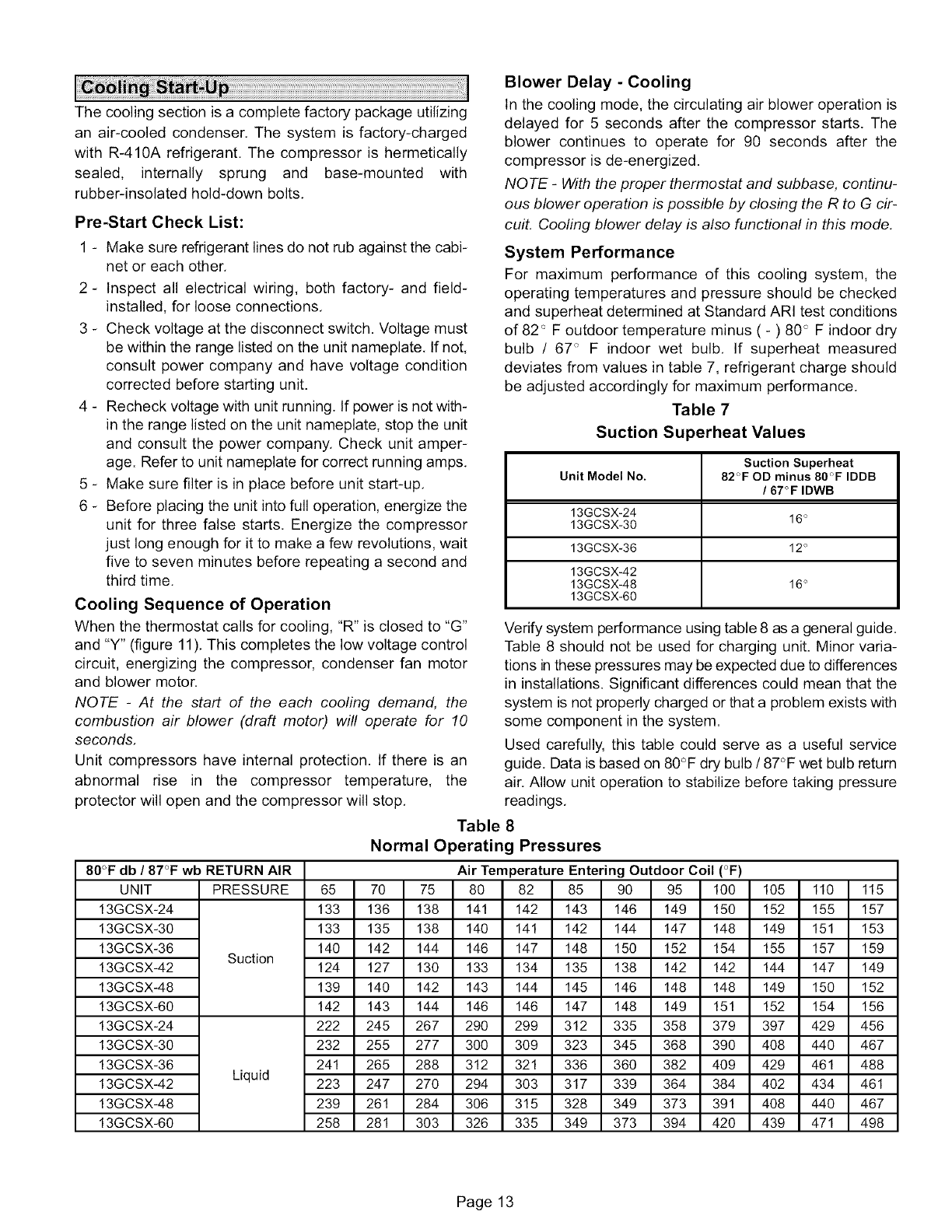
System Performance
For maximum performance of this cooling system, the
operating temperatures and pressure should be checked
and superheat determined at Standard ARI test conditions
of 82 '_ F outdoor temperature minus ( - ) 80 ° F indoor dry
bulb /67 <_F indoor wet bulb. If superheat measured
deviates from values in table 7, refrigerant charge should
be adjusted accordingly for maximum performance.
Table 7
Suction Superheat Values
Suction Superheat
Unit Model No. 82°F OD minus 80"F IDDB
/67"F IDWB
13GCSX-24
13GCSX-30 16"
13GCSX-36 12 °
13GCSX-42
13GCSX-48 16 °
13GCSX-60
Verify system performance using table 8 as a general guide.
Table 8 should not be used for charging unit. Minor varia-
tions in these pressures may be expected due to differences
in installations. Significant differences could mean that the
system is not properly charged or that a problem exists with
some component in the system.
Used carefully, this table could serve as a useful service
guide. Data is based on 80°F dry bulb /87°F wet bulb return
air. Allow unit operation to stabilize before taking pressure
readings.
80°F db/ 87°F wb RETURN AIR
UNIT PRESSURE
13GCSX-24
13GCSX-30
13GCSX-36 Suction
13GCSX-42
13GCSX-48
13GCSX-60
13GCSX-24
13GCSX-30
13GCSX-36
13GCSX-42 Liquid
13GCSX-48
13GCSX-60
Table 8
Normal Operating Pressures
Air Temperature Entering Outdoor Coil (°F)
65 70 75 80 82 85 90 95 100 105 110 115
133 136 138 141 142 143 146 149 150 152 155 157
133 135 138 140 141 142 144 147 148 149 151 153
140 142 144 146 147 148 150 152 154 155 157 159
124 127 130 133 134 135 138 142 142 144 147 149
139 140 142 143 144 145 146 148 148 149 150 152
142 143 144 146 146 147 148 149 151 152 154 156
222 245 267 290 299 312 335 358 379 397 429 456
232 255 277 300 309 323 345 368 390 408 440 467
241 265 288 312 321 336 360 382 409 429 461 488
223 247 270 294 303 317 339 364 384 402 434 461
239 261 284 306 315 328 349 373 391 408 440 467
258 281 303 326 335 349 373 394 420 439 471 498
Page 13
Pre-Start Check List:
1 - Check the type of gas being supplied, Be sure it is the
same as listed on the unit nameplate,
2 - Make sure the vent hood has been properly installed,
FOR YOUR SAFETY READ BEFORE LIGHTING
BEFORE LIGHTING the unit, smell all around the fur-
nace area for gas. Be sure to smell next to the floor be-
cause some gas is heavier than air and will settle on the
floor,
,WARNING
IkWARNING
,WARNING
WARNING
The gas valve on may be equipped with either a gas con-
trol switch or gas control knob, Use only your hand to
push the switch or turn the gas control knob. Never use
tools. If the the switch will not move or the knob will not
push in or turn by hand, do not try to repair it. Call a quali-
fied service techni clan, Force or attempted repair may
result in a fire or explosion,
This unit is equipped with a direct ignition control, Do not
attempt to manually light the burners,
1 - Turn off electrical power to unit.
2 - Set thermostat to lowest setting,
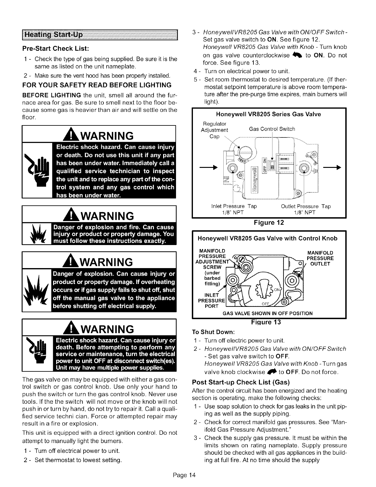
3 - HoneywellVR8205 Gas Valve with ON/OFF Switch -
Set gas valve switch to ON. See figure 12.
Honeywell VR8205 Gas Valve with Knob - Turn knob
on gas valve counterclockwise _1_ to ON, Do not
force. See figure 13.
4 - Turn on electrical power to unit.
5 - Set room thermostat to desired temperature, (If ther-
mostat setpoint temperature is above room tempera-
ture after the pre-purge time expires, main burners will
light),
Honeywell VR8205 Series Gas Valve
Regulator
Adjustment
..........................................
Gas Control Switch
Inlet Pressure Tap
1/8" NPT
Outlet Pressure Tap
1/8" NPT
Figure 12
Honeywell VR8205 Gas Valve with Control Knob
MANIFOLD
PRESSURE _\_
ADJ USTM ENT'_-?,--_ _ 4"
SCREW I)
(under I..=1."_'_
barbed _("1:3"_ ./I" _\
fitting) ' ON
PRESSUREI _ _ /.,4
PORT I -I k_(" OFFj//,
MANIFOLD
GAS VALVE SHOWN IN OFF POSITION
Fiqure 13
To Shut Down:
1 - Turn off electric power to unit.
2 - HoneywellVR8205 Gas Valve with ON/OFF Switch
- Set gas valve switch to OFF,
Honeywell VR8205 Gas Valve with Knob -Turn gas
valve knob clockwise _1_ to OFF. Do not force.
Post Start-up Check List (Gas)
After the control circuit has been energized and the heating
section is operating, make the following checks:
1 - Use soap solution to check for gas leaks in the unit pip-
ing as well as the supply piping,
2 - Check for correct manifold gas pressures, See "Man-
ifold Gas Pressure Adjustment."
3 - Check the supply gas pressure. It must be within the
limits shown on rating nameplate. Supply pressure
should be checked with all gas appliances in the build-
ing at full fire, At no time should the supply
Page 14
gaspressureexceed10.5inchesw,c,,nordropbelow
5.0inchesw.c.fornaturalgasunits,Forpropanegas,
supplygaspressureshouldnotdropbelow11inches
w.c.If gaspressureis outsidetheselimits,contact
yourgassupplierforcorrectiveaction,
4 - Adjusttemperaturerisetotherangespecifiedonthe
ratingplate.
Checking and Adjusting Gas Input
NOTE -Units must be converted for use with LP/propane
gas, Conversion kit is ordered separately, Conversion
must be performed by an approved licensed pipe fitter
or technician.
The minimum permissible gas supply pressure is 5,0
inches W.C. for natural gas or 11,0 inches W.C. for
LP/propane gas, The maximum inlet gas supply pressure
is 10.5 inches W.C. for natural gas and 13,0 inches W.C. for
LP/propane gas. Gas input must never exceed the input
capacity shown on the rating plate.
Units fueled by natural gas are rated for manifold pressures
of 3,5 inches W,C,
Units fueled by LP/propane gas are rated for manifold
pressures of 10.0 inches W,C,
Measure manifold pressure: Shut off gas supply to the
unit. Remove plug from pressure tap, See figure 12 or 13.
Connect manometer or gauge to the proper pressure tap,
then turn on the gas supply,
The Honeywell VR8205 gas valve has an adjusting screw.
See figure 12 or 13 for adjusting screw location, Remove
the cap and turn the adjusting screw clockwise to increase
pressure and input; turn counterclockwise to decrease
pressure and input. The pressure regulator adjustment is
sensitive. One turn dthe adjusting screw results in a large
change in manifold pressure. Replace the adjusting screw
cap.
Final manifold pressure must be within the allowable range
for the gas being used.
For Natural Gas: Check the furnace rate by observing gas
meter, making sure all other gas appliances are turned off.
The test hand on the meter should be timed for at least one
revolution. Note the number of seconds for one revolution,
BTU/HR = Cubic Feet Per Revolution X 3600 X Heating Value
INPUT No. Seconds Per Revolution
The heating value of your gas can be obtained from your
local utility.
For LP/Propane Gas: The only check for the output rate is
to properly adjust the manifold pressure using a manome-
ter, Typical manifold setpoint for installations at altitudes
from 0 to 4500 feet above sea level is 10,0 inches W,C,
High Altitude Information
Ratings shown on the rating plate for elevations up to 4,500
feet. For elevations above 4,500 feet, ratings should be
reduced at a rate of four percent for each 1,000 feet above
sea level. See National Fuel Gas Code Z223.1 (latest
edition) or the requirements of the CSA B149 installation
codes.
Heating Sequence of Operation
When the thermostat calls for heating, Wl is energized,
The ignition control checks high temperature limit and
rollout switches to make sure they are closed, The control
then verifies that the pressure switch is open. If the
pressure switch is closed, the control will flash code 3 on
the LED and will wait indefinitely for the pressure switch to
open. If the pressure switch is open, the control proceeds
to the 30-second pre-purge.
The ignition control energizes the combustion air inducer,
flashes a code 3 on the LED, and waits for the pressure
switch to close,
When the pressure switch has closed, the LED code 3 flash
stops and the control begins the 30-second pre-purge
period. When the pre-purge time has expired, the control
begins the ignition trial,
The ignition control energizes the gas valve, spark
electrode and flame sensor. If the flame is established
within 10 seconds, the control de-energizes the spark, If
flame is not established within 10 seconds, the gas valve
and spark are de-energized. The ignition control will initiate
three ignition trials, If the flame sensor does not sense an
established flame at the end of the third ignition trial, the
igntion control will allow a 1-hour Watchguard period to
pass before allowing additional ignition trials.
Approximately 30 seconds after the flame has been
established, the circulating air blower starts, The ignition
control inputs are continuously monitored to ensure that
limit switch(es), rollout switch and pressure switch are all
closed, and that the flame remains established and heating
demand is present.
When the heating demand is satisfied, the control
immediately de-energizes the gas valve and combustion
air inducer, The circulating air blower operates for 120
seconds after the gas valve is de-energized.
Blower Delay -Heating
In the heating mode, the circulating air blower operation is
delayed for 30 seconds after the flame is established. The
blower continues to operate for 120 seconds after the gas
valve is de-energized,
NOTE -With the proper thermostat and subbase, continu-
ous blower operation is possible by closing the R to G cir-
cull
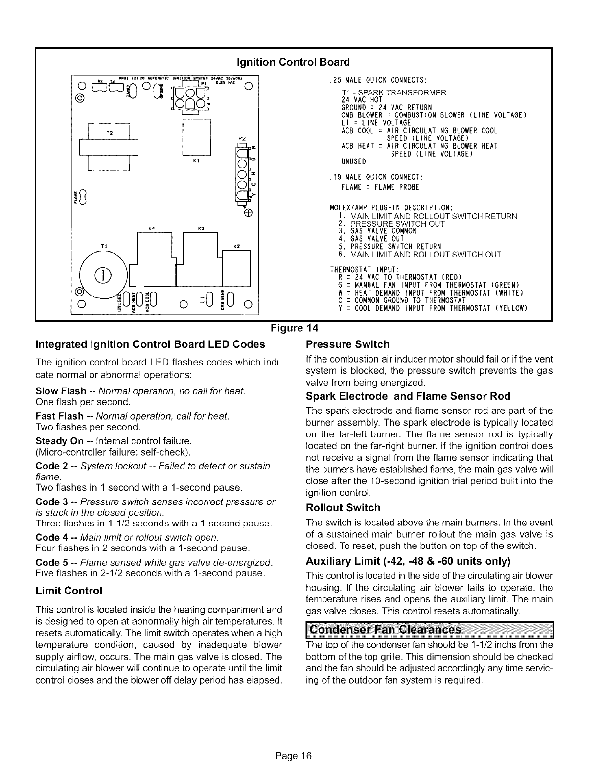
Integrated Ignition Control Board (A3)
The 13GCSX unit includes an integrated ignition control
board which controls the combustion air inducer, gas valve,
spark electrode and indoor blower. The control board
receives signals from the main and auxiliary limit switches,
the rollout switch, the pressure switch and the flame
sensor. LED codes and flash rates are given on page 16.
The ignition control board is shown in figure 14.
Page 15
Ignition Control Board
ANSl Z2t+20 mUtOrl_++=_: ImmltlOm mVSt[# 2+W*C SO/++Ol++
o @@8 ol3 .......o
@
+sL_ _1 *'
G
K4 K3
.25 MALE QUICK CONNECTS:
TI- SPARK TRANSFORMER
24 VAC HOT
GROUND : 24 VAC RETURN
CMB BLOWER : COMBUSTION BLOWER (LINE VOLTAGE)
LI : LINE VOLTAGE
ACB COOL : AIR CIRCULATING BLOWER COOL
SPEED (LINE VOLTAGE)
ACB HEAT : AIR CIRCULATING BLOWER HEAT
SPEED (LINE VOLTAGE)
UNUSED
,19 MALE QUICK CONNECT:
FLAME z FLAME PROBE
MOLEXIAMP PLUG-IN DESCRIPTION:
I. MAIN LIMIT AND ROLLOUT SWITCH RETURN
2, PRESSURE SWITCH OUT
3. GAS VALVE COMMON
4. GAS VALVE OUT
5. PRESSURE SWITCH RETURN
6, MAIN LIMIT AND ROLLOUT SWITCH OUT
THERMOSTAT INPUT:
R : 24 VAC TO THERMOSTAT (RED)
G : MANUAL FAN INPUT FROM THERMOSTAT (GREEN)
W : HEAT DEMAND INPUT FROM THERMOSTAT (WHITE)
C : COMMON GROUND TO THERMOSTAT
Y : COOL DEMAND INPUT FROM THERMOSTAT (YELLOW)
Figure
Integrated Ignition Control Board LED Codes
The ignition control board LED flashes codes which indi-
cate normal or abnormal operations:
Slow Flash -- Normal operation, no call for heat.
One flash per second,
Fast Flash -- Normal operation, call for heat,
Two flashes per second.
Steady On -- Internal control failure,
(Micro-controller failure; self-check),
Code 2 -- System lockout -- Failed to detect or sustain
flame,
Two flashes in 1 second with a 1-second pause.
Code 3 -- Pressure switch senses incorrect pressure or
is stuck in the closed position,
Three flashes in 1-1/2 seconds with a 1-second pause.
Code 4 -- Main limit or rollout switch open.
Four flashes in 2 seconds with a 1-second pause.
Code 5 -- Flame sensed while gas valve de-energized,
Five flashes in 2-1/2 seconds with a 1-second pause,
Limit Control
This control is located inside the heating compartment and
is designed to open at abnormally high air temperatures. It
resets automatically. The limit switch operates when a high
temperature condition, caused by inadequate blower
supply airflow, occurs. The main gas valve is closed. The
circulating air blower will continue to operate until the limit
control closes and the blower off delay period has elapsed.
14
Pressure Switch
If the combustion air inducer motor should fail or if the vent
system is blocked, the pressure switch prevents the gas
valve from being energized,
Spark Electrode and Flame Sensor Rod
The spark electrode and flame sensor rod are part of the
burner assembly. The spark electrode is typically located
on the far-left burner. The flame sensor rod is typically
located on the far-right burner. If the ignition control does
not receive a signal from the flame sensor indicating that
the burners have established flame, the main gas valve will
close after the 10-second ignition trial period built into the
ignition control.
Rollout Switch
The switch is located above the main burners. In the event
of a sustained main burner rollout the main gas valve is
closed. To reset, push the button on top of the switch,
Auxiliary Limit (-42, -48 & -60 units only)
This control is located in the side of the circulating air blower
housing. If the circulating air blower fails to operate, the
temperature rises and opens the auxiliary limit. The main
gas valve closes, This control resets automatically.
The top of the condenser fan should be 1-1/2 inchs from the
bottom of the top grille. This dimension should be checked
and the fan should be adjusted accordingly any time servic-
ing of the outdoor fan system is required.
Page 16
Periodicinspectionandmaintenancenormallyconsistsof
changingorcleaningfiltersand(undersomeconditions)
cleaningthemainburners,
Filters
Notsupplied.Inspectoncea month,Replacedisposableor
cleanpermanenttypeasnecessary,DONOTreplaceper-
manenttypewithdisposable,
Motors
Indoor,outdoorfan and ventmotorsare permanently
lubricatedand requireno furtherlubrication.Motors
shouldbecleanedyearlyto preventtheaccumulationof
dustanddirtonthewindingsormotorexterior,
Coil
Dirtanddebrisshouldnotbeallowedtoaccumulateonthe
coilsurfacesor otherpartsintheairconditioningcircuit.
Cleaningshouldbeperformedasoftenasnecessary.Use
a brush,vacuumcleanerattachment,or othersuitable
means,Ifwaterisusedtocleanthecoil,besurethepower
tounitisshutoffpriortocleaning.
NQ TE -Care should be used when cleaning the coil so that
the coil fins are not damaged.
Do not permit the hot condenser air discharge to be ob-
structed by overhanging structures or shrubs,
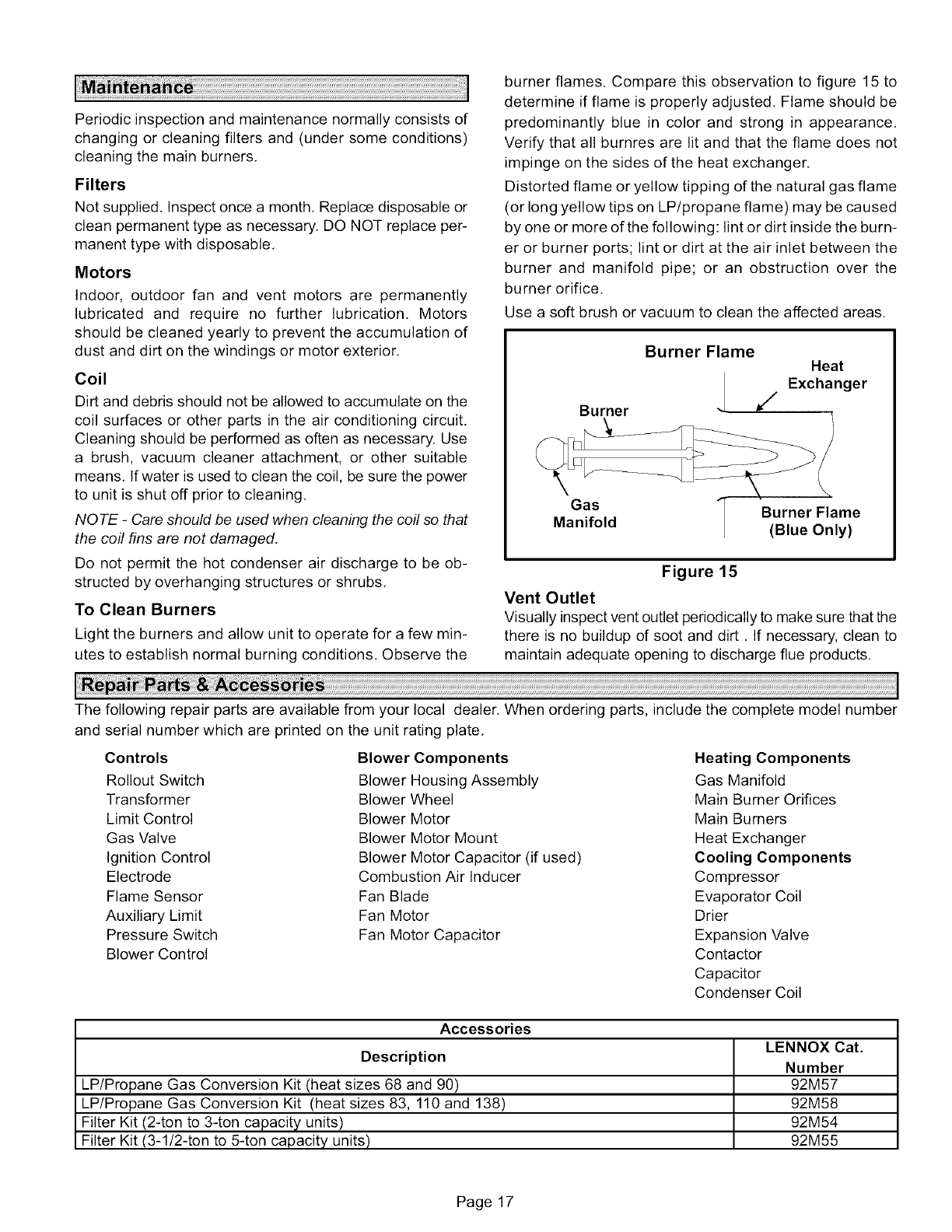
To Clean Burners
Light the burners and allow unit to operate for a few min-
utes to establish normal burning conditions, Observe the
burner flames. Compare this observation to figure 15 to
determine if flame is properly adjusted. Flame should be
predominantly blue in color and strong in appearance,
Verify that all burnres are lit and that the flame does not
impinge on the sides of the heat exchanger.
Distorted flame or yellow tipping of the natural gas flame
(or long yellow tips on LP/propane flame) may be caused
by one or more of the following: lint or dirt inside the burn-
er or burner ports; lint or dirt at the air inlet between the
burner and manifold pipe; or an obstruction over the
burner orifice.
Use a soft brush or vacuum to clean the affected areas,
Burner
Burner Flame Heat
Exchanger
/
Gas Burner Flame
Manifold (Blue Only)
Figure 15
Vent Outlet
Visually inspect vent outlet periodically to make sure that the
there is no buildup of soot and dirt. If necessary, clean to
maintain adequate opening to discharge flue products,
The following repair parts are available from your local dealer, When ordering parts, include the complete model number
and serial number which are printed on the unit rating plate,
Controls
Rollout Switch
Transformer
Limit Control
Gas Valve
Ignition Control
Electrode
Flame Sensor
Auxiliary Limit
Pressure Switch
Blower Control
Blower Components
Blower Housing Assembly
Blower Wheel
Blower Motor
Blower Motor Mount
Blower Motor Capacitor (if used)
Combustion Air Inducer
Fan Blade
Fan Motor
Fan Motor Capacitor
Heating Components
Gas Manifold
Main Burner Orifices
Main Burners
Heat Exchanger
Cooling Components
Compressor
Evaporator Coil
Drier
Expansion Valve
Contactor
Capacitor
Condenser Coil
Accessories
LENNOX Cat.
Number
92M57
92M58
92M54
92M55
Description
LP/Propane Gas Conversion Kit (heat sizes 68 and 90)
LP/Propane Gas Conversion Kit (heat sizes 83, 110 and 138)
Filter Kit (2-ton to 3-ton capacity units)
Filter Kit (3-1/2-ton to 5-ton capacity units)
Page 17
