LENNOX Package Units(both Units Combined) Manual L0806701
User Manual: LENNOX LENNOX Package Units(both units combined) Manual LENNOX Package Units(both units combined) Owner's Manual, LENNOX Package Units(both units combined) installation guides
Open the PDF directly: View PDF ![]() .
.
Page Count: 6
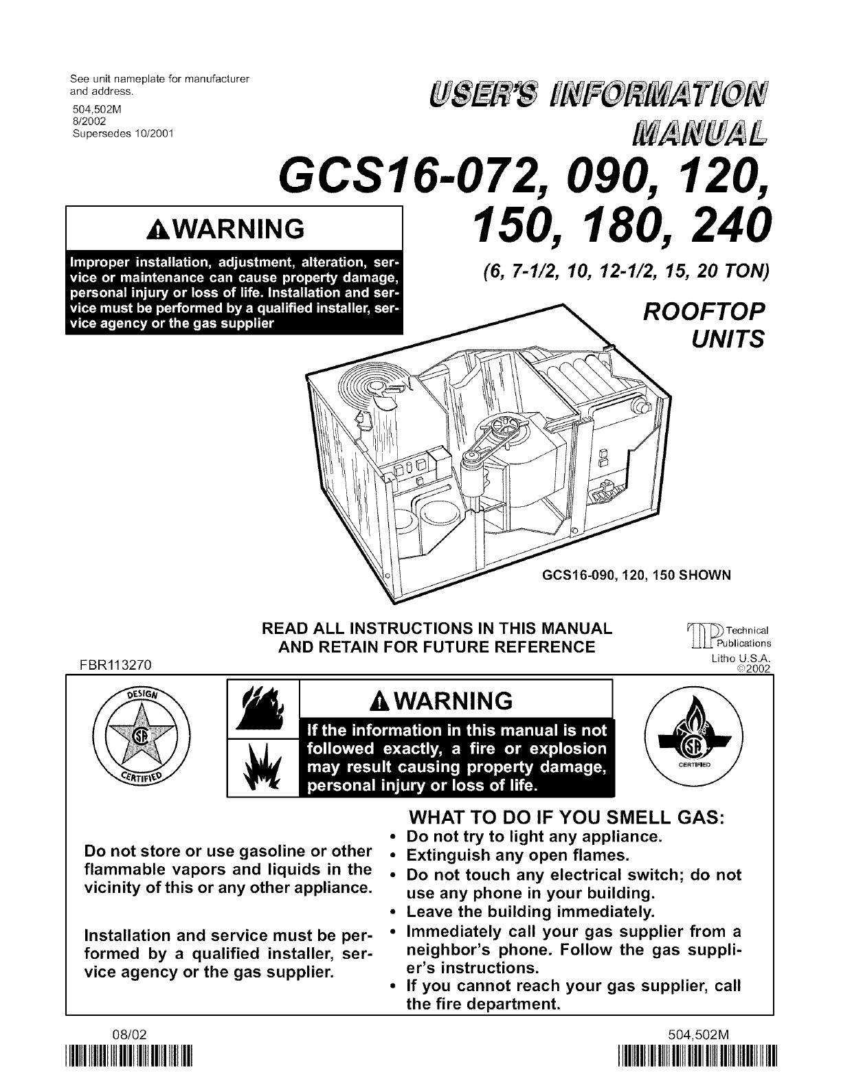
See unit nameplate for manufacturer
and address.
504,502M
8/2002
Supersedes 10/2001
GCS16-072, 090,
AWARNING 150, 180,
(6, 7-1/2, 10, 12-1/2, 15, 20 TON)
ROOFTOP
UNITS
GCS16-090, 120, 150 SHOWN
FBR113270
READ ALL INSTRUCTIONS IN THIS MANUAL
AND RETAIN FOR FUTURE REFERENCE
-&WARNING
TeChnical
blications
Lithe U.S.A.
G_)2002
Do not store or use gasoline or other
flammable vapors and liquids in the
vicinity of this or any other appliance.
Installation and service must be per-
formed by a qualified installer, ser-
vice agency or the gas supplier.
WHAT TO DO IF YOU SMELL GAS:
•Do not try to light any appliance.
•Extinguish any open flames.
•Do not touch any electrical switch; do not
use any phone in your building.
•Leave the building immediately.
•Immediately call your gas supplier from a
neighbor's phone. Follow the gas suppli-
er's instructions.
•If you cannot reach your gas supplier, call
the fire department.
08/02
IIIIIIIIIIIIIIIIIIIIIIIIIIIIIIIIIIIIIIll 504,502M
IIIllllllllllllllllllllllllllHIIIIIIIIlllll
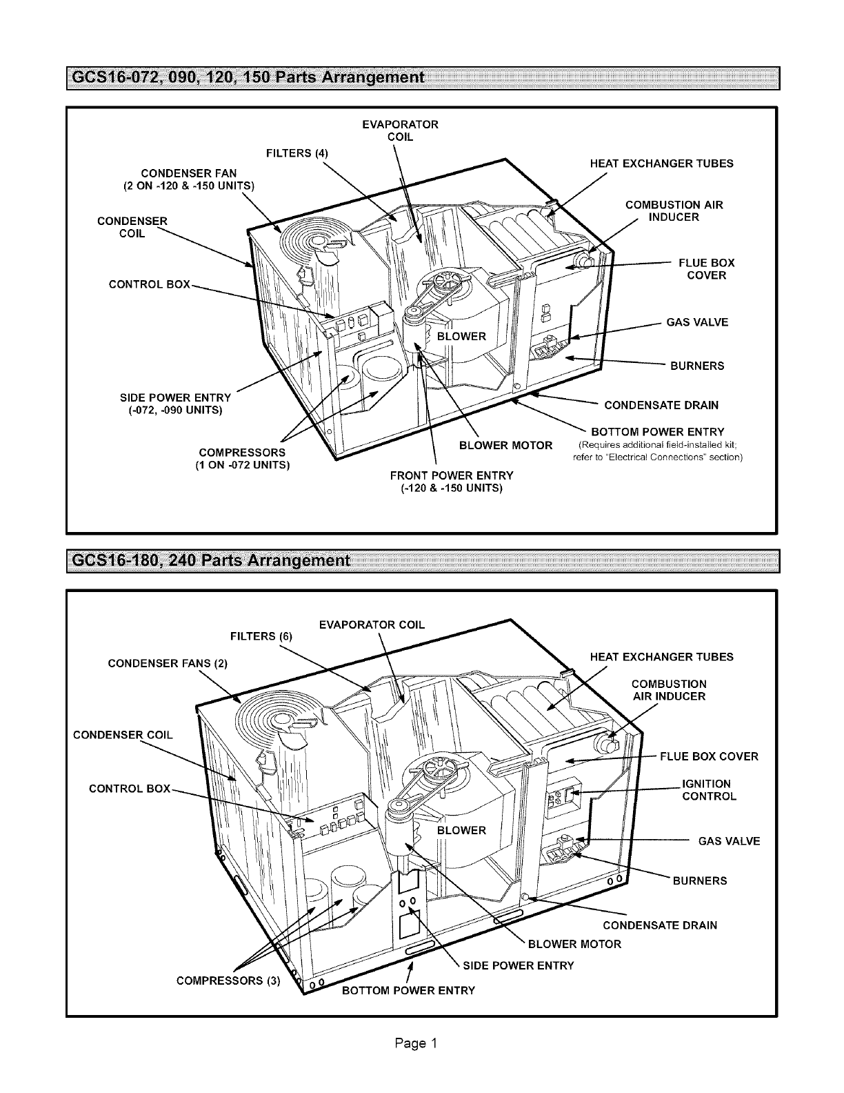
CONDENSER FAN
(2 ON -120 &-150 UNITS)
CONDENSER
COIL
CONTROLBOX_
SIDE POWER ENTRY
(-072, -090 UNITS)
COMPRESSORS
(10N-072UNITS)
FILTERS (4)
EVAPORATOR
COIL
HEAT EXCHANGERTUBES
COMBUSTION AIR
INDUCER
FLUE BOX
COVER
GAS VALVE
BURNERS
CONDENSATE DRAIN
BOTTOM POWER ENTRY
BLOWER MOTOR (Requires additionalfield-installed kit;
refer to "Electrical Connections" section)
FRONT POWER ENTRY
(-120 & -150 UNITS)
EVAPORATOR COIL
FILTERS (6)
CONDENSER FANS (2) HEAT EXCHANGERTUBES
COMBUSTION
AIRINDUCER
CONDENSER COIL
CONTROL
COVER
IGNITION
CONTROL
GAS VALVE
COMPRESSORS(3) BOTTOM POWER ENTRY
CONDENSATE DRAIN
BLOWER MOTOR
POWER ENTRY
Page 1
, ,WARNING
,&,WARNING
-
.
-
-
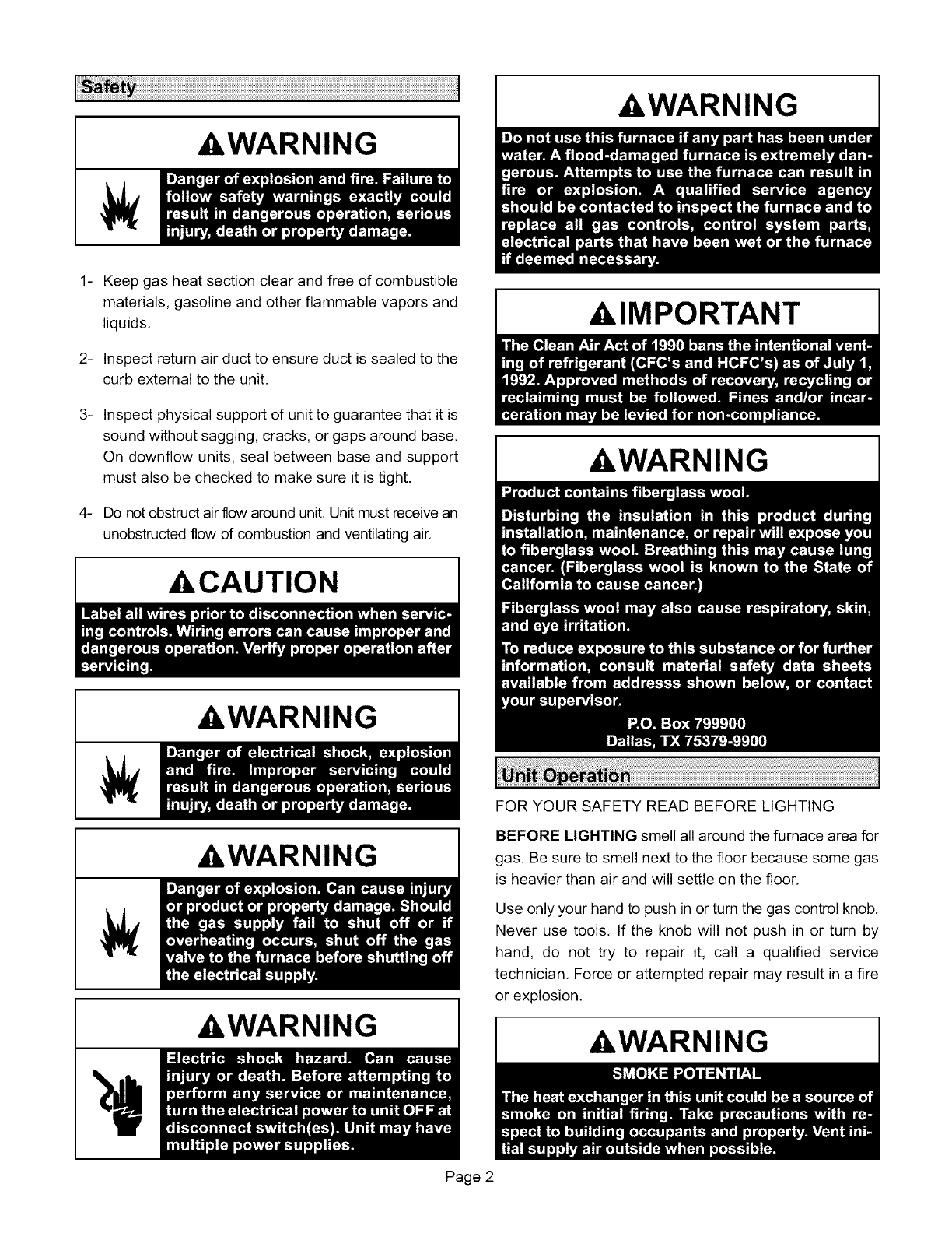
Keep gas heat section clear and free of combustible
materials, gasoline and other flammable vapors and
liquids,
Inspect return air duct to ensure duct is sealed to the
curb external to the unit,
Inspect physical support of unit to guarantee that it is
sound without sagging, cracks, or gaps around base,
On downflow units, seal between base and support
must also be checked to make sure it is tight,
Do not obstruct air flow around unit, Unit must receive an
unobstructed flow of combustion and ventilating air.
,&,CAUTION
,&WARNING
,&WARNING
,&WARNING
,&IMPORTANT
A,WARNING
FOR YOUR SAFETY READ BEFORE LIGHTING
BEFORE LIGHTING smell all around the furnace area for
gas. Be sure to smell next to the floor because some gas
is heavier than air and will settle on the floor,
Use only your hand to push in or turn the gas control knob.
Never use tools. If the knob will not push in or turn by
hand, do not try to repair it, call a qualified service
technician. Force or attempted repair may result in a fire
or explosion.
,&,WARNING
Page 2
,WARNING
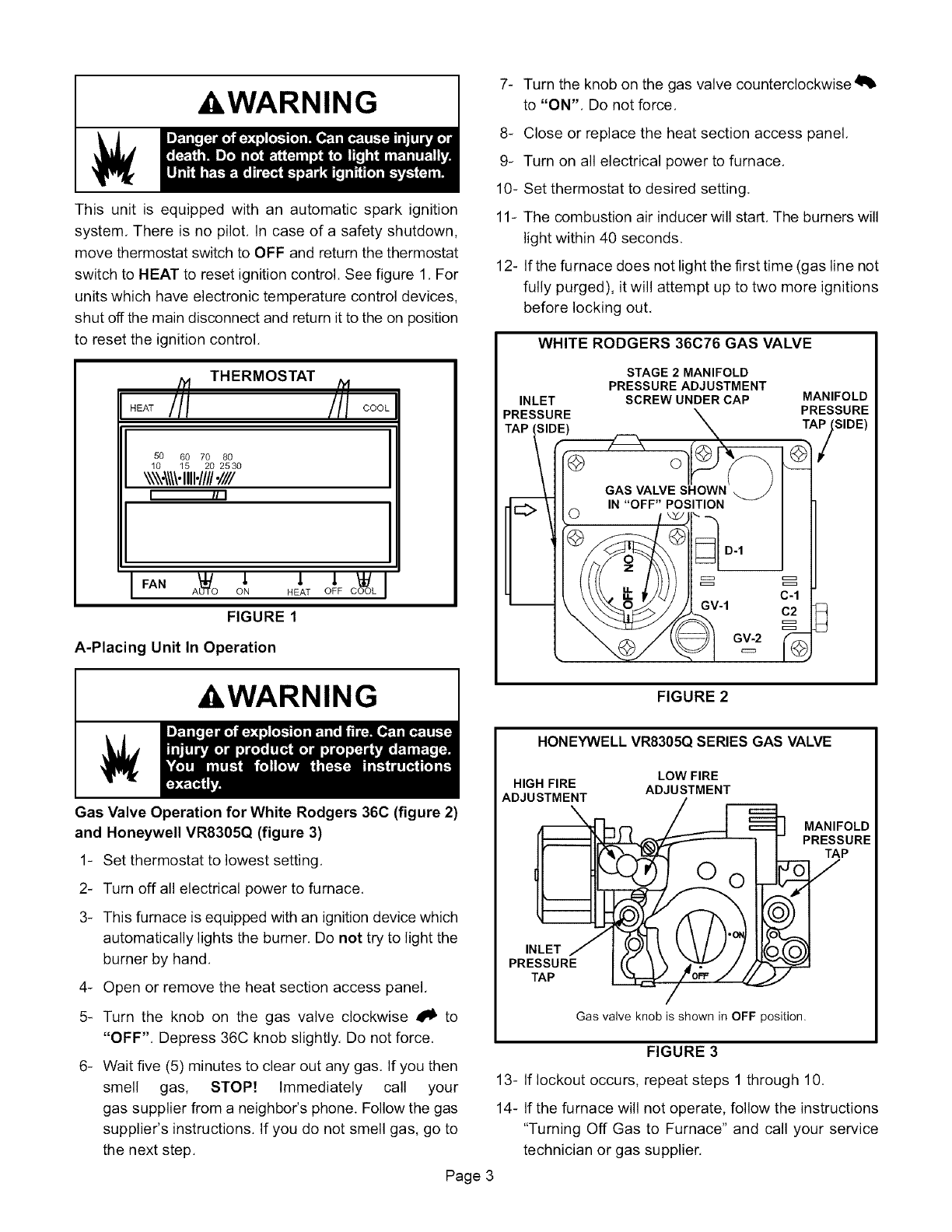
This unit is equipped with an automatic spark ignition
system. There is no pilot. In case of a safety shutdown,
move thermostat switch to OFF and return the thermostat
switch to HEAT to reset ignition control. See figure 1. For
units which have electronic temperature control devices,
shut off the main disconnect and return it to the on position
to reset the ignition control.
/_ THERMOSTAT .
HEAT I!! lil COOL
50 60 70 80
10 15 20 2530
\\\\'_\\\"III1"////'1111
III I
IFAN ON HEAT OFF COOL
FIGURE 1
A-Placing Unit In Operation
,WARNING
Gas Valve Operation for White Rodgers 36C (figure 2)
and Honeywell VR8305Q (figure 3)
1- Set thermostat to lowest setting.
2- Turn off all electrical power to furnace.
3- This furnace is equipped with an ignition device which
automatically lights the burner. Do not try to light the
burner by hand.
4- Open or remove the heat section access panel.
5- Turn the knob on the gas valve clockwise 4_ to
"OFF". Depress 36C knob slightly. Do not force.
6- Wait five (5) minutes to clear out any gas. If you then
smell gas, STOP! Immediately call your
gas supplier from a neighbor's phone. Follow the gas
supplier's instructions. If you do not smell gas, go to
the next step.
7- Turn the knob on the gas valve counterclockwise41_
to "ON". Do not force.
8- Close or replace the heat section access panel.
9- Turn on all electrical power to furnace.
10- Set thermostat to desired setting.
11- The combustion air inducer will start. The burners will
light within 40 seconds.
12- If the furnace does not light the first time (gas line not
fully purged), it will attempt up to two more ignitions
before locking out.
WHITE RODGERS 36C76 GAS VALVE
INLET
PRESSURE
STAGE2 MANIFOLD
PRESSURE ADJUSTMENT
SCREW UNDER CAP MANIFOLD
PRESSURE
TAP_SIDE)
FIGURE 2
HONEYWELL VR8305Q SERIES GAS VALVE
LOW FIRE
HIGH FIRE ADJUSTMENT
ADJUSTMENT
,
PRESSURE I(( _ _ 4'''_t_" ,
TAP L._._=Vi oF_/
Gas valve knob is shown in OFF position,
MANIFOLD
PRESSURE
TAP
FIGURE 3
13- If lockout occurs, repeat steps 1 through 10.
14- If the furnace will not operate, follow the instructions
"Turning Off Gas to Furnace" and call your service
technician or gas supplier.
Page 3
Turning Off Gas to Furnace
-
2-
If using an electromechanical thermostat, set to the
lowest setting.
Before performing any service, turn off all electrical
power to the furnace.
&CAUTION
3- Open or remove the heat section access panel.
4- Turn the knob on the gas valve clockwise _1_ to
"OFF". Depress 36C knob slightly. Do not force.
5- Replace heat section access panel.
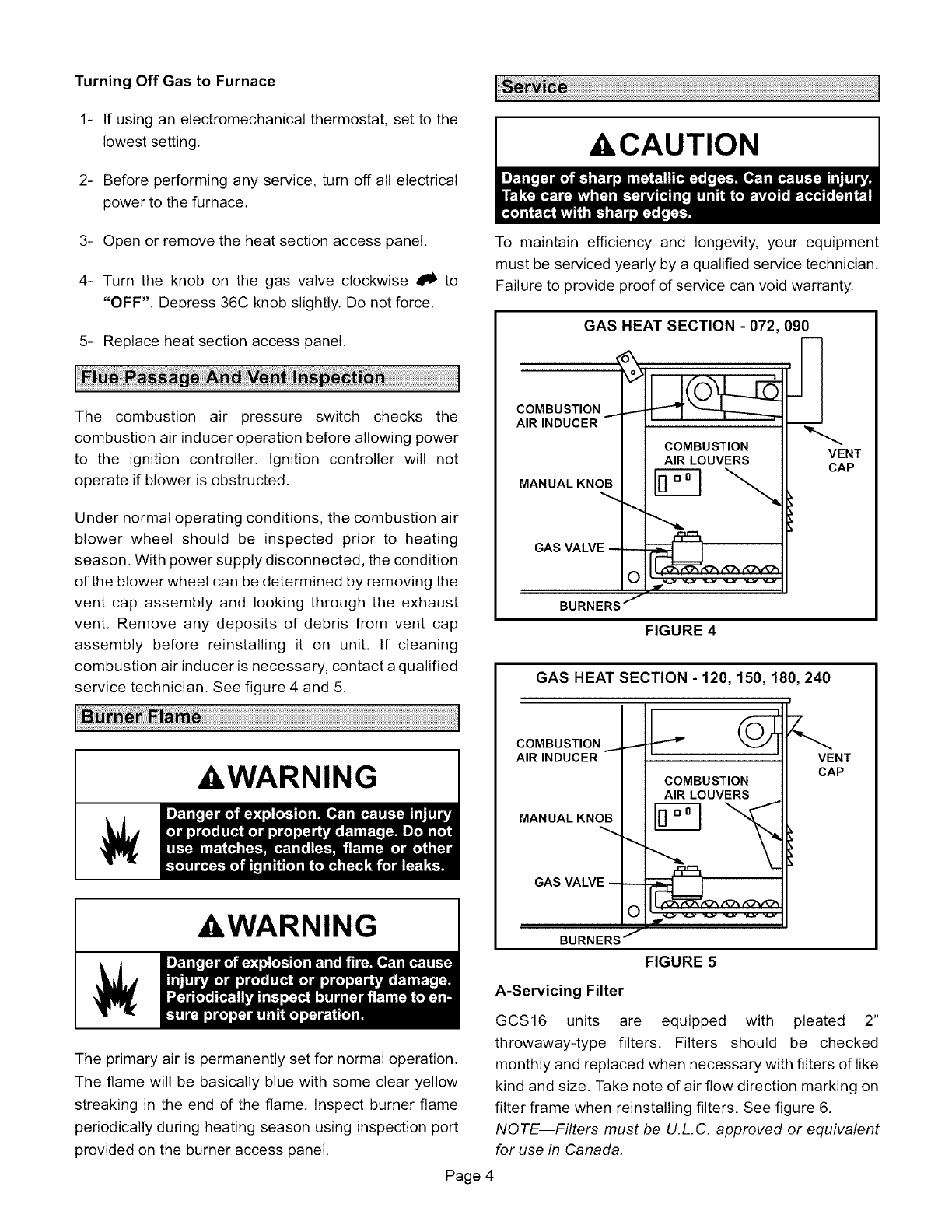
The combustion air pressure switch checks the
combustion air inducer operation before allowing power
to the ignition controller. Ignition controller will not
operate if blower is obstructed.
Under normal operating conditions, the combustion air
blower wheel should be inspected prior to heating
season. With power supply disconnected, the condition
of the blower wheel can be determined by removing the
vent cap assembly and looking through the exhaust
vent. Remove any deposits of debris from vent cap
assembly before reinstalling it on unit. If cleaning
combustion air inducer is necessary, contact a qualified
service technician. See figure 4 and 5.
&WARNING
&WARNING
The primary air is permanently set for normal operation.
The flame will be basically blue with some clear yellow
streaking in the end of the flame. Inspect burner flame
periodically during heating season using inspection port
provided on the burner access panel.
To maintain efficiency and longevity, your equipment
must be serviced yearly by a qualified service technician.
Failure to provide proof of service can void warranty.
GAS HEAT SECTION - 072,090
._OMBUSTION _--
_,IR INDUCER
MANUALKNOB
GAS VALVE --_
O
BURNERS /
COMBUSTION
AIR LOUVERS VENT
CAP
FIGURE 4
GAS HEAT SECTION - 120, 150, 180, 240
;OMBUSTION .
_IRINDUCER
MANUALKNOB
GAS VALVE --_
O
BURNERS _
COMBUSTION
AIR LOUVERS
I
VENT
CAP
FIGURE 5
A-Servicing Filter
GCS16 units are equipped with pleated 2"
throwaway-type filters, Filters should be checked
monthly and replaced when necessary with filters of like
kind and size. Take note of air flow direction marking on
filter frame when reinstalling filters. See figure 6,
NOTE--Filters must be U.L,C, approved or equivalent
for use in Canada,
Page 4
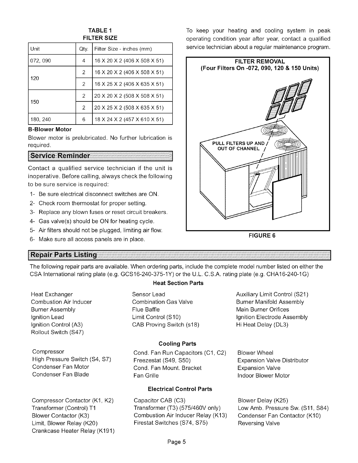
TABLE 1
FILTER SIZE
Unit Qty.
072, 090 4
2
120
2
2
150
2
180, 240 6
B-Blower Motor
Filter Size - inches (mm)
16 X 20 X 2 (406 X 508 X 51)
16 X 20 X 2 (406 X 508 X 51)
16 X 25 X 2 (406 X 635 X 51)
20 X 20 X 2 (508 X 508 X 51)
20 X 25 X 2 (508 X 635 X 51)
18 X 24 X 2 (457 X 610 X 51)
Blower motor is prelubricated. No further lubrication is
required.
Contact a qualified service technician if the unit is
inoperative. Before calling, always check the following
to be sure service is required:
1- Be sure electrical disconnect switches are ON.
2- Check room thermostat for proper setting.
3- Replace any blown fuses or reset circuit breakers.
4- Gas valve(s) should be ON for heating cycle.
5- Air filters should not be plugged, limiting air flow.
6- Make sure all access panels are in place.
To keep your heating and cooling system in peak
operating condition year after year, contact a qualified
service technician about a regular maintenance program.
FILTER REMOVAL
(Four Filters On -072, 090, 120 & 150 Units)
FIGURE 6
The following repair parts are available. When ordering parts, include the complete model number listed on either the
CSA International rating plate (e.g. GCS16-240-375-1Y) or the U.L.C.S.A. rating plate (e.g. CHA16-240-1 G)
Heat Section Parts
Heat Exchanger
Combustion Air Inducer
Burner Assembly
Ignition Lead
Ignition Control (A3)
Rollout Switch (S47)
Compressor
High Pressure Switch (S4, S7)
Condenser Fan Motor
Condenser Fan Blade
Sensor Lead
Combination Gas Valve
Flue Baffle
Limit Control (S 10)
CAB Proving Switch (s18)
Cooling Parts
Cond, Fan Run Capacitors (C1, C2)
Freezestat (S49, S50)
Cond, Fan Mount, Bracket
Fan Grille
Auxiliary Limit Control (S21)
Burner Manifold Assembly
Main Burner Orifices
Ignition Electrode Assembly
Hi Heat Delay (DL3)
Blower Wheel
Expansion Valve Distributor
Expansion Valve
Indoor Blower Motor
Compressor Contactor (K1, K2)
Transformer (Control) T1
Blower Contactor (K3)
Limit, Blower Relay (K20)
Crankcase Heater Relay (K191)
Electrical Control Parts
Capacitor CAB (C3)
Transformer (T3) (575/460V only)
Combustion Air Inducer Relay (K13)
Firestat Switches (S74, S75)
Blower Delay (K25)
Low Amb. Pressure Sw. (S11, S84)
Condenser Fan Contactor (K10)
Reversing Valve
Page 5
