LENNOX Package Units(both Units Combined) Manual L0806704
User Manual: LENNOX LENNOX Package Units(both units combined) Manual LENNOX Package Units(both units combined) Owner's Manual, LENNOX Package Units(both units combined) installation guides
Open the PDF directly: View PDF ![]() .
.
Page Count: 8

See unit nameplate for manufacturer
and address.
504,875M
1/2006
Supersedes 1/2004
LGA/LGC036, 042, 048, 060, 072
(3, 3-1/2, 4, 5, and 6 TONS)
LGA/LGC090, 102, 120, 150,
(7-1/2, 8-1/2, 10, and 12-1/2 TONS)
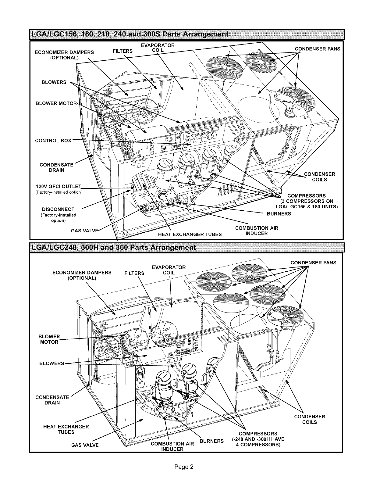
LGA/LGC156, 180, 210, 240, 300S
(13, 15, 17-1/2, 20, and 25 TONS)
LGA/LGC248, 30OH, 360
(20, 25, and 30 TONS)
ROOFTOP
UNITS
FBR113270
LGA240 SHOWN
READ ALL INSTRUCTIONS IN THIS MANUAL
AND RETAIN FOR FUTURE REFERENCE
_pu Technical
blications
Litho U.S.A.
@2006
A\tL't F-,R_*_A
C US
/-18TEO
jA WARNING
Do not store or use gasoline or other
flammable vapors and liquids in the
vicinity of this or any other appliance.
Installation and service must be per-
formed by a qualified installer, ser-
vice agency or the gas supplier.
01/06
IIIIIIIIIIIIIIIIIIIIIIIIIIIIIIIIIIIIIIII
WHAT TO DO IF YOU SMELL GAS:
• Do not try to light any appliance.
•Extinguish any open flames.
•Do not touch any electrical switch; do not
use any phone in your building.
•Leave the building immediately.
•Immediately call your gas supplier from a
neighbor's phone. Follow the gas suppli-
er's instructions.
•If you cannot reach your gas supplier, call
the fire department. 504,875M
IIIHIIIII11111IIIIIIIIII11111111111111111IIIIII
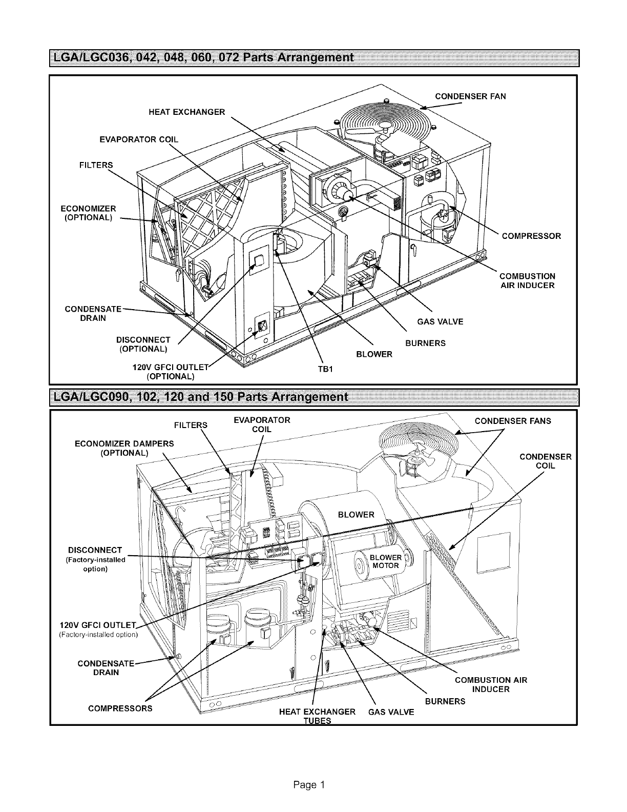
HEAT EXCHANGER
CONDENSER FAN
EVAPORATOR COIL
FILTERS
ECONOMIZER
(OPTIONAL)
COMPRESSOR
COMBUSTION
AIRINDUCER
DRAIN GAS VALVE
DISCONNECT BURNERS
(OPTIONAL) BLOWER
120V TB1
(OPTIONAL)
ECONOMIZER DAMPERS
(OPTIONAL) CONDENSER
COIL
DISCONNECT
(Factory-installed
option)
(Factory-installed option)
DRAIN
COMPRESSORS HEAT EXCHANGER GAS VALVE
TUBES
COMBUSTION AIR
INDUCER
BURNERS
Page 1
BLOWERS
BLOWER MOTOR,
CONTROL
CONDENSATE
DRAIN
120V GFCI OUTLET
(Factory-installed option)
DISCONNECT
(Factory=installed
option)
HEAT EXCHANGER TUBES
CONDENSER
COILS
COMPRESSORS
(3COMPRESSORS ON
LG_LGC156&180UNITS)
BURNERS
COMBUSTION AIR
INDUCER
ECONOMIZER DAMPERS
(OPTIONAL)
EVAPORATOR
FILTERS COIL
CONDENSER FANS
BLOWER
MOTOR
CONDENSATE
DRAIN
HEAT EXCHANGER
TUBES
GAS VALVE COMBUSTION AIR
INDUCER
BURNERS
COMPRESSORS
(-248 AND -300H HAVE
4COMPRESSORS)
CONDENSER
COILS
Page 2
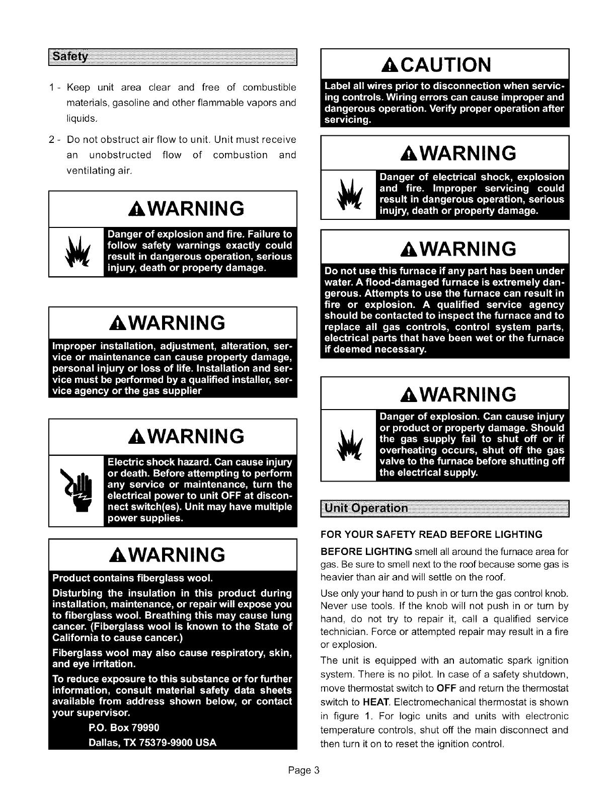
1- Keep unit area clear and free of combustible
materials,gasolineandotherflammablevaporsand
liquids,
2 - Donotobstructairflowto unit,Unitmustreceive
an unobstructed flow of combustion and
ventilatingair,
`&WARNING
`&WARNING
`&WARNING
AWARNING
,&CAUTION
,&WARNING
,&WARNING
,&WARNING
FOR YOUR SAFETY READ BEFORE LIGHTING
BEFORE LIGHTING smell all around the furnace area for
gas. Be sure to smell next to the roof because some gas is
heavier than air and will settle on the roof,
Use only your hand to push in or turn the gas control knob,
Never use tools, If the knob will not push in or turn by
hand, do not try to repair it, call a qualified service
technician. Force or attempted repair may result in a fire
or explosion,
The unit is equipped with an automatic spark ignition
system, There is no pilot, In case of a safety shutdown,
move thermostat switch to OFF and return the thermostat
switch to HEAT, Electromechanical thermostat is shown
in figure 1. For logic units and units with electronic
temperature controls, shut off the main disconnect and
then turn it on to reset the ignition control,
Page 3

TYPICAL ELECTROMECHANICAL THERMOSTAT
-//I //I
50 60 70 80 g0
10 15 20 25 80
\\\\'\/\/"IIII"11II"////
i !!I
ON HEAT OFF COOL
FIGURE 1
Placing Unit Into Operation
,&WARNING
Gas Valve Operation for White Rodgers 36C (figure 4),
White Rodgers 36E (figure 2), Honeywell VR8205M
(figure 3), and Honeywell VR8205QNR8305Q (figure 5)
1- Set thermostat to lowest setting,
2- Turn off all electrical power to furnace,
3- This furnace is equipped with an ignition device which
automatically lights the burner, Do not try to light the
burner by hand,
4- Open or remove the heat section access panel,
5- 36C, VR8205, & VR8305-
Turn the knob on the gas valve clockwise _1_ to
"OFF", Depress 36C knob slightly, Do not force,
36E -
Turn the knob 180° either way to "OFF",
WHITE RODGERS 36E GAS VALVE
INLET
PRESSURE
TAP (SIDE)
8
\
Gas valve knob is shown
in OFF position.
-1
MANIFOLD
PRESSURE
TAP (SIDE)
FIGURE 2
I HONEYWELL VR8205M SERIES GAS VALVE
I INLET _ :::::::::::_T"_ MANIFOLD
,, _PRESTASURE
FIGURE 3
WHITE RODGERS 36C76 GAS VALVE
STAGE 2 MANUAL MANIFOLD MANIFOLD
INLET PRESSURE ADJUSTMENT PRESSURE
PRESSURE SCREW UNDER CAP TAP ;SIDE)
FIGURE 4-- --
HONEYWELL VR8205_ SE_S G"ASVALVE 1
HIGH FIRE LOW FIRE /
ADJ__ ADJ_;÷__ MAN,FOLD/
r,,PRESSURE/
/
Gas valve knob is shown in OFF position. /
FIGURE 5
6- Wait five (5) minutes to clear out any gas, If you then
smell gas, STOP! Immediately call your
gas supplier from a neighbor's phone, Follow the gas
supplier's instructions, If you do not smell gas, go to
the next step.
7- 36C, VR8205, & 8305 -
Turn the knob on the gas valve counterclockwise 41_
to "ON", Do not force,
36E -
Turn the knob 180 ° either way to "ON",
8- Close or replace the heat section access panel.
9- Turn on all electrical power to furnace,
10- Set thermostat to desired setting,
Page 4

11- Thecombustionair inducerwillstart,Theburners
willlightwithin40seconds,
12- Ifthefurnacedoesnotlightthefirsttime(gaslinenot
fullypurged),it willattemptuptotwomoreignitions
beforelockingout,
13- Iflockoutoccurs,repeatsteps1through10,
14- Ifthefurnacewillnotoperate,followtheinstructions
"TurningOffGasto Furnace"andcallyourservice
technicianorgassupplier.
TurningOffGasto Furnace
1- Ifusinganelectromechanicalthermostat,settothe
lowestsetting.
2- Beforeperforminganyservice,turnoffallelectrical
powerto thefurnace.
3- Openorremovetheheatsectionaccesspanel.
4- 36C, VR8205, & VR8305-
Turn the knob on the gas valve clockwise _ to
"OFF". Depress 36C knob slightly. Do not force.
36E -
Turn the knob 180° either way to "OFF".
5- Close or replace the heat section access panel.
A,WARNING
To maintain efficiency and longevity, your equipment
must be serviced yearly by a qualified service technician.
Failure to provide proof of service can void warranty.
A, CAUTION
HEAT EXCHANGER ASSEMBLY (036-072)
HEAT
EXCHANGER T
COMBUSTION
AIR
INDUCER
\
BAFFLE
FLUE BOX
GAS
VALVE VENT
CONNECTOR
FIGURE 6
HEAT EXCHANGER ASSEMBLY (090-360)
&WARNING
The primary air is permanently set for normal operation.
The flame will be basically blue with some clear yellow
streaking in the end dthe flame, Inspect the burner flame
periodically during the heating season using the
inspection port provided on the burner access panel.
Annually, before heating season, inspect the combustion
air louvers, vent cap, heat exchanger, burners and
combustion air inducer for corrosion, deterioration or
deposits of debris. Remove any obstructions or blockage.
See figures 6 and 7.
HEAT
EXCHANGER
TUBE
COMBUSTION
AIR
VENT
GAS VALVE
BURNER
FIGURE 7
Page 5

ServicingFilter
Unitsareequippedwiththe numberof filtersshownin
table1,Filtersshouldbecheckedmonthlyandreplaced
whennecessarywithfiltersoflikekindandsize.Takenote
of air flow directionmarkingon filter frame when
reinstallingfilters,Seefigure8,
REMOVE FILTERS
PULL TO REMOVE
FILTERS
FIGURE 8
NOTE -Filters must be ULC approved or equivalent for
use in Canada.
TABLE 1
NUMBER AND SIZE OF FILTER BY UNIT
LGA/LGC Unit
036, 042, 048,060,072
090,102,120,150
156,180,210,240,300S
248,300H, 360
Qty Filter Size - inches (mm)
2 16 X 25 X 2 (406 X 635 X 51)
4 18 X 24 X 2 (457 X 610 X 51)
6 24 X 24 X 2 (610 X 610 X 51)
12 20X20X2(508X508X51)
Lubrication
All motors are lubricated at the factory, No further
lubrication is required,
Blower shaft bearings are prelubricated, For extended
bearing life, relubricate at least once every two years
with a lithium base grease, such as AIvania 3 (Shell Oil),
Chevron BRB2 (Standard Oil) or Regal AFB2 (Texas
Oil). Use a hand grease gun for relubrication, Add only
enough grease to purge through the bearings so that a
bead of grease appears at the seal lip contacts.
Manifold Pressures
Manifold pressures are shown in table 2. Refer to figures
2, 3, 4 and 5 to locate pressure ports.
TABLE 2
MANIFOLD PRESSURES in.wg. (kPa)
Natural Gas Propane (LP) Gas
LGA/LGC Unit 1st Stg.+ 2nd Stg.+ 1st Stg.+ 2nd Stg.+
0.2(+.05) 0.3 (+.08) 0.2 (+.05) 0.3 (+.08)
036, 042, 048, 060, NA 3.5 NA 10.5
072 Std./High Heat (0.87) (2.61 )
036, 042, 048, 060, 1.9 3.5 5.3 10.5
072 Dual Heat (0.47) (0.87) (1.32) (2.61)
1.6 3.7 5.5 10.5
090 through 360 (0.40) (0.92) (1.37) (2.61)
Burners
Clean the burners as follows:
_
2-
3_
Turn off the electrical power and the gas supply to the
unit.
Open or remove the burner compartment access
panel,
Remove two screws securing burners to burner
support and lift the burners from the orifices. See
figure 9. Clean as necessary, Spark gap on ignition
electrode must be properly set, Refer to the Heating
Adjustment section in the installation instructions.
GAS
VALVE
BURNER BOX ASSEMBLY
!
GAS MANIFOLD
FLAME
SENSOR
FIGURE 9
Page 6
4-Replace burnersand screwssecuringburner,
Replacetheburnercompartmentaccesspanel,
5- Turnon the electrical power and the gas supply to the
unit, Follow the operating instructions attached to the
unit and use the inspection port in the access panel
to check the flame,
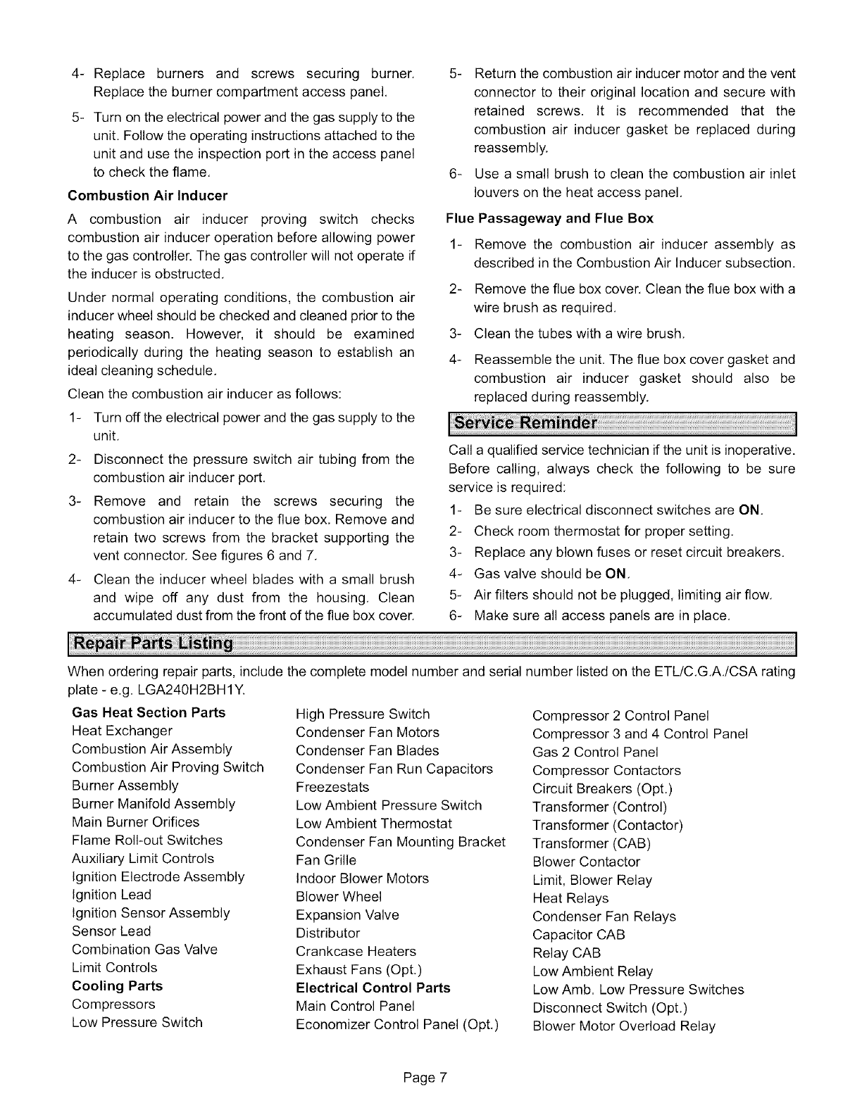
Combustion Air Inducer
A combustion air inducer proving switch checks
combustion air inducer operation before allowing power
to the gas controller. The gas controller will not operate if
the inducer is obstructed,
Under normal operating conditions, the combustion air
inducer wheel should be checked and cleaned prior to the
heating season. However, it should be examined
periodically during the heating season to establish an
ideal cleaning schedule,
Clean the combustion air inducer as follows:
1- Turn off the electrical power and the gas supply to the
unit,
2- Disconnect the pressure switch air tubing from the
combustion air inducer port,
3- Remove and retain the screws securing the
combustion air inducer to the flue box, Remove and
retain two screws from the bracket supporting the
vent connector. See figures 6 and 7,
4- Clean the inducer wheel blades with a small brush
and wipe off any dust from the housing, Clean
accumulated dust from the front of the flue box cover.
5- Return the combustion air inducer motor and the vent
connector to their original location and secure with
retained screws. It is recommended that the
combustion air inducer gasket be replaced during
reassembly.
6- Use a small brush to clean the combustion air inlet
louvers on the heat access panel,
Flue Passageway and Flue Box
1- Remove the combustion air inducer assembly as
described in the Combustion Air Inducer subsection,
2- Remove the flue box cover. Clean the flue box with a
wire brush as required,
3- Clean the tubes with a wire brush,
4- Reassemble the unit. The flue box cover gasket and
combustion air inducer gasket should also be
replaced during reassembly,
Call a qualified service technician if the unit is inoperative.
Before calling, always check the following to be sure
service is required:
1- Be sure electrical disconnect switches are ON,
2- Check room thermostat for proper setting,
3- Replace any blown fuses or reset circuit breakers,
4- Gas valve should be ON,
5- Air filters should not be plugged, limiting air flow,
6- Make sure all access panels are in place,
When ordering repair parts, include the complete model number and serial number listed on the ETL/C,G,A,/CSA rating
plate - e.g. LGA240H2BH 1Y.
Gas Heat Section Parts
Heat Exchanger
Combustion Air Assembly
Combustion Air Proving Switch
Burner Assembly
Burner Manifold Assembly
Main Burner Orifices
Flame Roll-out Switches
Auxiliary Limit Controls
Ignition Electrode Assembly
Ignition Lead
Ignition Sensor Assembly
Sensor Lead
Combination Gas Valve
Limit Controls
Cooling Parts
Compressors
Low Pressure Switch
High Pressure Switch
Condenser Fan Motors
Condenser Fan Blades
Condenser Fan Run Capacitors
Freezestats
Low Ambient Pressure Switch
Low Ambient Thermostat
Condenser Fan Mounting Bracket
Fan Grille
Indoor Blower Motors
Blower Wheel
Expansion Valve
Distributor
Crankcase Heaters
Exhaust Fans (Opt.)
Electrical Control Parts
Main Control Panel
Economizer Control Panel (Opt,)
Compressor 2 Control Panel
Compressor 3 and 4 Control Panel
Gas 2 Control Panel
Compressor Contactors
Circuit Breakers (Opt.)
Transformer (Control)
Transformer (Contactor)
Transformer (CAB)
Blower Contactor
Limit, Blower Relay
Heat Relays
Condenser Fan Relays
Capacitor CAB
Relay CAB
Low Ambient Relay
Low Amb. Low Pressure Switches
Disconnect Switch (Opt,)
Blower Motor Overload Relay
Page 7
