LENNOX Furnace/Heater, Gas Manual L0806816
User Manual: LENNOX LENNOX Furnace/Heater, Gas Manual LENNOX Furnace/Heater, Gas Owner's Manual, LENNOX Furnace/Heater, Gas installation guides
Open the PDF directly: View PDF ![]() .
.
Page Count: 4

GAS UNITS
KITS AND ACCESSORIES Litho U.S.A.
@1997LennoxIndustriesInc. 503,667M
Dallas,Texas 7/97
Supersedes 502,850M
HEAT EXCHANGER AND GAS
VALVE/IGNITION CONTROL
REPLACEMENT KIT
INSTALLATION INSTRUCTIONS FOR HEAT EXCHANGER AND GAS VALVE/IGNITION
CONTROL REPLACEMENT KIT (26Jg001PR)
USED WITH G20 SERIES FURNACES WITH STANDING PILOT IGNITION
Package I of I contains:
1 - Heat exchanger
3- Strip of insulation
1 - Draft hood Gasket
1 - Metal strip
1 - Warning sticker
1- Wiring harness
1 - Gas valve/ignition control replacement kit
20H77 (LB-62095BA)
1- Ignition control (Johnson)
1- Stand-off bracket
1- Gas valve (Honeywell)
1- Pilot burner assembly (includes sensor)
2- #8 - 32 X 3/4" thread-forming screws
2- #8 - 32 X 1/2" thread-forming screws
6- Wires
4- Wiring diagram sticker
Check all components for shipping damage. Consult
last carrier immediately if damage is found.
These instructions are intended as a general guide
and do not supersede local codes in any way.
Information regarding the installation of gas
valve/ignition control replacement kit 20H77, is
provided in these installation instructions. (Disregard
the Lennox installation instructions provided in kit
20H77).
This kit allows the changeover to electronic ignition
from standing pilot on G20 series units. The existing
heat exchanger and gas valve must be removed and
replaced. A gas valve replacement kit with electronic
ignition control and wiring harness is included to
complete the changeover. See table 1 for unit model
numbers and corresponding heat exchanger
replacement kits.
G20Q2-50
G20Q4E-75
Q20QS/6E-100
G20E-150
TABLE 1
19Jfl8
1SJ70
19J72
-- 19J73
19J74
LB-_BAC
LIB--_E --
LR-_F
LB-25_22BAH
LB-25g_.2BAJ
Installation must be made in compliance with local
codes. In absence of local codes the installation must
comply with the current National Fuel Gas Code
(ANSI-Z223.1) and the current National Electrical
Code (ANSI/NFPA No. 70).
The National Fuel Gas Code is available from:
American National Standards Institute, Inc.
1430 Broadway
New York, New York 10018
The National Electrical Code is available from:
National Fire Protection Association
470 Atlantic Avenue
Boston, Massachusetts 02210
Heat Exchanger Replacement (Refer to figure 1 & 2)
1 - Turn off electrical power and gas supply.
2 - Remove access panels.
3- Disconnect gas supply piping from unit.
4 - Remove top strip.
5- Remove cabinet cap.
6- Remove draft hood.
7 - Mark and disconnect wiring from gas valve, limit
control, vent safety shut-off switch, flame
roll-out switch and damper prove switch.
8- Remove limit control.
P_el
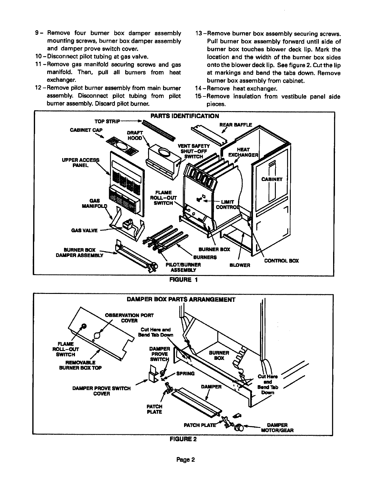
9- Remove four burner box damper assembly
mounting screws, burner box damper assembly
and damper prove switch cover.
10 -Disconnect pilot tubing at gas valve.
11-Remove gas manifold securing screws and gas
manifold. Then, pull all burners from heat
exchanger.
12 -Remove pilot burner assembly from main burner
assembly. Disconnect pilot tubing from pilot
burner assembly. Discard pilot burner.
13-Remove burner box assembly securing screws.
Pull burner box assembly forward until side of
burner box touches blower deck lip. Mark the
location and the width of the burner box sides
onto the blower deck lip. See figure 2. Cut the lip
at markings and bend the tabs down. Remove
burner box assembly from cabinet.
14-Remove heat exchanger.
15-Remove insulation from vestibule panel side
pieces.
...... PARTS IDENTIFICATION
TOP STRIP------_ R_R .FFIE
CABINET C/I_ DRAFT "_
PANEL
GAB
GABVALVE
BURNER BOX
DAMPER ASEEMBLY
PILOT/BURNER BLOWER
ASSEMBLY
FIGURE 1
CONTROL BOX
DAMPER BOX PARTS ARRANGEMENT
O_RVA'nON PORT
Cut Here rand
Bend TabDown
FLAME
BOLL-OUT
8WrlCH
REMOVABLE
BURNER BOX TOP
DAMPER PROVE SWITCH
COVER
DAMPER
PROVE BURNER
SWITC7__
FIGURE 2
Page 2
, ,LAcmE ..............................
IAROUNDDRAFTHOOOOPEN- _I"_=
I ING OF REPLACEMENT HEAT_" I
INSULATION 8TRIP8 ON "_
SIDES AND BOTTOM OF
VESllBULE PANEL ON
REPLACEMENT HEAT
EXCHANGER
FIGURE 3
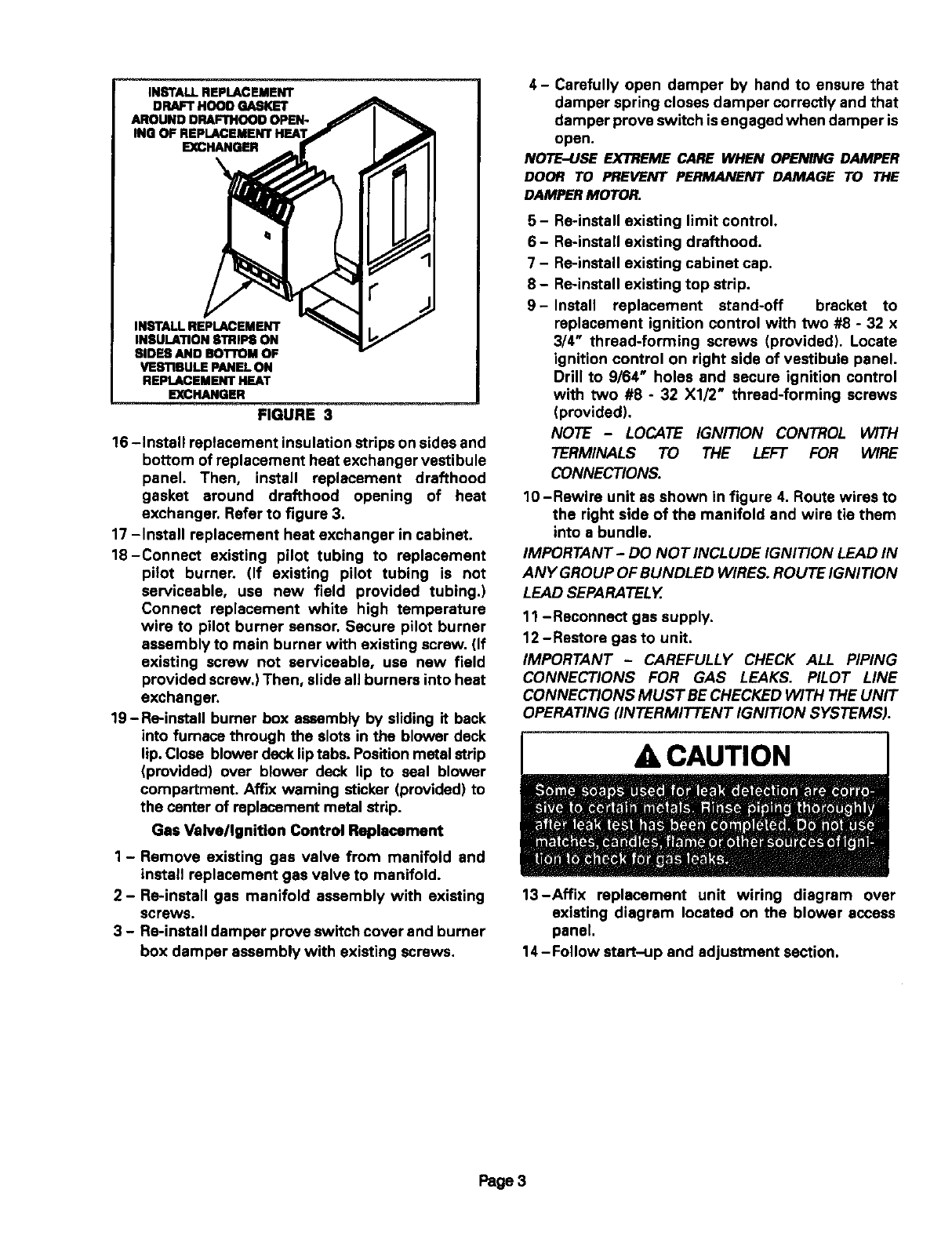
16 -Install replacement insulation strips on sides and
bottom of replacement heat exchanger vestibule
panel. Then, install replacement drafthood
gasket around drafthood opening of heat
exchanger. Refer to figure 3.
17 -Install replacement heat exchanger in cabinet.
18-Connect existing pilot tubing to replacement
pilot burner, (If existing pilot tubing is not
serviceable, use new field provided tubing.)
Connect replacement white high temperature
wire to pilot burner sensor. Secure pilot burner
assembly to main burner with existing screw. (If
existing screw not serviceable, use new field
provided screw.) Then, slide all burners into heat
exchanger.
19-Re-install burner box assembly by sliding it back
into furnace through the slots in the blower deck
lip. Close blower deck lip tabs. Position metal strip
(provided) over blower deck lip to seal blower
compartment. Affix warning sticker (provided) to
the center of replacement metal strip.
Gas Valve/Ignition Control Replacement
1 - Remove existing gas valve from manifold and
install replacement gas valve to manifold.
2- Re-install gas manifold assembly with existing
screws.
3 - Re-install damper prove switch cover and burner
box damper assembly with existing screws.
4- Carefully open damper by hand to ensure that
damper spring closes damper correctly and that
damper prove switch isengaged when damper is
open.
NOTE-USE EXTREME CARE WHEN OPENING DAMPER
DOOR TO PREVENT PERMANENT DAMAGE TO THE
DAMPERMOTOR.
5 - Re-install existing limit control.
6- Re-install existing drafthood.
7 - Re-install existing cabinet cap.
8 - Re-install existing top strip.
9- Install replacement stand-off bracket to
replacement ignition control with two #8 - 32 x
3/4" thread-forming screws (provided). Locate
ignition control on right side of vestibule panel.
Drill to 9/64" holes and secure ignition control
with two #8 - 32 X1/2" thread-forming screws
(provided).
NOTE -LOCATE IGNITION CONTROL WITH
TERMINALS TO THE LEFT FOR WIRE
CONNECTIONS.
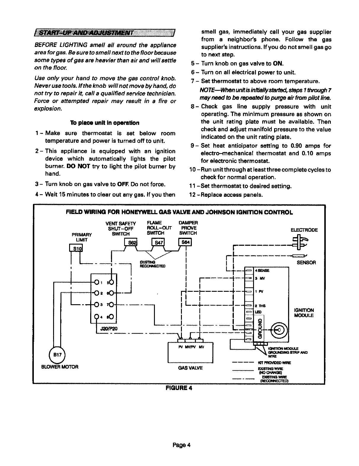
10 -Rewire unit as shown in figure 4, Route wires to
the right side of the manifold and wire tie them
into abundle.
IMPORTANT- DO NOT INCLUDE IGNITION LEAD IN
ANY GROUP OF BUNDLED WIRES. ROUTE IGNITION
LEAD SEPARATELY.
11 -Reconnect gas supply,
12 -Restore gas to unit.
IMPORTANT -CAREFULLY CHECK ALL PIPING
CONNECTIONS FOR GAS LEAKS. PILOT LINE
CONNECTIONS MUST BE CHECKED WITH THE UNIT
OPERATING flNTERMITTENT IGNITION SYSTEMS).
ACAUTION
13-Affix replacement unit wiring diagram over
existing diagram located on the blower access
panel,
14- Follow start-up and adjustment section.
Page 3
BEFORE LIGHTING smell all around the appliance
area for gas. Be sure to smell next to the floor because
some types of gas are heavier than air and will settle
on the floor.
Use only your hand to move the gas control knob.
Never use tools, ff the knob will not move by hand, do
not try to repair it, call a qualified service technician.
Force or attempted repair may result in a fire or
explosion.
To place unit in operation
1-Make sure thermostat is set below room
temperature and power is turned off to unit.
2-This appliance is equipped with an ignition
device which automatically lights the pilot
burner. DO NOT try to light the pilot burner by
hand.
3- Turn knob on gas valve to OFF. Do not force.
4 - Wait 15 minutes to clear out any gas, If you then
smell gas, immediately call your gas supplier
from a neighbor's phone. Follow the gas
supplier's instructions. If you do not smell gas go
to next step.
5-Turn knob on gas valve to ON.
6- Turn on all electrical power to unit.
7 - Set thermostat to above room temperature.
NOTE--When unitisinitiallystarted,steps I through7
may need to be repeated to purge alr from pilot line.
8-Check gas line supply pressure with unit
operating. The minimum pressure as shown on
the unit rating plate must be available. Then
check and adjust manifold pressure to the value
indicated on the unit rating plate.
9- Set heat anticipator setting to 0.90 amps for
electro-mechanical thermostat and 0.10 amps
for electronic thermostat.
10 - Run unit through at least three cornplete cycles to
check for normal operation.
11 -Set thermostat to desired setting.
12 -Replace access panels.
illlllll
FIELD WIRING FOR HONEYWELL GAS VALVE AND JOHNSON IGNmON CONTROL
VENT SAFETY FLAME DAMPER
SHUT-OFF ROLL-OUT PROVE
PRIMARY SWITCH SWITCH SWITCH
UMIT
0,50
"O= 00 --
-Os 70,
04 =0
J_
ELECTRODE
BLOWERMOTOR
Pv MV/PV I/N
GAS VALVE
FIGURE 4
IGNmON MOOULE
GROUNDING81'RIPAND
WIRE
Page 4
