LENNOX Furnace/Heater, Gas Manual L0806909
User Manual: LENNOX LENNOX Furnace/Heater, Gas Manual LENNOX Furnace/Heater, Gas Owner's Manual, LENNOX Furnace/Heater, Gas installation guides
Open the PDF directly: View PDF ![]() .
.
Page Count: 7
®GAS UNITS
KITS AND ACCESSORIES
Technica
_:blications
Litho U.S.A.
©2000 Lennox Industries Inc.
Dallas, Texas, USA 504,122M 90UGF/G26/G32 REPLACEMENT
1/2000
Supersedes 503,908M HEAT EXCHANGER
INSTALLATION INSTRUCTIONS FOR REPLACEMENT HEAT EXCHANGER
(LB-91398A,B,C,D & E) FOR USE WITH 90UGF/G26/G32 SERIES UNITS
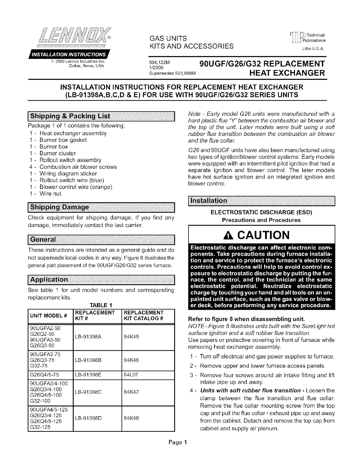
Package 1 of 1 contains the following:
1 - Heat exchanger assembly
1 - Burner box gasket
1 - Burner box
1 - Burner cluster
1 - Rollout switch assembly
4 - Combustion air blower screws
1 - Wiring diagram sticker
1 - Rollout switch wire (blue)
1 - Blower control wire (orange)
1 - Wire nut
Note -Early model G26 units were manufactured with a
hard plastic flue "Y" between the combustion air blower and
the top of the unit. Later models were built using a soft
rubber flue transition between the combustion air blower
and the flue collar.
G26 and 90UGF units have also been manufactured using
two types of ignition/blower control systems, Early models
were equipped with an intermittent pilot ignition that had a
separate ignition and blower control. The later models
have hot surface ignition and an integrated ignition and
blower control.
Check equipment for shipping damage. If you find any
damage, immediately contact the last carrier.
These instructions are intended as a general guide and do
not supersede local codes in any way. Figure 8 illustrates the
general part placement of the 90UGF/G26/G32 series furnace.
See table 1 for unit model numbers and corresponding
replacement kits,
TABLE 1
REPLACEMENT REPLACEMENT
UNIT MODEL #KIT # KIT CATALOG #
90UGFA2-50
G26Q2-50 LB_91398A 84K45
90UGFA3-50
G26Q3*50
90UGFA3-75
G26Q3W5 LB*91398B 84K46
G32W5
G26Q4/5-75 LB*91398E 64L07
90UGFA3/4-100
G26Q3/4-100 LB-91398C 84K47
G26Q4/5-100
G32_100
90UGFA4/5-125
G26Q3/4-125 LB*91398D 84K48
G26Q4/5-125
G32-125
ELECTROSTATIC DISCHARGE (ESD)
Precautions and Procedures
CAUTION
Refer to figure 8 when disassembling unit.
NOTE- Figure 8 illustrates units built with the SureLight hot
surface ignition and a soft rubber flue transition.
Use papers or protective covering in front of furnace while
removing heat exchanger assembly,
1 - Turn off electrical and gas power supplies to furnace.
2 - Remove upper and lower furnace access panels.
3 - Remove four screws around air intake fitting and lift
intake pipe up and away.
4 - Units with soft rubber flue transition - Loosen the
clamp between the flue transition and flue collar,
Remove the flue collar mounting screw from the top
cap and pull the flue collar / exhaust pipe up and away
from the cabinet. Detach and remove the top cap from
cabinet and supply air plenum.
Page 1

Units with hard plastic flue Y - Loosen the lower
clamp of no-hub connector at exhaust line and lift pipe
up and away. Detach unit top cap from cabinet and
supply air plenum and remove the top cap.
5 - If the electrical field make-up box is located inside the
unit, you must remove it.
6 - Mark all gas valve wires and disconnect them from the
valve.
7 - Disconnect gas supply from the gas valve.
8 - Disconnect and remove the condensate line from the
condensate trap (which is on the bottom of the
collector box), Turn the adapter fitting
counterclockwise to remove it from the condensate
trap. The fitting has standard right-hand threads,
9 - Carefully remove the spring clip and boot from the
condensate trap. Drain the condensate trap, and
catch the condensate into a shallow pan. Do not spill
water in the control box.
10 - Remove the drain tube from the cold end collector box
elbow.
11 - Units with hard plastic flue Y- Remove two screws
from the flue Y trap at the cabinet door flange.
12 - Disconnect the 2-pin plug (3-pin plug on G32)from the
combustion air blower. Remove the four screws from
the combustion air blower, then remove the flue Y or
the flue transition and the blower assembly from the
unit. Do not misplace the combustion air blower
orifice.
13 - Units with hard plastic flue Y- Invert the combustion
air blower/flue assembly, and drain the flue Y into the
floor drain.
14-Units with SureLight hot surface ignition -
Disconnect ignitor lead 2-pin plug located just outside
of burner box. Mark and disconnect sensor wire from
ignition control.
Units with intermittent pilot ignition - Mark and
disconnect ignitor lead and sensor wire from ignition
control.
15 - Mark and disconnect pressure switch tubing from both
sides of the pressure switch.
16 - Units with SureLight hot surface ignition - Remove
the limit switch, pressure switch, and the attached
wiring harness from the vestibule panel.
Units with intermittent pilot ignition - Remove the
limit switch, pressure switch, ignition control with its
bracket and the attached wiring harness from the
vestibule panel.
17 - Loosen the two screws that hold the gas manifold
support at the vestibule panel.
18 - Remove the four burner box screws at the vestibule
panel and remove burner box and gas valve/manifold
assembly with bracket.
19- Disconnect the 9-pin plug from the blower
compartment at the blower deck.
20 - Remove the 9-pin plug above the blower deck.
21 - Remove the two screws from the front cabinet flange
at the blower deck, Remove the front screws from the
cabinet at the blower deck on left and right sides.
Cabinet sides must be slightly spread to clear heat
exchanger passage.
22- Remove screws along vestibule sides and bottom
which secure vestibule panel and heat exchanger
assembly to cabinet. Remove heat exchanger.
23 - Remove existing insulation from the mounting angles
located on the cabinet sides.
24-Install the replacement heat exchanger into the
cabinet, and make sure that the clamshells of the heat
exchanger assembly are resting in the notches of the
support which is located at the rear of the cabinet. To
view the clamshell, remove the indoor blower and
examine it through the blower opening.
25-Resecure the heat exchanger supporting screws
along the vestibule sides and bottom.
26 - Resecure cabinet screws on sides and front flange at
blower deck,
27 - Units with SureLight hot surface ignition - Reinstall
limit switch and pressure switch, with attached wiring
harness, on the vestibule panel.
Units with intermittent pilot ignition - Reinstall the
limit switch, pressure switch and ignition control with
its bracket and the attached wiring harness on the
vestibule panel.
28 - Reinstall the 9-pin plug to blower deck and reconnect it
to the the 9-pin plug from below the blower deck.
29 - From the original burner box, unscrew and remove the
burner box cover, and the gas manifold.
30 - Unscrew and remove the fresh air intake fitting from top
of old burner box. Unscrew patch plates from left and
right sides of burner box.
31 - Unscrew and remove the gas manifold and old burner
cluster from the old burner box. On intermittent pilot
G26 units, handle the gas valve and burner cluster
together; this will prevent the pilot tube from being
damaged.
32 - Furnaces with intermittent pilot ignition - Unscrew
and remove original pilot assembly from the old burner
cluster along with "D" wire grommet. Reattach the pilot
assembly to new cluster in the same location. When
you install the burner cluster, the raisedtoggle locks
must be pointing up. Install the pilot assembly on the
underside of the burner cluster, between the two
rightmost burners. See figure 1.
All other units - Remove SureLight ignitor bracket and
sensor bracket from the old burner cluster along with
"D" wire grommet. Reattach ignitor and sensor to the
new burner cluster. The raised toggle locks in the
burner cluster should be pointing up when installed in
the unit. Install the SureLight ignitor on the bottom of the
burner cluster, and install the sensor to the topside of
the bumer cluster. See Figure 2.
Page 2

Burner Assembly with
Pilot Ignition System
(before June 1996)
Burner Box
J
_-_, ]'"
To vestibule panel
Left Patch Plate zj
j
**Toggle Lock__,.j_ X
o_Grommet Right Patch Plate
ij ges
*Burner Cluster
Assembly
** *Burner cluster sits on top of flanges.
Toggle locks on burner assembly must face up.
FIGURE 1
Burner Assembly with
SureLight'M Ignition System
Left Side Patch Plate
X
Sensor
Sensor Brac_
**Toggle Locks I
Burner Box
Flanges
Wire Grommet
To vestibule panel
\
Right Side
Patch Plate
*Burner Cluster
ght Ignitor
Ignitor Bracket *Burner cluster sits on top of flanges.
**Toggle locks on burner assembly must face up.
FIGURE 2
Page 3

Detail View of Burner Cluster Mounting
Burner Box
Raised
To g_e Locks
I
//
Flange _
Screw
Burner Cluster
FIGURE 3
33 - Reattach the new burner cluster into the kit provided
burner box. The burner toggle locks should be facing
up, and the burner should rest on top of the flanges in
the burner box.
34 - Reattach gas manifold and burner box cover onto new
burner box. Make sure that sensor/ignitor wire from the
burner cluster is fed through "D" grommet on the
bottom lip of the bumer box, and that the grommet
makes a good seal with the burner box and cover.
35 - For G26 furnaces built before June 1996 (Serial
Number beginning 5896F or older) - These units
were built without a flame rollout switch installed on the
burner box' right patch plate.
NOTE- Most G26 furnaces will already have been
upgraded with the new rollout switch. Ifyour furnace has
a rollout switch, skip down to the "All Other Units"
paragraph.
A new patch plate assembly is provided with this kit,
complete with rollout switch and pressure barb. Attach
the new right side patch plate into the new burner box,
using the original screws. Locate the plate so that the
rollout switch faces the vest panel (see figure 1). Attach
the left side patch plate into the new burner box using
the original screws.
All other unite - Attach the original left and right patch
plates onto the new burner box. Make sure that the right
side patch plate has the rollout switch oriented towards
the vest panel. See figure 2.
36 - Reattach fresh air intake fitting on top of new burner box
37 - Attach new burner box assembly onto vest panel, using
glass fiber gasket provided. Ensure that the gasket is
visible around all edges of the burner box for a good fit.
NOTE -For the pressure switch to operate properly.
the burner box must be tightly sealed. Verify that the
patch plates, intake air fitting, and burner box cover are
securely fastened and properly located. Ensure that
there is a seal of foam tape around the gas manifold
piping, and that the "D" grommet on the bottom of the
box is flush against the burner box. The burner box
glass fiber gasket must cover all four edges of the box,
and the burner box must be secured tightly to the vest
panel.
CAUTION
38 - Units with soft rubber flue transition - reattach the
flue transition to the combustion air blower outlet.
All units - Use the four long screws (provided) to
attach the combustion air blower to the cold header
box (see figure 8). The plastic orifice must be present
in the blower inlet. See table 2 for the color of the
blower orifice.
TABLE 2
COMBUSTION AIR BLOWER ORIFICE COLORS
Color Model
Grey G26-50, 90UGF-50
Brown. G26-75, 90UGF-75
Blue G26-100, 90UGF-100, G32-100
White G26-125, 90UGF-125 G32-125
Red G32-75
Units with hard plastic flue Y- Slip flue Y onto the
combustion air blower outlet, then use the two original
screws to attach flue Y to the cabinet.
39 - Units with soft rubber flue transition - Resecure top
cap to cabinet; then, reattach and reseal the supply air
plenum to cabinet. Slide flue collar/exhaust pipe
through top cap opening and resecure flue collar
mounting screw. Tighten clamp to secure flue
transition to flue collar.
Units with hard plastic flue Y - Resecure top cap to
cabinet, then reattach and reseal the supply air
plenum to cabinet. Reconnect exhaust pipe to flue Y
with no-hub connector. Tighten no-hub connector
clamp.
40 - Reconnect the combustion air blower 2-pin plug (3-pin
on G32).
41 - Reinstall the condensate line with adapter fitting to
trap on bottom of collector box. Use new Teflon tape to
ensure a leak-flee joint, Reconnect to the condensate
line outside of the unit.
42 - Reconnect the drain line from the flue Y or the flue
transition to the collector box trap elbow.
43 - Reattach the hose tubing to the pressure switch(es).
Refer to figures 4 (single pressure switch) and 5 (dual
pressure switch) for the correct routing of the tubing.
Page 4
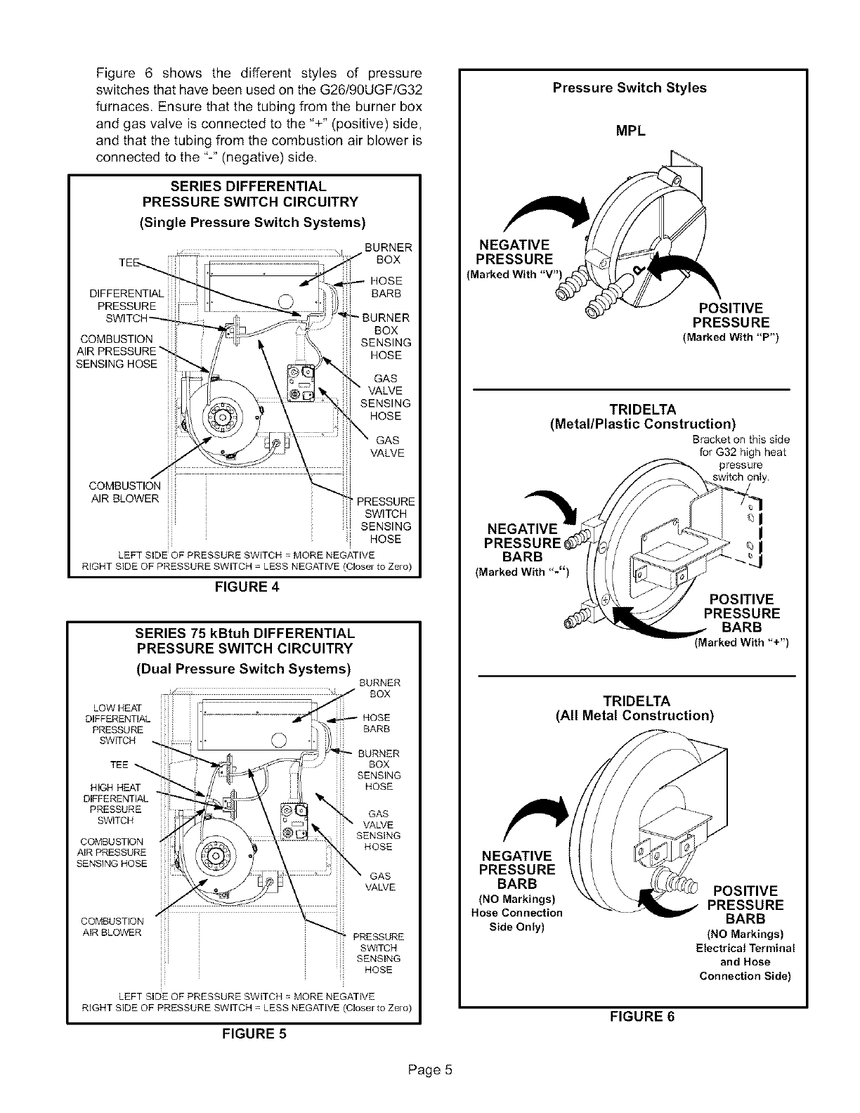
Figure6 showsthe differentstylesof pressure
switchesthathavebeenusedontheG26/90UGF/G32
furnaces.Ensurethatthetubingfromtheburnerbox
andgasvalveisconnectedto the"+"(positive)side,
andthatthetubingfromthecombustionairbloweris
connectedtothe"-"(negative)side.
SERIES DIFFERENTIAL
PRESSURE SWITCH CIRCUITRY
(Single Pressure Switch Systems)
BURNER
BOX
HOSE
BARB
_BURNER
BOX
SENSING
HOSE
GAS
VALVE
SENSING
HOSE
GAS
VALVE
A,RBLOWERiiii PRESSURE
SWITCH
SENSING
ii HOSE
LEFT SIDE OF PRESSURE SWITCH =MORE NEGATIVE
RIGHT SIDE OF PRESSURE SWITCH = LESS NEGATIVE (Closer to Zero)
FIGURE 4
SERIES 75 kBtuh DIFFERENTIAL
PRESSURE SWITCH CIRCUITRY
(Dual Pressure Switch Systems)
LOW HEAT
DIFFERENTIAL
PRESSURE
SW_CH
TEE
HIGH HEAT
DIFFERENTIAL
PRESSURE
SV_TCH
COMBUSTION
AIR PRESSURE
SENSINGHOSE
COMBUSTION
AIRBLOWER
BURNER
BOX
BARB
BURNER
BOX
SENSING
HOSE
GAS
VALVE
SENSING
HOSE
GAS
VALVE
PRESSURE
SWITCH
SENSING
_; HOSE
LEFT SIDE OF PRESSURE SWITCH = MORE NEGATIVE
RIGHT SIDE OF PRESSURE SWITCH = LESS NEGATIVE (Closer to Zero)
FIGURE 5
NEGATIVE
PRESSURE
Marked With "V"
NEGATIVE
PRESSURE
BARB
(Marked With "-")
NEGATIVE
PRESSURE
BARB
(NO Markings)
Hose ConneXion
Side Only)
Pressure Switch Styles
MPL
POSITIVE
PRESSURE
(Marked With "P')
TRIDELTA
(Metal/Plastic Construction)
Bracket on this side
for G32 high heat
pressure
I
POSITIVE
PRESSURE
BARB
(MarkedWith"+')
TRIDELTA
(All Metal Construction)
POSITIVE
PRESSURE
BARB
(NO Markings)
Electrical Terminal
and Hose
Connection Side)
FIGURE 6
Page 5
44- Units with SureLight hot surface ignition -
Reconnect ignitor lead 2-pin plug located just outside
of burner box. Reconnect sensor wire to ignition
control.
Units with intermittent pilot ignition -
Reconnect ignitor lead and sensor wire to ignition
control.
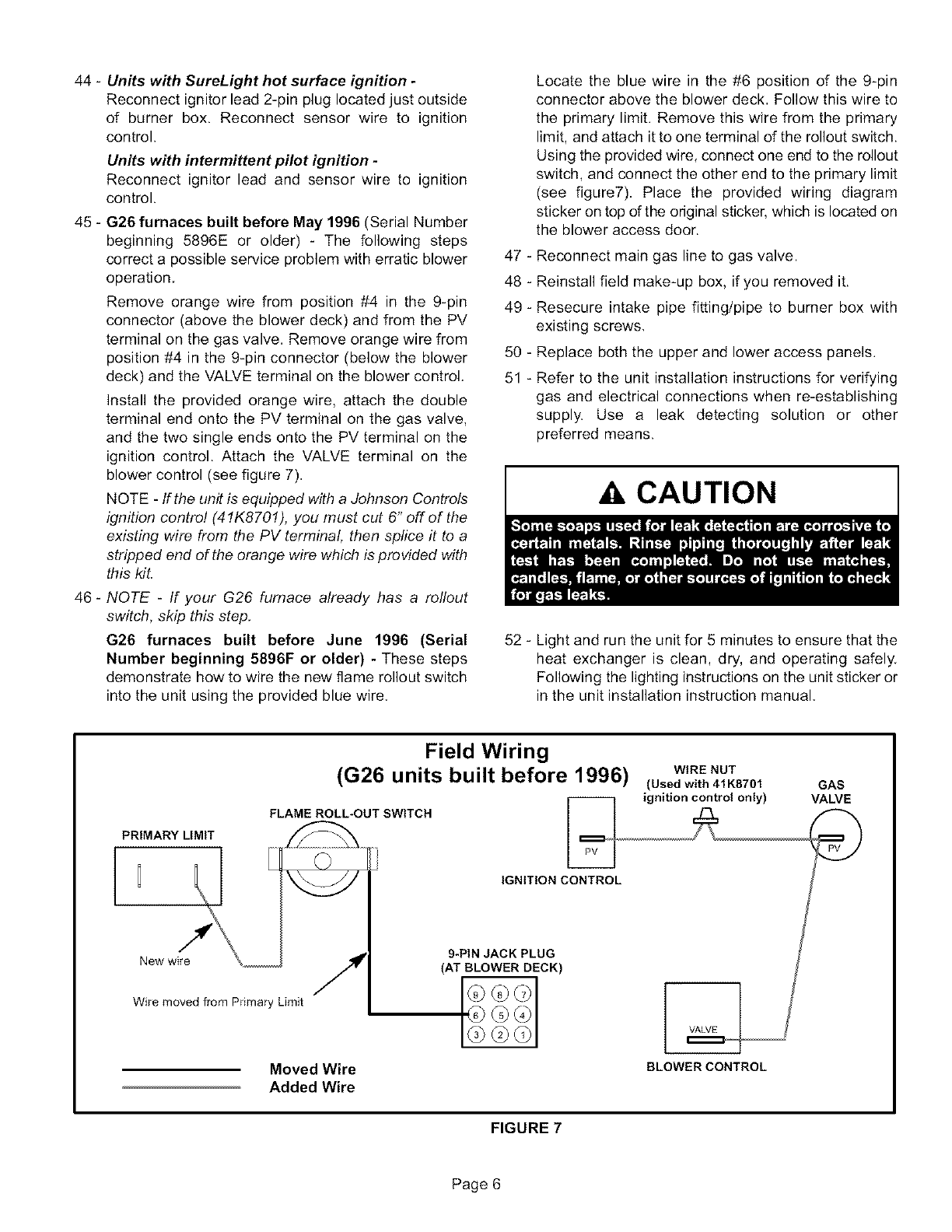
45 - G26 furnaces built before May 1996 (Serial Number
beginning 5896E or older) - The following steps
correct a possible service problem with erratic blower
operation.
Remove orange wire from position #4 in the 9-pin
connector (above the blower deck) and from the PV
terminal on the gas valve. Remove orange wire from
position #4 in the 9-pin connector (below the blower
deck) and the VALVE terminal on the blower control.
Install the provided orange wire, attach the double
terminal end onto the PV terminal on the gas valve,
and the two single ends onto the PV terminal on the
ignition control. Attach the VALVE terminal on the
blower control (see figure 7).
NOTE - If the unit is equipped with a Johnson Controls
ignition contro! (41K8701), you must cut 6" off of the
existing wire from the PV terminal, then splice it to a
stripped end of the orange wire which is provided with
this kit.
46 - NOTE -If your G26 furnace already has a rollout
switch, skip this step.
G26 furnaces built before June 1996 (Serial
Number beginning 5896F or older) - These steps
demonstrate how to wire the new flame rollout switch
into the unit using the provided blue wire.
Locate the blue wire in the #6 position of the 9-pin
connector above the blower deck, Follow this wire to
the primary limit. Remove this wire from the primary
limit, and attach it to one terminal of the rollout switch.
Using the provided wire, connect one end to the rollout
switch, and connect the other end to the primary limit
(see figure7). Place the provided wiring diagram
sticker on top of the original sticker, which is located on
the blower access door.
47 - Reconnect main gas line to gas valve.
48 - Reinstall field make-up box, if you removed it.
49 - Resecure intake pipe fitting/pipe to burner box with
existing screws,
50 - Replace both the upper and lower access panels.
51 - Refer to the unit installation instructions for verifying
gas and electrical connections when re-establishing
supply. Use a leak detecting solution or other
preferred means.
CAUTION
52 - Light and run the unit for 5 minutes to ensure that the
heat exchanger is clean, dry, and operating safely.
Following the lighting instructions on the unit sticker or
in the unit installation instruction manual,
PRIMARY LIMIT
Field Wiring
(G26 units built before 1996)
FLAME ROLL-OUT SWITCH
IGNITION CONTROL
WIRE NUT
(Used with 41K8701 GAS
ignition control only) VALVE
Wire moved from Primary Limit
Moved Wire
Added Wire
9-PIN JACK PLUG
(AT BLOWER DECK)
BLOWER CONTROL
FIGURE 7
Page 6
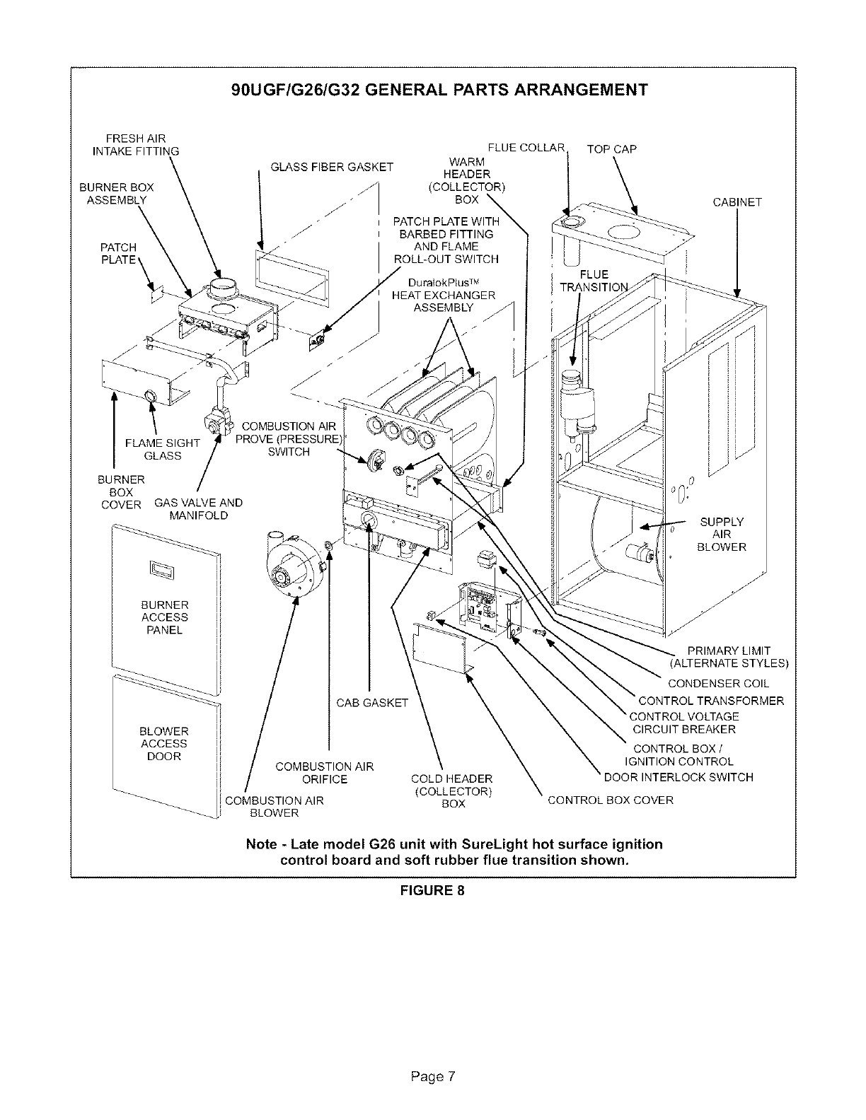
90UGF/G26/G32 GENERAL PARTS ARRANGEMENT
FRESH AIR
INTAKE FITTING
BURNER BOX
ASSEMBLY
PATCH
PLATE'
GLASS FIBER GASKET
FLUE COLLAR
WARM
HEADER
(COLLECTOR)
BOX
PATCH PLATE WITH
BARBED FITTING
AND FLAME
ROLL-OUT SWITCH
DuralokP_us TM
HEAT EXCHANGER
ASSEMBLY
COMBUSTION AIR
FLAME SIGHT
GLASS SWITCH
BURNER
BOX
COVER GAS VALVE AND
MANIFOLD
u
u
BURNER lli
ACCESS I
PANEL Iii
U
U
I
u
BLOWER lli
ACCESS I
DOOR lli
U
U
U
--_ i COMBUSTION AIR
-_-_ I BLOWER
CAB GASKET
COMBUSTION AIR
ORIFICE COLD HEADER
(COLLECTOR)
BOX
TOP CAP
CABINET
FLUE
SUPPLY
AIR
BLOWER
PRIMARY LIMIT
CONDENSER COIL
CIRCUIT BREAKER
CONTROL BOX /
IGNITION CONTROL
CONTROL BOX COVER
Note - Late model G26 unit with SureLight hot surface ignition
control board and soft rubber flue transition shown.
FIGURE 8
Page 7
