LENNOX Furnace/Heater, Gas Manual L08A6037
User Manual: LENNOX LENNOX Furnace/Heater, Gas Manual LENNOX Furnace/Heater, Gas Owner's Manual, LENNOX Furnace/Heater, Gas installation guides
Open the PDF directly: View PDF ![]() .
.
Page Count: 5
LENND
2004 Lennox Industries Inc.
DaItas, Texas, USA
GAS KITS & ACCESSORIES
Litho U.S.A.
504,986M
11/2004 HIGH ALTITUDE KIT
INSTALLATION INSTRUCTIONS FOR HIGH ALTITUDE KIT (83M75) USED WITH
G43UF & G51MP UNITS FUELED BY LP/PROPANE GAS
IWARNING IACAUTION
1 -
2 -
Package 1 of I contains the following: 3 -
7 - Main burner orifices (0.086)
1 - White-Rodgers 36G gas valve conversion kit 4-
1 - Bag assembly containing:
1 - Honeywell VR8205 gas valve conversion kit
1 - Supply pressure switch (used with Honeywell
valve only)
1 - Gas valve inlet tap fitting (used with Honeywell
valve only) 5 -
1- Wiring harness (used with Honeywell valve
only)
1 - Gas converter sticker
1 - Nameplate conversion sticker
High altitude kit (83M75) is used to convert G43UF and
G51MP units which are fueled by LP/propane gas for
operation at altitudes from 7501 to 10,000 ft. (2287m to
3048 m). Units installed in these high altitude
applications also require installation of a replacement
pressure switch, which is ordered separately,
,&,CAUTION
Set the thermostat to the lowest setting. If the gas
supply line has been connected, shut off the gas
supply to the furnace, then disconnect the electrical
power.
Remove the heating compartment access panel.
Remove burner box cover, if necessary. Turn the
automatic gas valve knob, or switch the gas valve
lever, to the OFF position (figures 8 and 9).
Disconnect the gas supply (if installed) from the gas
valve. Mark the wires for identification and
disconnect the wiring at the gas valve
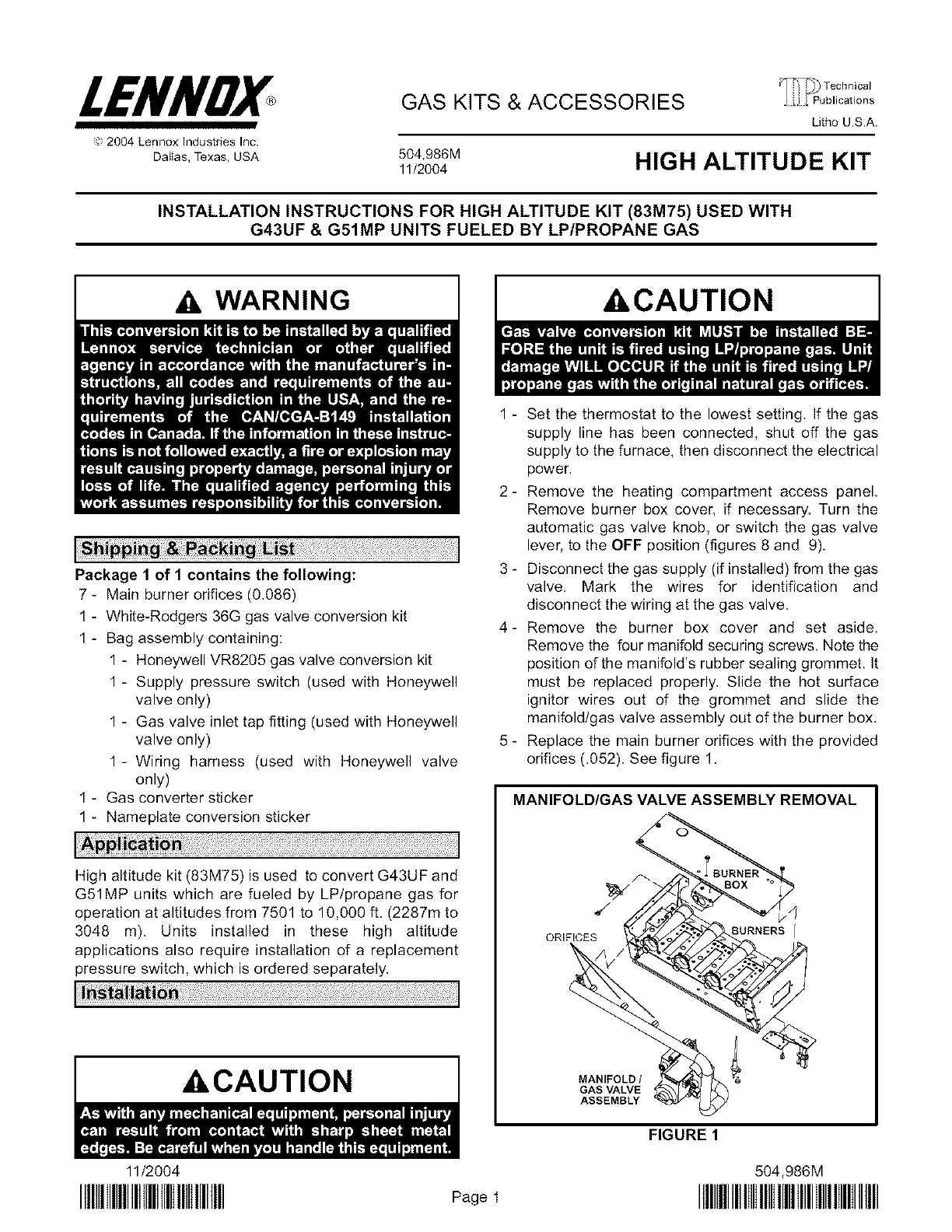
Remove the burner box cover and set aside.
Remove the four manifold securing screws. Note the
position of the manifold's rubber sealing grommet. It
must be replaced properly. Slide the hot surface
ignitor wires out of the grommet and slide the
manifold/gas valve assembly out of the burner box.
Replace the main burner orifices with the provided
orifices (.052). See figure 1.
MANIFOLD/GAS VALVE ASSEMBLY REMOVAL
ORIFICES
,4
BURNERS /
MANIFOLD /
GAS VALVE
ASSEMBLY
FIGURE 1
11/2004 504,986M
IIIIIIlIIIIIIIIIlIIIHIIIIIIIIIIIIIIII Page1 IIIIIIIIIIIIIIIIIIIIIIIIIIlIIIIIIIIIIlIIIIIIIIIIII
IMPORTANT AIMPORTANT
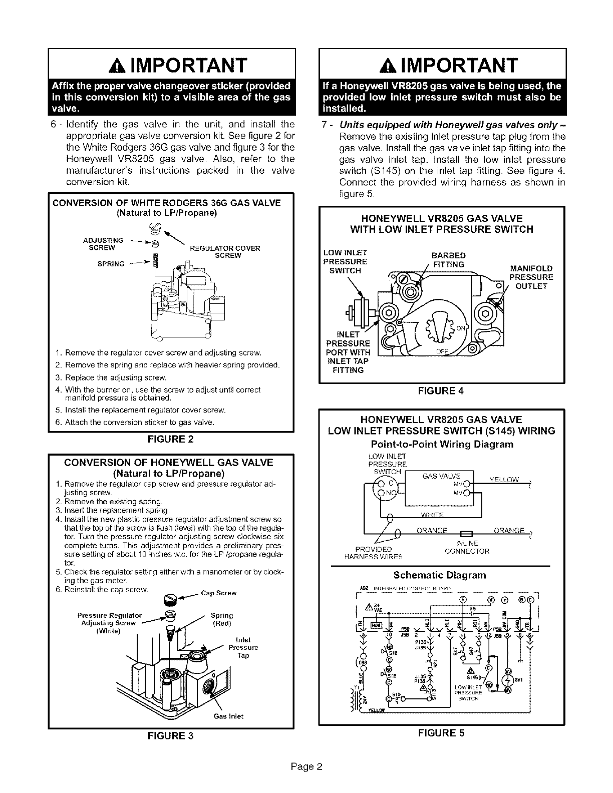
6 - Identify the gas valve in the unit, and install the
appropriate gas valve conversion kit. See figure 2 for
the White Rodgers 36G gas valve and figure 3 for the
Honeywell VR8205 gas valve. Also, refer to the
manufacturer's instructions packed in the valve
conversion kit.
CONVERSION OF WHITE RODGERS 36G GAS VALVE
(Natural to LP/Propane)
ADJUSTING
SCREW REGULATOR COVER
SPRING -- --'_" S_REW
1. Remove the regulator cover screw and adjusting screw.
2. Remove the spring and replace with heavier spring provided.
3. Replace the adjusting screw.
4. With the burner on, use the screw to adjust untiI correct
manifold pressure is obtained.
5. InstatI the replacement regulator cover screw.
6. Attach the conversion sticker to gas vatve.
FIGURE 2
CONVERSION OF HONEYWELL GAS VALVE
(Natural to LP/Propane)
1. Remove the regulator cap screw and pressure regulator ad=
justing screw.
2. Remove the existing spring.
3. Insert the replacement spring.
4. Install the new plastic pressure regulator adjustment screw so
that the top of the screw is flush (level) with the top of the regula-
tor. Turn the pressure regulator adjusting screw clockwise six
complete turns. This adjustment provides a preliminary pres-
sure setting of about 10 inches w.c. for the LP/propane regula-
tor.
5. Check the regulator setting either with a manometer or by clock-
ing the gas meter.
6. Reinstall the cap screw. _=.,..,.. Cap Screw
Pressure Regulator Spring
Adjusting Screw -""_" "_" (Red)
(White) Inlet
Pressure
Tap
Gas Inlet
FIGURE 3
7 - Units equipped with Honeywell gas valves only -
Remove the existing inlet pressure tap plug from the
gas valve. Install the gas valve inlet tap fitting into the
gas valve inlet tap. Install the low inlet pressure
switch ($145) on the inlet tap fitting. See figure 4.
Connect the provided wiring harness as shown in
figure 5.
HONEYWELL VR8205 GAS VALVE
WITH LOW INLET PRESSURE SWITCH
LOW INLET BARBED
PRESSURE FITTING
SWITCH MANIFOLD
PRESSURE
/OUTLET
INLET
PRESSURE
PORT WITH
INLET TAP
FITTING
FIGURE 4
HONEYWELL VR8205 GAS VALVE
LOW INLET PRESSURE SWITCH ($145) WIRING
Point-to-Point Wiring Diagram
LOW INLET
PRESSURE
SWITCH GAS VALV_EvoI YELLOW (_
ORANGE _ ORANGE
_ INLINE <
PROVIDED CONNECTOR
HARNESS WIRES
Schematic Diagram
Ag2 _NTEGRATED CONTROL BOARD
[
,-",- oi °'
$_/ J58 2 I 4_S J58 9 8
!:o ?dlt
Si45 _l
LOW _NLET
FIGURE 5
Page 2
(pressure switch rear barb to
collector box negative tap)
Pressure Switch Replacement
(G51MP Shown)
COLLECTOR BOX NEGATIVE
PRESSURE TAP _.
COLLECTOR BOX POSITIVE
PRESSURE TAPS
FLUE COLLECTOR BOX
/
BLACK TUBING /
(pressure switch front barb to
collector box positive tap)
COLLECTOR BOX NEGATIVE
PRESSURE TAP
RED TUBING
(pressure switch rear barb to
collector box negative tap)
FIGURE 6
8 - Re-install the manifold/valve assembly. Ensure that
the manifold grommet is properly positioned in the
bumer box. Re-insert the igniter wire into the
grommet slot, Replace the burner box cover and
re-connect wiring to the gas valve.
9 - G43UF and G51MP units installed at altitudes of
7501 to 10000 feet above sea level require a
replacement pressure switch assembly(ies) as listed
in table 1,
a - Make note of the routing of the pressure switch
tubing, Tubing must be replaced correctly,
Remove the tubing from the barbed fitting on the
pressure switch(es).
b - Remove screw(s) which secure pressure switch
assembly(ies). Install replacement pressure
switch(es) using existing screw(s),
c-Securely attach flexible tubing to fitting on
replacement pressure switch assembly(ies).
See figure 6. Ensure that tubing is routed
correctly,
AWARNING
TABLE 1
Pressure Switch Requirements at Altitudes
of 7501 to 10000 Feet above Sea Level
Model Input
Size Pressure Switch Quantity Required
G43UF-045
G43UF=070 56M06 1
G43UF*090(H) 56M07 1
G43UFq 10(H)
G43UF-135 60M35 1
G51MP-045
G51MP-070 56M06 2
G51MP-090
G51MP=110 56M07 2
G51MP=135 60M35 2
Pressure switch is factory set. No adjustment necessary.
10 - Reconnect the gas supply to the manifold and turn on
gas supply to unit,
NOTE -ff the unit is equipped with the Honeywell
VR8205 gas valve and the gas piping is entering the
cabinet from the right-hand side, a 4" nipple must be
used at the inlet to provide clearance for the low inlet
pressure switch. See figure 7.
Page 3
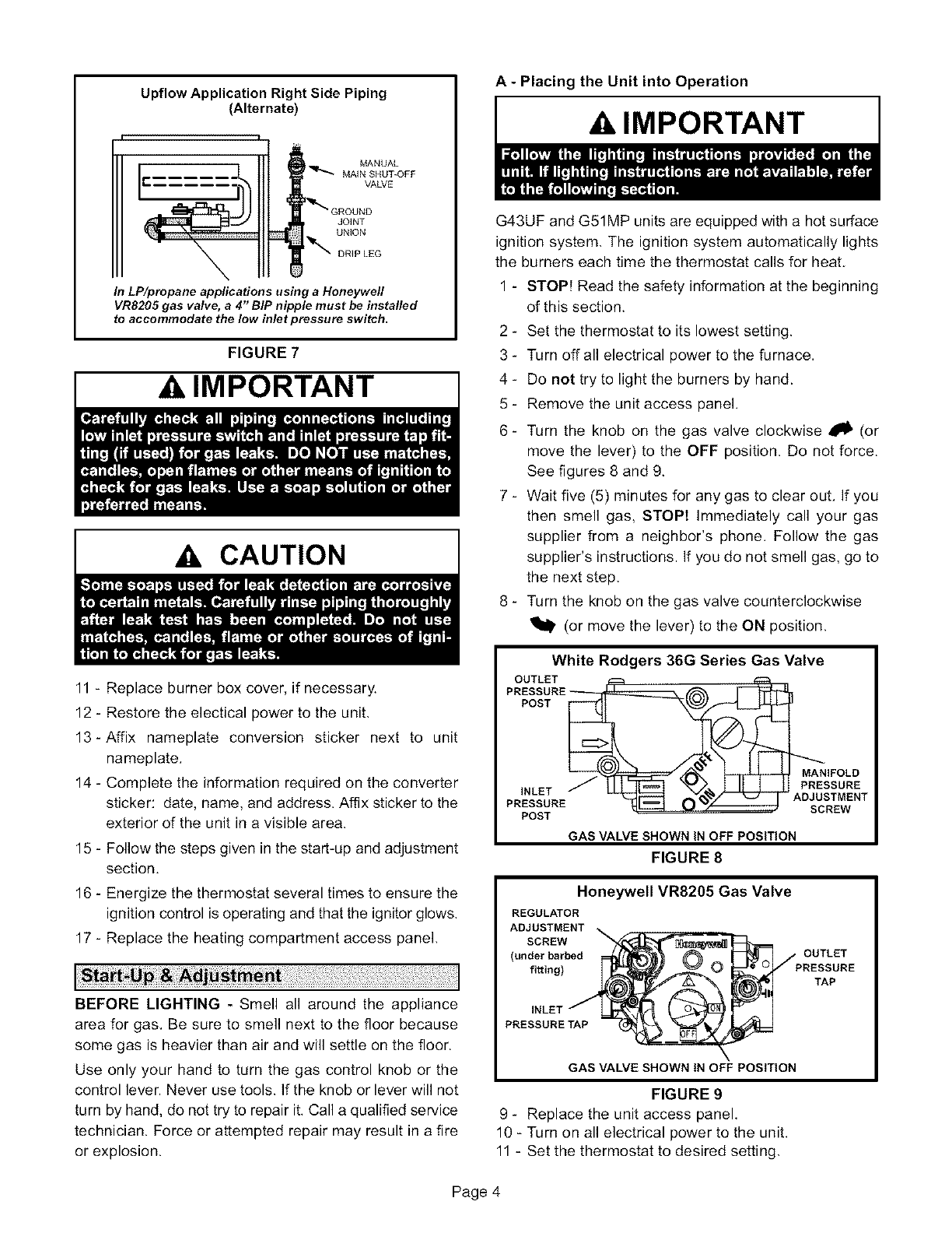
Upflow Application Right Side Piping
(Alternate)
MANUAL
MAIN SHUT-OFF
VALVE
I
In LP/propane applications using aHoneywell
VR8205 gas valve, a4" BIP nipple must be installed
to accommodate the low inlet pressure switch.
FIGURE 7
IMPORTANT I
A CAUTION
11 - Replace burner box cover, if necessary.
12 - Restore the electical power to the unit.
13-Affix nameplate conversion sticker next to unit
nameplate.
14 - Complete the information required on the converter
sticker: date, name, and address. Affix sticker to the
exterior of the unit in a visible area.
15 - Follow the steps given in the start-up and adjustment
section.
16 - Energize the thermostat several times to ensure the
ignition control is operating and that the ignitor glows.
17 - Replace the heating compartment access panel.
BEFORE LIGHTING - Smell all around the appliance
area for gas. Be sure to smell next to the floor because
some gas is heavier than air and will settle on the floor,
Use only your hand to turn the gas control knob or the
control lever, Never use tools. If the knob or lever will not
turn by hand, do not try to repair it. Call a qualified service
technician. Force or attempted repair may result in a fire
or explosion.
A - Placing the Unit into Operation
AIMPORTANT
G43UF and G51MP units are equipped with a hot surface
ignition system. The ignition system automatically lights
the burners each time the thermostat calls for heat
1 - STOP! Read the safety information at the beginning
of this section.
2 - Set the thermostat to its lowest setting.
3 - Turn offall electrical power to the furnace.
4- Do not try to light the burners by hand.
5 - Remove the unit access panel.
6- Turn the knob on the gas valve clockwise _ (or
move the lever) to the OFF position. Do not force.
See figures 8 and 9.
7 - Wait five (5) minutes for any gas to clear out. If you
then smell gas, STOP! Immediately call your gas
supplier from a neighbor's phone. Follow the gas
supplier's instructions. If you do not smell gas, go to
the next step.
8 - Turn the knob on the gas valve counterclockwise
(or move the lever) to the ON position.
White Rodgers 36G Series Gas Valve
OUTLET
PRESSURE_
POST
INLET /
PRESSURE
POST
GAS VALVE SHOWN IN OFF POSITION
FIGURE 8
MANIFOLD
PRESSURE
ADJUSTMENT
SCREW
Honeywell VR8205GasValve
REGULATOR
AD_t_NT _ _ OUTLET
(underbarbedfi_ing)__/_ (/_ PRE_URE
INLET_
PRESSURE
GAS VALVE SHOWN tN OFF POSITION
FIGURE 9
9 - Replace the unit access panel
10 - Turn on all electrical power to the unit.
11 - Set the thermostat to desired setting.
Page 4
12-If the furnacewill not operate,see the section
"TurningOffGastotheUnit"andcallyourservice
technicianorgassupplier.
B - Turning Off Gas To the Unit
1-Set the thermostat to its lowest setting.
2 - Turn off all the electrical power to the unit.
3 - Remove the heat section access panel.
4 - Turn the knob on the gas valve clockwise111P (or
move the lever) to the OFF position. Do not force.
C - Verifying the Gas Line Pressure
Check the gas line pressure while the unit is operating.
Maintain a minimum of 11.0" w.c. (2.74kPa) and a
maximum of 13.0" w.c. (3.23kPa). See figures 8 and 9 for
the location of the inlet pressure tap on the gas valve.
D - Measuring & Adjusting the Manifold Pressure
1 - Connect a manometer to outlet tap on gas valve.
2 - Start unit and allow 5 minutes for the unit to stabilize.
3 - Check the burner flame. The flame should be stable
and should not lift from the burners. The flame should
be predominantly blue with orange bursts when the
gas enters the heat exchanger. The flame should
burn continuously from all burners.
4 - After allowing the unit to stabilize for 5 minutes,
check the manifold pressure. Manifold pressure for
all units using LP/propane gas should be 10.0" w.c.
(2.5kPa). See figures 8 and 9 for the location of the
pressure adjustment screws.
NOTE -Turn off the unit and remove the manometer as
soon as you have obtained an accurate reading. Replace
the pressure tap plug.
During this test procedure, the unit will be oveffiring:
• Operate unit only long enough to obtain accurate
reading to prevent overheating heat exchanger.
• Attempts to clock gas meter during this procedure will
be inaccurate. Measure gas flow rate only during
normal unit operation.
5- When test is complete, return hose to gas valve
barbed fitting.
AIMPORTANT
E-Verifying the Gas Rate
The gas input must not exceed the amount shown on the
unit's rating plate. In cases where gas is not metered, the
service technician who is performing the conversion will
need to install a temporary meter to perform this
procedure. Check the input by the following method:
Contact the utility company or the LP/propane gas
distributor for the heating value of the gas. Shut off all
other appliances during the input check.
Locate the meter just upstream in regulated pressure
[11.0" w.c. to 13.0" w.c. (2.74kPa to 3.23kPa)]. To check
the Btu input rate. time the dial hand on the gas meter for
at least one revolution, using the one cubic foot dial.
To assure accurate measurements, use temperature and
pressure correction factors for the meter.
To determine the number of seconds required for the flow
of one cubic foot of gas, use the following formula:
(BTU Content)
Heating Value Of Gas X 3600
Furnace Btuh Input
Example: 2500 BTU gas
Furnace input 100,000 BTUH
Seconds for one cubic foot =
2500 X 3600 = 90 seconds
100,000
Page 5
