LG ELECTRONICS LGC500W Dual Mode Cellular Phone (AMPS/CDMA) User Manual service manual
LG Electronics, Inc. Dual Mode Cellular Phone (AMPS/CDMA) service manual
UserManual.wiki
>
LG ELECTRONICS
>
LGC500W User Manual
>
Service Manual
Contents
1.
Users Manual
2.
Service Manual
Service Manual
Navigation menu
Upload a User Manual
Namespaces
Wiki Guide
HTML
PDF
Info
Views
User Manual
Discussion / Help
Navigation
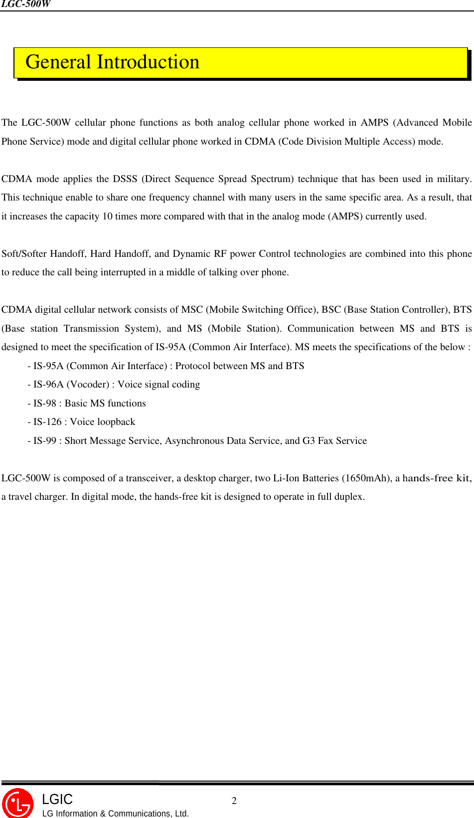
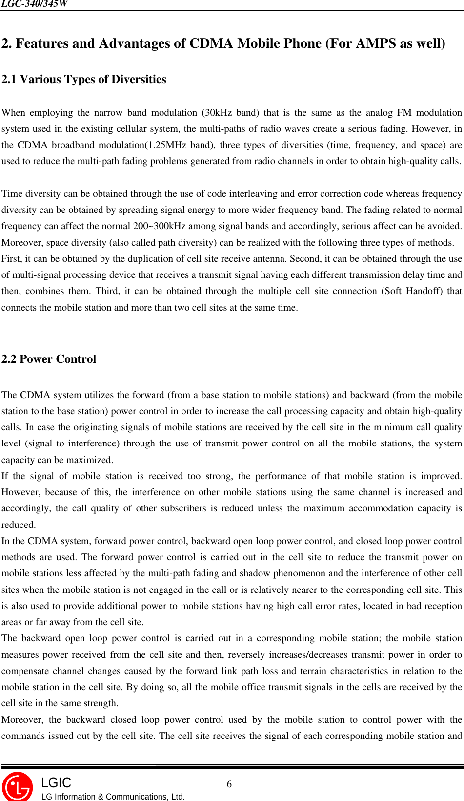
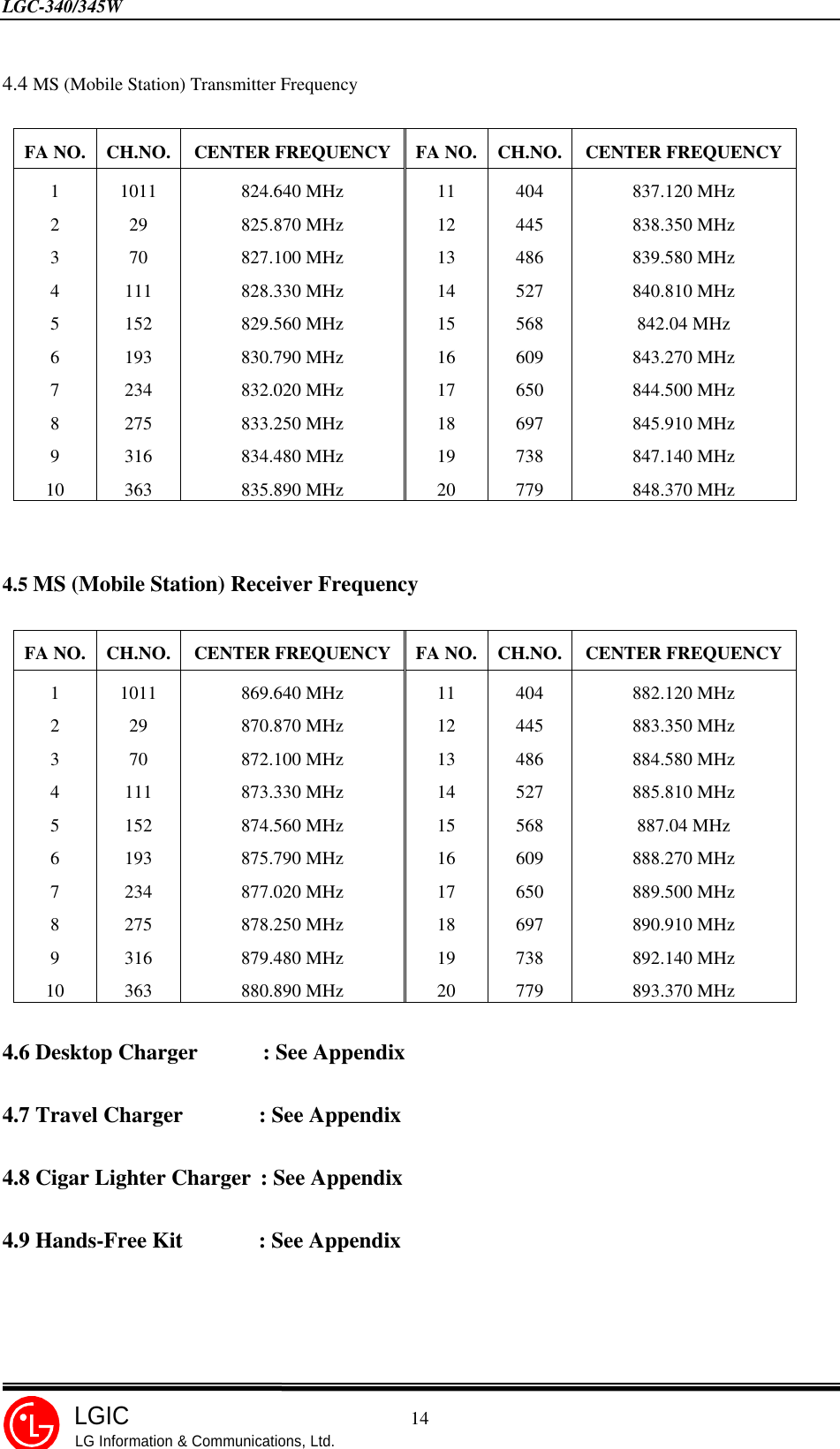
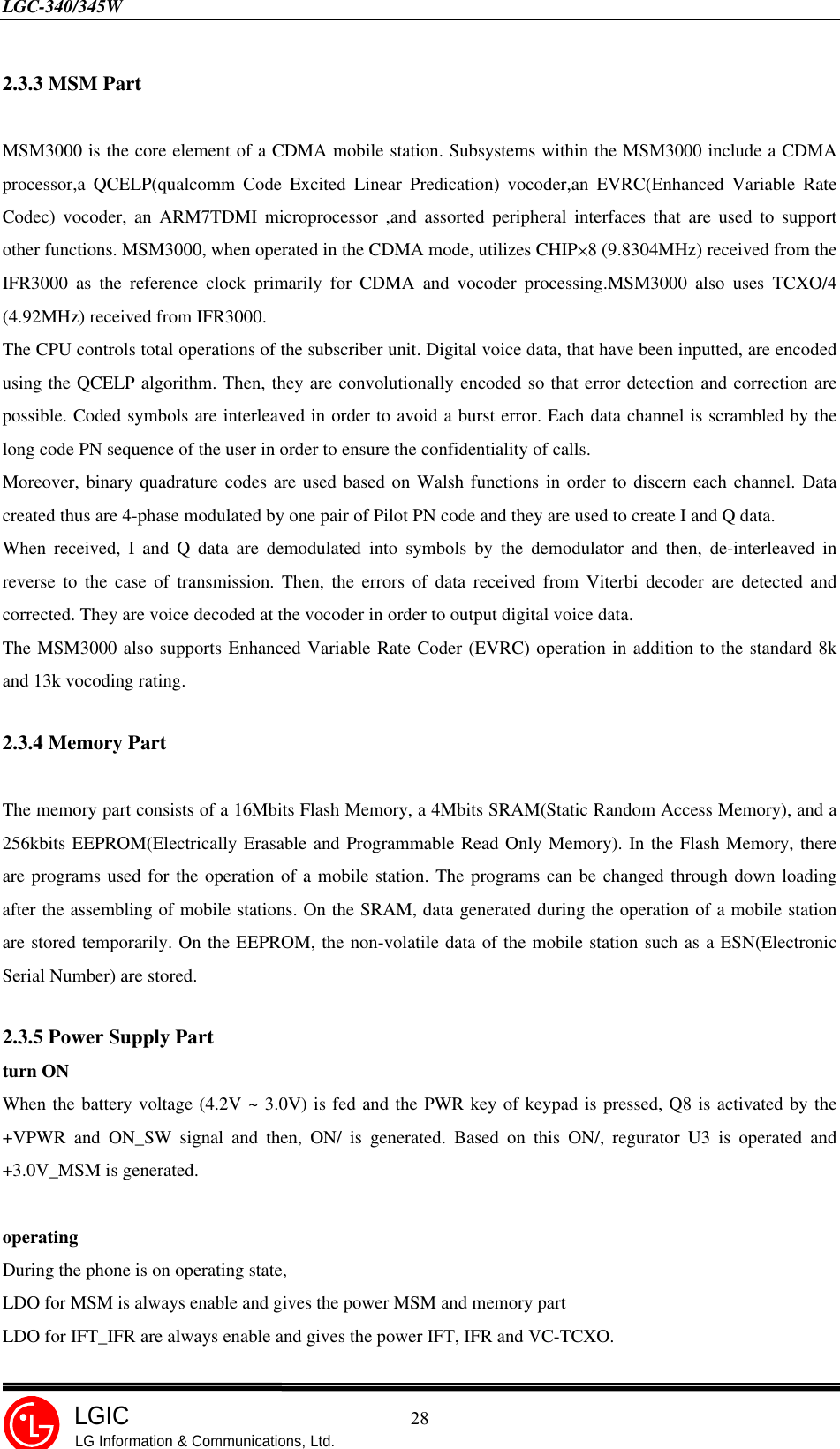
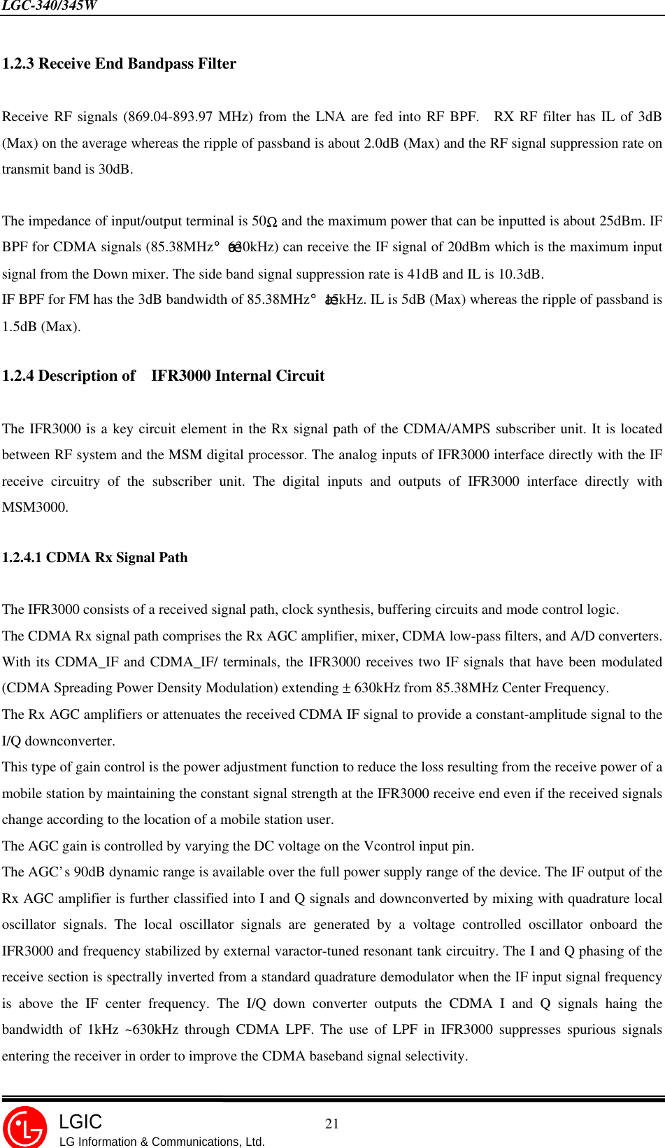
![LGC-340/345W 17LGICLG Information & Communications, Ltd.1. Telephone Number and NAM Programming Method • Press MENU+4+0 and then, press the password made up of six digits(Default:000000). Then, the following Menu is appeared. • Press 1 to program the telephone number and NAM. • Select one NAM (the registration requires NAM1 as default). • Edit ESN(if you want, but not recommended) , then press [OK]. • Enter the phone number, then press [OK]. • Edit NAM 1 HOME SID, then press [OK]. CHAPTER 2. NAM Input Method (Inputting of telephone numbers included)1 : NAM 12 : NAM 23 : NAM 34 : NAM 41 : Prog Mode2 : Pref. Mode3 : ER Mode4 : PRLESNNAM 1 PHONENUMBERNAM 1 HOME SID](https://usermanual.wiki/LG-ELECTRONICS/LGC500W.Service-Manual/User-Guide-58543-Page-18.png)
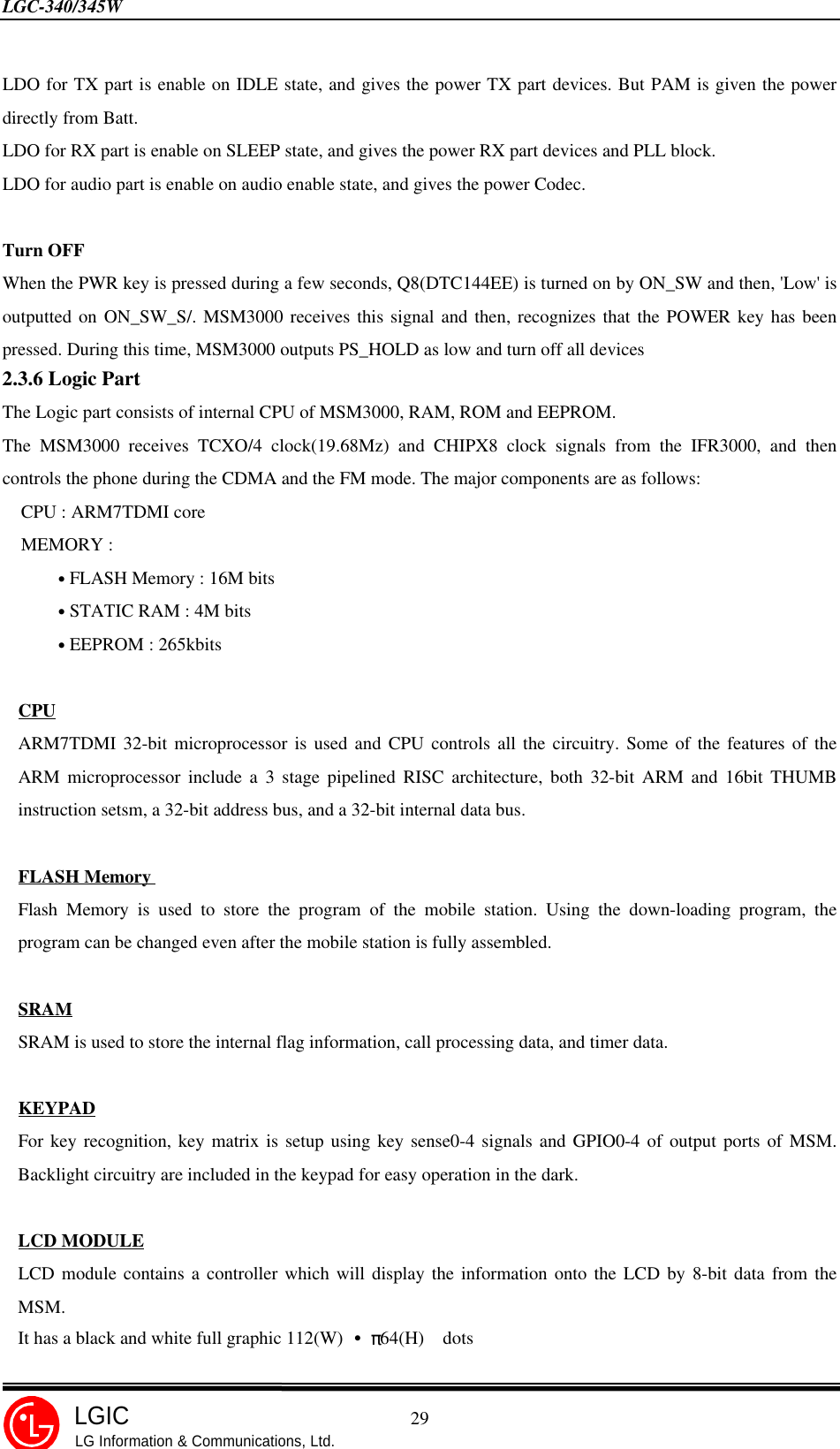
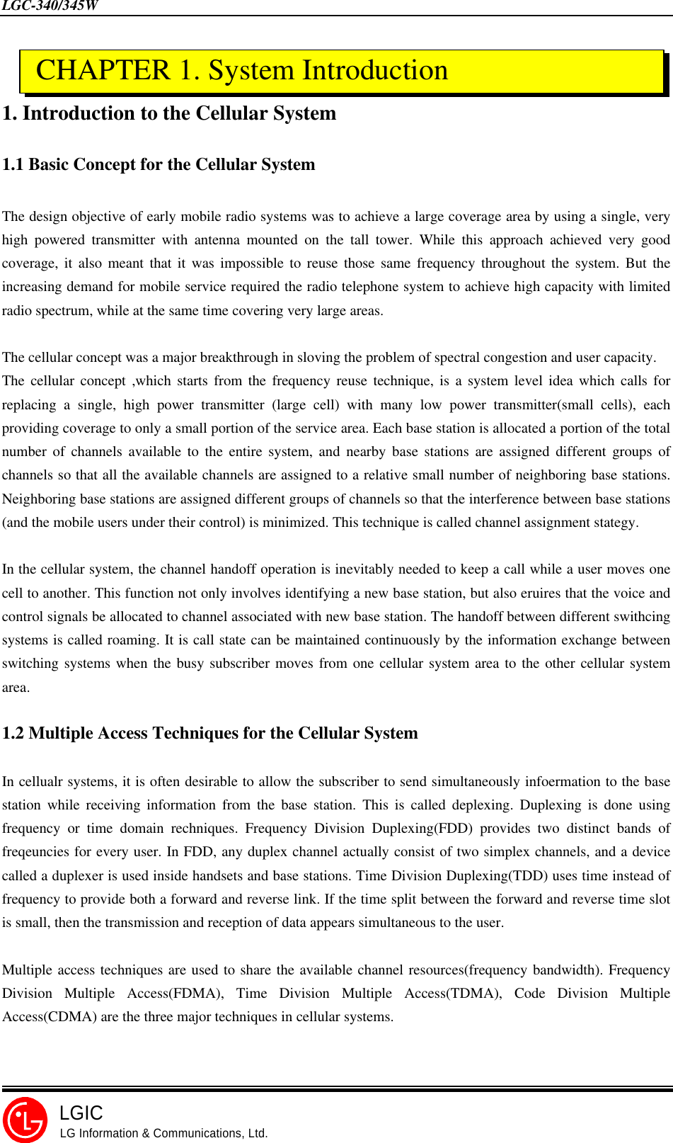
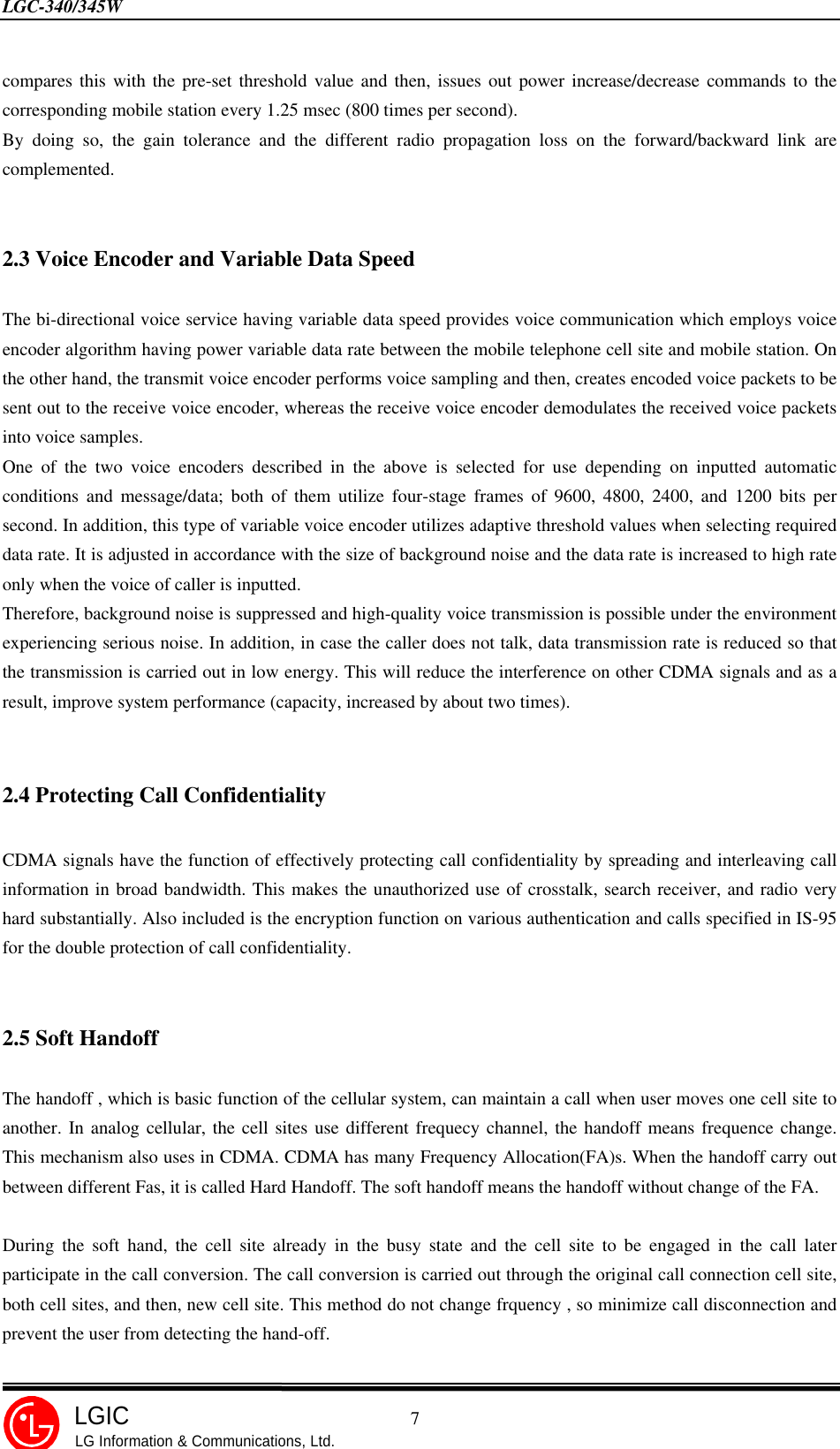
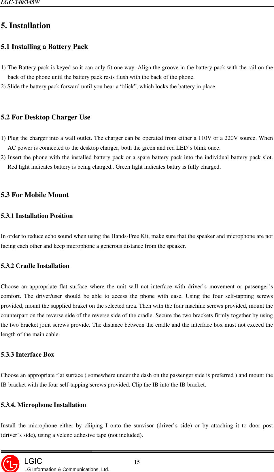
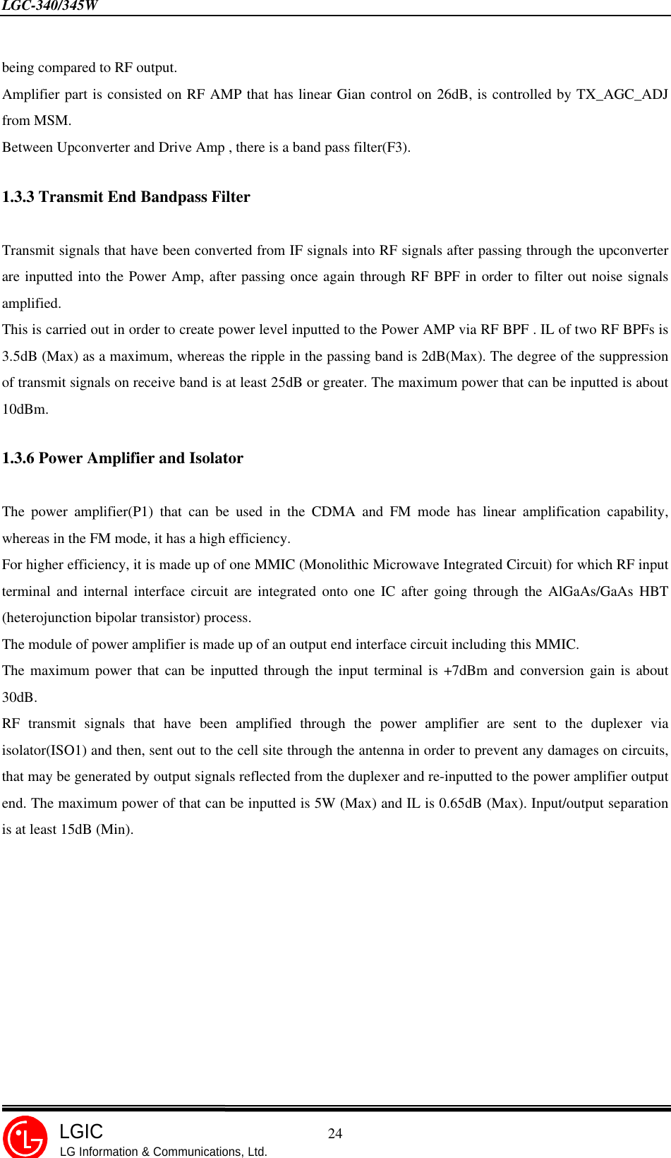
![LGC-340/345W 18LGICLG Information & Communications, Ltd. • Edit the name of NAM1, the press [OK]. ‘NAM 1 NAME’ may display the name of the service provider. • Now, the basic programming is completed. To reset the handset, press [EXIT]. If you want to program detail informtions for NAM 1, press [MORE].The detail programming method is same as basic programming. Set up required values and then, press the [OK]soft key in an effort to move to the next screen. To return to the last item, press the left arrow (3*). The editableNAM items are followed:SERVICE SEC. CODENAM 1 LOCK_OUT SYSTEM 1NAM 1 CDMA PHONE MUNBERNAM 1 MOBILE COUNTRY CODENAM 1 MOBILE NETWORK CODENAM 1 MOBILE STATION ID #NAM 1 CDMA HOME SID 1NAM 1 CDMA HOME NID 1NAM 1 CDMA HOME SID 2NAM 1 CDMA HOME NID 2NAM 1 CDMA HOME SID 3NAM 1 CDMA HOME NID 3NAM 1 CDMA HOME SID 4NAM 1 CDMA HOME NID 4NAM 1 AMPS PHONE NUMBERNAM 1 AMPS HOME SIDPHONE MODELSLOT CYCLE INDEX¡Ø Editing this items is not recommended.NAM 1 NAMEBASIC NAM 1PROGRAMMINGIS COMPLETED](https://usermanual.wiki/LG-ELECTRONICS/LGC500W.Service-Manual/User-Guide-58543-Page-19.png)
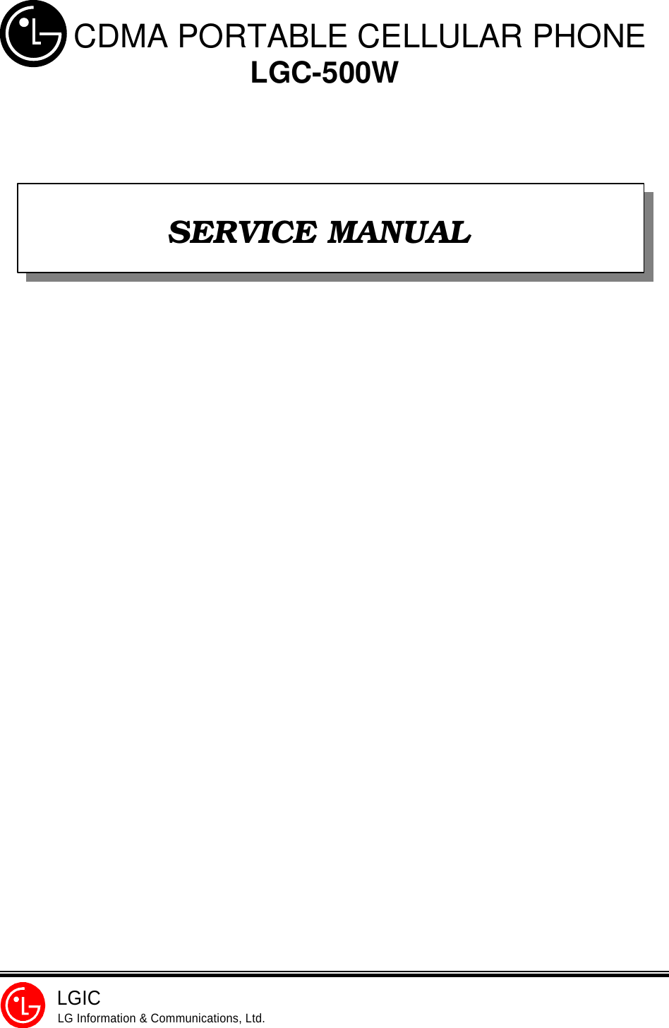
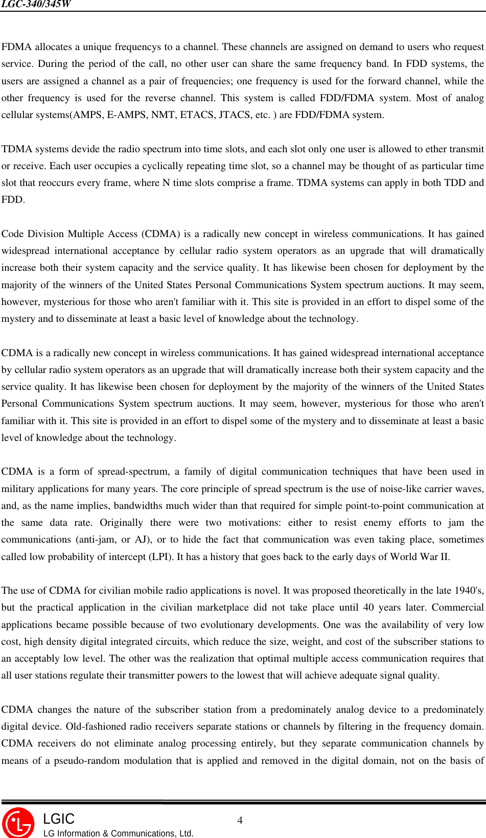
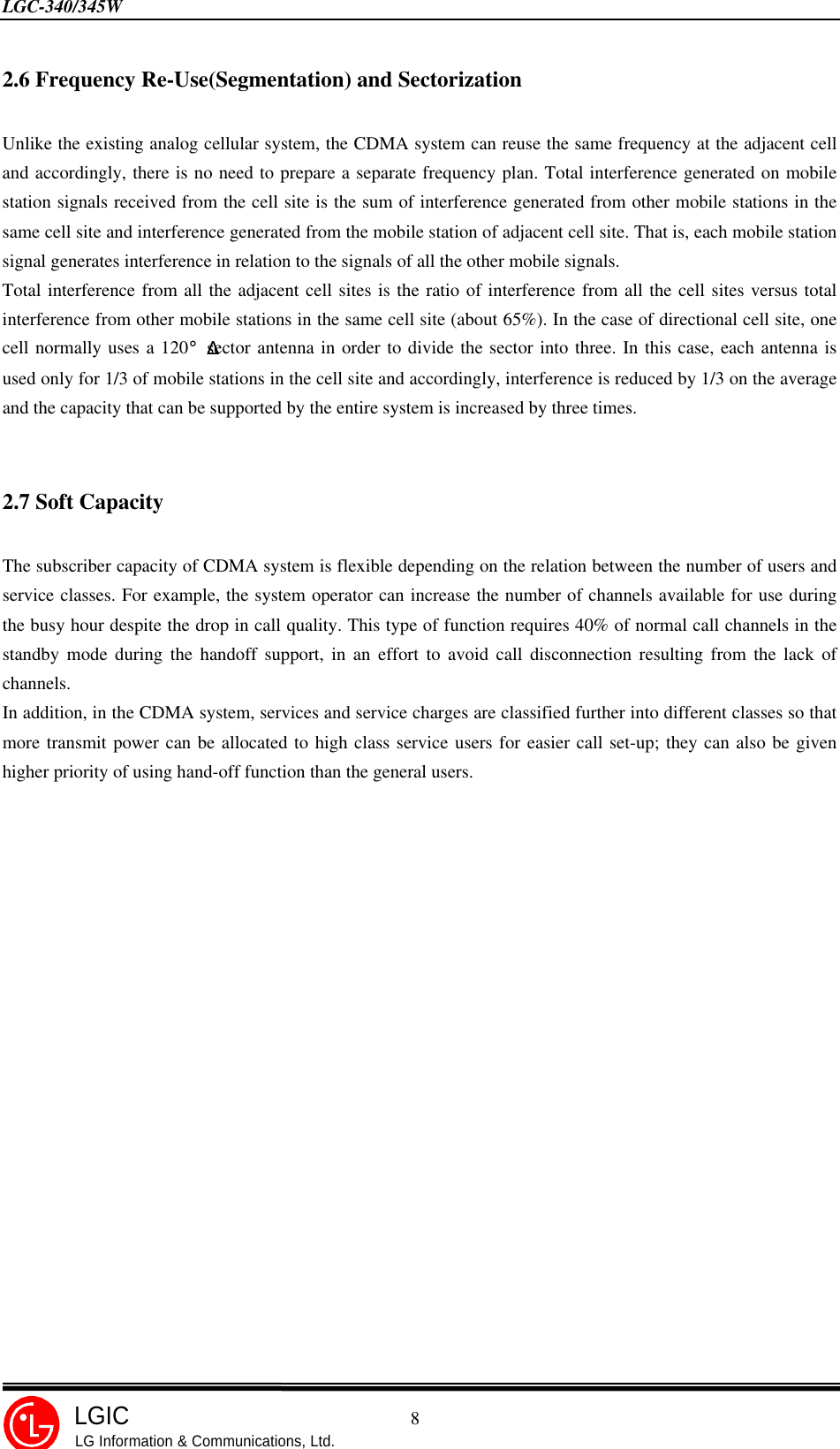
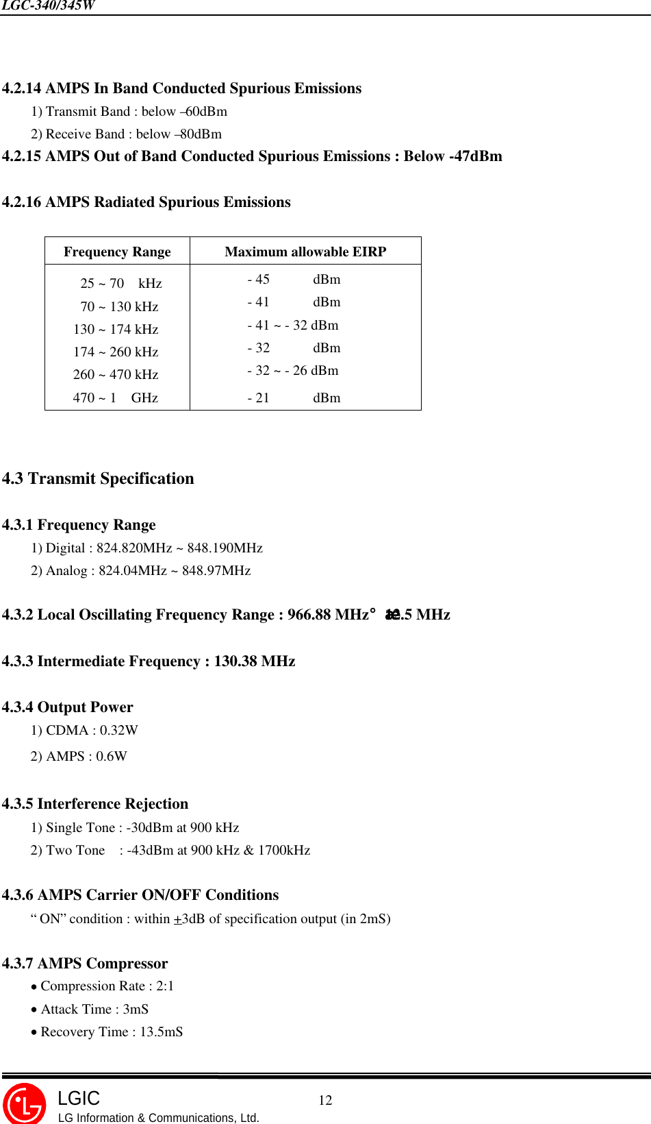
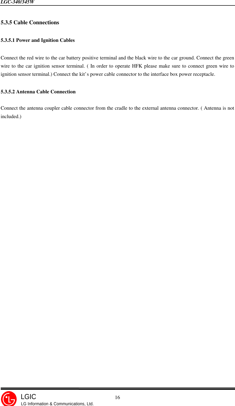
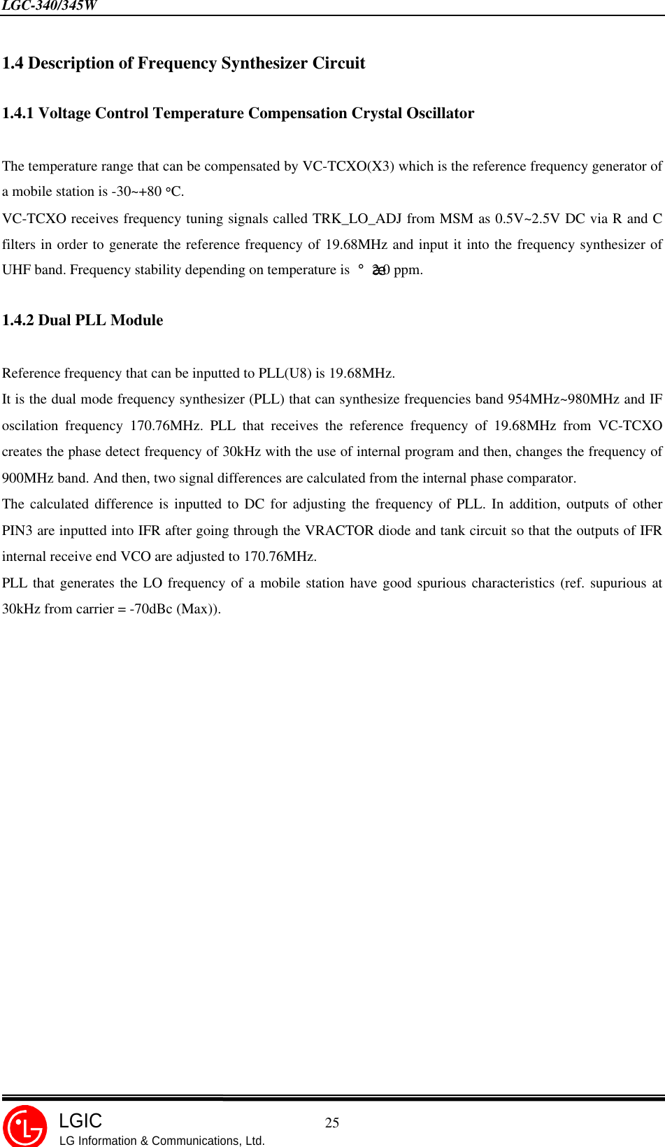
![LGC-340/345W 19LGICLG Information & Communications, Ltd.1. RF Transmit/Receive Part1.1 OverviewThe RF transmit/receive part employs the Super-Heterodyne system. The transmit/receive frequency isrespectively 824.04~848.97 MHz and 869.04~893.97 MHz and the block diagram is shown in Appendix 4.RF signals received through the antenna are fed into the low noise amplifier (LNA) through the duplexer. Then,they are combined with the signals of local oscillator (VCO) at the frequency mixer in order to createintermediate frequency (IF).Intermediate frequency created is sent out to each bandpass filter (BPF) through the FM (Analog) or CDMA(Digital) path and then, fed into IFR (RX IF BASEBAND converter), signals are auto gain controlled and, arechanged into baseband signals.These signals are then, changed into digital signals by the analog/digital converter (ADC, A/D Converter) andthen, sent to the MSM (Mobile Station Modem) of the digital circuit part. Then, they are demodulated by themodulator/demodulator.In the case of transmission, IFT receives modulated digital signals from the MSM of the digital circuit and then,changes them into analog signals by the digital/analog converter (DAC, D/A Converter) in order to createbaseband signals. Created baseband signals are changed into IF signals by IFT and then, are auto gain controlled.IF signals that have been fed are mixed with the signals of VCO and changed into the RF signals and amplifiedwith dynamic range.They are amplified at the Power AMP. Finally, they are sent out to the cell site via the antenna after goingthrough the isolator and duplexer.Block Diagram of RFLocal circuitPowerAMPUpmixerDriveAMPLNADownMixerIFAMPDuplexerSAWFilterTX RFSAWFilterRX RFSAWFilterPLLVCO VC -TcxoRF IFTXTankIFT3000RXTank IFR3000CDMA IFSAW FilterDFM IFSAW Filter19.68M Hz19.68M HzPA_ON TX_AGC_ADJLNA_Range SYNTH_LOCKIsolator[Figure 1-1] Block Diagram of RF Transmit/Receive Part CHAPTER 3. Circuit Description](https://usermanual.wiki/LG-ELECTRONICS/LGC500W.Service-Manual/User-Guide-58543-Page-20.png)
![LGC-340/345W 22LGICLG Information & Communications, Ltd.CDMA analog I and Q baseband components are converted to digital signals by 2 4-bit ADCs.The ADCs outputa new 4-bit parallel digital value on each rising edge of the ADCs synchronous clock input signal,CHIP×8.The CHIP×8 ADC clock frequency of 9.8304 MHz is developed in the IFR3000 by multiplying the 19.68MHzsystem crystal oscillator frequency by 512/1025.At the 2 4 bit ADCs, Q_OFFSET and I_OFFSET signals are inputted to MSM3000.These signals are very important during the digital signal processing process of receive signal paths andaccordingly, the adjustment should be made in such a way that the MSM3000 detects the difference from ADCdigital output RXID[3:0] and RXQD[3:0] and then, generates PDM (Pulse Density Modulation) signals forcompensating the variation. This PDM signal passes the single-pole RC LPF and then, is converted into DVvoltage before being inputted to the I-OFFSET and Q-OFFSET terminals of the IFR3000.1.2.4.2 FM Rx Signal PathThe Fm received signal Path is designed to accept a differential IF signal with frequency modulation extending±15kHz from the IF center frequency to form a 30Hz wide IF channel. The IF center frequency is same as theCDMA IF center frequency, 85.38MHz.The RX AGC amplifier interface with the IF subsystem of the subscriber unit. The Rx AGC either amplifiers orattenuates the received FM IF signal to provide a constant amplitude.Constant amplitude signals go through the I/Q downconverter.The AGC amplifier conditions the received IF signal to optimize between low IF output power level and highsignal intellegibility and reliability. The AGC gain is controlled by varing a DC voltage on the Vcontrol input pin.The AGC’s 90dB dynamic range is availiable over the full power supply range of the device.The IF output of the Rx AGC amplifier is separated into I-Channel and Q-channel baseband compoments anddownconverted by mixing with quadrature local oscilliator signals.The I and Q phasing of the receive section is spectrally inverted form a standard quadrature demodulator whenthe IF input signal frequency is above the IF center frequency.The I/Q down converter outputs the FM signals at baseband frequency. Low pass filtering enables the receiver toselect the desired baseband signal from the jamming effects of unwanted noise or adjacent-channel interference.FM analog I and Q baseband components are converted to digital FM(DFM) signals by two 8-bit ADCs. The FMADCs’ outputs are inputted into MSM3000 through RXIFMDATA and RXQFMDATA terminals.](https://usermanual.wiki/LG-ELECTRONICS/LGC500W.Service-Manual/User-Guide-58543-Page-23.png)
![LGC-340/345W 23LGICLG Information & Communications, Ltd.1.3 Transmit Part Circuit Description1.3.1 Description on the Internal Circuit of IFT30001.3.1.1 CDMA Tx Signal Path8 bits I and Q transmit signals are inputted into 2 DACs (Digtal to Analog Converter) from the output terminalTX_IQDATA[7:0] of the MSM 3000 through the input terminals TXD[7:0] of the IFT3000.In the signals coming out of the DACs, there are spurious frequency ingredients resulting from DAC outputtransition edge and parasite ingredients, transmit clock frequencies and harmonics which are unwanted signals.Accordingly, spurious ingredients are removed by passing the signals through LPF of passband 630kHz.Unlike the receive end, the transmit end LPF requires no OFFSET adjustment.The IFT3000 includes a programmable Tx PLL for synthesizing the TxIF frequency.The TxVCO oscillates at twice the TxIF frequency. The 260.76MHz created in the IFT3000’s internal VCO aredivided by half into frequency 130.38MHz having the phase difference of 90 degrees.Analog I and Q baseband components are mixed in quadrature with the Tx IF frequency and added again togenerate a modulated waveform centered at 130.38MHz IF frequency.A temperature-compensated Tx AGC amplifier with 84dB gain range is included in the IFT3000. The transmitoutput power level of the subscriber unit is directly controlled by varying the gain of this Tx AGC amplifier.APDM output from the MSM3000 ‘s TX_AGC_ADJ pin is RC low-pass filtered and turned to a DC voltage level.This voltage level linearly controls the gain of the Tx AGC amplifier.1.3.1.2 FM Tx Signal PathOnce 8 bits digital transmit signals are transferred to IFT3000 from MSM3000.They are inputted into LPF through DAC for Q signal, which is one of two DACs.During this time, all the paths for the spread spectrum algorithm do not operate and accordingly, powerconsumption can be reduced. FM transmit signals that pass through LPF are outputted after being changed intothe FM modulation signal FM_MODE of band 30KHz.The use of Tx AGC is same as the CDMA Tx signal path.1.3.2 Upconverter and Drive AMPUpconverter(U13) is made up of a mixer part and a amplifier part. The mixer part is used to receive double-balanced OUT+ and OUT- of IFT3000 and mixes the output of Dual PLL Module with UHF output signal.Upconverter’s output operation range is 800MHz~960MHz (RF frequency) and has the conversion gain of 5 dB.In addition, the suppression of spurious signals which are unwanted noise(885kHz offset) is about -50 dBc when](https://usermanual.wiki/LG-ELECTRONICS/LGC500W.Service-Manual/User-Guide-58543-Page-24.png)
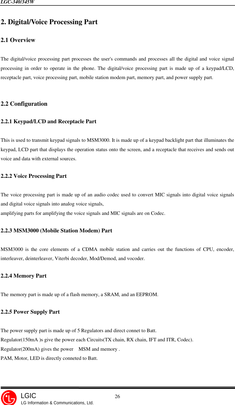
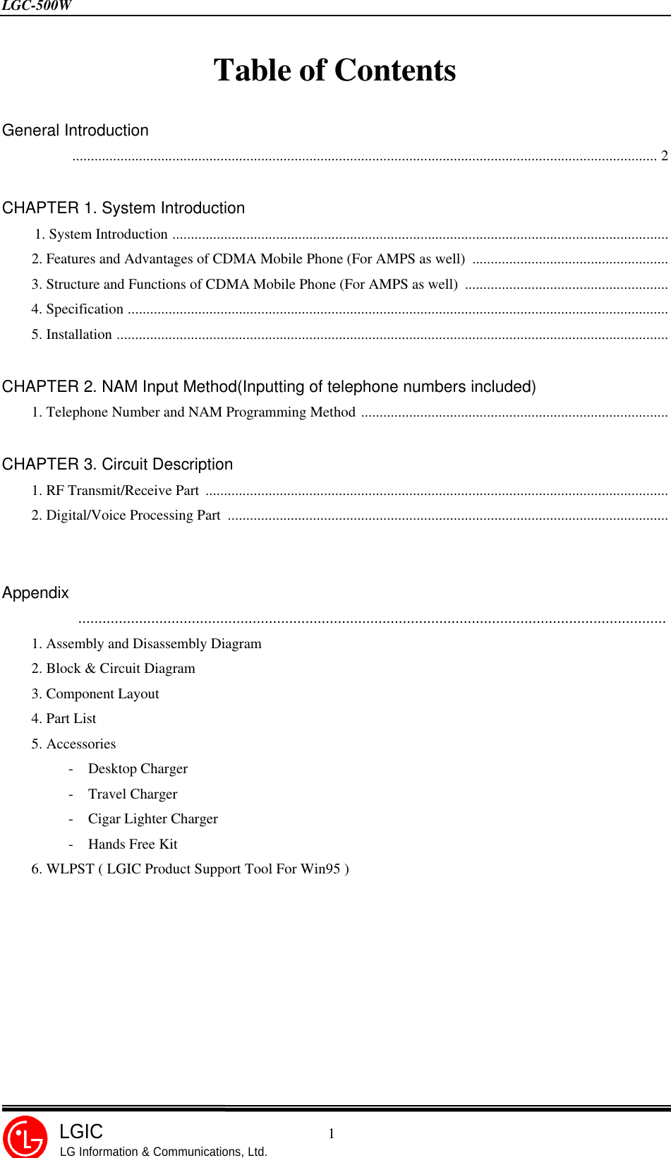
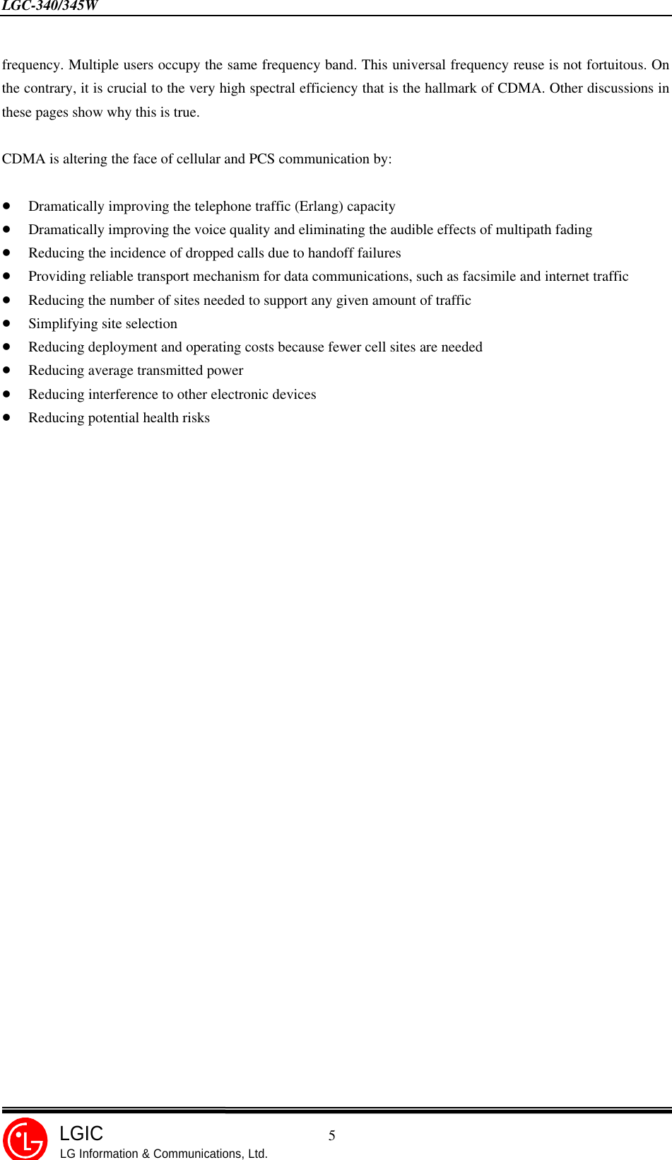
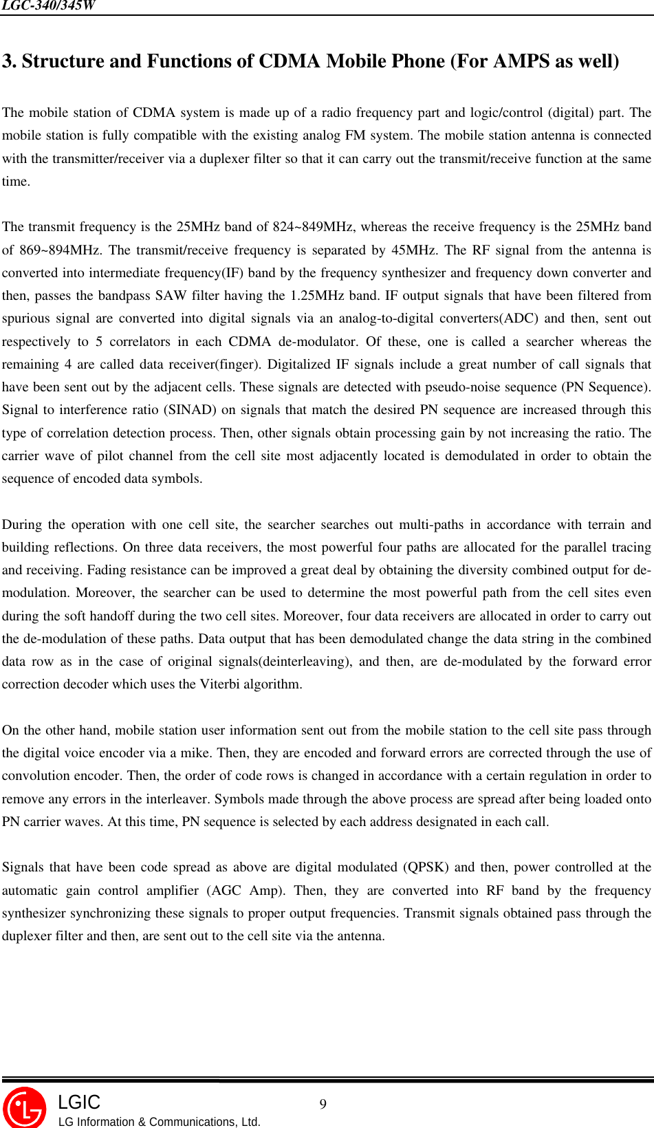
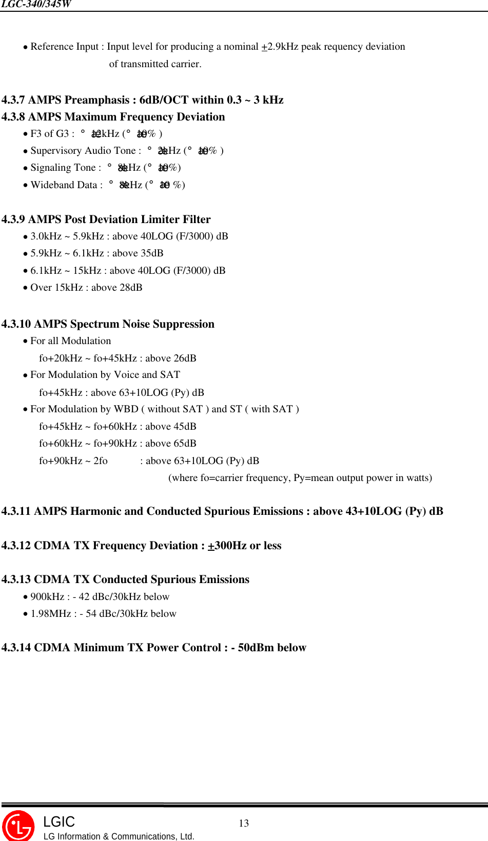
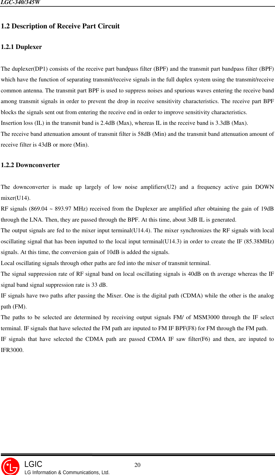
![LGC-340/345W 27LGICLG Information & Communications, Ltd.2.3 Circuit Description[Figure 2-1] Block Diagram of Digital/Voice Processing Part2.3.1 Keypad/LCD and Receptacle PartOnce the keypad is pressed, the key signals are sent out to MSM3000(U16) for processing. In addition, when thekey is pressed, the keypad lights up through the use of 16 LEDs. The status and operation of a mobile station aredisplayed on the screen for the user with the characters and icons on the LCD.Receptacle(CON3) exchanges audio signals and data with external sources and then, receives power from thebattery or external batteries.2.3.2 Audio Processing PartMIC signals are inputted into the audio codec, and amplified with programmable gain(2dB step), and convertedinto digital signals(PCM). Then, they are inputted into MSM3000.In addition, digital audio signals(PCM) outputted from MSM3000 are converted into analog signals after goingthrough the audio codec. These signals are amplified with programmable gain on codec’s internal AMP andtransferred to the ear piece. Then, the signals of ringer activate the ringer is generated in MSM3000 and drive theringer circuit(Q10, Q11).AT53BV164Digital PartMSM 3000memoryFlash ROMEEPROMCODECKey PadReceptacleLCDMICBuzzerEarPiecePower3.0 v3.0 v](https://usermanual.wiki/LG-ELECTRONICS/LGC500W.Service-Manual/User-Guide-58543-Page-28.png)