LG ELECTRONICS LGC800W SINGLE-BAND CELLULAR CDMA PHONE User Manual SVC Manual 800W
LG Electronics, Inc. SINGLE-BAND CELLULAR CDMA PHONE SVC Manual 800W
UserManual.wiki
>
LG ELECTRONICS
>
LGC800W User Manual
>
Service Manual
Contents
1.
Users Manual
2.
Service Manual
Service Manual
Navigation menu
Upload a User Manual
Namespaces
Wiki Guide
HTML
PDF
Info
Views
User Manual
Discussion / Help
Navigation
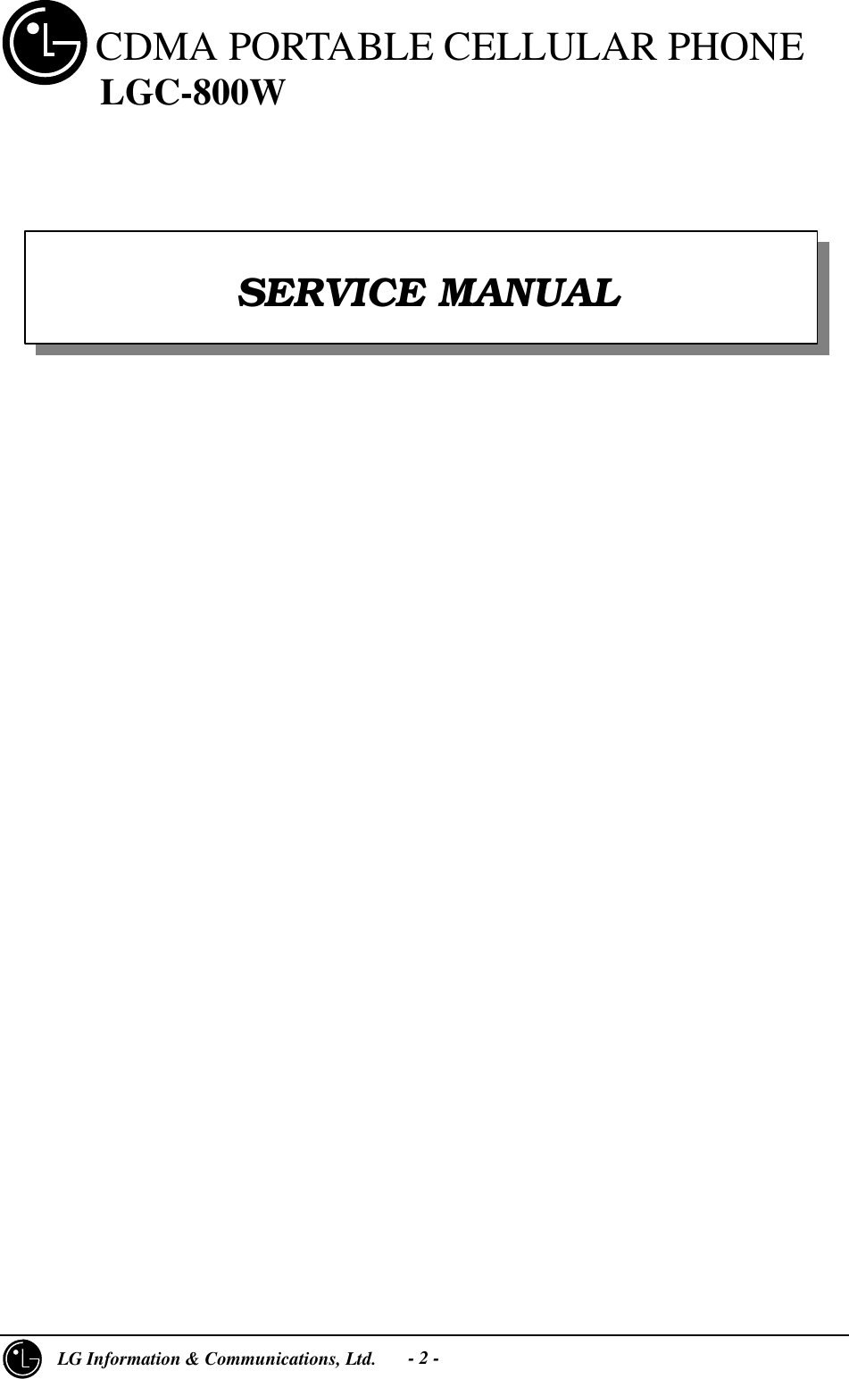
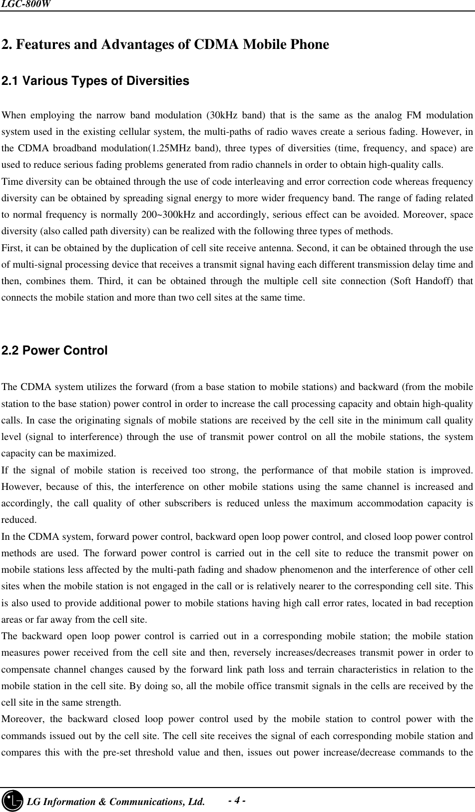
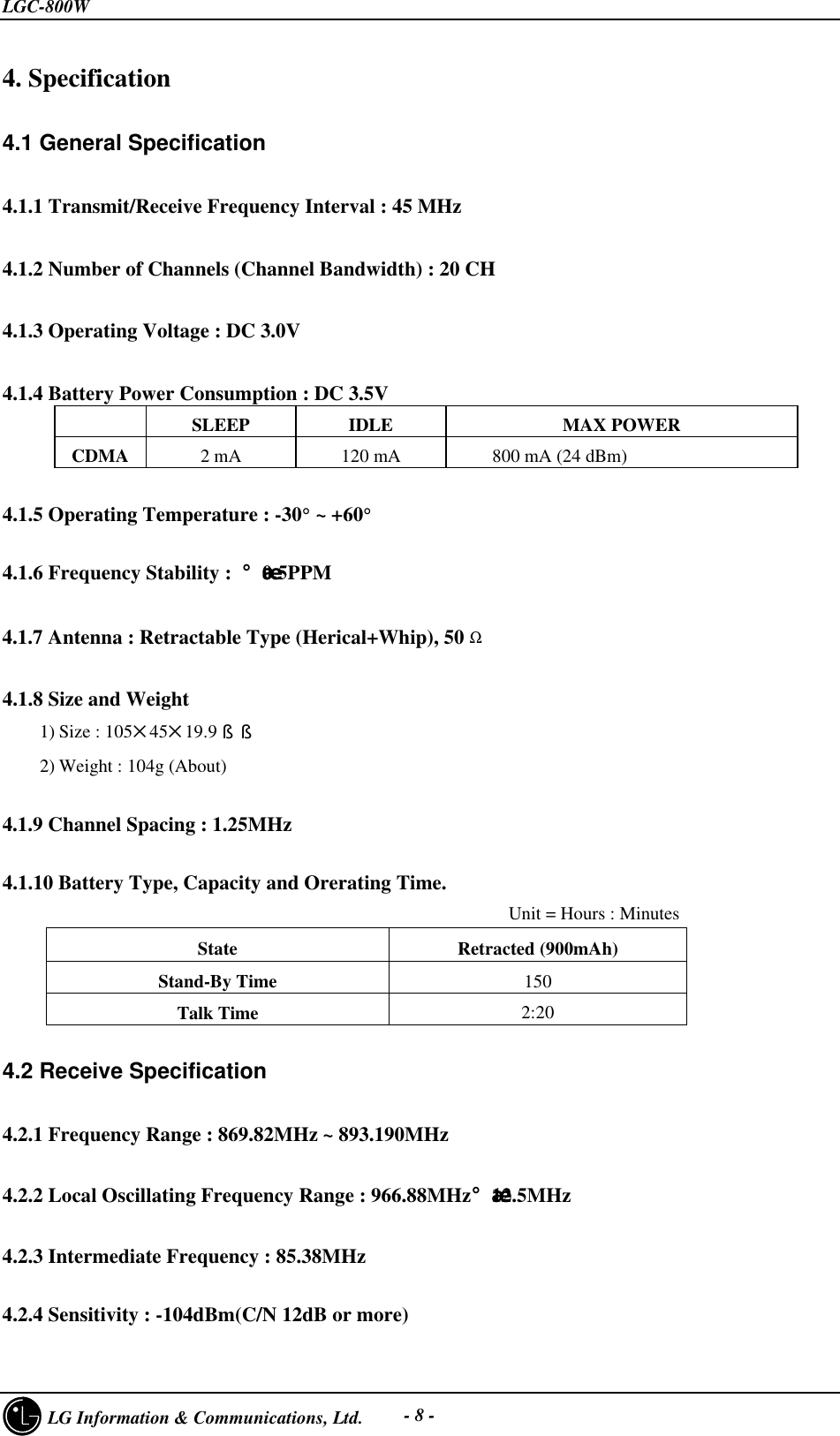
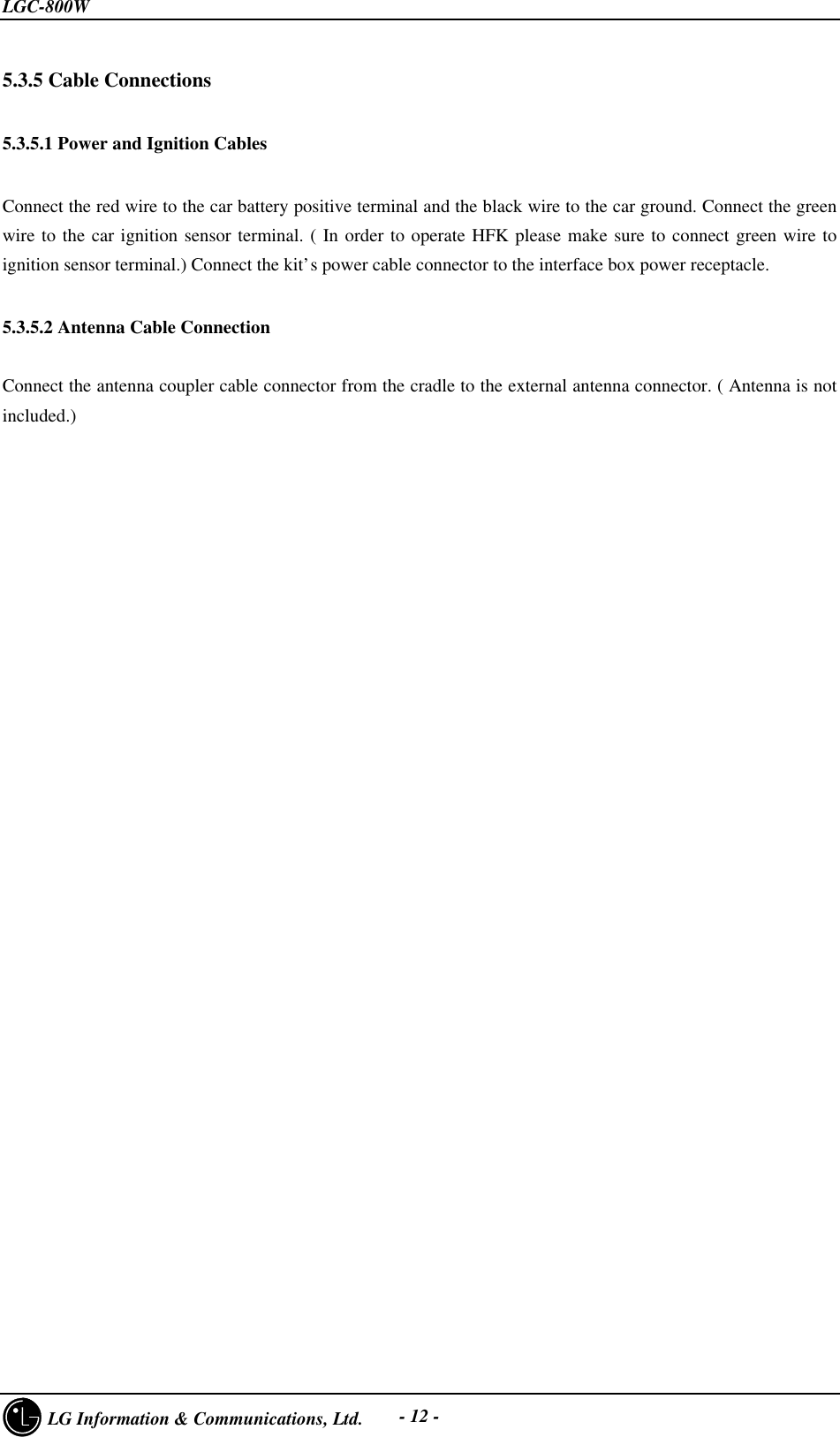
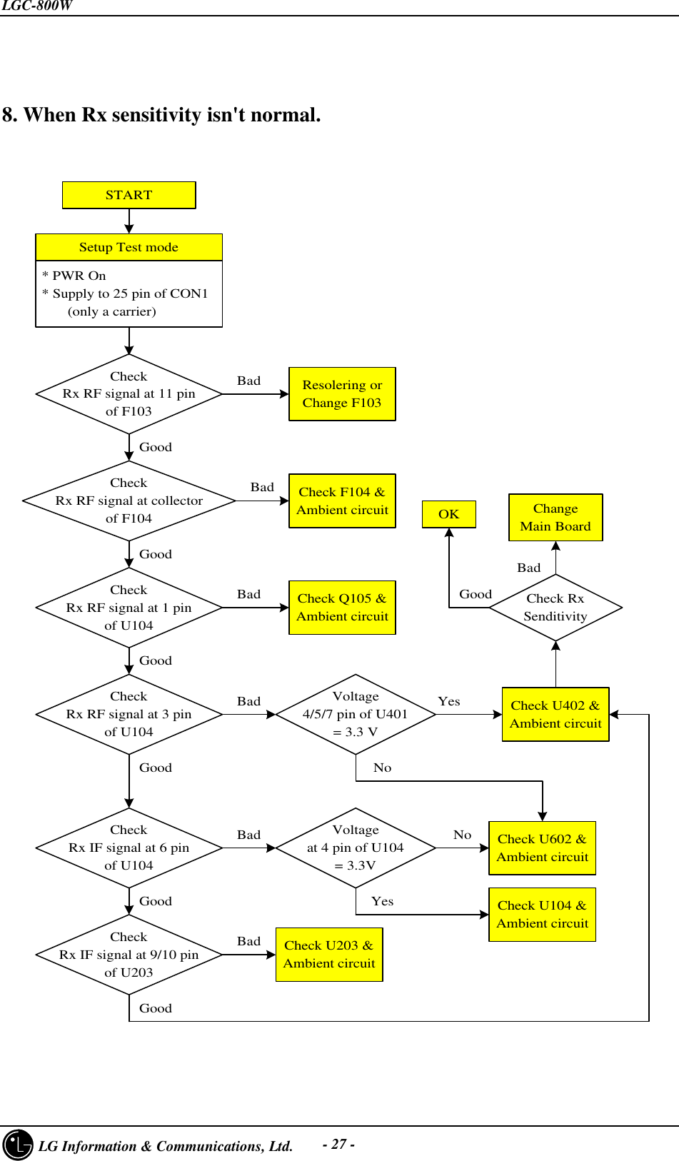
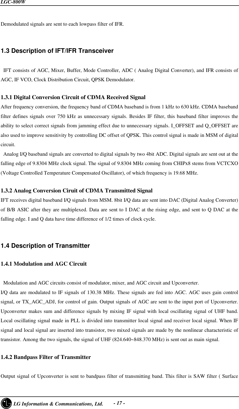
![LGC-800W LG Information & Communications, Ltd. - 13 -1. Telephone Number Inputting MethodTelephone numbers can be inputted as follows in LGC-800W. • Press MENU+0 and then, press the password made up of six digits(Default:000000). • Press 6 when the menu is displayed as illustrated on the followi type. è • NAM1 Setting Õ NAM2 Setting. • Select one NAM and then, input as shown in the following diagram (registration required from NAM1).PHONEMODEL7SLOT CYCLEINDEX2[SAVE]NAM1.PHONE NUMBER0000000000NAM1.NAMEPOWER 017[SAVE][SAVE][SAVE] CHAPTER 2. NAM Input Method (Inputting of telephone numbers included)1 : Serv Mode ç2 : Pref. Mode 1 : Short NAM ç2 : Ext. NAM](https://usermanual.wiki/LG-ELECTRONICS/LGC800W.Service-Manual/User-Guide-42103-Page-15.png)
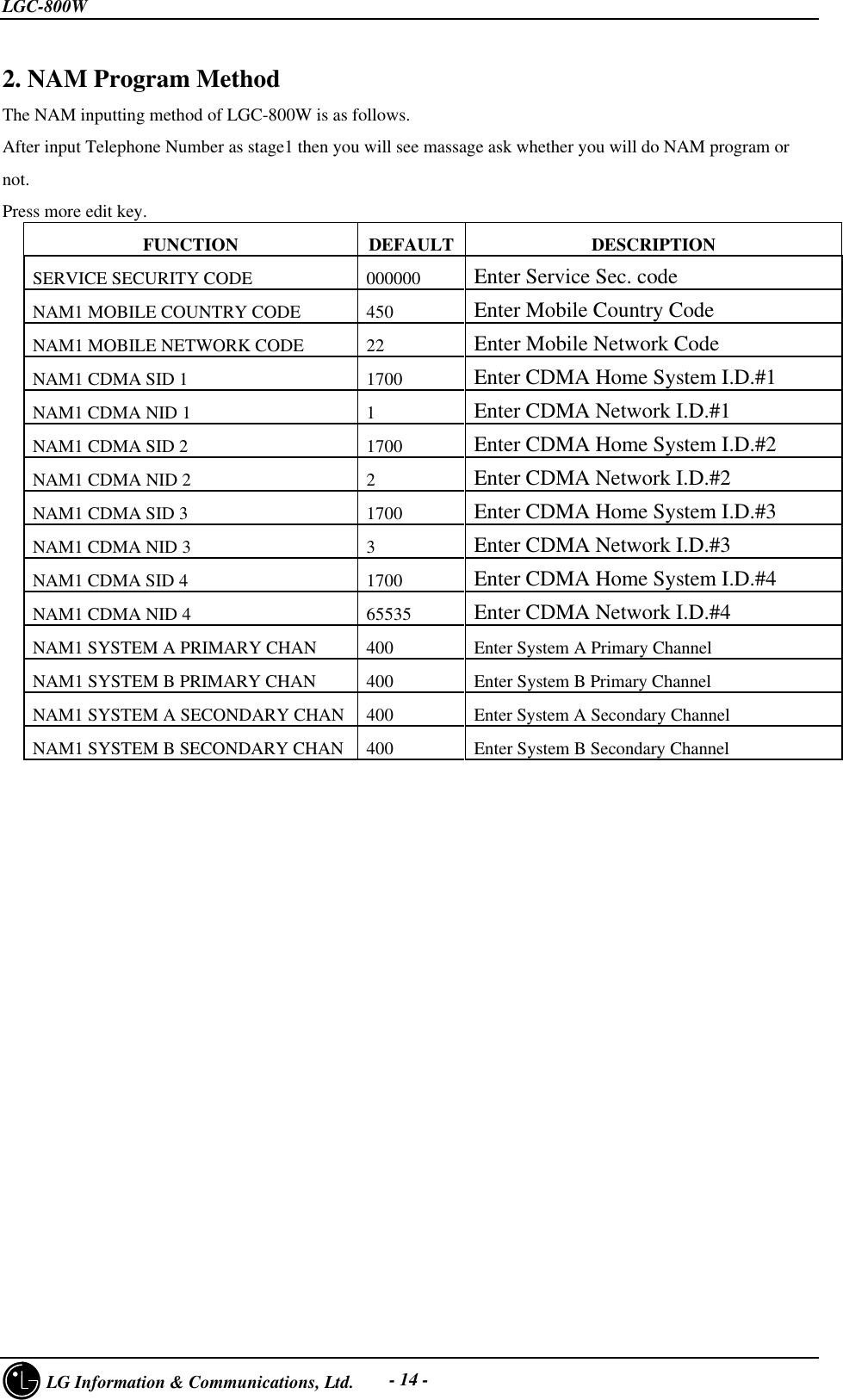
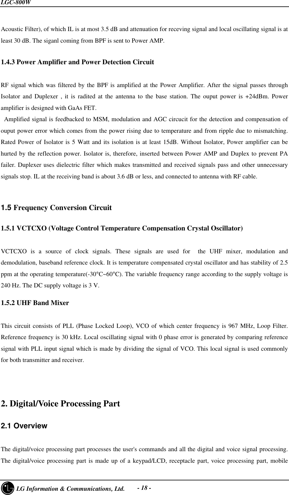
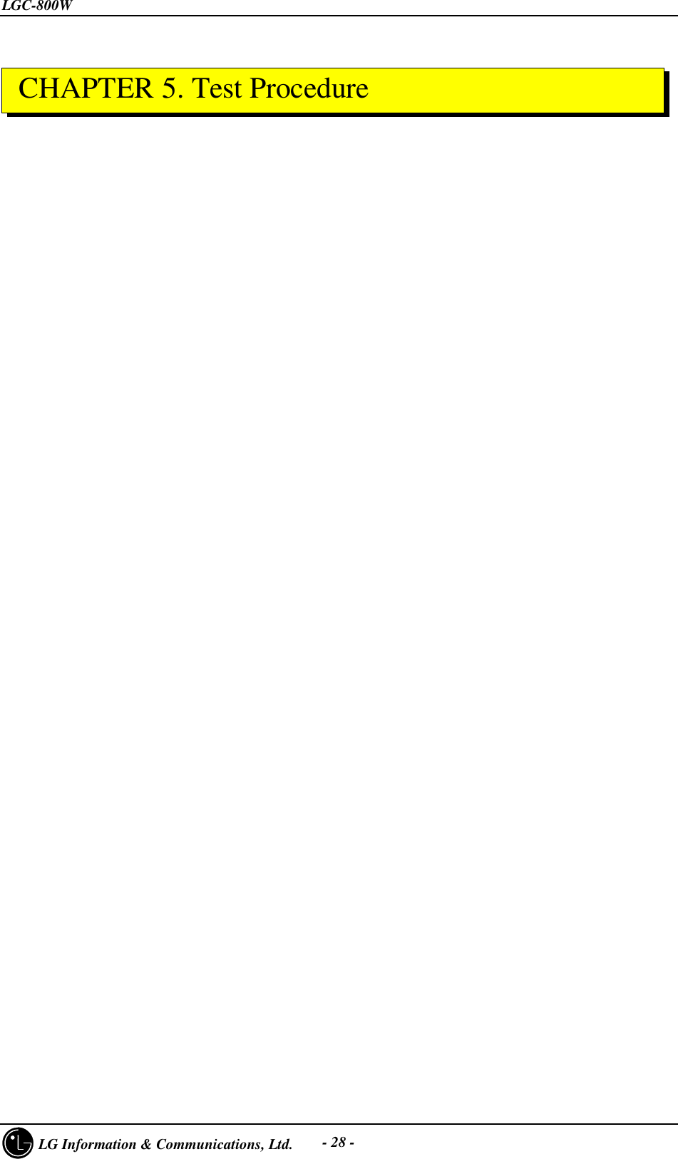
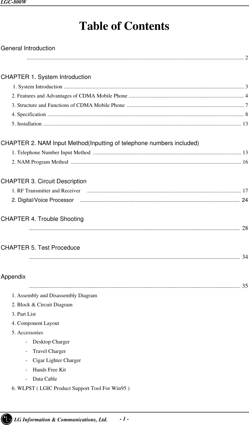
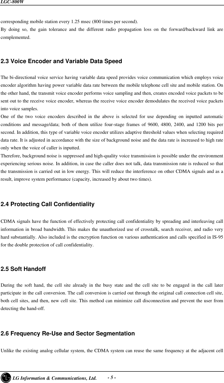
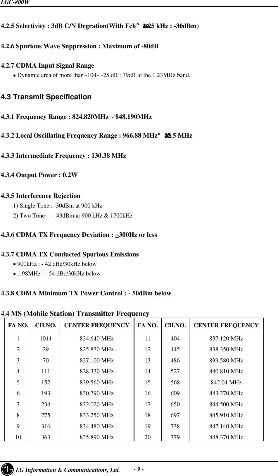
![LGC-800W LG Information & Communications, Ltd. - 22 -1. When power isn't "Turn On".STARTRecharge Batt.Batt. Volt< 3.6VYesNo Change U703 Voltage at16 pin of U703< 3.6VNoYes Voltage at9 pin of U703< 3.3VChange U605 Voltage at5 pin of U605< 3.3VChange Sub. BoardTurn On YesNoChange Main BoardChangeOld Sub. BoardYesYesNoYesNo2. When LCD isn't displayed.STARTRefer to [1]Circuit to supplypower nominal?YesNo Check pins of con972orReconnect con972LCD supplied power NoYesGoodLCD display?YesNoChange LCD CHAPTER 4. Trouble Shooting](https://usermanual.wiki/LG-ELECTRONICS/LGC800W.Service-Manual/User-Guide-42103-Page-24.png)
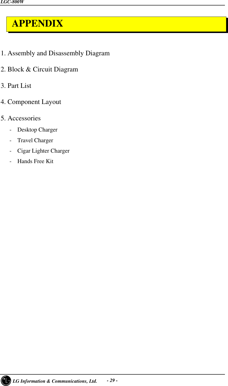
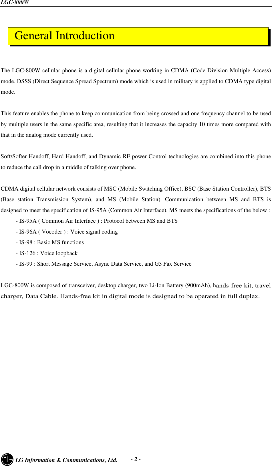
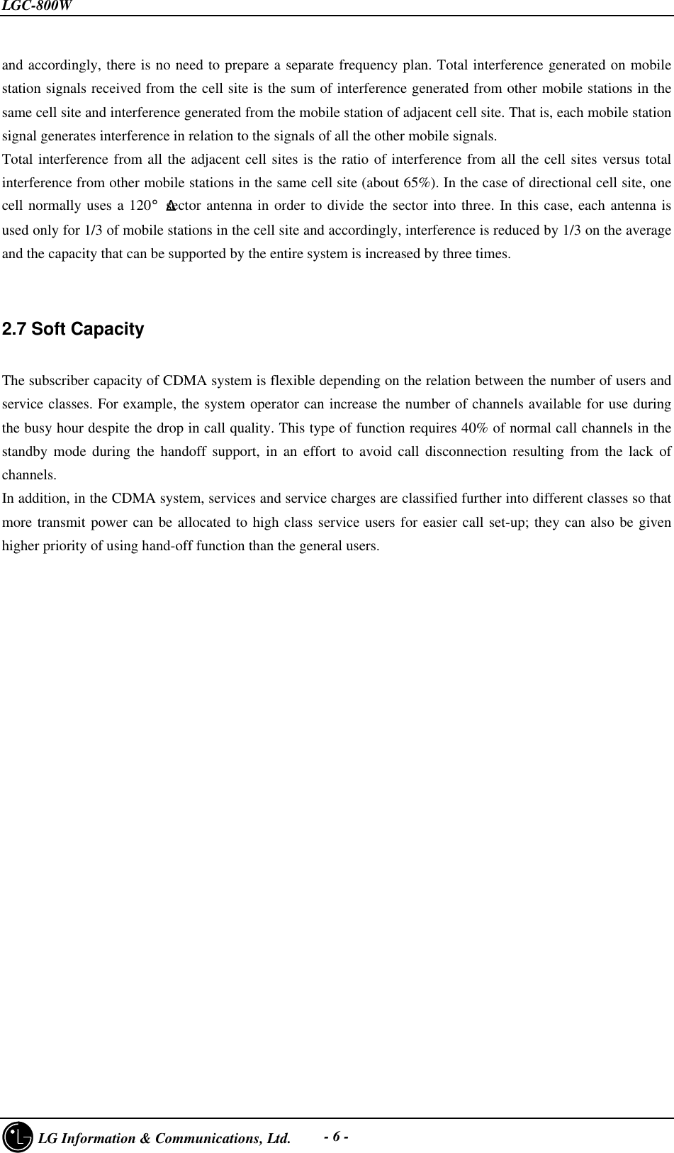
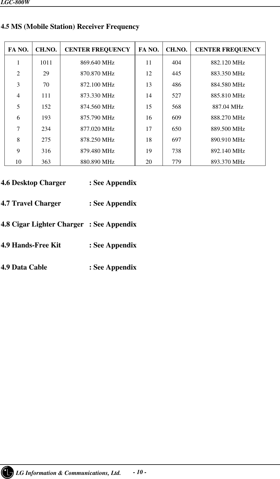
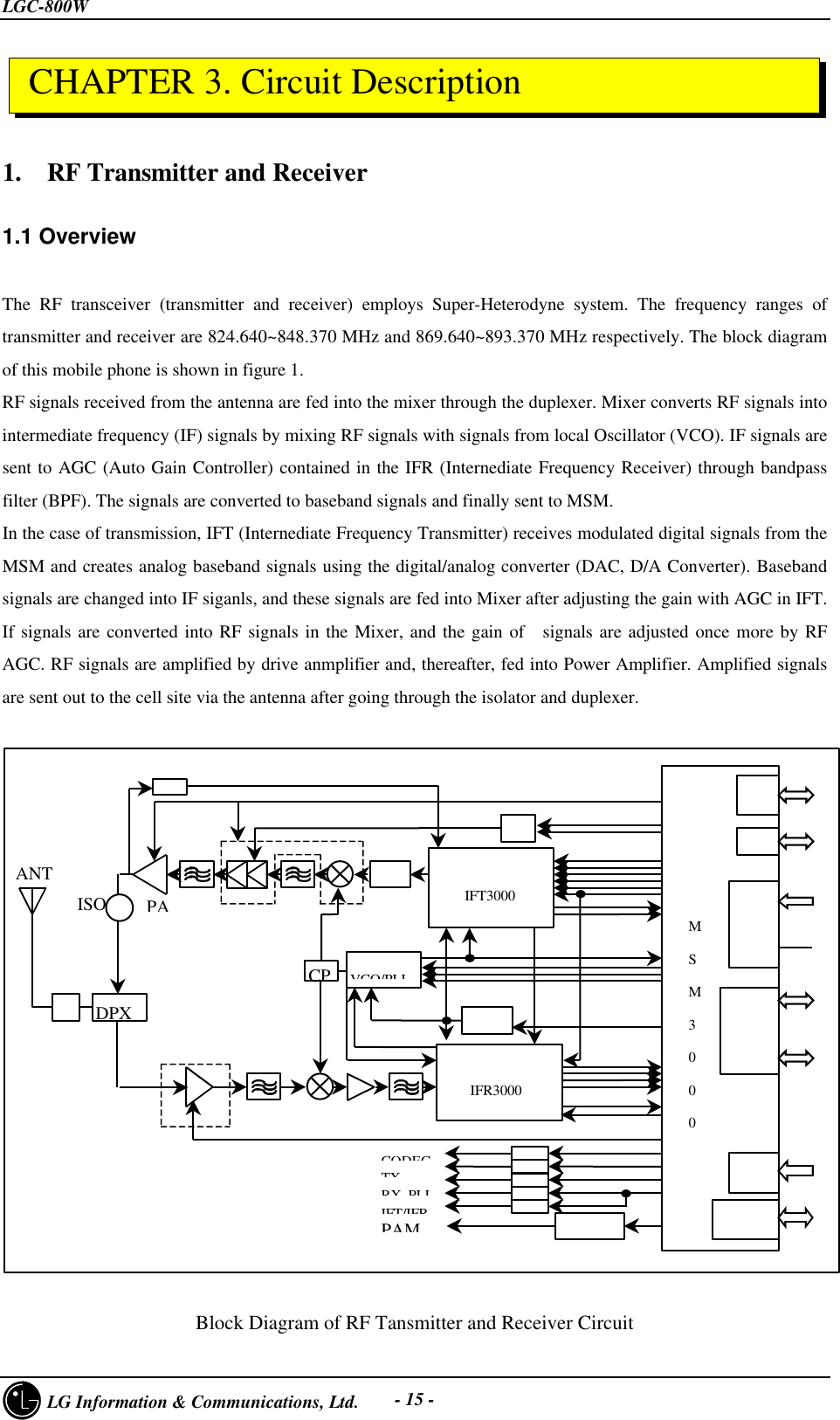
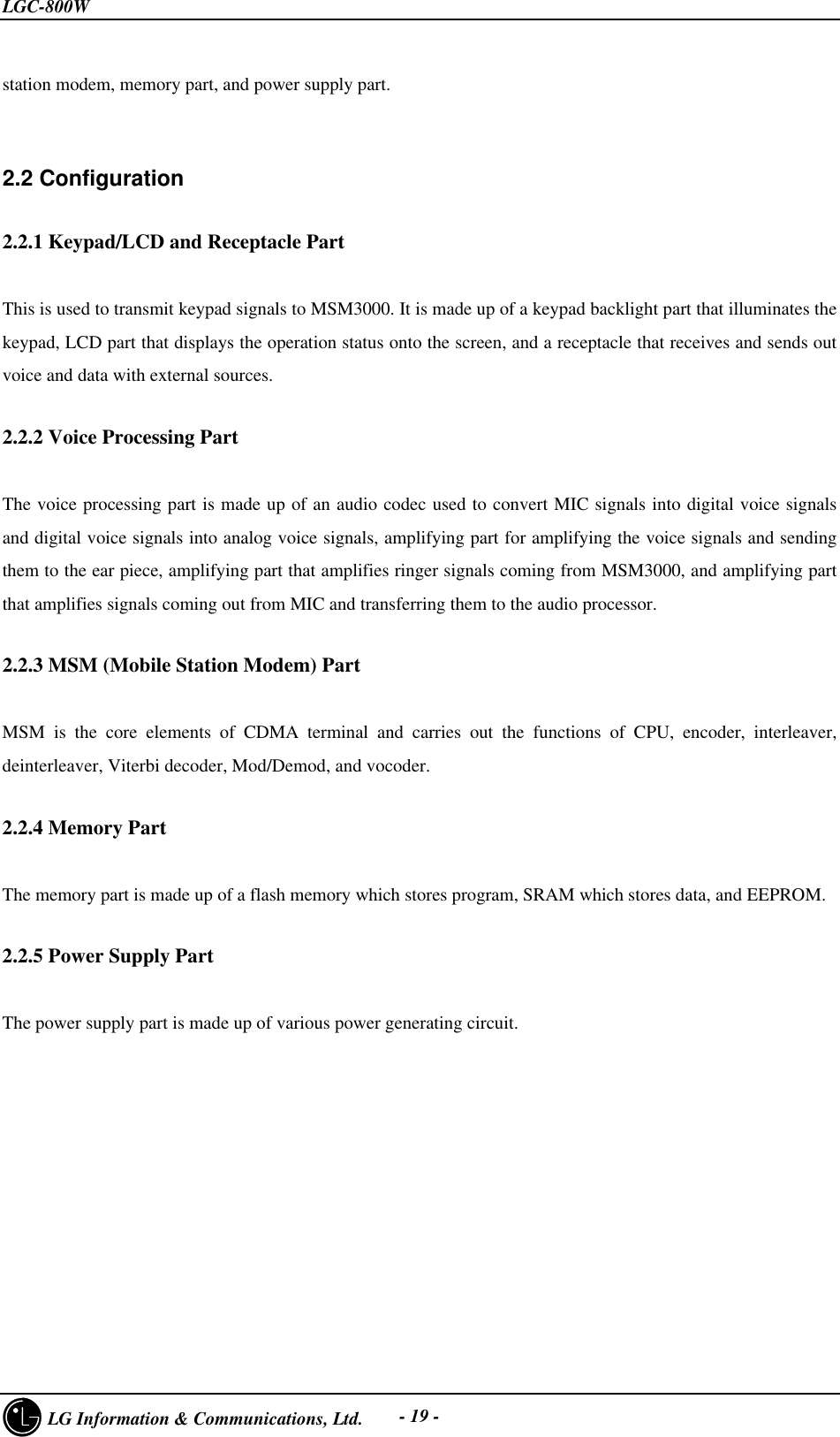
![LGC-800W LG Information & Communications, Ltd. - 26 -Voltage at3 pin of Q108 = 3.6VNoYesCheck U701BRF freq.appear at 1 pin of Q108?NoYes Change Q108RF freq.appear at 2 pin of F101?NoYesChange F101Voltage at5 pin of U601 = 3.6VNo Change U601YesNoYesVoltage at1 pin of U601 = 5VRefer to [1]DVoltage at4/8 pin of PWR1 = 5VNoYesCRF freq.appear at 3 pin of U102?NoYesChange PWR1 or PWR detect circuitNoYesChange U102RF freq.appear at 9 pin of F103?Voltage at4 pin of Q101 = 5VYesDChange Q101NoYesChange F103Change CON1RF freq.appear at 25 pin of CON1?](https://usermanual.wiki/LG-ELECTRONICS/LGC800W.Service-Manual/User-Guide-42103-Page-28.png)