LG Electronics USA 118AN 802.11abgn Video / Audio Transmitter User Manual UPLINK TX MESSAGE MECHANISM PROPOSAL
LG Electronics USA 802.11abgn Video / Audio Transmitter UPLINK TX MESSAGE MECHANISM PROPOSAL
Users Manual


1 Specification
Product Name Wireless Full HD Video/Audio Receiver
Model Number WMDA-118AN
Host Interface HDMI
Chipset solution MCU STM32F105
MAC/BBP Amimon AMN2220
RF Amimon AMN3210
Memory 4Mbit Flash
Switch Reset Button x 1
Dimensions PCB 140 x 70 (mm)
LED MAC (Green)
Operating Voltage 24V/20V/17V +/- 5%
Current
consumption 8W maximum
Antenna
PIFA Type antenna; Peak Gain:3.5 dBi
One antenna for Transmitter & Receiver
Four antennas for Receiver
One antenna for DFS Only
Frequency Band 5.15~5.35, 5.47~5.725, 5.725~5.825 (GHz)
Depends on the country region
Channel Bandwidth 40MHz
Modulation Orthogonal Frequency Division Multiplexing (OFDM)
Network mode Uni-cast
DFS Support Low-end DFS without additional RF Chain
High-end DFS with additional RF Chain allowing to monitor additional
DFS channel and immediate switch in case of radar detection
Transmit Power 13 +/- 1.5 dBm
SNR > 22 dB @ Pin~ -50 dBm
PSNR > 37 dB @ Pin~ -50 dBm
Message Error < 5 packet @ Pin~ -50 dBm
Video block error < 10 @ Pin~ -50 dBm
Operating Range 10 ~15 meter Indoor. The transmission quality varies in the system
board and surrounding environment.
Control connector Control connector (1 port)
Temperature
Range 0 ~ 40°C (Operating), -20~80°C (Storage)
Page 2 of 11 Confidential
2 Hardware involved
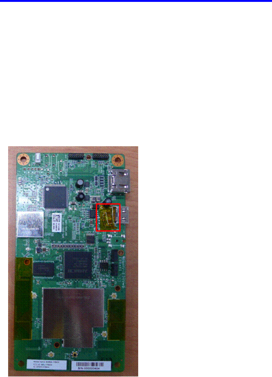
2.1 WMDA-118AN Module
The following figure shows the RX board, which has only one transmitting antenna
(marked ANT3).
The board has UART port located on the top of the board (marked J1) for
communication of the Baseband chipset (marked U2). The board has a UART port
located on the Top of the board (marked J5) for communication of the MCU chipset
(marked U28)
The board has a Power connector located on the top of the board (marked J3) for the 17
~24V power supply.
Figure 1: WMDA-118AN board
Page 3 of 11 Confidential

2.2 Product Main Features
WMDA-118AN Module :
o HDMI A/V signal output via HDMI cable.
o HDMI Receiver chipset (SiI9134).
o Supports 1080p/60 video resolution.
o HDMI v1.3 supports.
o Supports DFS.
o Amimon's 2ND generation 1080P chipsets. (AMN2220, AMN3120)
o RF Antenna use printed pattern.
o Supports 5GHz MIMO compatibility (World band 4.9GHz - 5.9GHz)
o Supports 20MHz channel bandwidth for wireless link setup
o Supports 40MHz channel bandwidth for AV data transmit
o Supports one downlink direct-conversion transmitter.
o Supports five uplink direct-conversions receiver
o IR Receiver function is bypass mode support.
o IR Receiver micro-controller chipset.
o Multi Layer PCB (6-Layer)
o 140 x 70 x 13.5 mm
2.3 Major Components
Receiver:
AMN3210 RF IC Receiver. (U15)
40MHz 3225 SMD crystal. (Y1)
AMN2220 Base Band IC Receiver. (U2)
64Mbit DDR-2 200MHz memory. (U3)
M25P40 4Mbit Flash memory. (U4)
STM32F105RB-T6 Application microcontroller. (U28)
25MHz 3225 SMD crystal. (Y2)
S3S828B IR Receiver microcontroller. (U8)
8MHz 3225 SMD crystal (Y3)
Si9134 HDMI Transmitter. (U23)
HDMI female connector. (J4)
Power, control and data connector. (J3)
Microwave Coaxial Connector without Switch SWD Type (SW1)
AL7230 2.4/5GHz 802.11a/b/g WLAN Power Amplifier (U33)
24V/20V/17V Power supply voltage.
Page 4 of 11 Confidential
2.4 Interfaces
A/V Interfaces 1 x HDMI v1.3 Output
Control I/F I2C – Application microcontroller
SPI – Amimon baseband
UART – IR Receiver microcontroller
Debug UART
External Power 17 ~ 24V
Maintenance For development phase - Firmware Update Header
connector
Maintenance For development phase - JTAG debugging Header
connector
Maintenance For development phase - IR Receiver microcontroller
download Test Point
Figure 2: WMD-118AN Interface
Page 5 of 11 Confidential
2.5 Connector Pin-out (J3)
# Signal In/Out
1 VCC 24V/20V/17V
2 VCC 24V/20V/17V
3 VCC 24V/20V/17V
4 VCC 24V/20V/17V
5 VCC 24V/20V/17V
6 VCC 24V/20V/17V
7 DETECT Connect to pull down register 3.3K (From Amimon to TV)
8 WIRELESS_INT Connect to App uC (From Amimon to TV)
9 GND Ground
10 RESET_IN Connect to App uC (From TV to Amimon)
11 GND Ground
12 I2C_SCL Connect to App uC (Communications)
13 I2C_SDA Connect to App uC (Communications)
14 GND Ground
15 APP_RXD Connect to Application micro-controller (Debug)
16 APP_TXD Connect to Application micro-controller (Debug)
17 GND Ground
18 IR_TV_IN From TV Main board to IR Blaster micro-controller
19 DP Connected to App micro-controller (F/W update)
20 DM Connected to App micro-controller (F/W update)
Page 6 of 11 Confidential
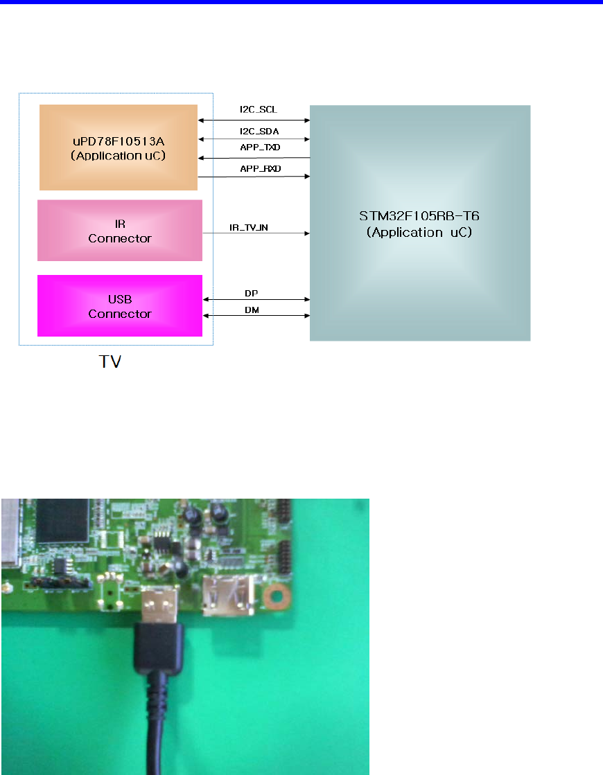
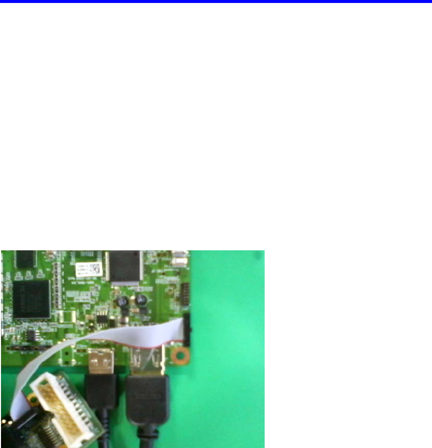
2.6 Control signal
2.7 Power Supply
Input: 17 ~24V for Rx
Figure 3: Control Cable connection Method
Page 7 of 11 Confidential
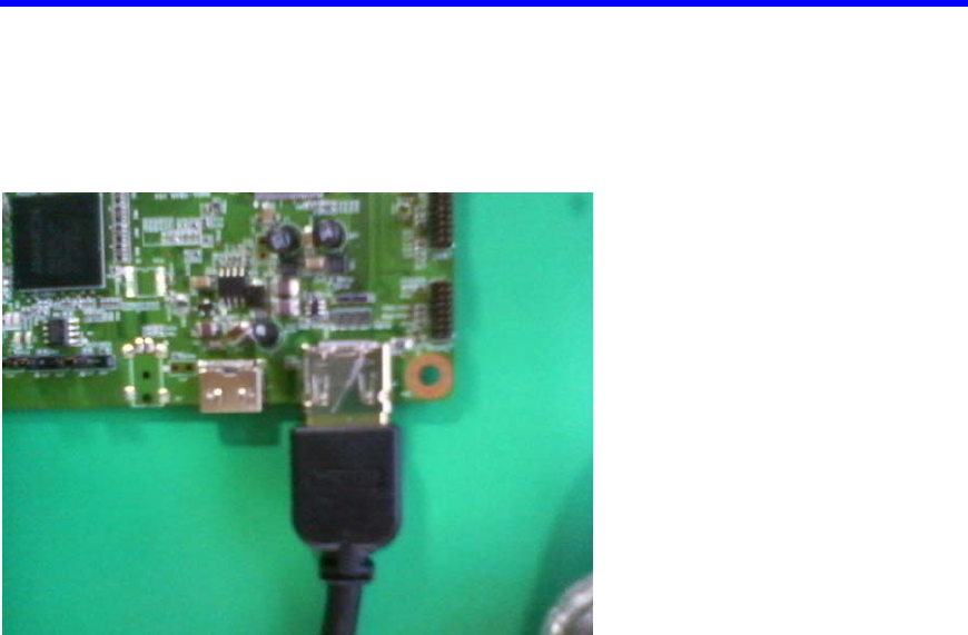
2.8 HDMI connector (J4)
Figure 4: HDMI Cable connection Method
Page 8 of 11 Confidential
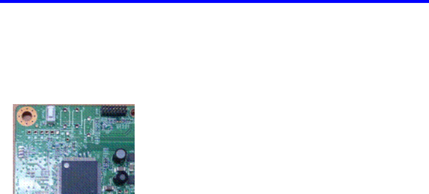
2.9 Reset Switch
The WMDA-118AN module is operating reset function.
SW2: Reset
Figure 5: Reset switch location
2.10 PC computer with a USB port
The PC should be installed with:
1. Java UART application
2. Scripts that activate Gemtek TX /Gemtek RX for a transmitting mode via UART
communication (supplied by Amimon).
Page 9 of 11 Confidential
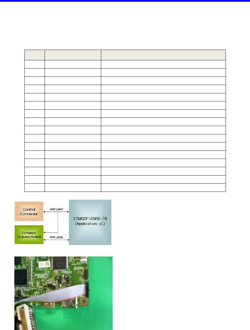
2.11 Firmware Update Header (J5)
# Signal Direction
1 VCC 3.3v, From Amimon
2 VCC 3.3v, From Amimon
3 GND
4 APP_RST Reset
5 APP_TRST JTAG functionality to Microcontroller
6 GND
7 TDI JTAG functionality to Microcontroller
8 APP_TXD Connect to Microcontroller
9 GND
10 APP_RXD Connect to Microcontroller
11 APP_TMS JTAG functionality to Microcontroller
12 APP_RTCK
13 APP_TCK JTAG functionality to Microcontroller
14 APP_TDO JTAG functionality from Microcontroller
15 GND Ground
16 GND Ground
Figure 6: UART Cable connection Method
Page 10 of 11 Confidential
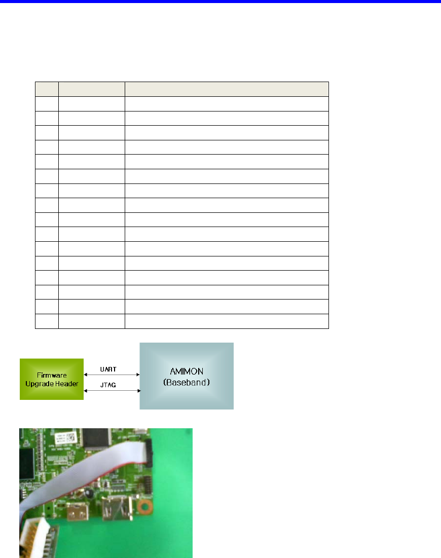
2.12 JTAG Debug Header (J1)
# Signal Direction
1 VCC 3.3v, From Amimon
2 VCC 3.3v, From Amimon
3 GND Ground
4 N.C.
5 TRST JTAG functionality to Amimon
6 GND Ground
7 TDI JTAG functionality to Amimon
8 UART_TX Connect to MAC uC (communications)
9 GND Ground
10 UART_RX Connect to MAC uC (communications)
11 TMS JTAG functionality to Amimon
12 N.C.
13 TCK JTAG functionality to Amimon
14 TDO JTAG functionality from Amimon
15 GND Ground
16 GND
Figure 7: UART Cable connection Method
Page 11 of 11 Confidential