LG Electronics USA 119AN Audio/ Video Transmitter Card User Manual
LG Electronics USA Audio/ Video Transmitter Card Users Manual
Users Manual

0
INTEGRATOR GUIDE FOR THE
WMDA-119AN
Gemtek
Writtened by Stone (YJ_SHIH) YJ_SHIH@gemtek.com.tw
#1440

- -
1
1 Specification
Product Name Wireless Full HD Video/Audio Sender
Model Number WMDA-119AN
Host Interface 60 pin LVDS
Chipset solution MCU STM32F105
MAC/BBP Amimon AMN2120
RF Amimon AMN3110
Memory 4Mbit Flash
Switch Reset Button x 1
Dimensions PCB 140 x 70 (mm)
LED Power (Yellow)
Operating Voltage 5V +/- 5%
Current
consumption 10W maximum
Antenna PIFA Type antenna; Peak Gain: 3.5 dBi
Four antenna for Transmitter
One antenna for Receiver
Frequency Band 5.15~5.35, 5.47~5.725, 5.725~5.825 (GHz)
Depends on the country region
Channel Bandwidth 40MHz
Modulation Orthogonal Frequency Division Multiplexing (OFDM)
Network mode Uni-cast
Transmit Power 10dBm @ each antenna, tolerance +/-1.5 dB
SNR > 22 dB @ Pin~ -50 dBm
PSNR > 37 dB @ Pin~ -50 dBm
Message Error < 10 packet @ Pin~ -50 dBm
Video block error < 10 @ Pin~ -50 dBm
Operating Range 10 ~15 meter Indoor. The transmission quality varies in the system
board and surrounding environment.
Temperature
Range 0 ~ 40°C (Operating), -20~80°C (Storage)
All Information presented in this document is proprietary and confidential property of Amimon LTD. Any
use of this document or any part of it, without permission is subject to be prosecuted by law.
2 Hardware involved
2.1 WMDA-119AN Module
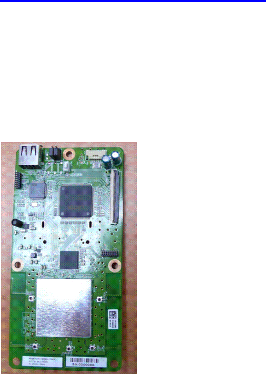
The following figure shows the TX board, which has 4 transmitting antennas. Each
antenna has a matching push connector (marked SW-1 to Sw-4) for conducted
measurements.
The board has a UART port located on the top of the board (marked J2) for
communication of the Baseband chipset (marked U1). The board has a UART port
located on the Top of the board (marked J501) for communication of the MCU chipset
(marked U501).
The board has a Power connector located on the top of the board (marked J702) for the
5V power supply.
Figure 1: WMDA-119AN board

Page 3 of 15 Confidential
2.2 Product Main Features
WMDA-119AN Module :
o A/V signals input through 60 pin LVDS cable
o Power and control input/output through 8pin cable assembly
o Supports 30bit YCbCr (4:4:4) TTL signals include HSYNC, VSYNC, DE and
DCLK.
o Supports 1080p/60 video resolution output.
o Supports standard I2S.
o HDMI v1.3 supports.
o Application micro-controller’s image update via USB memory disk.
o Amimon's 2ND generation 1080P chipsets. (AMN2120, AMN3110)
o RF Antenna use printed pattern.
o Supports 5GHz MIMO compatibility (World band 4.9 GHz – 5.9 GHz)
o Supports 20MHz channel bandwidth for wireless link setup
o Supports 40MHz channel bandwidth for AV data transmit
o Supports downlink stream video and audio through up to four RF output channels
o Supports four downlink direct-conversion transmitters.
o Supports four digital to analog converters (ADC)
o Supports downlink channel with up to 1Mbps for data and control
o Supports uplink stream data and control from one RF channel.
o Supports one uplink direct-conversion receiver.
o Supports one analog to digital converter (DAC)
o Supports uplink channel with up to 100Kbps for data and control
o Multi Layer PCB (6-Layer)
o 140 x 70 x 13.5 mm.
2.3 Major Components
AMN3110 RF IC Transmitter. (U16)
40MHz 3225 SMD crystal. (Y2)
AMN2120 Base Band IC transmitter. (U1)
M25P40 4Mbit Flash memory. (U2)
STM32F105RB-T6 Application microcontroller. (U501)
25MHz 3225 SMD crystal. (Y501)
USB connector (J502)
Control and A/V data connector (J701)
Power connector (J702)
Microwave Coaxial Connector without Switch SWD Type (SW1, SW2, SW3,
SW4)
RTC6670 2.4/5 GHz 802.11a/b/g WLAN Power Amplifier (U5, U7, U9, U11)
5V Power supply voltage
Page 4 of 15 Confidential
2.4 Interfaces
Video 2 channel LVDS
Audio 2 channel I2S
Control I/F I2C - Application microcontroller
SPI – Amimon baseband
UART – IR Transmitter microcontroller
Debug UART
External Power 5V
Maintenance For development phase - Firmware Update Header connector
Maintenance For development phase - JTAG debugging Header connector
Maintenance For development phase - USB connector
Figure 2: WMD-119AN Interface

Page 5 of 15 Confidential
2.5 Connector Pin-out (J701)
# Signal In/Out # Signal In/Out
1 GND 31 GND
2 LVDS_RA1- LVDS output 32 GND
3 LVDS_RA1+ LVDS output 33 MCLK Audio master clock
4 LVDS_RB1- LVDS output 34 SCLK Audio serial clock
5 LVDS_RB1+ LVDS output 35 I2S0 Audio data
6 LVDS_RC1- LVDS output 36 LRCLK Audio LR clock
7 LVDS_RC1+ LVDS output 37 GND
8 GND 38 SPDIF Audio SPDIF data
9 LVDS_RCLK1- LVDS clock output 39 GND
10 LVDS_RCLK1+ LVDS clock output 40 TP Test Point
11 GND 41 TP Test Point
12 LVDS_RD1- LVDS output 42 IR_RESETB IR Blaster reset
13 LVDS_RD1+ LVDS output 43 RESET_OUT RESET output
14 LVDS_RE1- LVDS output 44 RESET_IN RESET in
15 LVDS_RE1+ LVDS output 45 GND
16 GND 46 APP_TXD UART_TXD (Debug)
17 LVDS_RA2- LVDS output 47 APP_RXD UART_RXD (Debug)
18 LVDS_RA2+ LVDS output 48 GND
19 LVDS_RB2- LVDS output 49 I2C_SCL1 I2C1_SCL
20 LVDS_RB2+ LVDS output 50 I2C_SDA1 I2C1_SDA
21 LVDS_RC2- LVDS output 51 WIRELESS_INT Interrupt out
22 LVDS_RC2+ LVDS output 52 GND
23 GND 53 IR_BLASTER IR PWM data output
24 LVDS_RCLK2- LVDS clock output 54 GND
25 LVDS_RCLK2+ LVDS clock output 55 IR_TXD UART_TXD (IR)
26 GND 56 IR_RXD UART_RXD (IR)
27 LVDS_RD2- LVDS output 57 GND
28 LVDS_RD2+ LVDS output 58 I2C_SCL0 I2C0_SCL
29 LVDS_RE2- LVDS output 59 I2C_SDA0 I2C0_SDA
30 LVDS_RE2+ LVDS output 60 GND GND
Page 6 of 15 Confidential
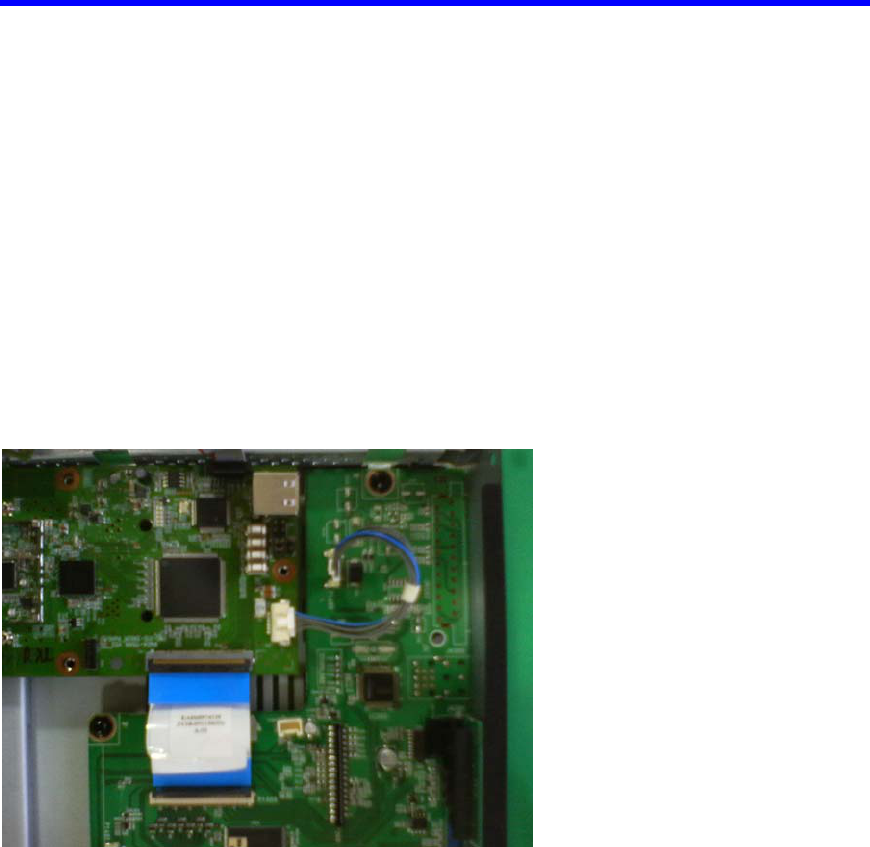
2.6 A/V and Control signal
J701 Connector
Figure 3: A/V and Control Cable connection Method
Page 7 of 15 Confidential
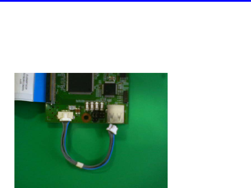
2.7 Power Supply
Input: 5V for TX
J702: Power connector
Figure 4: Power Cable connection Method

Page 8 of 15 Confidential
2.8 Reset Switch
The WMDA-119AN module is operating reset function.
SW501: Reset
Figure 5: Reset switch location
2.9 PC computer with a USB port
The PC should be installed with:
1. Java UART application
2. Scripts that activate Gemtek TX /Gemtek RX for a transmitting mode via UART
communication (supplied by Amimon).
Page 9 of 15 Confidential
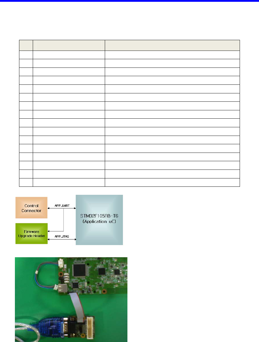
2.10 Firmware Update Header (J501)
# Signal Direction
1 VCC 3.3v, From Amimon
2 VCC 3.3v, From Amimon
3 GND Ground
4 APP_RST Reset
5 APP_TRST JTAG functionality to Microcontroller
6 GND Ground
7 TDI JTAG functionality to Microcontroller
8 APP_TXD Connect to Microcontroller
9 GND Ground
10 APP_RXD Connect to Microcontroller
11 APP_TMS JTAG functionality to Microcontroller
12 APP_RTCK
13 APP_TCK JTAG functionality to Microcontroller
14 APP_TDO JTAG functionality from Microcontroller
15 GND Ground
16 GND Ground
Figure 6: UART Cable connection Method
Page 10 of 15 Confidential
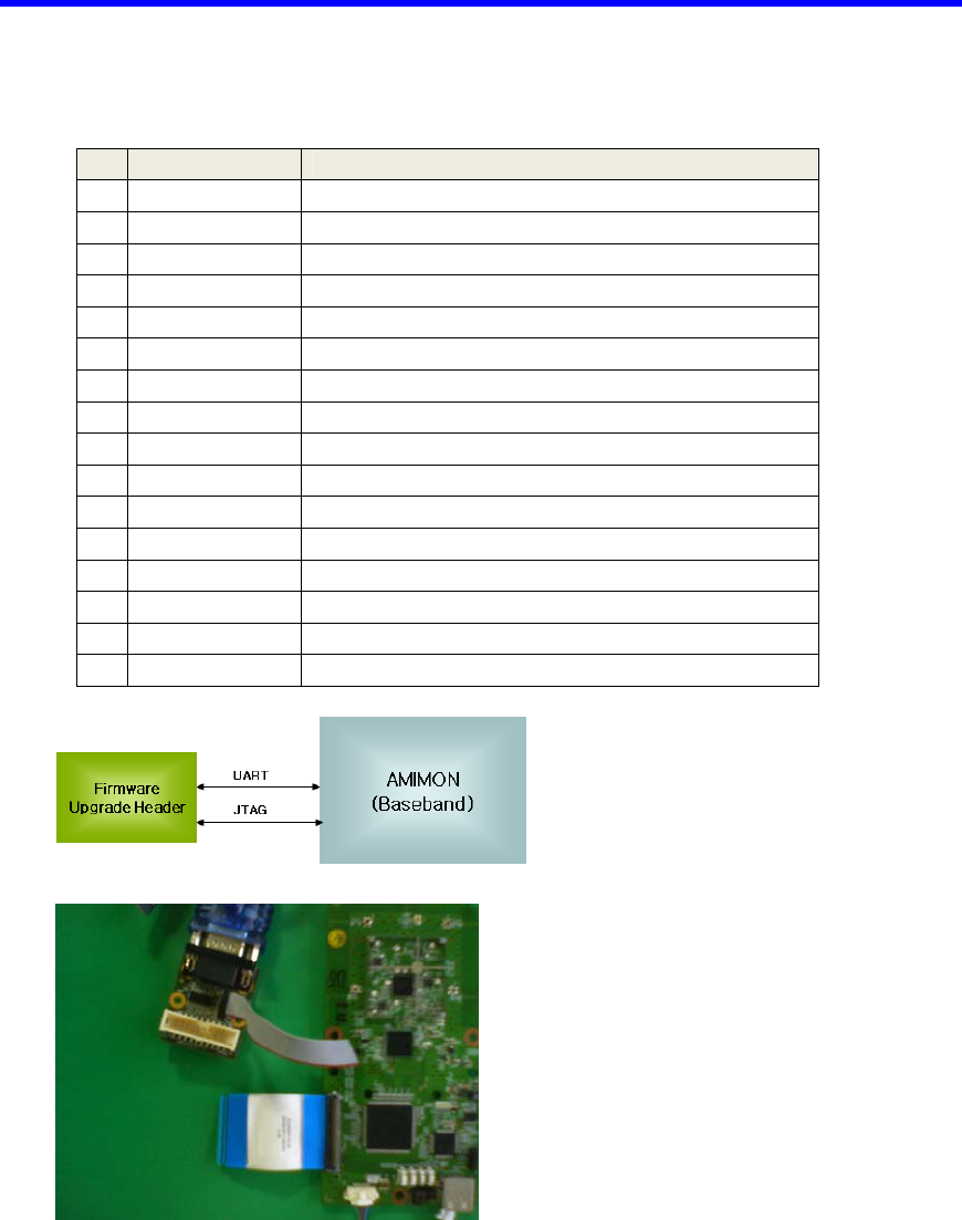
2.11 JTAG Debug Header (J2)
# Signal Direction
1 VCC 3.3v, From Amimon
2 VCC 3.3v, From Amimon
3 GND Ground
4 N.C.
5 TRST JTAG functionality to Amimon
6 GND Ground
7 TDI JTAG functionality to Amimon
8 UART_TX Connect to MAC uC (communications)
9 GND Ground
10 UART_RX Connect to MAC uC (communications)
11 TMS JTAG functionality to Amimon
12 N.C.
13 TCK JTAG functionality to Amimon
14 TDO JTAG functionality from Amimon
15 GND Ground
16 GND Ground
Figure 7: UART Cable connection Method
Page 11 of 15 Confidential
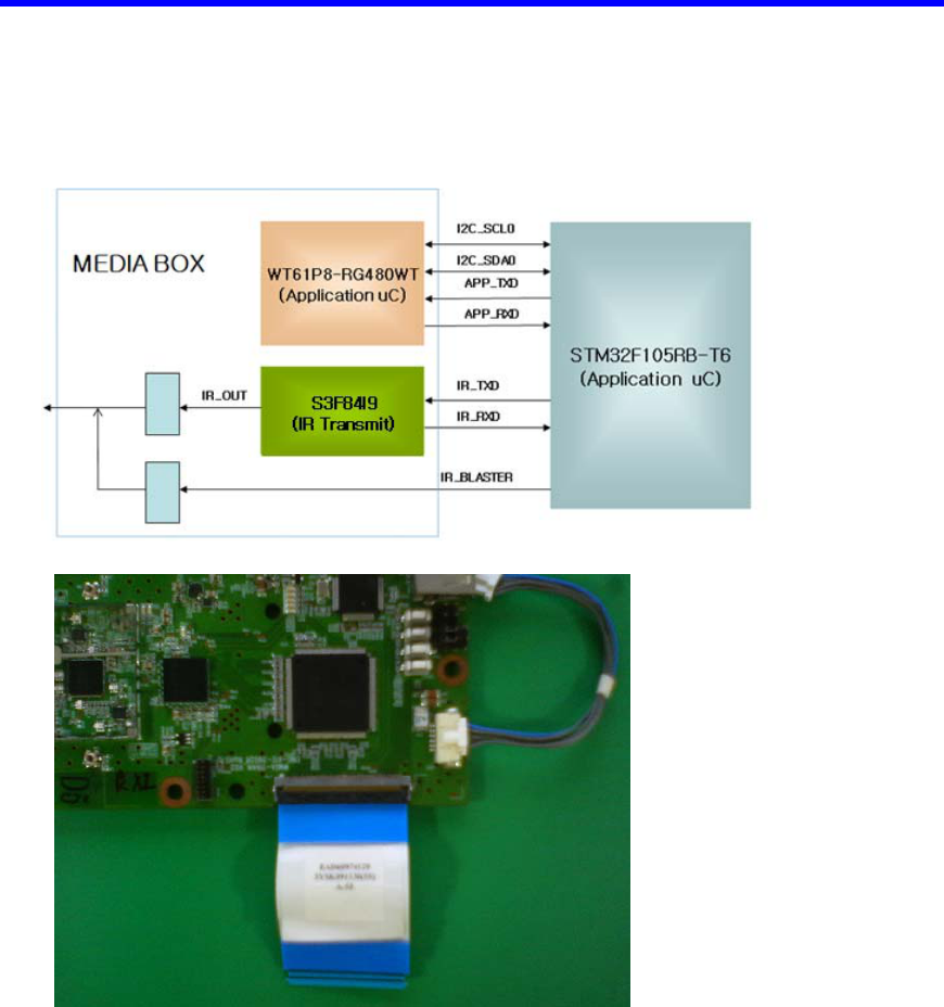
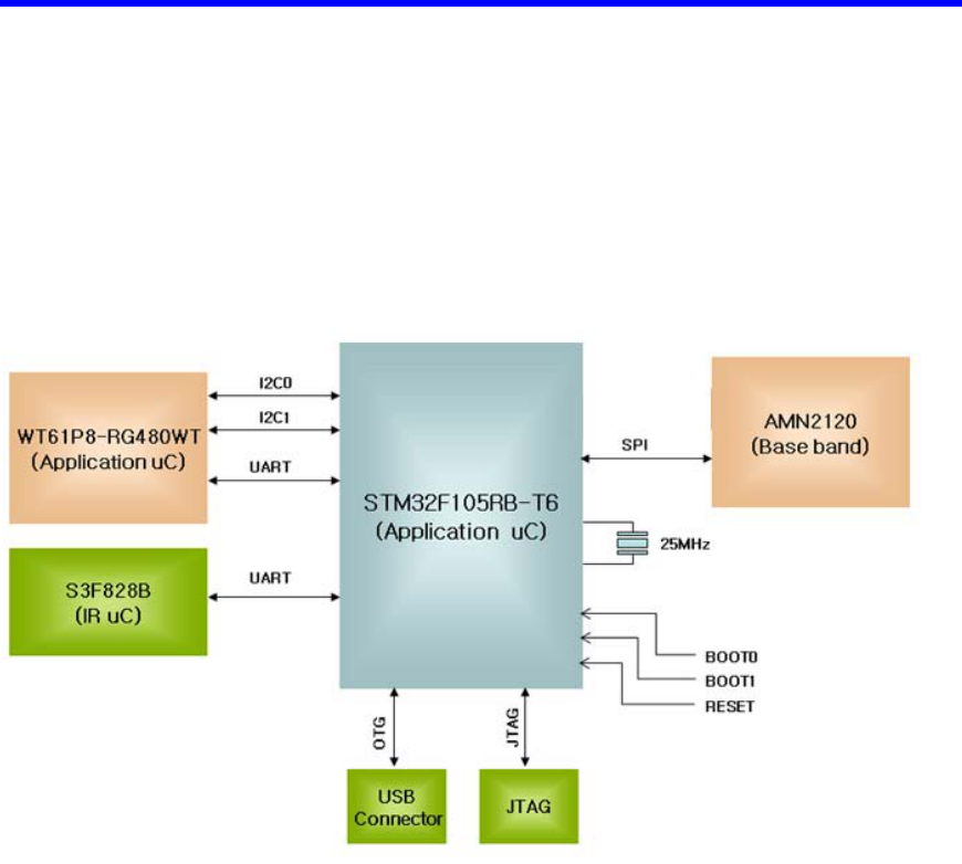
2.12 Application Microcontroller
The application micro-controller is used for communication channel from wireless
module to the Media box or TV, communication channel from wireless module to
Amimon base band chipset, communication channel from wireless module to IR Blaster
micro-controller, application debugging message send and receiver.
The I2C0 interface use to communicate between the media box and microcontroller. The
I2C1 interface is optional for factory mode. The purpose is registration between TX and
RX module.
Page 12 of 15 Confidential
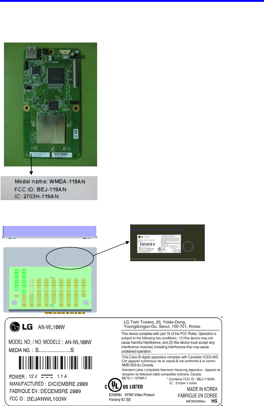
3 FCC Label
1) Label on the module
2) Label on the Media box
Media box bottom

Page 13 of 15 Confidential
4 FCC statement
Federal Communications Commission (FCC) Statement
You are cautioned that changes or modifications not expressly approved by the part
responsible for compliance could void the user’s authority to operate the equipment.
This equipment has been tested and found to comply with the limits for a Class B digital
device, pursuant to part 15 of the FCC rules. These limits are designed to provide
reasonable protection against harmful interference in a residential installation. This
equipment generates, uses and can radiate radio frequency energy and, if not installed and
used in accordance with the instructions, may cause harmful interference to radio
communications. However, there is no guarantee that interference will not occur in a
particular installation. If this equipment does cause harmful interference to radio or
television reception, which can be determined by turning the equipment off and on, the
user is encouraged to try to correct the interference by one or more of the following
measures:
-Reorient or relocate the receiving antenna.
-Increase the separation between the equipment and receiver.
-Connect the equipment into an outlet on a circuit different from that to which
the receiver is connected.
-Consult the dealer or an experienced radio/TV technician for help.
This device complies with Part 15 of the FCC Rules. Operation is subject to the following
two conditions:
1) this device may not cause harmful interference, and
2) this device must accept any interference received, including interference that may
cause undesired operation of the device of the device.
FCC Caution: for indoor use only, use outdoors or in other modes not covered by this
manual may violate the FCC regulation and violate the user authority to use the product.
Specially, within the 5.15-5.25 GHz band, U-NII device is restricted to indoor operations
to reduce any potential for harmful interference to co-channel MSS operations.
FCC RF Radiation Exposure Statement:
This equipment complies with FCC radiation exposure limits set forth for an uncontrolled
environment. This equipment should be installed and operated with minimum distance
20cm between the radiator & your body. End users must follow the specific operating

Page 14 of 15 Confidential
instructions for satisfying RF exposure compliance. This transmitter must not be co-
located or operating in conjunction with any other antenna or transmitter.