LG Electronics USA 26LDE 26" LCD TV MONITOR User Manual EMISSION TEST REPORT
LG Electronics USA 26" LCD TV MONITOR EMISSION TEST REPORT
UserManual.wiki
>
LG Electronics USA
>
26LDE User Manual
USERS MANUAL
Navigation menu
Upload a User Manual
Namespaces
Wiki Guide
HTML
PDF
Info
Views
User Manual
Discussion / Help
Navigation

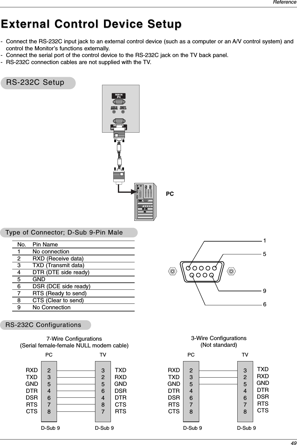
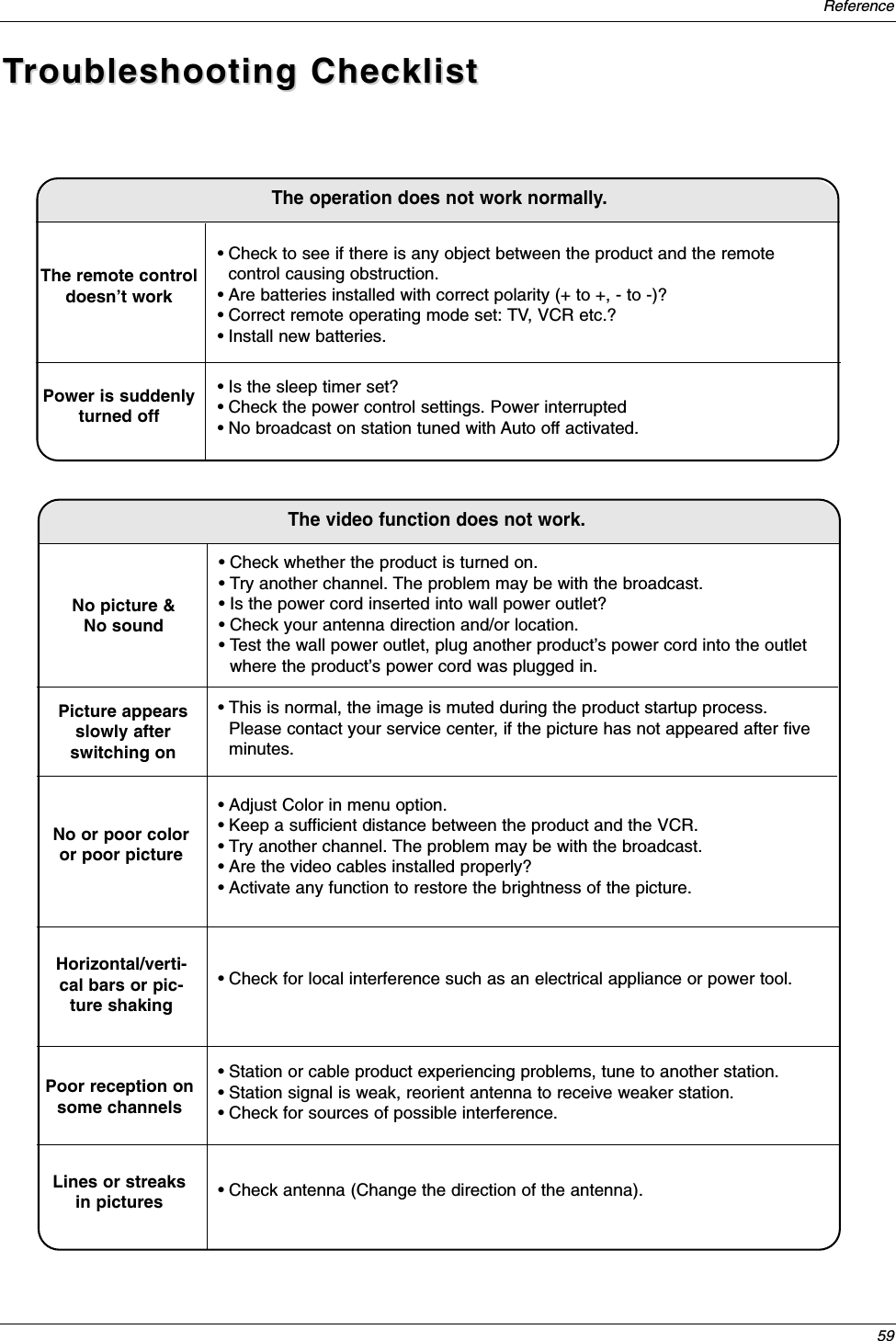
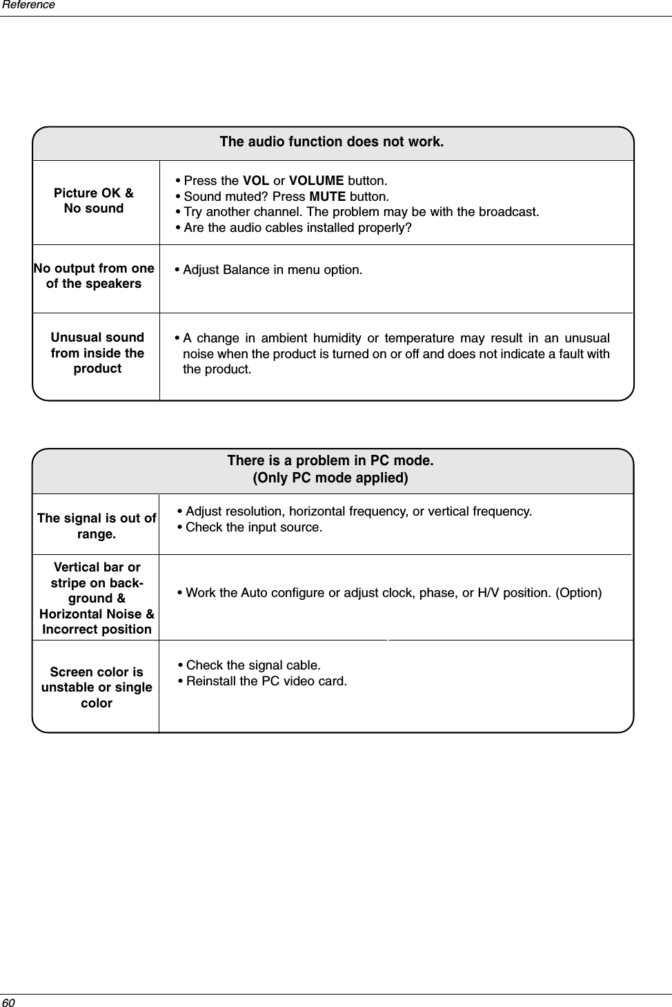
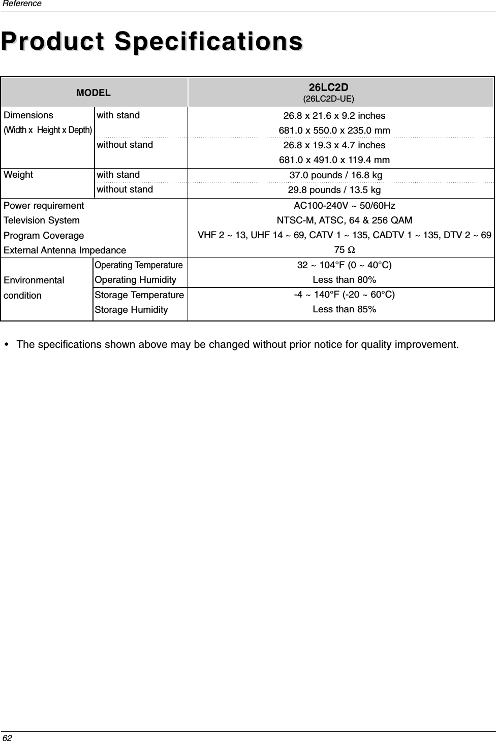
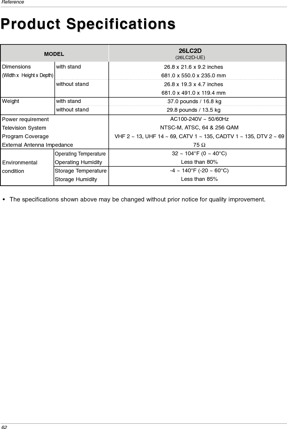
![50ReferenceSet IDSet ID- Use this function to specify a TV ID number. - Refer to ‘Real Data Mapping’. See page 51.• Baud rate : 9600 bps (UART)• Data length : 8 bits• Parity : None• Stop bit : 1 bit• Communication code : ASCII code* Use a crossed (reverse) cable.Communication ParametersCommunication Parameters1. Press the MENU button and then use D /Ebutton to select theSETUP menu.2. Press the Gbutton and then use D /Ebutton to select Set ID.3. Press the Gbutton and then use D /Ebutton to adjust Set ID tochoose the desired TV ID number. The adjustment range of Set IDis 1 ~ 99.4. Press EXIT button to return to TV viewing or press MENU button toreturn to the previous menu.Transmission*[Command 1]: First command to control the set.(j,k,m or x)*[Command 2]: Second command to control the set.*[Set ID]: You can adjust the set ID to choose desired monitorID number in Setup menu. Adjustment range is 1~ 99. When selecting Set ID ‘0’, every connectedthe TV is controlled. Set ID is indicated as decimal(1~99) on menu and as Hexa decimal (0x0~0x63)on transmission/receiving protocol.*[DATA]: To transmit command data.Transmit ‘FF’ data to read status of command.*[Cr]: Carriage ReturnASCII code ‘0x0D’*[ ]: ASCII code ‘space (0x20)’[Command1][Command2][ ][Set ID][ ][Data][Cr]TTransmission / Receiving Protocolransmission / Receiving ProtocolOK Acknowledgement* The Monitor transmits ACK (acknowledgement) based onthis format when receiving normal data. At this time, if thedata is data read mode, it indicates present status data. Ifthe data is data write mode, it returns the data of the PCcomputer.[Command2][ ][Set ID][ ][OK][Data][x]Error Acknowledgement* The Monitor transmits ACK (acknowledgement) based onthis format when receiving abnormal data from non-viablefunctions or communication errors.[Command2][ ][Set ID][ ][NG][Data][x]Data 1: Illegal Code2: Not supported function3: Wait more time18. Channel Tuning m a physical/program high major/program low major low minor high minor low attribute19. Channel Add/Del m b 00 ~ 0120. Key m c key code21. Input Select x b Gp.53COM-MAND 2COM-MAND 1DATA 0(Hexadecimal)DATA 1(Hexadecimal)DATA 2(Hexadecimal)DATA 3(Hexadecimal)DATA 4(Hexadecimal)DATA 5(Hexadecimal)01. Power k a 0 ~ 102. Input Select k b Gp.5103. Aspect Ratio k c Gp.5104. Screen Mute k d 0 ~ 105. Volume Mute k e 0 ~ 106. Volume Control k f 0 ~ 6407. Contrast k g 0 ~ 6408. Brightness k h 0 ~ 6409. Color k i 0 ~ 6410. Tint k j 0 ~ 6411. Sharpness k k 0 ~ 6412. OSD Select k l 0 ~ 113.Remote Control Lock Mode k m 0 ~ 114. Treble k r 0 ~ 6415. Bass k s 0 ~ 6416. Balance k t 0 ~ 6417. Color Temperature k u 0 ~ 3COMMAND 1 COMMAND 2 DATA(Hexadecimal)Command Reference ListCommand Reference ListEZ ScanManual ScanChannel EditDTV SignalInput SourceInput LabelSet ID G1](https://usermanual.wiki/LG-Electronics-USA/26LDE/User-Guide-685838-Page-27.png)