LG Electronics USA 32LDD 32" LCD TV MONITOR User Manual User s Manual H ok
LG Electronics USA 32" LCD TV MONITOR User s Manual H ok
USERS MANUAL

EUT Type: 32” LCD TV/ Monitor
FCC ID: BEJ32LDD
Test Report No.: GETEC-E3-05-080
FCC Class B Certification
APPENDIX H
: USER’S MANUAL
Please read this manual carefully before operating your set.
Retain it for future reference.
Record model number and serial number of the set.
See the label attached on the back cover and quote
this information to your dealer
when you require service.
P/NO : 3828TUL527A (0511-REV00)
Printed in Korea
OWNER’S MANUAL
LCD TV
MODELS: 32LC2D
37LC2D
42LC2D
PLASMA TV
MODELS: 42PC3D 42PC3D-UD
42PC3DV 42PC3DV-UD
50PC3D 50PC3D-UD
Internet Home Page : http://www.lge.com
http://www.lg.ca
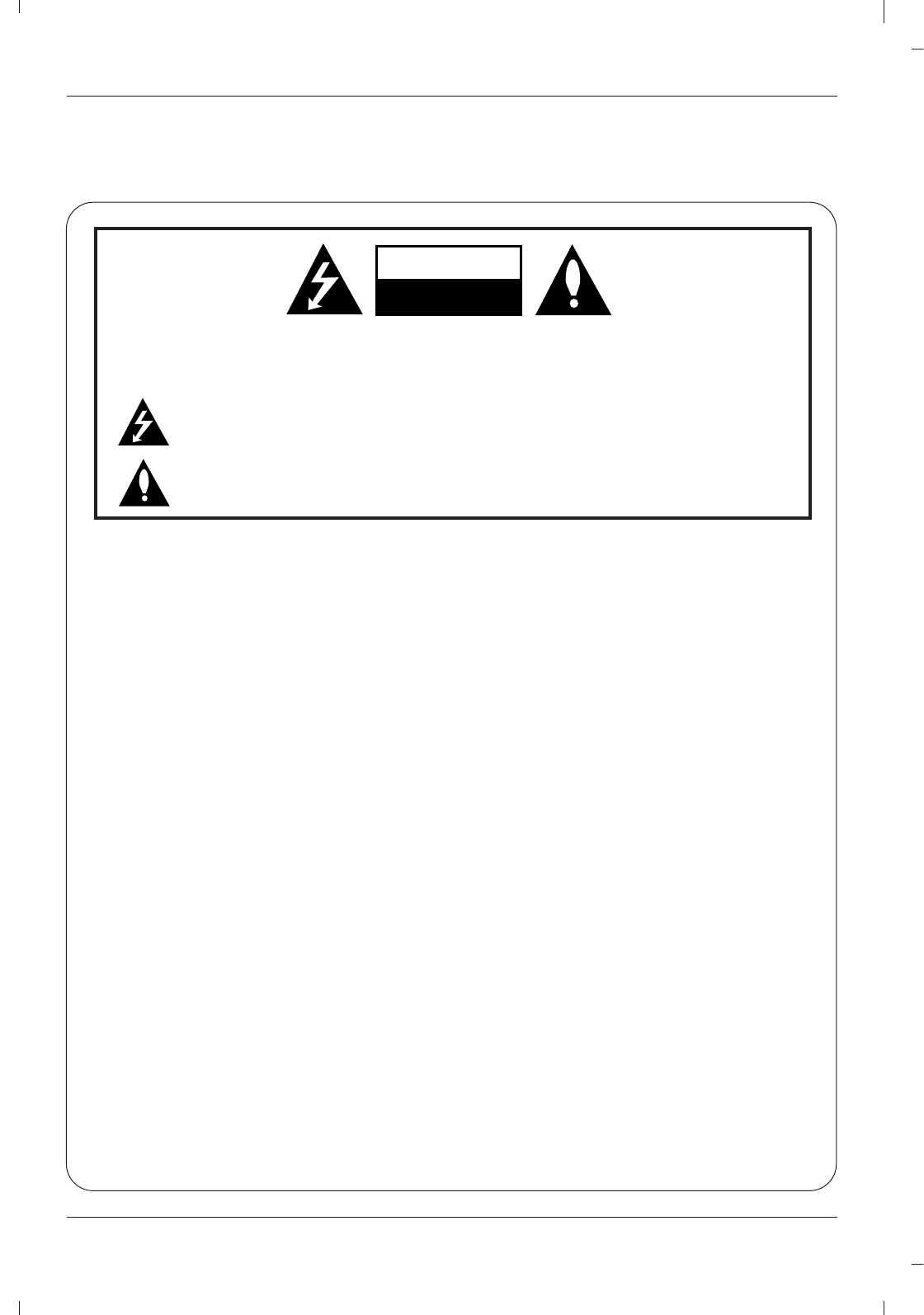
Warning
WARNING:
TO REDUCE THE RISK OF ELECTRIC SHOCK DO NOT REMOVE COVER (OR BACK). NO USER
SERVICEABLE PARTS INSIDE. REFER TO QUALIFIED SERVICE PERSONNEL.
The lightning flash with arrowhead symbol, within an equilateral triangle, is intended to alert the user to
the presence of uninsulated “dangerous voltage” within the product’s enclosure that may be of suffi-
cient magnitude to constitute a risk of electric shock to persons.
The exclamation point within an equilateral triangle is intended to alert the user to the presence of
important operating and maintenance (servicing) instructions in the literature accompanying the appli-
ance.
NOTE TO CABLE/TV INSTALLER:
This reminder is provided to call the CATV system installer’s attention to Article 820-40 of the National Electric
Code (U.S.A.). The code provides guidelines for proper grounding and, in particular, specifies that the cable
ground shall be connected to the grounding system of the building, as close to the point of the cable entry as prac-
tical.
REGULATORY INFORMATION
This equipment has been tested and found to comply with the limits for a Class B digital device, pursuant to Part
15 of the FCC Rules. These limits are designed to provide reasonable protection against harmful interference in
a residential installation. This equipment generates, uses and can radiate radio frequency energy and, if not
installed and used in accordance with the instructions, may cause harmful interference to radio communications.
However, there is no guarantee that interference will not occur in a particular installation. If this equipment does
cause harmful interference to radio or television reception, which can be determined by turning the equipment off
and on, the user is encouraged to try to correct the interference by one or more of the following measures:
- Reorient or relocate the receiving antenna.
- Increase the separation between the equipment and receiver.
- Connect the equipment into an outlet on a circuit different from that to which the receiver is connected.
- Consult the dealer or an experienced radio/TV technician for help.
Any changes or modifications not expressly approved by the party responsible for compliance could void the
user’s authority to operate the equipment.
CAUTION:
Do not attempt to modify this product in any way without written authorization from LG Electronics Corporation.
Unauthorized modification could void the user’s authority to operate this product.
U.S.A. only -----------------------------------------------
COMPLIANCE:
The responsible party for this product’s compliance is:
LG Electronics U.S.A., Inc.
1000 Sylvan Avenue, Englewood Cliffs, NJ 07632
Phone: 1-201-816-2000
http://www.lgusa.com
---------------------------------------------------------------
CAUTION
RISK OF ELECTRIC SHOCK
DO NOT OPEN
W
Warning
arning
Safety Instructions
WARNING :
To Reduce The Risk Of Fire Or Electric Shock, Do Not Expose This Apparatus To Rain Or Moisture.
Apparatus shall not be exposed to dripping or splashing and no objects filled with liquids, such as vases, shall be placed on the
apparatus.
IMPORTANT SAFETY INSTRUCTIONS
1. Read these instructions.
2. Keep these instructions.
3. Heed all warnings.
4. Follow all instructions.
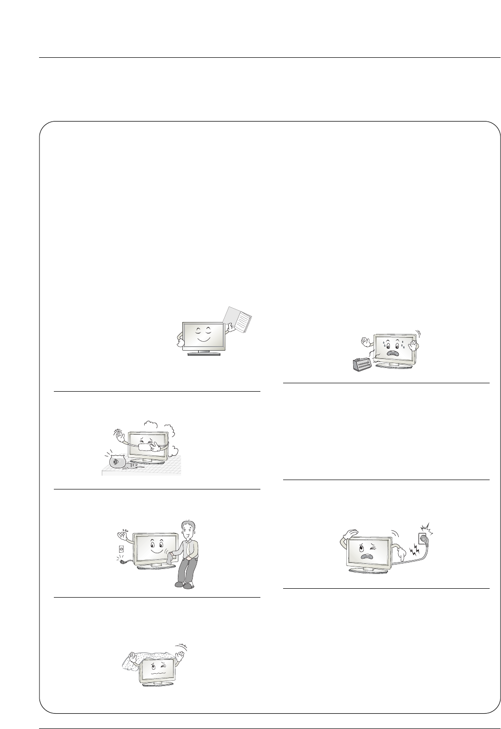
5. Do not use this apparatus near water.
6. Clean only with a dry cloth.
7. Do not block any of the ventilation openings. Install in
accordance with the manufacturer’s instructions.
8. Do not install near any heat sources such as radiators,
heat registers, stoves, or other apparatus (including
amplifiers) that produce heat.
9. Do not defeat the safety purpose of the polarized or
grounding type plug. A polarized plug has two blades
with one wider than the other. A grounding type plug has
two blades and a third grounding prong. The wide blade
or the third prong is provided for your safety. When the
provided plug does not fit into your outlet, consult an
electrician for replacement of the obsolete outlet.
10. Protect the power cord from being walked on or
pinched particularly at plugs, convenience recepta-
cles, and the point where they exit from the apparatus.
11. Only use the attachments / accessories specified by
the manufacturer.
Safety Instructions
Safety Instructions
Owner's Manual
Safety Instructions
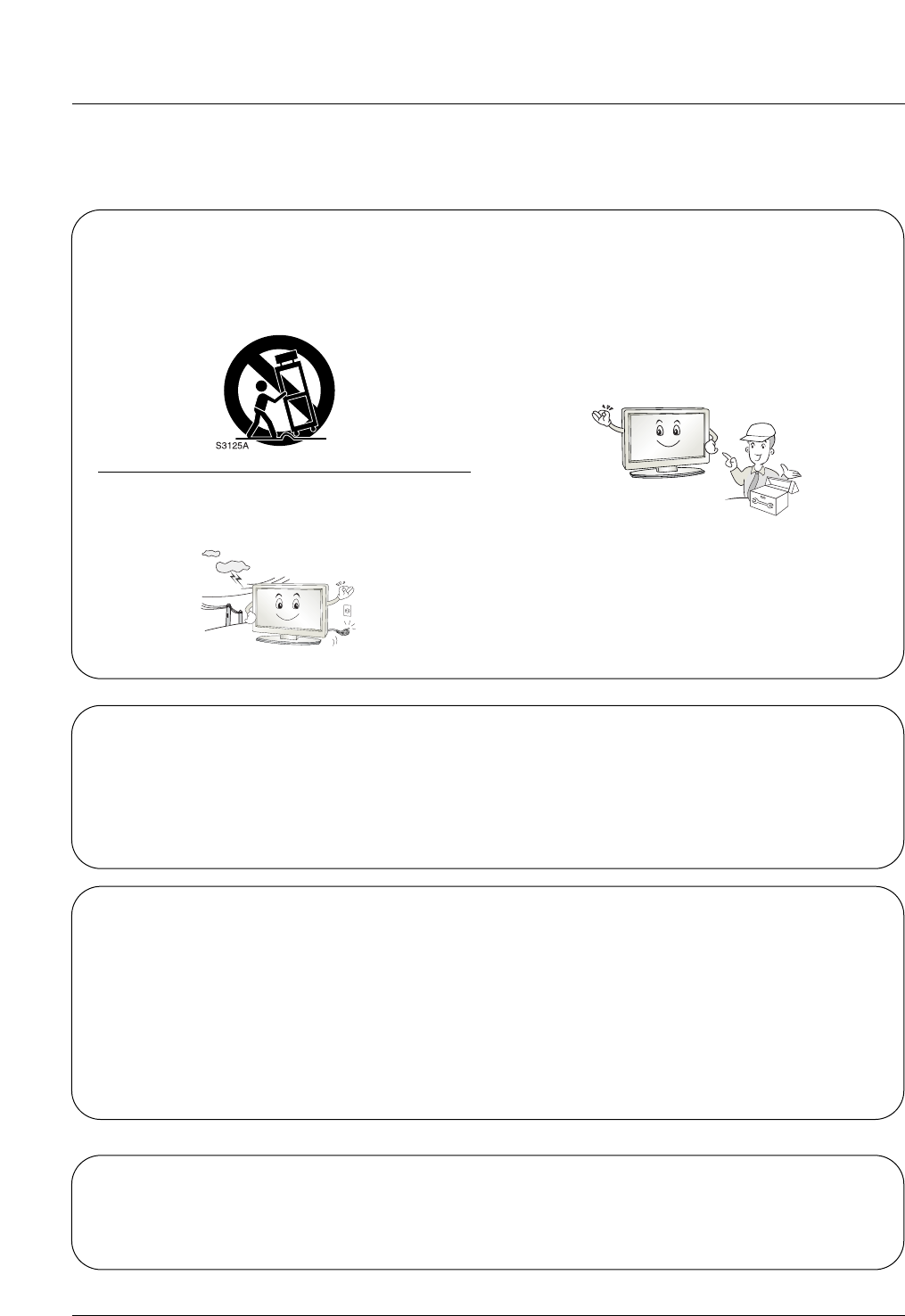
12. Use only with a cart, stand, tripod, bracket, or table
specified by the manufacturer, or sold with the appa-
ratus. When a cart is used, use caution when moving
the cart / apparatus combination to avoid injury from
tip-over.
13. Unplug this apparatus during lightning storms or when
unused for long periods of time.
14. Refer all servicing to qualified service personnel.
Servicing is required when the apparatus has been
damaged in any way, such as power supply cord or
plug is damaged, liquid has been spilled or objects
have fallen into the apparatus, the apparatus has been
exposed to rain or moisture, does not operate normal-
ly, or has been dropped.
On Disposal
a. The fluorescent lamp used in this product contains a small amount of mercury.
b. Do not dispose of this product with general household waste.
Disposal of this product must be carried out in accordance to the regulations of your local authority.
Note
- If the TV feels cold to the touch, there may be a small “flicker” when when it is turned on. This is normal, there is noth-
ing wrong with TV.
- Some minute dot defects may be visible on the screen, appearing as tiny red, green, or blue spots. However, they have
no adverse effect on the monitor's performance.
- Avoid touching the LCD screen or holding your finger(s) against it for long periods of time. Doing so may produce some
temporary distortion effects on the screen.
CAUTION concerning the Power Cord
Most appliances recommend they be placed upon a dedicated circuit; that is, a single outlet circuit which powers only that
appliance and has no additional outlets or branch circuits. Check the specification page of this owner's manual to be certain.
Do not overload wall outlets. Overloaded wall outlets, loose or damaged wall outlets, extension cords, frayed power cords,
or damaged or cracked wire insulation are dangerous. Any of these conditions could result in electric shock or fire.
Periodically examine the cord of your appliance, and if its appearance indicates damage or deterioration, unplug it, discon-
tinue use of the appliance, and have the cord replaced with an exact replacement part by an authorized servicer.
Protect the power cord from physical or mechanical abuse, such as being twisted, kinked, pinched, closed in a door, or
walked upon. Pay particular attention to plugs, wall outlets, and the point where the cord exits the appliance.
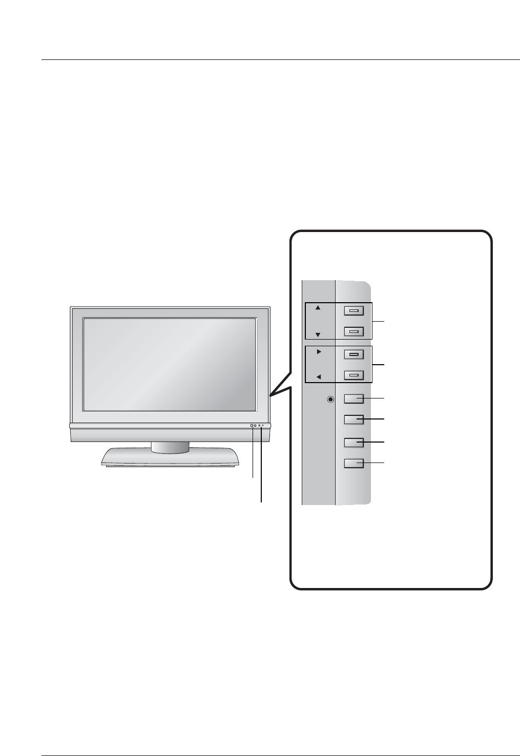
Introduction
Controls
Controls (Model Name: 32/37/42LC2D)
(Model Name: 32/37/42LC2D)
- This is a simplified representation of front panel.
- Here shown may be somewhat different from your TV.
R
CH
VOL
VOL
ENTER
ENTER
MENU
MENU
INPUT
INPUT
ON/OFF
ON/OFF
CHANNEL Buttons
VOLUME Buttons
ENTER Button
MENU Button
INPUT Button
ON/OFF Button
Remote Control Sensor
Power/Standby Indicator
• illuminates red in standby mode.
• illuminates green when the set is
switched on.
Introduction
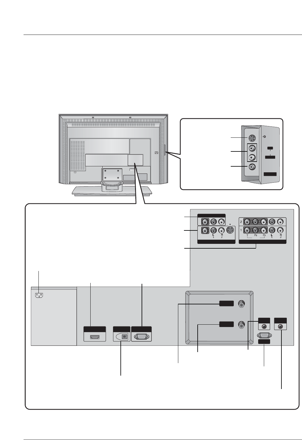
Connection Options (Model Name: 32/37/42LC2D)
Connection Options (Model Name: 32/37/42LC2D)
AC IN
AV IN 2
AV IN 2
L/
L/
MONO
MONO
R
AUDIO
AUDIO
S-VIDEO
S-VIDEO
VIDEO
VIDEO
HDMI/DVI IN
HDMI/DVI IN
DIGITAL AUDIO OUT
DIGITAL AUDIO OUT
OPTICAL
OPTICAL
RS-232C IN
RS-232C IN
(CONTROL
(CONTROL
&SERVICE)
SERVICE)
REMOTE
CONTROL
RGB IN
RGB IN
(PC
(PC
/
DTV)
DTV)
AUDIO IN
AUDIO IN
(RGB/DVI)
(RGB/DVI)
VIDEO
VIDEO
AUDIO
AUDIO
MONO
( )
VIDEO
VIDEO
AUDIO
COMPONENT IN
COMPONENT IN
S-VIDEO
S-VIDEO
AV IN 1
AV IN 1
AV OUT
AV OUT
ANTENNA
ANTENNA
IN
CABLE
CABLE
IN
AC IN
AUDIO Input
S-VIDEO Input
VIDEO Input
DIGITAL AUDIO OUT
OPTICAL
AV OUT
AV IN1
COMPONENT IN 1/2
HDMI / DVI IN
ANTENNA IN
CABLE IN AUDIO IN
(RGB/DVI)
RGB IN
(PC/DTV)
AC IN
RS-232C INPUT
(CONTROL&SERVICE)
REMOTE CONTROL Port
- Here shown may be somewhat different from your TV.
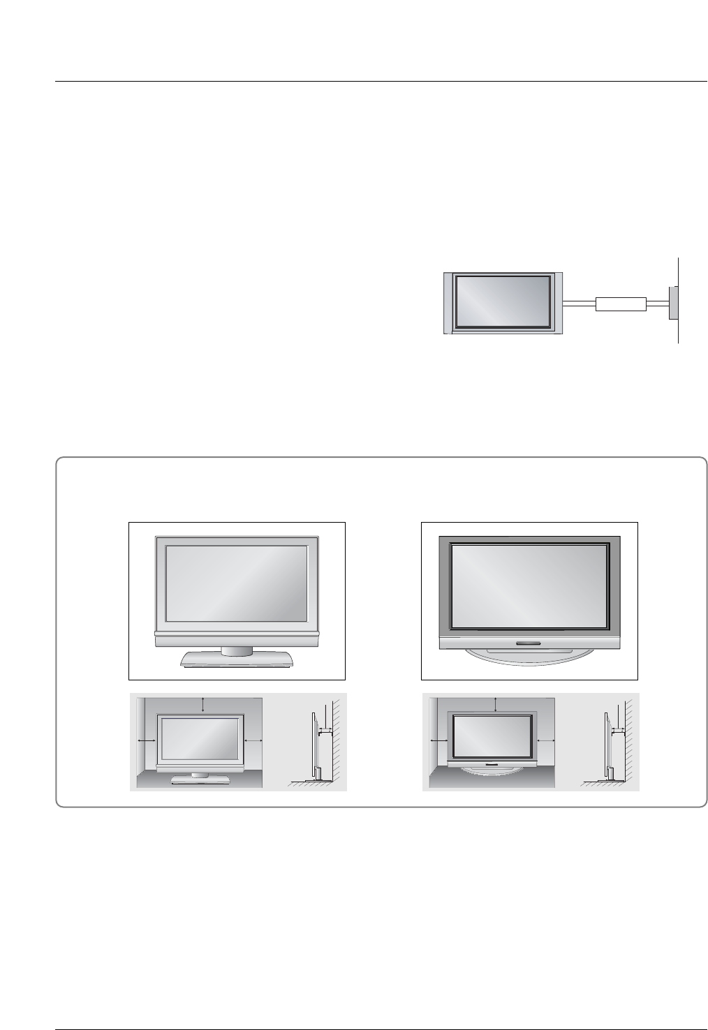
Installation
Installation
Installation
Desktop Pedestal Installation
4 inches
4 inches4 inches
4 inches 4 inches
4 inches4 inches
4 inches
For proper ventilation, allow a clearance of 4" on each side and from the wall.
GROUNDING
Ensure that you connect the earth ground wire to prevent pos-
sible electric shock. If grounding methods are not possible,
have a qualified electrician install a separate circuit breaker.
Do not try to ground the unit by connecting it to telephone
wires, lightening rods, or gas pipes.
Power
Supply
Short-circuit
Breaker
• The TV can be installed in various ways such as on a wall, or on a desktop etc.
• The TV is designed to be mounted horizontally.
Installation
How to join the product assembly to the wall to protect the set tumbling
- Set it up close to the wall so the product doesn’t fall over when it is pushed backwards.
- The instructions shown below is a safer way to set up the product, which is to fix it on the wall so the prod-
uct doesn’t fall over when it is pulled in the forward direction. It will prevent the product from falling for-
ward and hurting people. It will also prevent the product from damage caused by fall. Please make sure
that children don’t climb on or hang from the product.
42PC3D/42PC3DV/50PC3D
Notes
• When moving the product to another place undo the ropes first.
• Use a product holder or a cabinet that is big and strong enough for the size and weight of the product.
• To use the product safely make sure that the height of the bracket that is mounted on the wall is same
as that of the product.
2
1
3
Use the bracket and the bolt to fix the product to the wall as shown in the picture.
Secure the bracket with the bolt (not provided as parts of the product, must purchase separately) on
the wall.
Use a sturdy rope (not provided as parts of the product, must purchase separately) to tie the product.
It is safer to tie the rope so it becomes horizontal between the wall and the product.
1
2
3
32/37/42LC2D
If the set will be mounted on a desk top, insert the 2 eye-bolts and tighten them securely in the upper
holes as shown.
Install the wall brackets on the wall with 2 bolts*, (not supplied with the product), as shown.
Match the height of the eye-bolts and the wall brackets.
Check to be sure the eye-bolts and the brackets are tightened securely.
Secure the TV assembly to the wall with strong strings or wire cables, (not supplied with the product), as
shown.
1
2
3
4
5
Installation
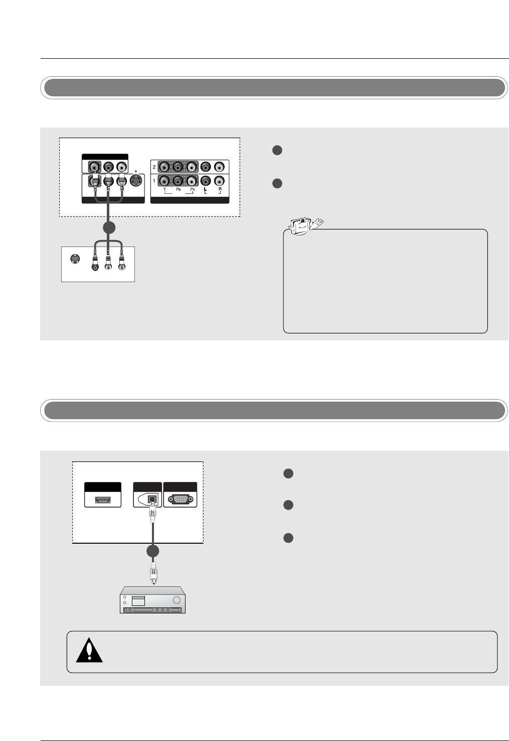
Digital Audio Output
1
2
3
Connect one end of an optical cable to the TV
Digital Audio Optical Output port.
Connect the other end of the optical cable to the
digital audio optical input on the audio equipment.
See the external audio equipment instruction
manual for operation.
When connecting with external audio equip-
ments, such as amplifiers or speakers, please
turn the TV speakers off.
HDMI/DVI IN
DIGITAL AUDIO OUT
OPTICAL
RS-232C INRS-232C IN
(CONTROL&SERVICE)
- Send the TV’s audio to external audio equipment (stereo system) via the Digital Audio Output Optical port.
CAUTION
Do not look into the optical output port. Looking at the laser beam may damage your vision.
1/2
Monitor Out Setup
1
2
Connect the second TV or monitor to the TV’s AV
OUTPUT jacks.
See the Operating Manual of the second TV or
monitor for further details regarding that device’s
input settings.
S-VIDEO IN
(R) AUDIO (L)
VIDEO
VIDEOVIDEO
AUDIO
MONO
( )
VIDEOVIDEO
AUDIOUDIO
COMPONENT IN
S-VIDEO
AV IN 1
AV OUT
- The TV has a special signal output capability which allows you to hook up a second TV or monitor.
1/2
• Component 1-2, RGB-PC/RGB-DTV,
HDMI/DVI, DTV input sources cannot be used
for Monitor out.
• When connecting with external audio equip-
ments, such as amplifiers or speakers, please
turn the TV speakers off. (Refer to p.43)
• We recommend to use the video and audio
output jacks for VCR recording.
Installation
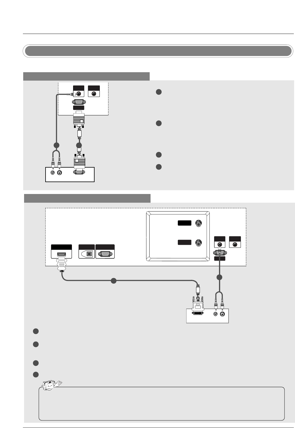
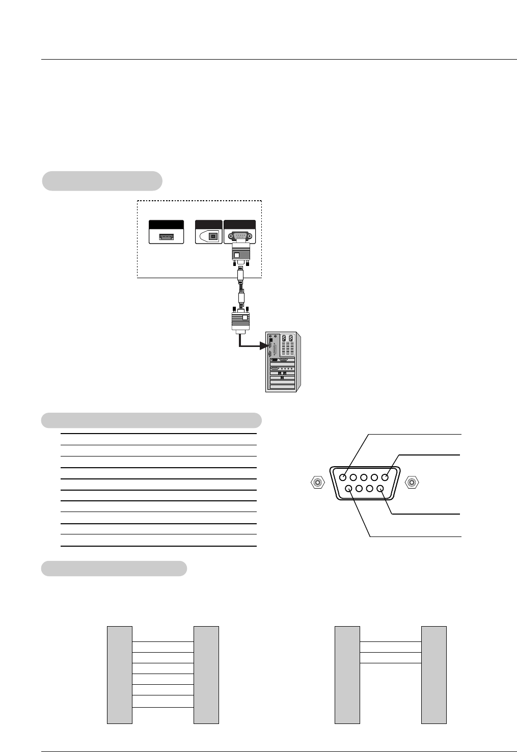
- This TV provides Plug and Play capability, meaning that the PC adjusts automatically to the TV's settings.
PC Setup
When connecting with a D-sub 15 pin cable
1
2
3
4
Connect the RGB output of the PC to the RGB IN
(PC/DTV) (32/37/42LC2D Model) / RGB
(PC/DTV) (42PC3D/3DV/50PC3D Model) jack on
the set.
Connect the PC audio outputs to the AUDIO IN
(RGB/DVI) (32/37/42LC2D Model) /AUDIO
(RGB/DVI) (42PC3D/3DV/50PC3D Model) jack on
the set.
Turn on the PC and the set.
Select RGB-PC input source with using the
TV/VIDEO button on the remote control.
(R) AUDIO (L)
RGB-PC OUTPUT
REMOTE
CONTROL
RGB IN
(PC/DTV)
AUDIO INAUDIO IN
(RGB/DVI)
1
2
PC
When connecting with a HDMI to DVI cable
1
2
3
4
Connect the DVI output of the PC to the HDMI/DVI IN jack on the set.
Connect the audio outputs of the PC to the AUDIO IN (RGB/DVI) (32/37/42LC2D Model)
/AUDIO (RGB/DVI) (42PC3D/3DV/50PC3D Model) jack on the set.
Turn on the PC and the set.
Select HDMI/DVI input source with using the TV/VIDEO button on the remote control.
(R) AUDIO (L)
DVI-PC OUTPUT
HDMI/DVI IN
DIGITAL AUDIO OUT
OPTICAL
RS-232C INRS-232C IN
(CONTROL&SERVICE)
REMOTE
CONTROL
RGB IN
(PC/DTV)
AUDIO INAUDIO IN
(RGB/DVI)
ANTENNA
IN
CABLE
IN
PC
• If the PC has a DVI output and no HDMI output, a separated audio connection is necessary.
• If the PC does not support Auto DVI, you need to set the output resolution appropriately. To get the
best picture quality, adjust the output resolution of PC graphics card's output resolution to
1024x768, 60Hz.
12
30
Installation
1. To get the best picture quality, adjust the PC
graphics card to 1024x768, 60Hz.
2. Depending on the graphics card, DOS mode may
not work if a HDMI to DVI Cable is in use.
3. When Source Devices connected with HDMI1/DVI
Input, output PC Resolution (VGA, SVGA, XGA),
Position and Size may not fit to Screen.Press the
ADJUST button to adjust the screen Position of TV
SET and contact an PC graphics card service cen-
ter.
4. When Source Devices connected with HDMI/DVI
Input, output TV SET Resolution (480p, 720p,
1080i) and TV SET Display fit EIA/CEA-861-B
Specification to Screen. If not, refer to the Manual
of HDMI/DVI Source Devices or contact your ser-
vice center.
5. In case HDMI/DVI Source Devices is not connect-
ed Cable or poor cable connection, "NO SIGNAL"
OSD display in HDMI1/DVI Input. In case that
Video Resolution is not supported TV SET output
in HDMI/DVI Source Devices, "INVALID FORMAT"
OSD display. Refer to the Manual of HDMI1/DVI
Source Devices or contact your service center.
6. Check the image on your TV. There may be noise
associated with the resolution, vertical pattern,
contrast or brightness in PC, HDMI/DVI mode. If
noise is present, change the PC or HDMI/DVI
mode to another resolution, change the refresh
rate to another rate or adjust the brightness and
contrast on the menu until the picture is clear. If the
refresh rate of the PC graphic card can not be
changed, change the PC graphic card or consult
the manufacturer of the PC graphic card.
7. Avoid keeping a fixed image on the TV's screen for
a long period of time. The fixed image may become
permanently imprinted on the screen.
8. The synchronization input form for Horizontal and
Vertical frequencies is separate.
Supported Display Resolution
(RGB-PC, HDMI/DVI Mode)
Resolution
*640x350
*720x400
640x480
Horizontal
Frequency (kHz)
31.468
31.469
31.469
37.861
37.500
70.09
70.08
59.94
72.80
75.00
Vertical
Frequency (Hz)
Resolution
* RGB-PC only
800x600
1024x768
Horizontal
Frequency (kHz)
35.156
37.879
48.077
46.875
48.363
56.476
60.023
56.25
60.31
72.18
75.00
60.00
70.06
75.02
Vertical
Frequency (Hz)
Installation
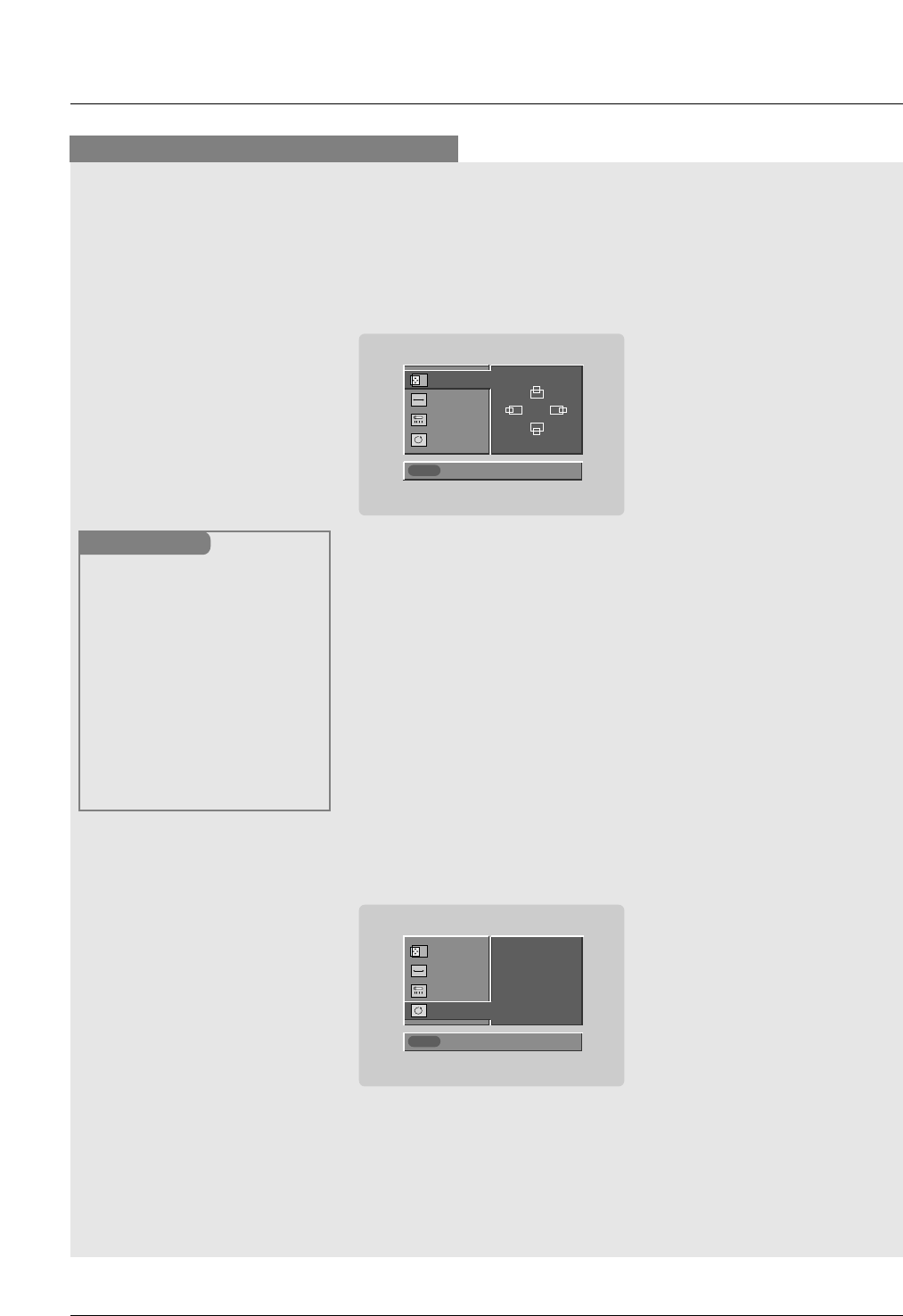
* Adjustment for screen Position, Size, and Phase
* Initializing (Reset to original factory values)
- To initialize the adjusted values
Close
POSITION G
SIZE
PHASE
RESET
Adjust
D
FG
E
Close
POSITION
SIZE
PHASE
RESET G
Adjust
Initialize Settings
Position This function is to adjust
picture to left/right and
up/down as you prefer.
Size This function is to mini-
mize any vertical bars or
stripes visible on the
screen background. And
the horizontal screen size
will also change.
Phase This function allows you to
remove any horizontal
noise and clear or sharpen
the image of characters.
Mini Glossary
- When RGB connect to PC input and select the RGB-PC, this function is used.
- When HDMI/DVI connect to PC input and select HDMI/DVI input, this function is used.
- In RGB-DTV mode, SIZE and PHASE is not available.
- After connecting RGB-PC or HDMI/DVI to PC input and checking the screen quality.
Press the ADJUST button and then use D /Ebutton to select POSITION,
SIZE, or PHASE.
Press ENTER button and then use D /E/F /G buttons to make
appropriate adjustments.
• The PHASE adjustment range is -16 ~ +16.
(In HDMI/DVI-PC mode, PHASE is not available.)
• The SIZE adjustment range is -50 ~ +50.
Press ENTER button.
1
2
3
Press the ADJUST button and then use D /Ebutton to select the
RESET option.
Press ENTER button and then use F /G button to select Yes.
Press ENTER button.
1
2
3
Screen Setup for PC mode
Reference
No. Pin Name
1 No connection
2 RXD (Receive data)
3 TXD (Transmit data)
4 DTR (DTE side ready)
5 GND
6 DSR (DCE side ready)
7 RTS (Ready to send)
8 CTS (Clear to send)
9 No Connection
1
5
6
9
2
3
5
4
6
7
8
RXD
TXD
GND
DTR
DSR
RTS
CTS
TXD
RXD
GND
DSR
DTR
CTS
RTS
PC
7-Wire Configurations
(Serial female-female NULL modem cable)
D-Sub 9
3
2
5
6
4
8
7
TV
D-Sub 9
2
3
5
4
6
7
8
RXD
TXD
GND
DTR
DSR
RTS
CTS
TXD
RXD
GND
DTR
DSR
RTS
CTS
PC
3-Wire Configurations
(Not standard)
D-Sub 9
3
2
5
4
6
7
8
TV
D-Sub 9
- Connect the RS-232C input jack to an external control device (such as a computer or an A/V control system) and
control the Monitor’s functions externally.
- Connect the serial port of the control device to the RS-232C jack on the TV back panel.
- RS-232C connection cables are not supplied with the TV.
T
Type of Connector; D-Sub 9-Pin Male
ype of Connector; D-Sub 9-Pin Male
RS-232C Configurations
RS-232C Configurations
External Control Device Setup
External Control Device Setup
RS-232C Setup
RS-232C Setup
HDMI/DVI IN
DIGITAL AUDIO OUT
OPTICAL
RS-232C IN
(CONTROL&SERVICE)
PC
Reference
Set ID
Set ID
- Use this function to specify a TV ID number.
- Refer to ‘Real Data Mapping’. See page 56.
• Baud rate : 9600 bps (UART)
• Data length : 8 bits
• Parity : None
• Stop bit : 1 bit
• Communication code : ASCII code
* Use a crossed (reverse) cable.
Communication Parameters
Communication Parameters
1. Press the MENU button and then use D /Ebutton to select the
SETUP menu.
2. Press the Gbutton and then use D /Ebutton to select Set ID.
3. Press the Gbutton and then use D /Ebutton to adjust Set ID to
choose the desired TV ID number. The adjustment range of Set ID
is 1 ~ 99.
4. Press EXIT button to return to TV viewing or press MENU button to
return to the previous menu.
Previous
MENU
EZ Scan
Manual Scan
Channel Edit
DTV Signal
Input Source
Input Label
Set ID G1
SETUP G
VIDEO
AUDIO
TIME
OPTION
LOCK
Transmission
*[Command 1]: First command to control the set.(j,k,m or x)
*[Command 2]: Second command to control the set.
*[Set ID]: You can adjust the set ID to choose desired monitor
ID number in Setup menu. Adjustment range is 1
~ 99. When selecting Set ID ‘0’, every connected
the TV is controlled. Set ID is indicated as decimal
(1~99) on menu and as Hexa decimal (0x0~0x63)
on transmission/receiving protocol.
*[DATA]: To transmit command data.
Transmit ‘FF’ data to read status of command.
*[Cr]: Carriage Return
ASCII code ‘0x0D’
*[ ]: ASCII code ‘space (0x20)’
[Command1][Command2][ ][Set ID][ ][Data][Cr]
T
Transmission / Receiving Protocol
ransmission / Receiving Protocol
OK Acknowledgement
* The Monitor transmits ACK (acknowledgement) based on
this format when receiving normal data. At this time, if the
data is data read mode, it indicates present status data. If
the data is data write mode, it returns the data of the PC
computer.
[Command2][ ][Set ID][ ][OK][Data][x]
Error Acknowledgement
* The Monitor transmits ACK (acknowledgement) based on
this format when receiving abnormal data from non-viable
functions or communication errors.
[Command2][ ][Set ID][ ][NG][Data][x]
Data 1: Illegal Code
2: Not supported function
3: Wait more time
22. Channel Tuning m a physical/program high major/program low major low minor high minor low attribute
23. Channel Add/Del m b 00 ~ 01
24. Key m c key code
25. Input Select x b *(Refer to p.59)
COM-
MAND 2
COM-
MAND 1
DATA 0
(Hexadecimal)
DATA 1
(Hexadecimal)
DATA 2
(Hexadecimal)
DATA 3
(Hexadecimal)
DATA 4
(Hexadecimal)
DATA 5
(Hexadecimal)
01. Power k a 0 ~ 1
02. Input Select k b 0 ~ 8
03. Aspect Ratio k c *(Refer to p.56)
04. Screen Mute k d 0 ~ 1
05. Volume Mute k e 0 ~ 1
06. Volume Control k f 0 ~ 64
07. Contrast k g 0 ~ 64
08. Brightness k h 0 ~ 64
09. Color k i 0 ~ 64
10. Tint k j 0 ~ 64
11. Sharpness k k 0 ~ 64
12. OSD Select k l 0 ~ 1
13.
Remote Control Lock Mode
k m 0 ~ 1
14. Treble k r 0 ~ 64
15. Bass k s 0 ~ 64
16. Balance k t 0 ~ 64
17. Color Temperature k u 0 ~ 2
18. ISM Method j p *(Refer to p.58)
19. Low Power j q 0 ~ 1
20. Orbiter Time Setting j r 1 ~ FE
21. Orbiter Pixel Setting j s 1 ~3
COMMAND 1 COMMAND 2 DATA
(Hexadecimal)
Command Reference List
Command Reference List
* Command 18~21: 42PC3D/3DV, 50PC3D models only
Reference
1. Here’s a great way to keep the dust off your screen for a while. Wet a soft cloth in a mixture of lukewarm water
and a little fabric softener or dish washing detergent. Wring the cloth until it’s almost dry, and then use it to wipe
the screen.
2. Make sure the excess water is off the screen, and then let it air-dry before you turn on your TV.
To remove dirt or dust, wipe the cabinet with a soft, dry, lint-free cloth.
Please be sure not to use a wet cloth.
If you expect to leave your TV dormant for a long time (such as a vacation), it’s a good idea to
unplug the power cord to protect against possible damage from lightning or power surges.
- Early malfunctions can be prevented. Careful and regular cleaning can extend the amount of time you will have
your new TV. Be sure to turn the power off and unplug the power cord before you begin any cleaning.
Cleaning the Screen
Cleaning the Screen
Cleaning the Cabinet
Cleaning the Cabinet
Extended
Extended Absence
Absence
Maintenance
Maintenance
Product Specifications
Product Specifications
• The specifications shown above may be changed without prior notice for quality improvement.
MODEL
Power requirement
Television System
Program Coverage
External Antenna Impedance
Operating Temperature Range
Operating Humidity Range
32LC2D 37LC2D 42LC2D
NTSC-M, ATSC, 64 & 256 QAM
VHF 2 ~ 13, UHF 14 ~ 69, CATV 1 ~ 135, CADTV 1 ~ 135, DTV 2 ~ 69
75 Ω
32 ~ 104°F (0 ~ 40°C)
Less than 80%
AC100-240V ~ 50/60Hz 1.5A AC100-240V ~ 50/60Hz 2.0A AC100-240V ~ 50/60Hz 2.5A
MODEL
Power requirement
Television System
Program Coverage
External Antenna Impedance
Operating Temperature Range
Operating Humidity Range
Resolution
42PC3D/3DV-UD 50PC3D-UD
AC100-240V ~ 50/60Hz 2.0A
NTSC-M, ATSC, 64 & 256 QAM
VHF 2 ~ 13, UHF 14 ~ 69, CATV 1 ~ 135, CADTV 1 ~ 135, DTV 2 ~ 69
75 Ω
32 ~ 104°F (0 ~ 40°C)
Less than 80%
852 x 480 (Dot) 1366 x 768 (Dot)