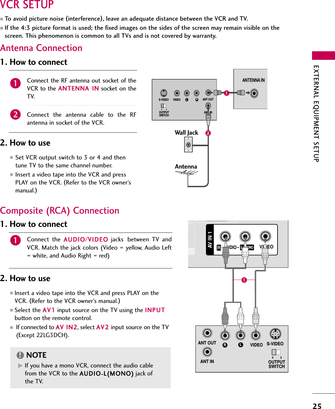
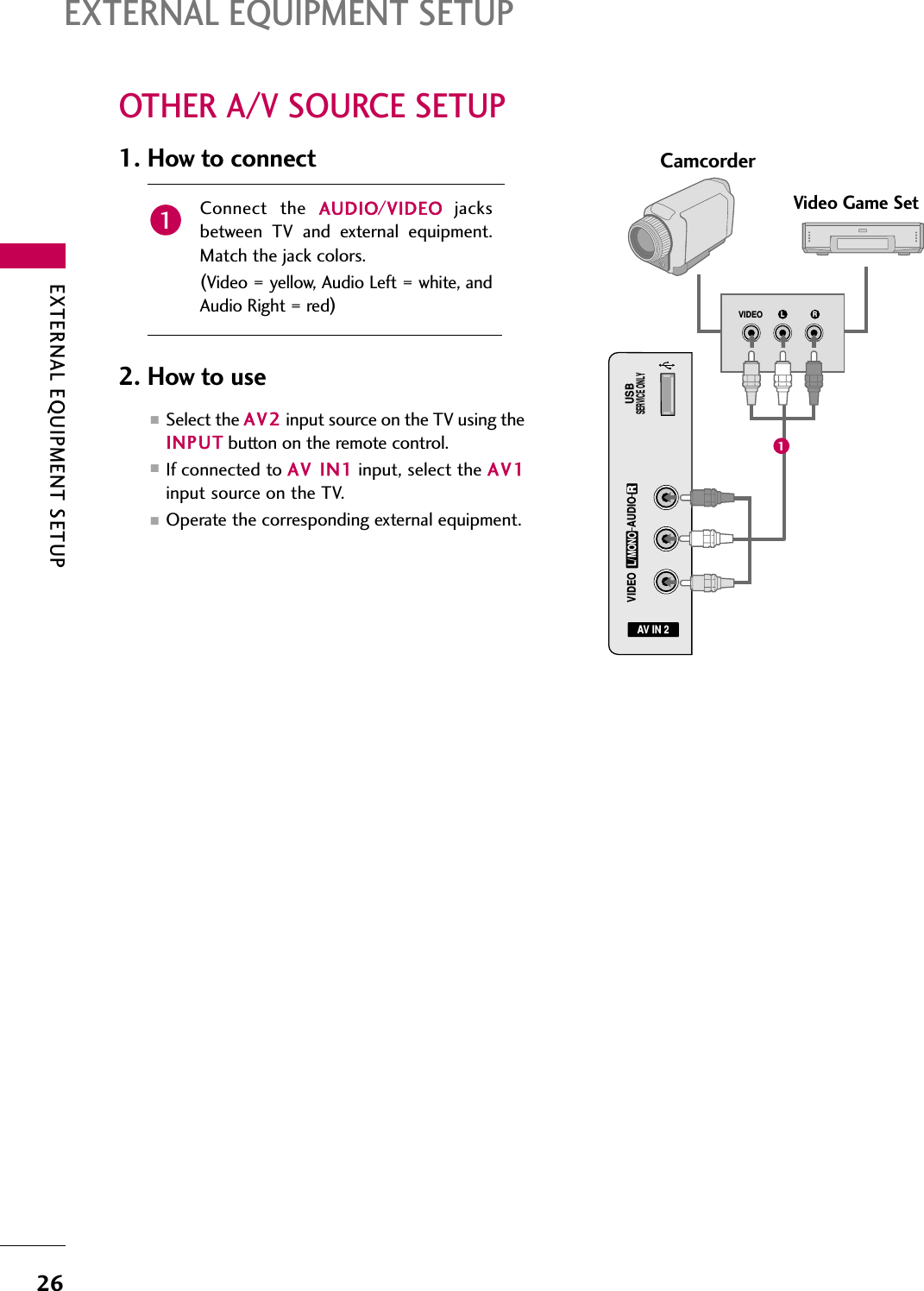
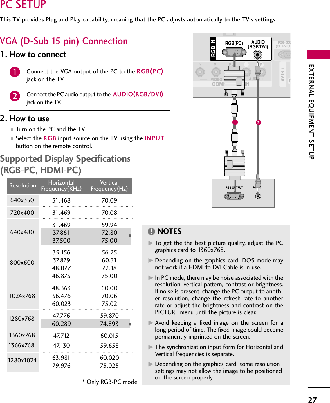
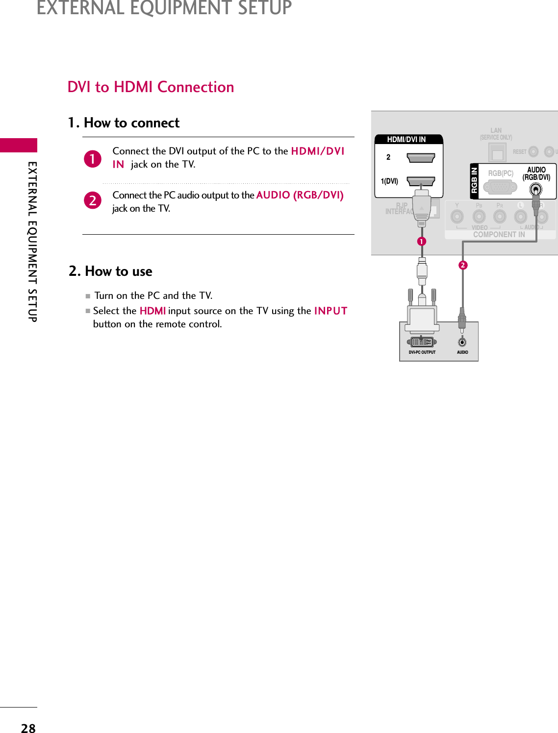
LG Electronics USA 32LG700HUA LCD TV MONITOR User Manual User s Manual H ok
LG Electronics USA LCD TV MONITOR User s Manual H ok
UserManual.wiki
>
LG Electronics USA
>
32LG700HUA User Manual
Users Manual
Navigation menu
Upload a User Manual
Namespaces
Wiki Guide
HTML
PDF
Info
Views
User Manual
Discussion / Help
Navigation
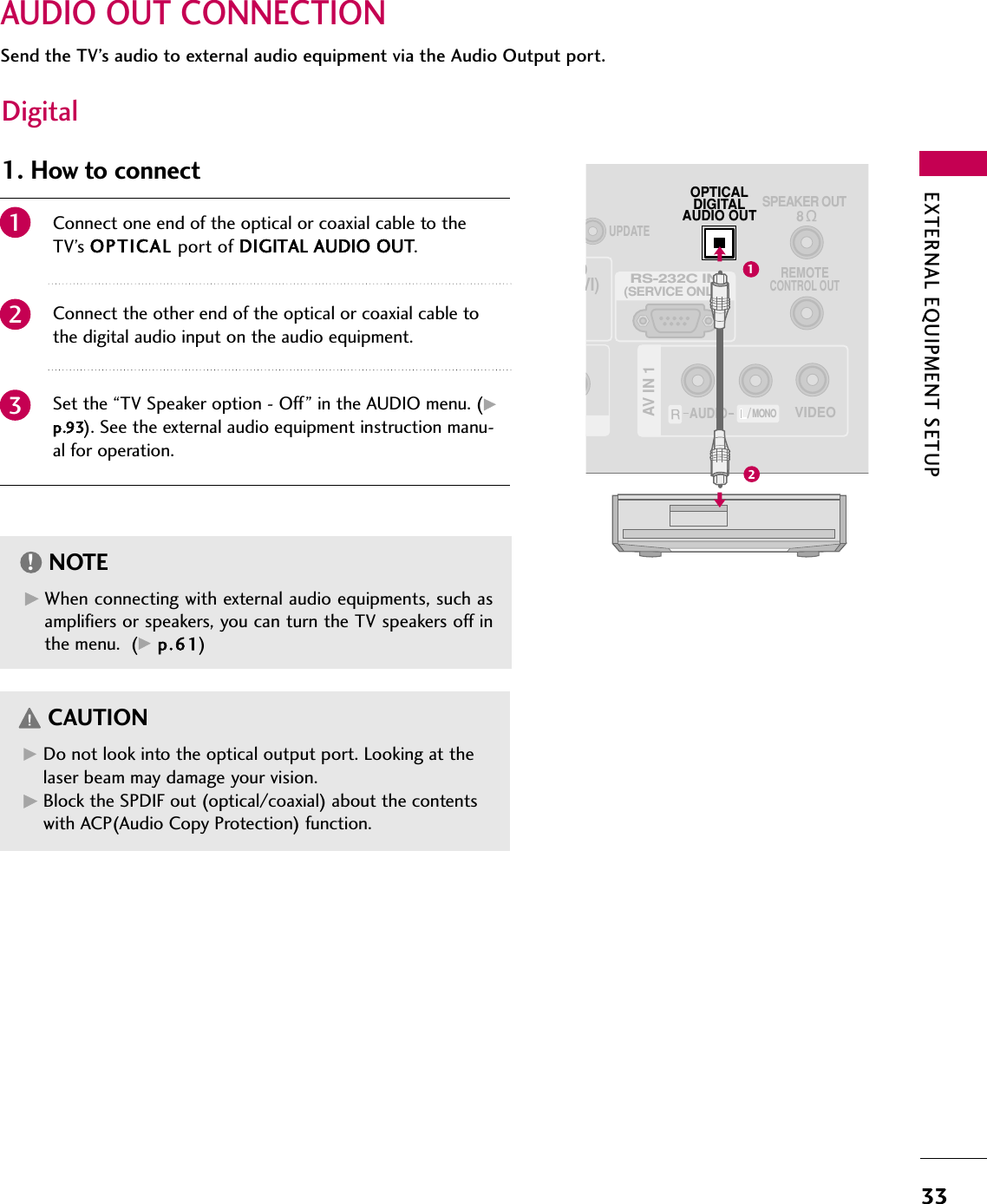
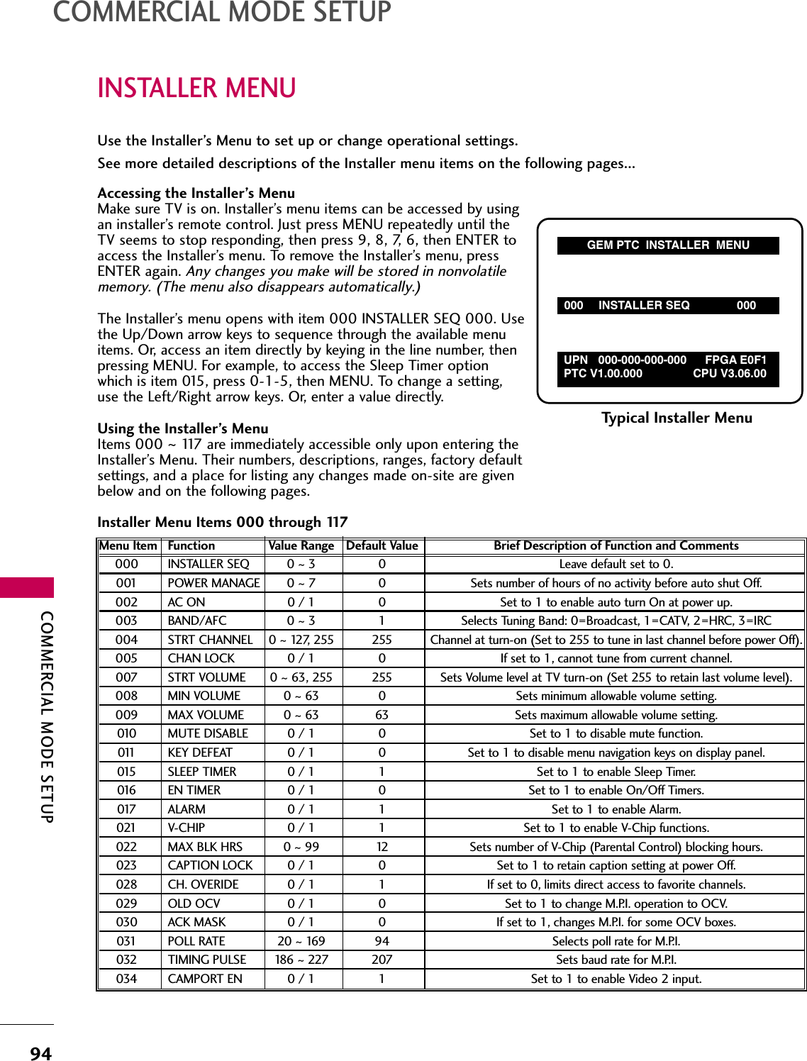
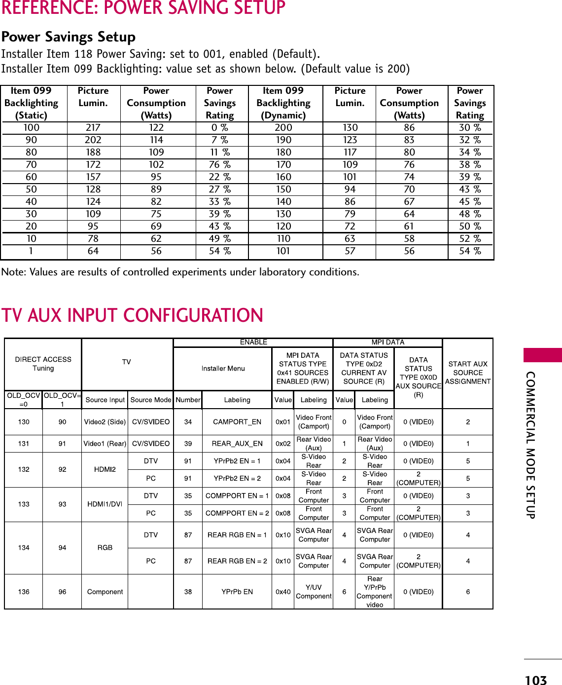
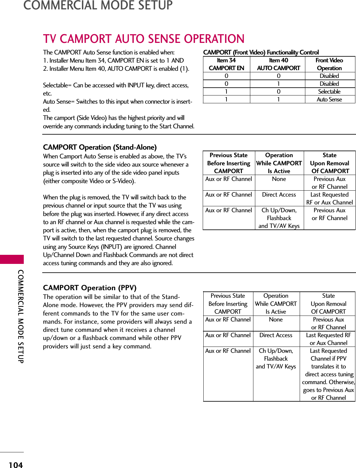
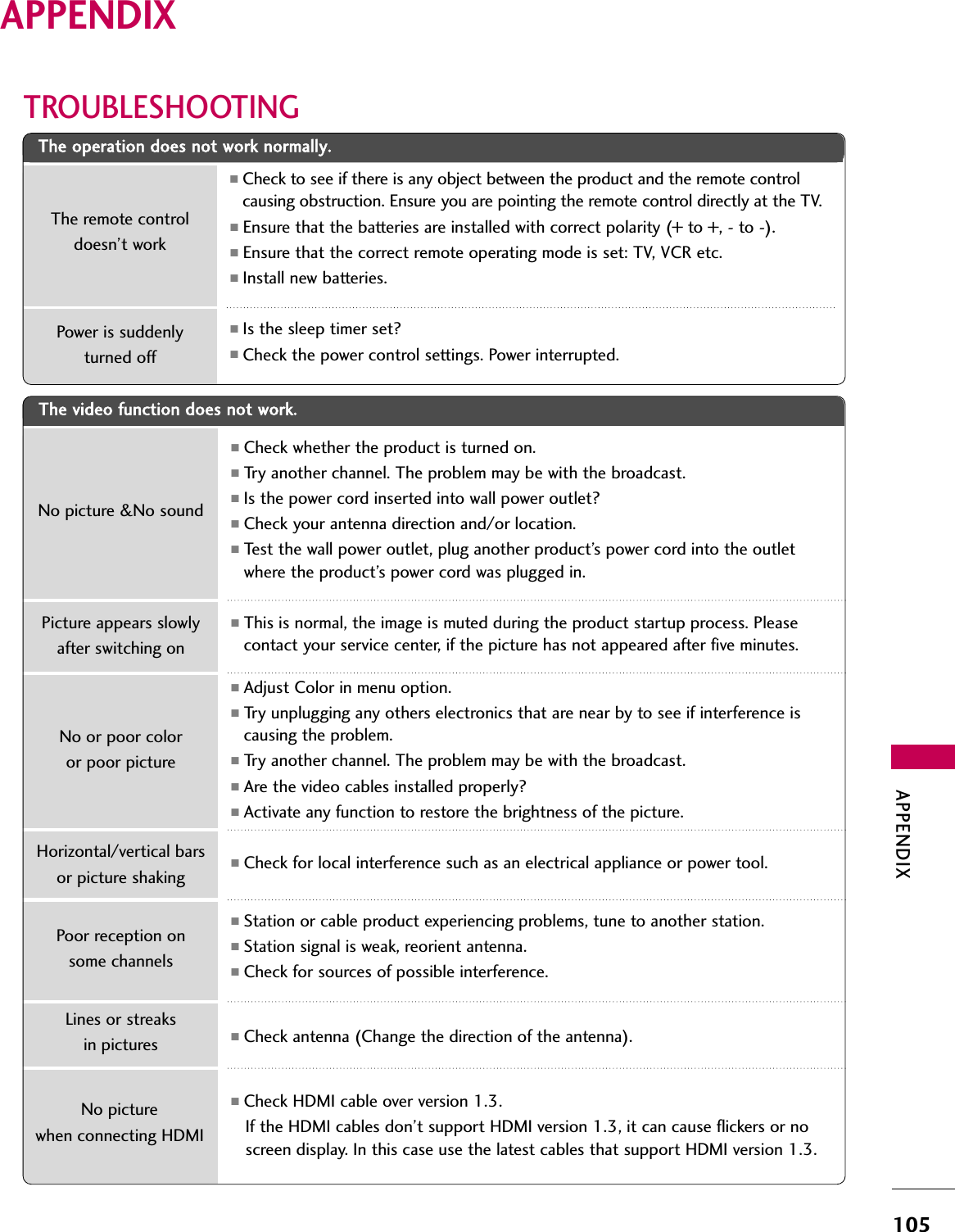
![COMMERCIAL MODE SETUP98COMMERCIAL MODE SETUP0 = Black 3 = Yellow 6 = Cyan1 = Red 4 = Blue 7 = White2 = Green 5 = VioletNOTE: If foreground and background color are thesame, menu background is transparent.073 - CH NOT AVBLE (Channel Not Available)If set to 1 and item 028 CHANNEL OVERRIDE is set to0, “NOT AVAILABLE” message is displayed when directlyaccessing a channel not in the channel scan list availablein memory.075 - REVERT CH (Revert to Start Channel)If set to 1 and loss of M.P.I. communication occurs, TVautomatically tunes to the specified Start Channel.078 - UPN MSB (UPN Most Significant Byte)User programmable number, most significant byte read-able by M.P.I. command. Note: Not linked to serial num-ber.079 - UPN MSB-1 (UPN Most Significant Byte-1)User programmable number, most significant byte-1readable by M.P.I. command. Not linked to serial number.080 - UPN MSB-2 (UPN Most Significant Byte-2)User programmable number, most significant byte-2readable by M.P.I. command. Not linked to serial number.081 - UPN LSB (UPN Least Significant Byte)User programmable number, least significant byte read-able by M.P.I. command. Not linked to serial number.082 - CHKSM ERROR (Checksum Error)Enforces rigid M.P.I. checksum validation.Set to 1 for validation. Set to 0 to disable (does not check checksum on M.P.I.async port). SPI is always checked.083 - HANDSHK TIME (Handshake Time)Adds an additional delay to the handshake time which is64 msec, thus relaxing M.P.I. timing requirements to becompatible with PC based Windows controlled systems,range is 0 - 5. (Timeout = 25.5MS + [25.5 MS* Handshake time]).084 - PERMANENT BLK (Permanent Block)Allows Lock (Parental Control) blocking schemes to bepermanent by disabling the blocking hours function. Set to 1 to install Parental Control restrictions perma-nently. Set to 0 for user-specified hours control of blockingschemes.040 - AUTO CAMPORTSet to 1 to automatically switch to Camport whenequipment is connected to front Video input.Set to 0 to disable front Video automatic source selec-tion.NOTE: If set to 1, 093 RJP Available is automatically setto 0.046 - STRT AUX SRCE (Start Aux Source)Sets the starting AUX source. At power up, TV will tuneto starting Aux source if item 004 Start Channel is setto 0.If item 093 RJP Available is set to 0 and item 040 Auto Camport is set to 0:1 = Video 1 4 = RGB 255 = Last Aux2 = Video 2 5 = HDMI 23 = HDMI 1 6 = ComponentIf item 093 RJP Available is set at 1:2 = Video 2 5 = HDMI 2 6 = ComponentIf item 040 Auto Camport is set to 1:1 = Video 1 5 = HDMI 23 = HDMI 1 6 = Component4 = RGB047 - AUX STATUSSet to 1 for M.P.I. AUX source to be reported as a chan-nel number instead of channel 0. Set to 0 to disableAUX identification change. Controls M.P.I. status channelresponse for AUX inputs.053 - DIS. CH-TIME (Disable Channel-Time)Set to 1 to disable the Channel-Time display, Channel-Time display will not appear.Set to 0 to enable the Channel-Time display.069 - EN. CH-T COL. (Enable Channel-Time CustomColor)Set to 1 to enable custom color for the Channel-Timedisplay.Set to 0 to disable custom color for the Channel-Timedisplay.070 - FOR. CH-TIME (Channel-Time DisplayForeground Color)Set according to Color Chart.0 = Black 3 = Yellow 6 = Cyan1 = Red 4 = Blue 7 = White2 = Green 5 = VioletNOTE: If foreground and background color are thesame, menu background is transparent.071 - BCK. CH-TIME (Channel-Time DisplayBackground Color)Set according to Color Chart.](https://usermanual.wiki/LG-Electronics-USA/32LG700HUA/User-Guide-1054192-Page-54.png)