LG Electronics USA 32LP1DA 32" LCD TV/MONITOR User Manual User s Manual H
LG Electronics USA 32" LCD TV/MONITOR User s Manual H
USERS MANUAL

EUT Type: 32” LCD TV/Monitor
FCC ID: BEJ32LP1DA
Test Report No.: GETEC-E3-05-008
FCC Class B Certification
APPENDIX H
: USER’S MANUAL
Please read this manual carefully before operating your set.
Retain it for future reference.
Record model number and serial number of the set.
See the label attached on the back cover and quote
this information to your dealer
when you require service.
P/NO : 3828TUL298C(0411-REV00)
Printed in Korea
Digital LCD TV
OWNER’S MANUAL 32LP1DC
Warning
WARNING:
TO REDUCE THE RISK OF ELECTRIC SHOCK DO NOT REMOVE COVER (OR BACK). NO USER
SERVICEABLE PARTS INSIDE. REFER TO QUALIFIED SERVICE PERSONNEL.
The lightning flash with arrowhead symbol, within an equilateral triangle, is intended to alert the user to
the presence of uninsulated “dangerous voltage” within the product’s enclosure that may be of suffi-
cient magnitude to constitute a risk of electric shock to persons.
The exclamation point within an equilateral triangle is intended to alert the user to the presence of
important operating and maintenance (servicing) instructions in the literature accompanying the appli-
ance.
NOTE TO CABLE/TV INSTALLER:
This reminder is provided to call the CATV system installer’s attention to Article 820-40 of the National Electric
Code (U.S.A.). The code provides guidelines for proper grounding and, in particular, specifies that the cable
ground shall be connected to the grounding system of the building, as close to the point of the cable entry as prac-
tical.
REGULATORY INFORMATION
This equipment has been tested and found to comply with the limits for a Class B digital device, pursuant to Part
15 of the FCC Rules. These limits are designed to provide reasonable protection against harmful interference in
a residential installation. This equipment generates, uses and can radiate radio frequency energy and, if not
installed and used in accordance with the instructions, may cause harmful interference to radio communications.
However, there is no guarantee that interference will not occur in a particular installation. If this equipment does
cause harmful interference to radio or television reception, which can be determined by turning the equipment off
and on, the user is encouraged to try to correct the interference by one or more of the following measures:
- Reorient or relocate the receiving antenna.
- Increase the separation between the equipment and receiver.
- Connect the equipment into an outlet on a circuit different from that to which the receiver is connected.
- Consult the dealer or an experienced radio/TV technician for help.
Any changes or modifications not expressly approved by the party responsible for compliance could void the
user’s authority to operate the equipment.
CAUTION:
Do not attempt to modify this product in any way without written authorization from LG Electronics Corporation.
Unauthorized modification could void the user’s authority to operate this product.
U.S.A. only -----------------------------------------------
COMPLIANCE:
The responsible party for this product’s compliance is:
LG Electronics U.S.A., Inc.
1000 Sylvan Avenue, Englewood Cliffs, NJ 07632
Phone: 1-201-816-2000
http://www.lgusa.com
---------------------------------------------------------------
CAUTION
RISK OF ELECTRIC SHOCK
DO NOT OPEN
W
Warning
arning
Safety Instructions
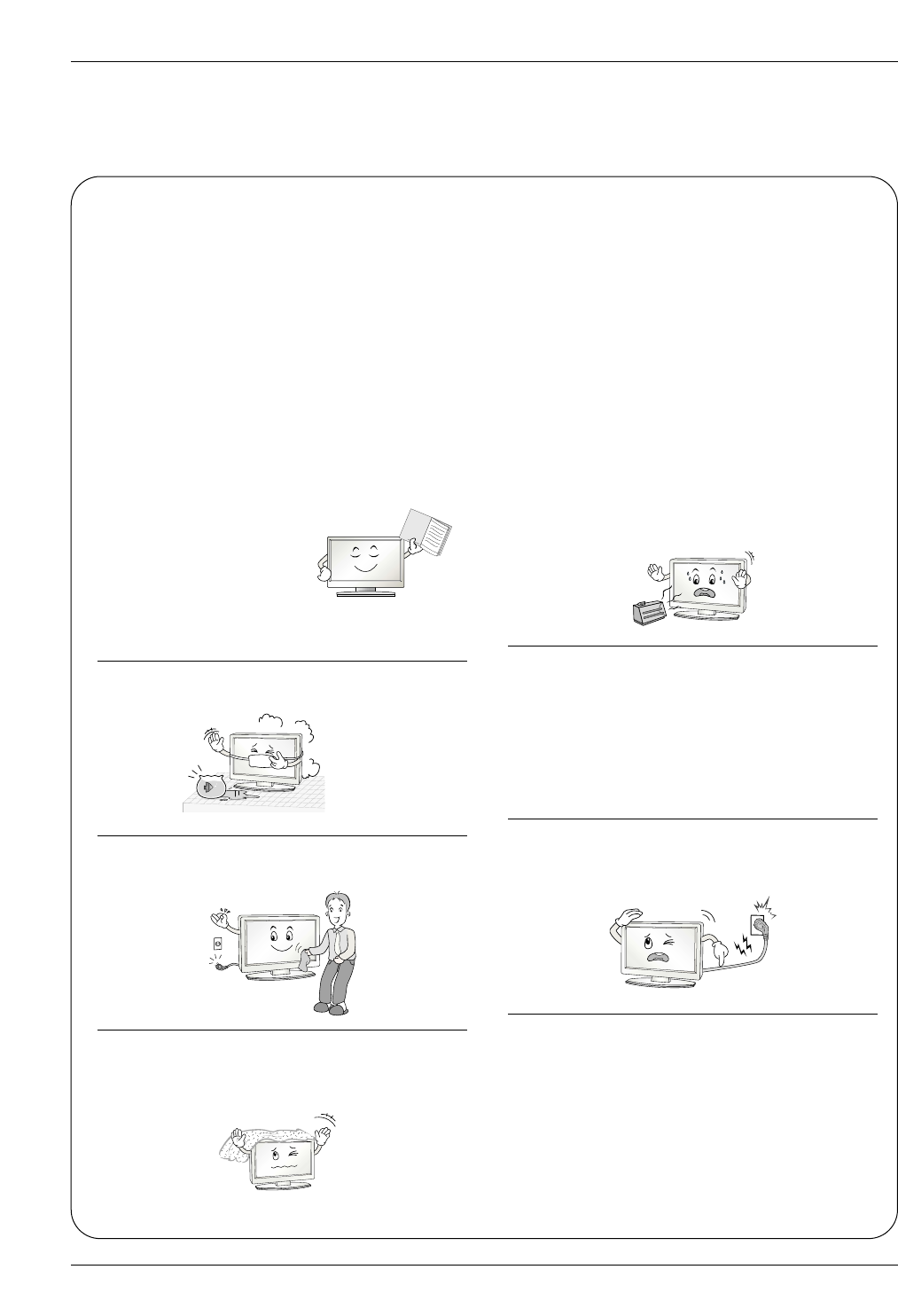
WARNING :
To Reduce The Risk Of Fire Or Electric Shock, Do Not Expose This Apparatus To Rain Or Moisture.
Apparatus shall not be exposed to dripping or splashing and no objects filled with liquids, such as vases, shall be placed on the
apparatus.
IMPORTANT SAFETY INSTRUCTIONS
1. Read these instructions.
2. Keep these instructions.
3. Heed all warnings.
4. Follow all instructions.
5. Do not use this apparatus near water.
6. Clean only with a dry cloth.
7. Do not block any of the ventilation openings. Install in
accordance with the manufacturer’s instructions.
8. Do not install near any heat sources such as radiators,
heat registers, stoves, or other apparatus (including ampli-
fiers) that produce heat.
9. Do not defeat the safety purpose of the polarized or
grounding type plug. A polarized plug has two blades with
one wider than the other. A grounding type plug has two
blades and a third grounding prong. The wide blade or the
third prong is provided for your safety. When the provided
plug does not fit into your outlet, consult an electrician for
replacement of the obsolete outlet.
10. protect the power cord from being walked on or
pinched particularly at plugs, convenience receptacles,
and the point where they exit from the apparatus.
11. Only use the attachments / accessories specified by
the manufacturer.
Safety Instructions
Safety Instructions
Owner's Manual
Safety Instructions
Safety Instructions continued
Safety Instructions continued
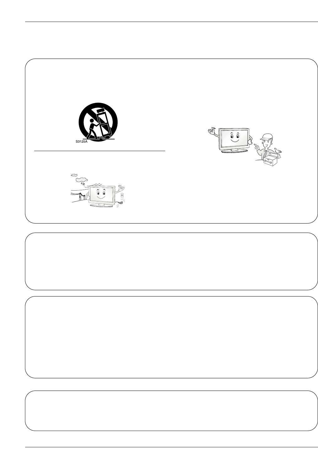
12. Use only with a cart, stand, tripod, bracket, or table
specified by the manufacturer, or sold with the apparatus.
When a cart is used, use caution when moving the cart /
apparatus combination to avoid injury from tip-over.
13. Unplug this apparatus during lightning storms or when
unused for long periods of time.
14. Refer all servicing to qualified service personnel.
Servicing is required when the apparatus has been dam-
aged in any way, such as power supply cord or plug is
damaged, liquid has been spilled or objects have fallen
into the apparatus, the apparatus has been exposed to
rain or moisture, does not operate normally, or has been
dropped.
On Disposal
a. The fluorescent lamp used in this product contains a small amount of mercury.
b. Do not dispose of this product with general household waste.
Disposal of this product must be carried out in accordance to the regulations of your local authority.
Note
- If the TV feels cold to the touch, there may be a small “flicker” when when it is turned on. This is normal, there is noth-
ing wrong with TV.
- Some minute dot defects may be visible on the screen, appearing as tiny red, green, or blue spots. However, they have
no adverse effect on the monitor's performance.
- Avoid touching the LCD screen or holding your finger(s) against it for long periods of time. Doing so may produce some
temporary distortion effects on the screen.
CAUTION concerning the Power Cord
Most appliances recommend they be placed upon a dedicated circuit; that is, a single outlet circuit which powers only that
appliance and has no additional outlets or branch circuits. Check the specification page of this owner's manual to be certain.
Do not overload wall outlets. Overloaded wall outlets, loose or damaged wall outlets, extension cords, frayed power cords,
or damaged or cracked wire insulation are dangerous. Any of these conditions could result in electric shock or fire.
Periodically examine the cord of your appliance, and if its appearance indicates damage or deterioration, unplug it, discon-
tinue use of the appliance, and have the cord replaced with an exact replacement part by an authorized servicer.
Protect the power cord from physical or mechanical abuse, such as being twisted, kinked, pinched, closed in a door, or
walked upon. Pay particular attention to plugs, wall outlets, and the point where the cord exits the appliance.
Controls
Controls
Introduction
Introduction
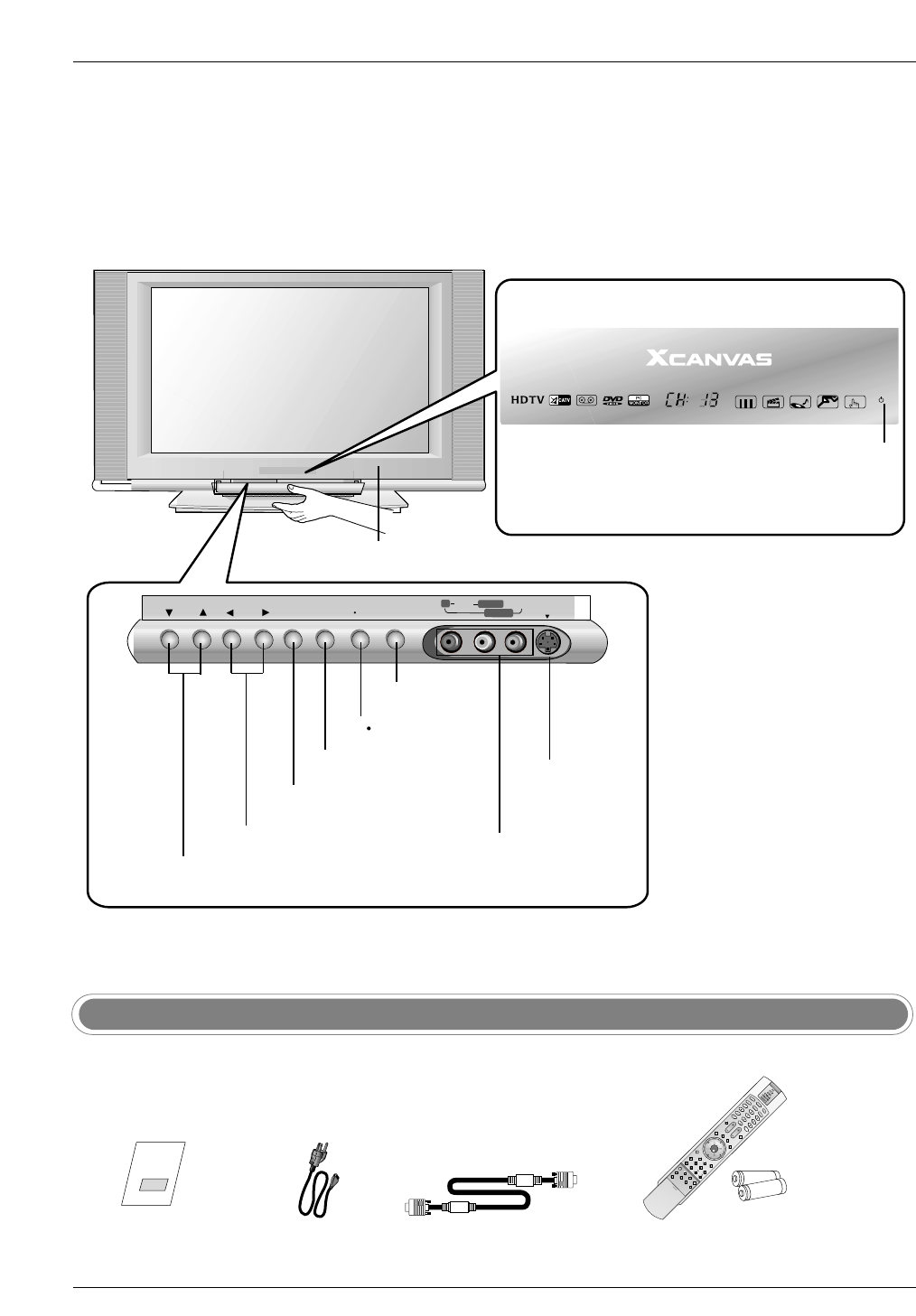
- This is a simplified representation of front panel.
- Here shown may be somewhat different from your TV.
CH VOL ENTER MENU ON/OFF
RRAUDIOAUDIO VIDEOVIDEO S-VIDEOS-VIDEO
L/MONOL/MONO
VIDEO2
TV VIDEO
VOLUME (F,G) Buttons
Power Standby Indicator
Illuminates red when the TV is in standby mode,
illuminates green when the TV is switched on.
Remote Control Sensor
CHANNEL (E,D) Buttons
MENU Button
ENTER Button
ON/OFF Button
Owner’s Manual
Power Cord
D-sub 15 pin Cable
S-VIDEO Input
Audio/Video Input 2
TV VIDEO Button
Ensure that the following accessories are included with your TV. If any accessory is missing, please contact the
dealer from where you purchased the product.
Accessories
1.5V
1.5V
LIGHT
TV/VIDEO
MODE
COMP/RGB/DVI
MUTE SURF
VOL CH
INFO
SAP RATIO
CC
MENU
SOUND VIDEO
EXIT
PLAY PAUSE STOP RECORD
PIP PIPCH- PIPCH+ PIPINPUT
FREEZE
ADJUST
ENTER
ZOOM SIGNAL SWAP
REW FF SKIP
POWER
TIMER
FLASHBK
Remote Control /
AA Batteries
Connection Options
Connection Options
RL
COMPONENT2
VIDEO
Antenna
PC AUDIO
INPUT2
DIGITAL AUDIO
(OPTICAL)
PC INPUT2 DVI INPUT
RJP INTERFACE
L/MONO
INPUT
OUTPUT
PC INPUT1
UPGRADE PORT
AUDIO INPUT
AUDIO VIDEO
VIDEO INPUT
VIDEO1
COMPONENT1
RL
R
PC AUDIO
INPUT1
SPEAKER
OUT
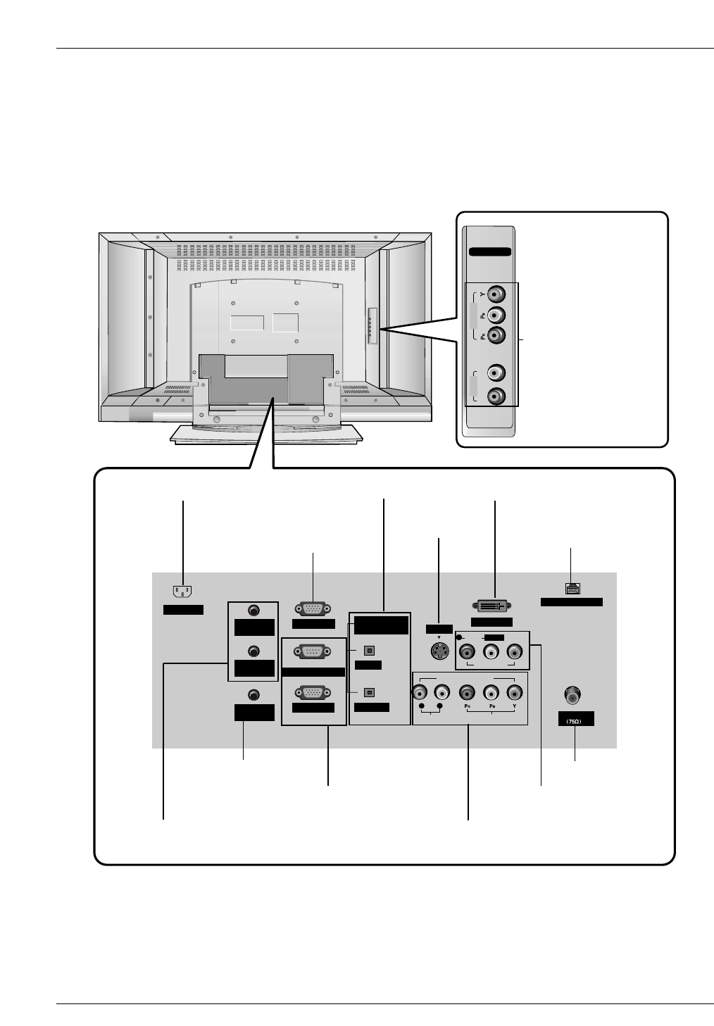
AC INPUT
S-VIDEO
AUDIO
DIGITAL AUDIO INPUT/ OUTPUT
* PC INPUT2
(For service)
AUDIO/VIDEO INPUT1
COMPONENT1 (Y, PB, PR/ AUDIO INPUT)
COMPONENT2 INPUT
(Y, PB, PR/ Audio Input)
S-VIDEO INPUT
DVI INPUT
ANTENNA INPUT
Power Cord Socket
PC AUDIO INPUT1
* PC AUDIO INPUT2 / SPEAKER OUT
(For service)
* For Service Jacks: PC INPUT2, PC AUDIO INPUT2, SPEAKER OUT, and RJP INTERFACE
Be careful not to use this jack. Just contact your dealer or service center.
PC INPUT1/ UPGRADE PORT
* RJP INTERFACE
(For service)
Introduction
Installation
Installation
Various Installation
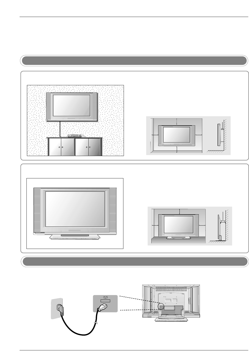
AC INPUT
- Connect the power cord correctly as shown.
Power Cord Connection
4 inches
4 inches
4 inches4 inches
2 inches
For proper ventilation, allow a clearance of 4" on each side
and 2" from the wall. Detailed installation instructions are
available from your dealer, see the optional Tilt Wall
Mounting Bracket Installation and Setup Guide.
Wall Mount: Horizontal installation
Desktop Pedestal Installation
4 inches
4 inches4 inches
2 inches
For proper ventilation, allow a clearance of 4" on each side
and the top, and 2" from the wall.
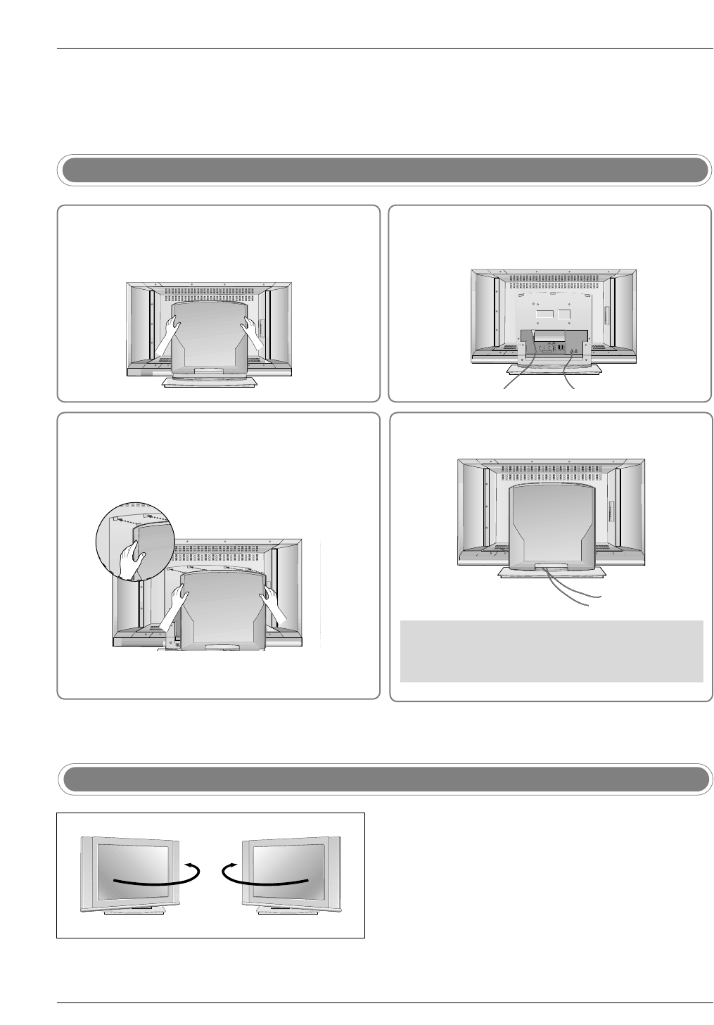
How to use rear AV cover
- The TV can be conveniently swiveled on its stand 90° to
the left or right to provide the optimum viewing angle.
Swivel Stand
34
2
Antenna
LOOP THROUGH
UPGRADE
PORT
HDMI MONITOR
OUT
REMOTE
CONTROL
DVI INPUT
(PC INPUT)
PC SOUND
AV1 AV2
VIDEO
L
AUDIO
R
Install wires as necessary.
(To install various wires, refer to p.14~20.)
Align the holes on the TV back panel with the
four protuberance on the rear AV cover and
insert.
Antenna
LOOP THROUGH
UPGRADE
PORT
HDMI MONITOR
OUT
REMOTE
CONTROL
DVI INPUT
(PC INPUT)
PC SOUND
AV1 AV2
VIDEO
L
AUDIO
R
Reinstall the cover such as open it.
Antenna
LOOP THROUGH
UPGRADE
PORT
HDMI MONITOR
OUT
REMOTE
CONTROL
DVI INPUT
(PC INPUT)
PC SOUND
AV1 AV2
VIDEO
L
AUDIO
R
Wire Arrangement
- Pull the cables through the hole on the set.
Antenna
LOOP THROUGH
UPGRADE
PORT
HDMI MONITOR
OUT
REMOTE
CONTROL
DVI INPUT
(PC INPUT)
PC SOUND
AV1 AV2
VIDEO
L
AUDIO
R
Hold the cover with both hands and pull it
backward.
1
Installation
NOTE: If you are not sure of the type of signal(s) you are receiving, let EZ Scan complete all the channel signal-
type searches. The TV will let you know when the analog, cable, and digital channel scans are complete.
External Equipment Connections
External Equipment Connections
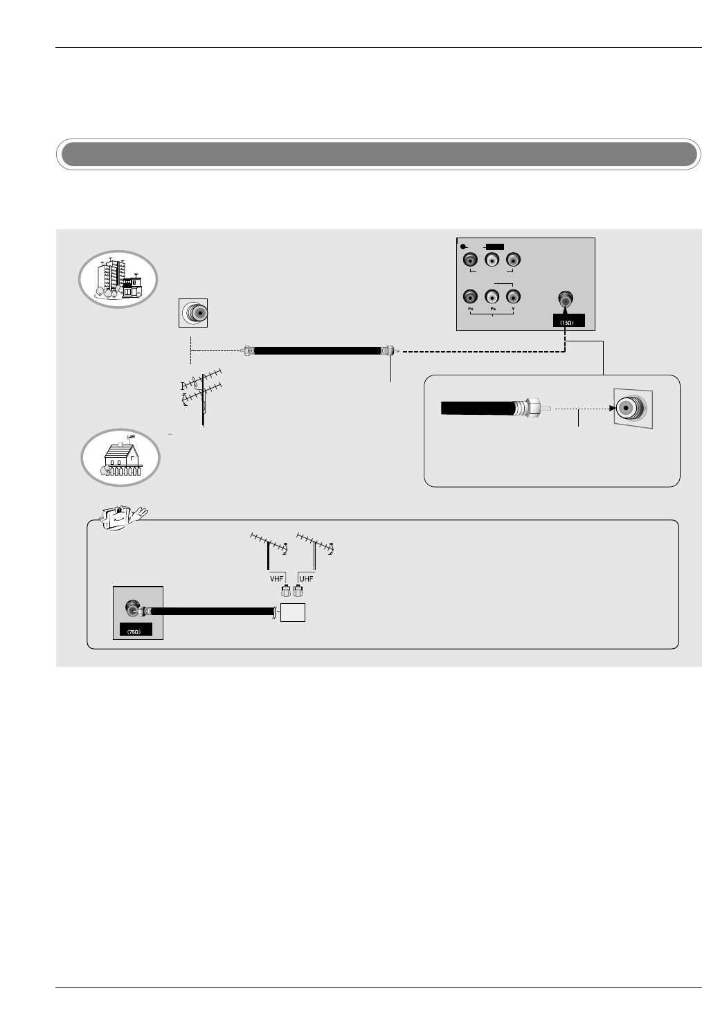
Antenna Connection
- Antenna or Cable Service without a Cable Box Connections
- For optimum picture quality, adjust antenna direction if needed.
Multi-family Dwellings/Apartments
(Connect to wall antenna socket)
Single-family Dwellings /Houses
(Connect to wall jack for outdoor antenna)
Outdoor Antenna
Wall Antenna Socket
VHF Antenna
UHF Antenna
RF Coaxial Wire (75 ohm)
Turn clockwise to tighten.
• In a poor signal area to improve picture quality, purchase
and install a signal amplifier.
• If the antenna needs to be split for two TV’s, install a “2-
Way Signal Splitter” in the connections.
• If the antenna is not installed properly, contact your deal-
er for assistance.
Antenna
Signal
Amplifier
Antenna
L/MONO
U
T
AUDIO VIDEO
VIDEO INPUT
VIDEO1
M
PONENT1
R
Bronze Wire
Be careful not to bend the bronze wire when
connecting the antenna.
Installation
Digital Audio Output
RAUDIO VIDEO S-VIDEO
L/MONO
VIDEO2
RL
AUDIO VIDEO
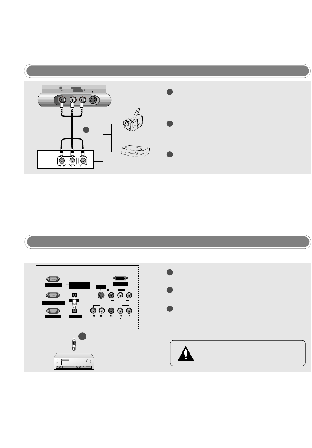
Camcorder
Video Game Set
TV front 1
1
2
3
Connect the AUDIO/VIDEO jacks between TV
and external equipment. Match the jack colours
(Video = yellow, Audio Left = white, and Audio
Right = red).
Select Video 2 input source with using the
TV/VIDEO button on the remote control.
- If connected to VIDEO1 input (the back side),
select Video 1 input source.
Operate the corresponding external equipment.
Refer to external equipment operating guide.
1
2
3
Connect one end of an optical cable to the TV
Digital Audio Optical Output port.
Connect the other end of the optical cable to the
digital audio optical input on the audio equipment.
Set the “ TV Speaker option - Off” in the AUDIO
menu. Refer to page 35.
See the external audio equipment instruction
manual for operation.
DIGITAL AUDIO
(OPTICAL)
PC INPUT2 DVI INPUT
L/MONO
INPUT
OUTPUT
PC INPUT1
UPGRADE PORT
AUDIO INPUT
AUDIO VIDEO
VIDEO INPUT
VIDEO1
COMPONENT1
RL
R
S-VIDEO
- Send the TV’s audio to external audio equipment (stereo system) via the Digital Audio Output Optical port.
CAUTION
Do not look into the optical output port. Looking
at the laser beam may damage your vision.
External AV Source Setup
1/2 TV Back
Installation
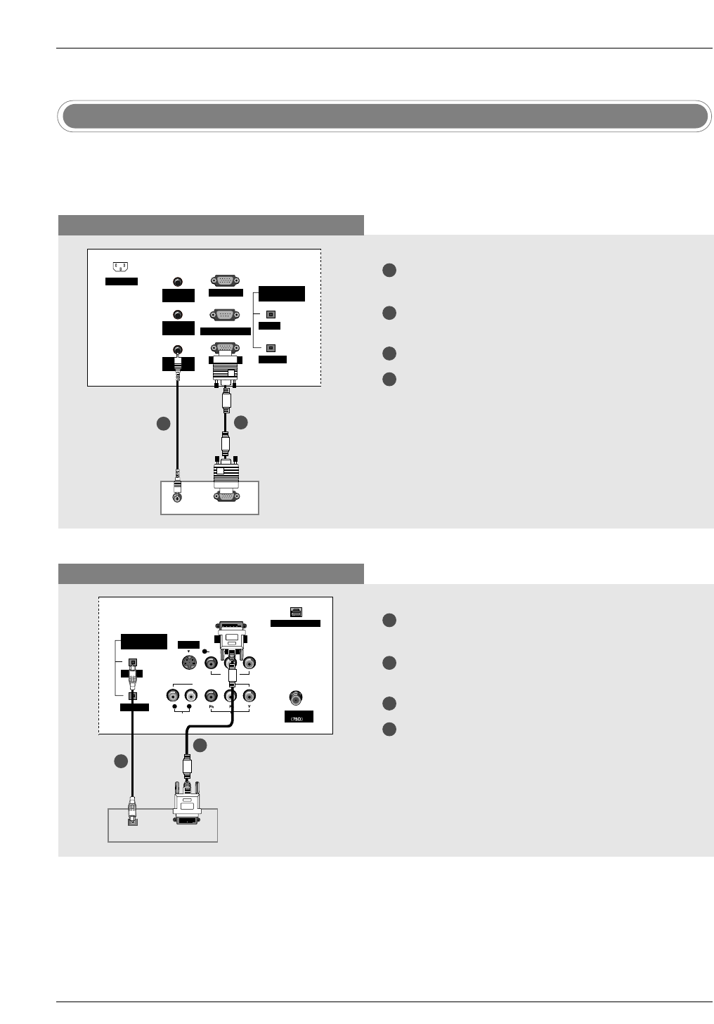
- This TV provides Plug and Play capability, meaning that the PC adjusts automatically to the TV's settings.
The TV sends configuration information (EDID) to the PC using the Video Electronics Standard Association
(VESA) Display Data Channel (DDC) protocol.
PC Setup
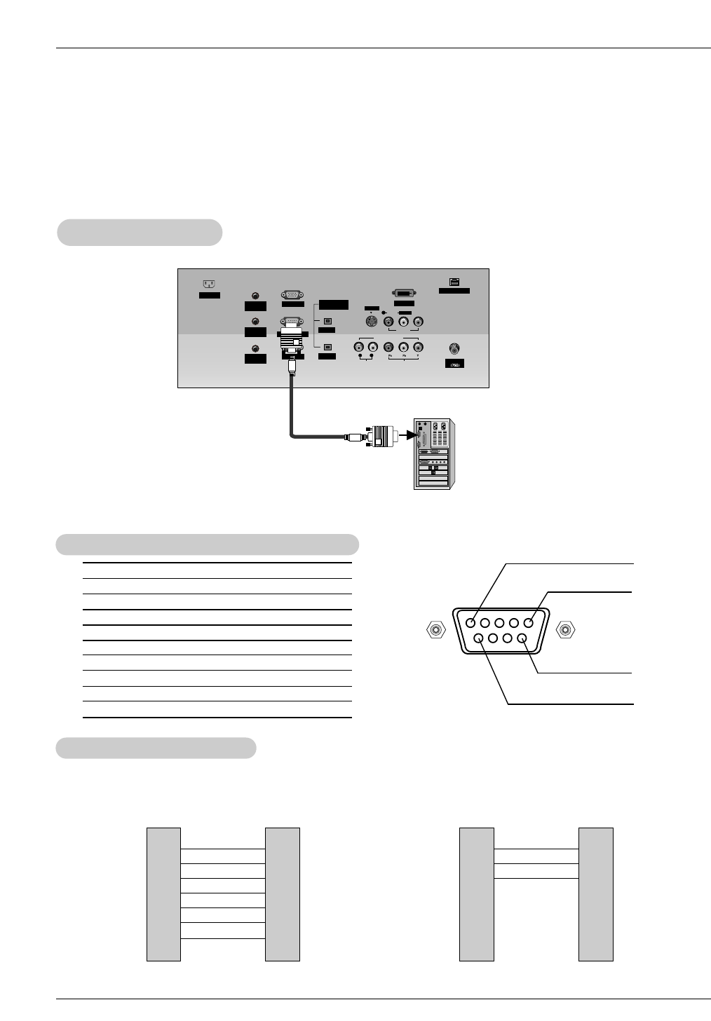
When connecting with a D-sub 15 pin cable
When connecting with a DVI cable
1
2
3
4
Connect the RGB output of the PC to the PC
INPUT1 jack on the set.
Connect the PC audio outputs to the PC AUDIO
INPUT1 jack on the set.
Turn on the PC and the set.
Select RGB1-PC input source in main input
option of SETUP menu. (Refer to P.28)
1
2
3
4
Connect the DVI output of the PC to the DVI
INPUT jack on the set.
Connect the PC audio outputs to the DIGITAL
AUDIO INPUT jack on the set.
Turn on the PC and the set.
Select DVI-PC input source in main input option
of SETUP menu. (Refer to P.28)
Antenna
DIGITAL AUDIO
(OPTICAL)
DVI INPUT
RJP INTERFACE
L/MONO
INPUT
OUTPUT
AUDIO INPUT
AUDIO VIDEO
VIDEO INPUT
VIDEO1
COMPONENT1
RL
R
S-VIDEO
DVI-PC OUPUT
DIGITAL AUDIO
OPTICAL
PC AUDIO
INPUT2
DIGITAL AUDIO
(OPTICAL)
PC INPUT2
INPUT
OUTPUT
PC INPUT1
UPGRADE PORT
PC AUDIO
INPUT1
SPEAKER
OUT
AC INPUT
RGB-PC OUPUT
AUDIO
1
2
1
2
TV Back
PC
TV Back
PC
Installation
1. To get the best picture quality, adjust the PC graph-
ics card to 1024x768, 60Hz.
2. If the graphic card on the PC does not output ana-
log and digital RGB simultaneously, connect only
one of either PC INPUT or DVI INPUT to display
the PC on the TV.
If the graphic card on the PC does output analog
and digital RGB simultaneously, set the TV to
either RGB or DVI; (the other mode is set to Plug
and Play automatically by the TV.)
3. If using a sound card, adjust the PC sound as
required.
4. Check the image on your TV. There may be noise
associated with the resolution, vertical pattern,
contrast or brightness in PC mode. If noise is pre-
sent, change the PC mode to another resolution,
change the refresh rate to another rate or adjust
the brightness and contrast on the menu until the
picture is clear. If the refresh rate of the PC graphic
card can not be changed, change the PC graphic
card or consult the manufacturer of the PC graphic
card.
5. Avoid keeping a fixed image on the TV's screen for
a long period of time. The fixed image may become
permanently imprinted on the screen.
6. The synchronization input form for Horizontal and
Vertical frequencies is separate.
* DPM (Display Power Management) Mode
When the PC is in the power saving mode, auto-
matically the set goes into DPM mode to save the
energy.
* Use the supplied signal cable with the set. Otherwise,
DPM mode may not work.
Monitor Display Specifications (RGB1-PC / DVI-PC Mode)
Resolution
640x350
720x400
640x480
800x600
1024x768
Horizontal Frequency
(KHz)
31.468
31.469
37.927
31.469
37.861
37.500
35.156
37.879
48.077
46.875
48.363
56.476
60.023
70.09
70.08
85.03
59.94
72.80
75.00
56.25
60.31
72.18
75.00
60.00
70.06
75.02
Vertical Frequency
(Hz)

Operation
1.Press the ZOOM button in DTV 720p, or 1080i modes.
2.Use the D/E/F/Gbuttons to select the screen split zoom section.
3.To return to normal viewing, press the ZOOM button again.
- Enlarges the picture with correct propor-
tions.
- When enlarging the picture, the image
may become distorted.
F
F
F
F
Split Zoom (DTV 720p, or 1080i mode only)
Operation
No. Pin Name
1 No connection
2 RXD (Receive data)
3 TXD (Transmit data)
4 DTR (DTE side ready)
5 GND
6 DSR (DCE side ready)
7 RTS (Ready to send)
8 CTS (Clear to send)
9 No Connection
1
5
6
9
2
3
5
4
6
7
8
RXD
TXD
GND
DTR
DSR
RTS
CTS
TXD
RXD
GND
DSR
DTR
CTS
RTS
PC
7-Wire Configurations
(Standard RS-232C cable)
D-Sub 9
3
2
5
6
4
8
7
TV
D-Sub 9
2
3
5
4
6
7
8
RXD
TXD
GND
DTR
DSR
RTS
CTS
TXD
RXD
GND
DTR
DSR
RTS
CTS
PC
3-Wire Configurations
(Not standard)
D-Sub 9
3
2
5
4
6
7
8
TV
D-Sub 9
- Connect the RS-232C input jack to an external control device (such as a computer or an A/V con-
trol system) and control the Monitor’s functions externally.
- Connect the serial port of the control device to the RS-232C jack on the TV back panel.
- RS-232C connection cables are not supplied with the TV.
T
Type of Connector; D-Sub 9-Pin Male
ype of Connector; D-Sub 9-Pin Male
RS-232C Configurations
RS-232C Configurations
External Control Device Setup
External Control Device Setup
RS-232C Setup
RS-232C Setup
Antenna
PC AUDIO
INPUT2
DIGITAL AUDIO
(OPTICAL)
PC INPUT2 DVI INPUT
RJP INTERFACE
L/MONO
S-VIDEO
INPUT
OUTPUT
PC INPUT1
UPGRADE PORT
AUDIO INPUT
AUDIO VIDEO
VIDEO INPUT
VIDEO1
COMPONENT1
RL
R
PC AUDIO
INPUT1
SPEAKER
OUT
AC INPUT
PC
External Control Device Setup
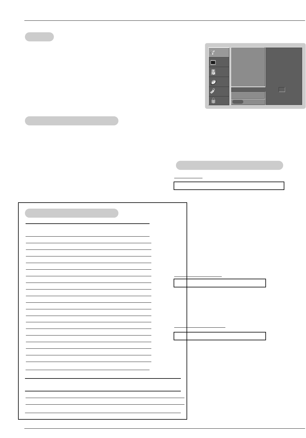
Set ID
Set ID
- Use this function to specify a monitor ID number.
- Refer to ‘Real Data Mapping’. See page 50.
• Baud rate : 9600 bps (UART)
• Data length : 8 bits
• Parity : None
* Use a crossed (reverse) cable.
• Stop bit : 1 bit
• Communication code : ASCII code
Communication Parameters
Communication Parameters
1. Press the MENU button and then use D/Ebutton to select the SETUP menu.
2. Press the Gbutton and then use D/Ebutton to select SET ID.
3. Press the Gbutton and then use D/Ebutton to adjust SET ID to choose the
desired monitor ID number. The adjustment range of SET ID is 1 ~ 99.
4. Press EXIT button to return to TV viewing or press MENU button to return to the
previous menu.
Transmission
*[Command 1]: First command to control the set. (j or k)
*[Command 2]: Second command to control the set.
*[Set ID]: You can adjust the set ID to choose desired monitor
ID number in Setup menu. Adjustment range is 1
~ 99. When selecting Set ID ‘0’, every connected
the TV is controlled. Set ID is indicated as decimal
(1~99) on menu and as Hexa decimal (0x0~0x63)
on transmission/receiving protocol.
*[DATA]: To transmit command data.
Transmit ‘FF’ data to read status of command.
*[Cr]: Carriage Return
ASCII code ‘0x0D’
*[ ]: ASCII code ‘space (0x20)’
[Command1][Command2][ ][Set ID][ ][Data][Cr]
T
Transmission / Receiving Protocol
ransmission / Receiving Protocol
OK Acknowledgement
* The Monitor transmits ACK (acknowledgement) based on
this format when receiving normal data. At this time, if the
data is data read mode, it indicates present status data. If
the data is data write mode, it returns the data of the PC
computer.
[Command2][ ][Set ID][ ][OK][Data][x]
Error Acknowledgement
* The Monitor transmits ACK (acknowledgement) based on
this format when receiving abnormal data from non-viable
functions or communication errors.
[Command2][ ][Set ID][ ][NG][Data][x]
Data 1: Illegal Code
2: Not supported function
3: Wait more time
01. Power k a 0 ~ 1
02. Input Select k b 0 ~ 9
03. Aspect Ratio k c 1 ~ 1F
04. Screen Mute k d 0 ~ 1
05. Volume Mute k e 0 ~ 1
06. Volume Control k f 0 ~ 64
07. Contrast k g 0 ~ 64
08. Brightness k h 0 ~ 64
09. Color k i 0 ~ 64
10. Tint k j 0 ~ 64
11. Sharpness k k 0 ~ 64
12. OSD Select k l 0 ~ 1
13.
Remote Control Lock Mode
k m 0 ~ 1
14. PIP/Twin k n 0 ~ 3
15. PIP Position k q 0 ~ 3
16. Treble k r 0 ~ 64
17. Bass k s 0 ~ 64
18. Balance k t 0 ~ 64
19. Color Temperature k u 0 ~ 2
20. PIP Input Source k y 0 ~ 3
COMMAND 1 COMMAND 2 DATA
(Hexadecimal)
21. Channel Tuning m a 01 ~ 87 01 ~ 87 00 ~ FE 00 ~ 15
22. Channel Add/Del m b 00 ~ 01
23. Key m c
COM-
MAND 2
COM-
MAND 1
DATA 0
(Hexadecimal)
DATA 1
(Hexadecimal)
DATA 2
(Hexadecimal)
DATA 3
(Hexadecimal)
Command Reference List
Command Reference List
SETUP
VIDEO
AUDIO
TIME
OPTION
LOCK Prev.
EZ Scan
Ch.Edit
DTV Signal
Ch. Label
Main Input
Sub Input
Front Display
SET ID G
MENU
1
External Control Device Setup
02. Input Select (Command2:b) (Main Picture Input)
GTo select input source for the TV.
Transmission
Data 0: DTV
1: Analog
2: Video 1
3: Video 2
4: Component 1
5: Component 2
6: RGB-DTV
7: RGB-PC
8: DVI-DTV
9: DVI-PC
Data 1: Normal screen (4:3)
2: Wide screen (16:9)
3: Horizon
4: Zoom 1
5: Zoom 2
6: Auto (Set by program)
10: Cinema Zoom (1)
1F: Cinema Zoom (16)
[k][b][ ][Set ID][ ][Data][Cr]
Acknowledgement
[b][ ][Set ID][ ][OK][Data][x]
01. Power (Command2:a)
GTo control Power On/Off of the TV.
Transmission
Data 0 : Power Off 1 : Power On
[k][a][ ][Set ID][ ][Data][Cr]
Acknowledgement
[a][ ][Set ID][ ][OK][Data][x]
* In a like manner, if other functions transmit ‘FF’ data
based on this format, Acknowledgement data feedback
presents status about each function.
*Real data mapping
0 : Step 0
A : Step 10 (SET ID 10)
F : Step 15 (SET ID 15)
10 : Step 16 (SET ID 16)
64 : Step 100
05. Volume Mute (Command2:e)
GTo control volume mute on/off.
You can also adjust mute using the MUTE button on
remote control.
Transmission
Data 0 : Volume mute off (Volume on)
1 : Volume mute on (Volume off)
[k][e][ ][Set ID][ ][Data][Cr]
Acknowledgement
[e][ ][Set ID][ ][OK][Data][x]
03. Aspect Ratio (Command2:c) (Main picture format)
GTo adjust the screen format.
You can also adjust the screen format using the RATIO
button on remote control or in the Option menu.
Transmission
[k][c][ ][Set ID][ ][Data][Cr]
Acknowledgement
[c][ ][Set ID][ ][OK][Data][x]
04. Screen Mute (Command2:d)
GTo select screen mute on/off.
Transmission
Data 0 : Screen mute off (Picture on)
1 : Screen mute on (Picture off)
[k][d][ ][Set ID][ ][Data][Cr]
Acknowledgement
[d][ ][Set ID][ ][OK][Data][x]
06. Volume Control (Command2:f)
GTo adjust volume.
You can also adjust volume with the volume buttons
on remote control.
Transmission
Data Min : 0 ~ Max : 64
•Refer to ‘Real data mapping’ as shown below.
[k][f][ ][Set ID][ ][Data][Cr]
Acknowledgement
[f][ ][Set ID][ ][OK][Data][x]
07. Contrast (Command2:g)
GTo adjust screen contrast.
You can also adjust contrast in the Video menu.
Transmission
Data Min : 0 ~ Max : 64
•Refer to ‘Real data mapping’ as shown below.
[k][g][ ][Set ID][ ][Data][Cr]
Acknowledgement
[g][ ][Set ID][ ][OK][Data][x]
08. Brightness (Command2:h)
GTo adjust screen brightness.
You can also adjust brightness in the Video menu.
Transmission
Data Min : 0 ~ Max : 64
•Refer to ‘Real data mapping’ as shown below.
[k][h][ ][Set ID][ ][Data][Cr]
Acknowledgement
[h][ ][Set ID][ ][OK][Data][x]
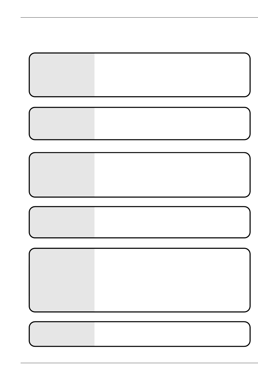
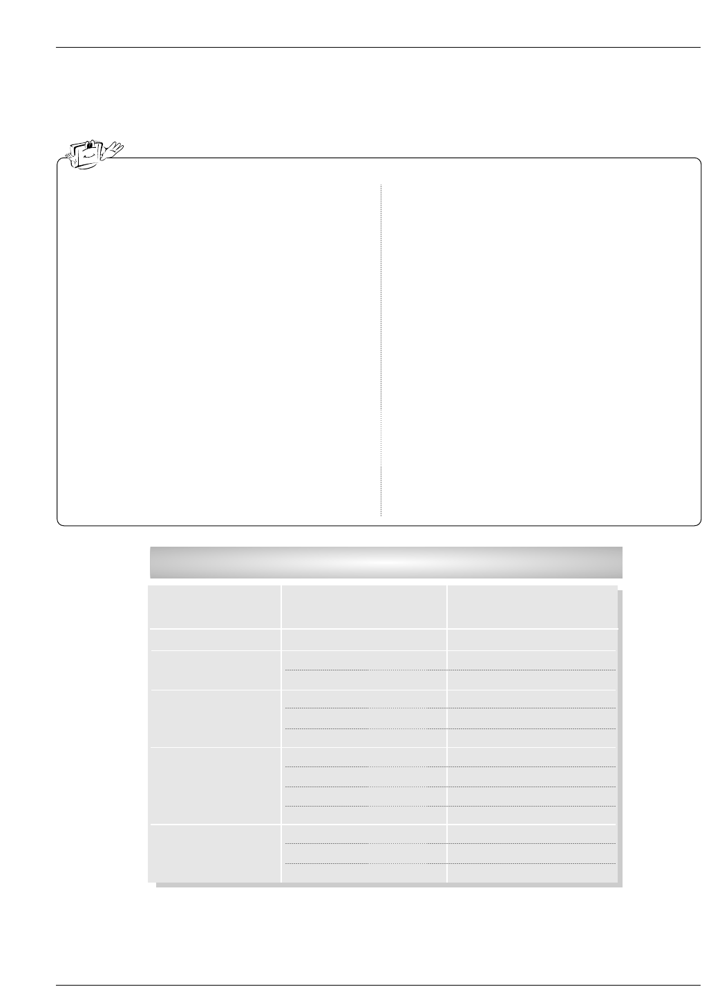
Troubleshooting Checklist
No picture &
No sound
• Check whether the TV is turned on.
• Try another channel. The problem may be with the broadcast.
• Is the power cord inserted into wall power outlet?
• Check your antenna direction and/or location.
• Test the wall power outlet, plug another product’s power cord into the
outlet where the TV’s power cord was plugged in.
No or poor color
or poor picture
• Select Color in the Video menu and press the VOLUME (G) button.
• Keep a sufficient distance between the TV and the VCR.
• Try another channel. The problem may be with the broadcast.
• Are the video cables installed properly?
• Activate any function to restore the brightness of the picture.
(If still picture is on the screen for more than 5 minutes, the screen gets
dark.)
The remote control
doesn’t work
• Check to see if there is any object between the TV and the remote
control causing obstruction.
• Are batteries installed with correct polarity (+ to +, - to -)?
• Correct remote operating mode set: TV, VCR etc.?
• Install new batteries.
Picture OK &
No sound
• Press the VOLUME (G) button.
• Sound muted? Press MUTE button.
• Try another channel. The problem may be with the broadcast.
• Are the audio cables installed properly?
Picture appears slowly
after switching on
• This is normal, the image is muted during the TV startup process.
Please contact your service center, if the picture has not appeared
after five minutes.
Horizontal/vertical
bars or picture shak-
ing
• Check for local interference such as an electrical appliance or power
tool.
T
Troubleshooting Checklist
roubleshooting Checklist
Troubleshooting Checklist
Poor reception on
some channels
• Station or cable TV experiencing problems, tune to another station.
• Station signal is weak, reorient antenna to receive weaker staion.
• Check for sources of possible interference.
Poor stereo sound • Check the kind of input signal and select Mono,Stereo,SAP with
SAP the button.
Lines or streaks in
pictures • Check antenna (Change the direction of the antenna).
Power is suddenly
turned off
• Is the sleep timer set?
• Check the power control settings. /Power interrupted
• No broadcast on station tuned with Auto off activated.
Unusual sound from
inside the TV
• A change in ambient humidity or temperature may result in an
unusual noise when the plasma display is turned on or off and does
not indicate a fault with the TV.
No output from one
of the speakers • Adjust Balance in the AUDIO menu.
Maintenance
1. Here’s a great way to keep the dust off your screen for a while. Wet a soft cloth in a mixture of lukewarm water
and a little fabric softener or dish washing detergent. Wring the cloth until it’s almost dry, and then use it to wipe
the screen.
2. Make sure the excess water is off the screen, and then let it air-dry before you turn on your TV.
To remove dirt or dust, wipe the cabinet with a soft, dry, lint-free cloth.
Please be sure not to use a wet cloth.
If you expect to leave your TV dormant for a long time (such as a vacation), it’s a good idea to
unplug the power cord to protect against possible damage from lightning or power surges.
- Early malfunctions can be prevented. Careful and regular cleaning can extend the amount of time you will have
your new TV. Be sure to turn the power off and unplug the power cord before you begin any cleaning.
Cleaning the Screen
Cleaning the Screen
Cleaning the Cabinet
Cleaning the Cabinet
Extended
Extended Absence
Absence
Maintenance
Maintenance
• The specifications shown above may be changed without prior notice for quality improvement.
Product Specifications
Product Specifications
MODEL
Width (inches / mm)
Height (inches / mm)
Depth (inches / mm)
Weight (pounds / kg)
Power requirement
Television System
Program Coverage
External Antenna Impedance
40.12 / 1019
24.7 / 627.5
8.03 / 204
73.4 / 32
AC 100-240V~ 50/60Hz 2.0A
NTSC-M, ATSC
VHF 2 ~ 13, UHF 14 ~ 69, CATV 1 ~ 125, CADTV 1 ~ 135. DTV 2 ~ 69
75 :
32LP1DC