LG Electronics USA 32LRJ 32" LCD MONITOR User Manual User s Manual H ok
LG Electronics USA 32" LCD MONITOR User s Manual H ok
UserManual.wiki
>
LG Electronics USA
>
32LRJ User Manual
USERS MANUAL
Navigation menu
Upload a User Manual
Namespaces
Wiki Guide
HTML
PDF
Info
Views
User Manual
Discussion / Help
Navigation
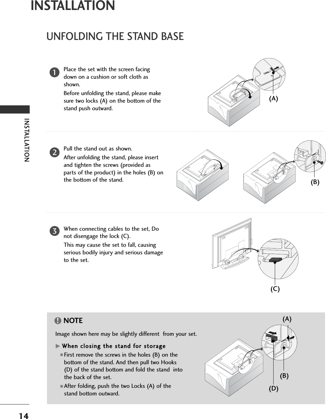
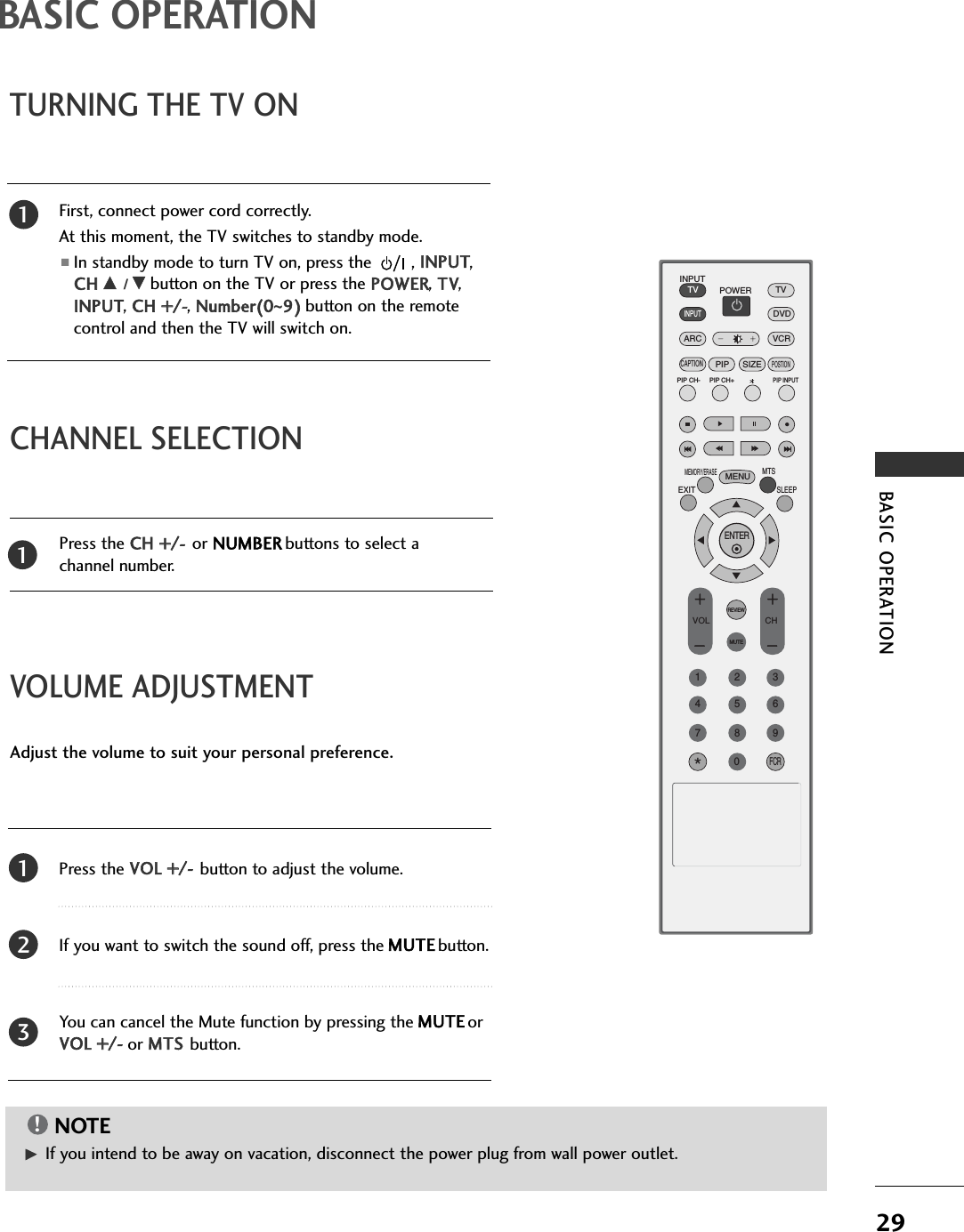
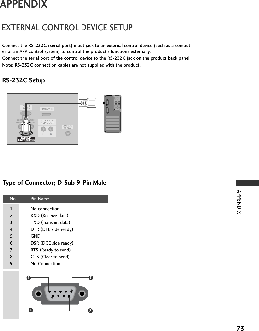
![28CONNECTIONS & SETUPCONNECTIONS & SETUPHorizontal Vertical Frequency(KHz) Frequency(Hz)31.5 70.131.5 70.131.5 59.937.9 60.348.4 60.047.8 59.947.7 59.847.7 59.8Resolution 640x350720x400640x480800x6001024 x 768128 0 x 76 8136 0 x 76 8136 6 x 768Supported Display Resolution (RGB[PC] mode)(26/32LC2R)Supported Display Resolution (RGB[PC] mode)(42PC3RV)Horizontal Vertical Frequency(KHz) Frequency(Hz)31.5 70.131.5 70.131.5 59.931.5 60.031.5 60.037.9 60.348.4 60.0Resolution 640x350720x400640x480848x480852x480800x6001024 x 768NOTE!GTo get the the best picture quality, adjust the PCgraphics card to 640x480, 60Hz (42PC3RV)/1360x768, 60Hz (26/32LC2R).GDepending on the graphics card, DOS mode maynot work if a HDMI to DVI Cable is in use. GWhen Source Devices connected with HDMIInput, output TV SET Resolution (480p, 720p,1080i) and TV SET Display fit EIA/CEA-861-BSpecification to Screen. If not, refer to theManual of HDMI Source Devices or contact yourservice center.GIf the HDMI Source Device is not connected tothe Cable or if there is a poor cable connection,"No signal" is displayed in the HDMI Input. Inthis case, that Video Resolution is not support-ed. If "Invalid Format" is displayed, refer to theSource Device manual or contact your servicecenter.GAvoid keeping a fixed image on the screen for along period of time. The fixed image maybecome permanently imprinted on the screen.GThe synchronization input form for Horizontaland Vertical frequencies is separate.GWhen you use too long RGB-PC cable, theremight be a noise on the screen. We recommendusing under 5m of the cable. It provides the bestpicture quality.GThis set does not support HDMI-PC](https://usermanual.wiki/LG-Electronics-USA/32LRJ/User-Guide-667612-Page-26.png)