LG Electronics USA 37LD650HUA LCD TV Monitor User Manual SAC34134301 Edit1
LG Electronics USA LCD TV Monitor SAC34134301 Edit1
Contents
- 1. User manual-1
- 2. User manual-2
User manual-1

OWNER’S MANUAL
LCD TV
Please read this manual carefully before operating
your set and retain it for future reference.
P/NO : SAC34134301 (1006-REV01) www.lg.com
32LG710H
37LG710H
42LG710H
32LD650H
37LD650H
42LD650H
47LD650H
55LD650H
2
WARNING / CAUTION
WARNING / CAUTION
To prevent fire or shock hazards, do not expose
this product to rain or moisture.
FCC NOTICE
Class B digital device
This equipment has been tested and found to comply
with the limits for a Class B digital device, pursuant to
Part 15 of the FCC Rules. These limits are designed
to provide reasonable protection against harmful
interference in a residential installation. This equipment
generates, uses and can radiate radio frequency energy
and, if not installed and used in accordance with the
instructions, may cause harmful interference to radio
communications. However, there is no guarantee that
interference will not occur in a particular installation.
If this equipment does cause harmful interference to
radio or television reception, which can be determined
by turning the equipment off and on, the user is
encouraged to try to correct the interference by one
or more of the following measures:
- Reorient or relocate the receiving antenna.
- Increase the separation between the equipment and
receiver.
- Connect the equipment to an outlet on a circuit
different from that to which the receiver is connected.
- Consult the dealer or an experienced radio/TV
technician for help.
This device complies with part 15 of the FCC Rules.
Operation is subject to the following two condi-
tions: (1) This device may not cause (harmful)
interference, and (2) this device must accept any
interference received, including interference that
may cause undesired operation (of the device).
Any changes or modifications in construction of this
device which are not expressly approved by the party
responsible for compliance could void the user’s
authority to operate the equipment.
CAUTION
Do not attempt to modify this product in any way
without written authorization from LG Electronics.
Unauthorized modification could void the user’s
authority to operate this product
WARNING
RISK OF ELECTRIC SHOCK
DO NOT OPEN
The lightning flash with arrowhead
symbol, within an equilateral triangle, is
intended to alert the user to the presence
of uninsulated “dangerous voltage” within the
product’s enclosure that may be of sufficient
magnitude to constitute a risk of electric shock to
persons.
The exclamation point within an equilateral
triangle is intended to alert the user to
the presence of important operating
and maintenance (servicing) instructions in the
literature accompanying the appliance.
TO REDUCE THE RISK OF ELECTRIC SHOCK
DO NOT REMOVE COVER (OR BACK). NO
USER SERVICEABLE PARTS INSIDE. REFER TO
QUALIFIED SERVICE PERSONNEL.
WARNING/CAUTION
TO REDUCE THE RISK OF FIRE AND ELECTRIC
SHOCK, DO NOT EXPOSE THIS PRODUCT TO
RAIN OR MOISTURE.
NOTE TO CABLE/TV INSTALLER
This reminder is provided to call the CATV system
installer’s attention to Article 820-40 of the National
Electric Code (U.S.A.). The code provides guidelines for
proper grounding and, in particular, specifies that the
cable ground shall be connected to the grounding system
of the building, as close to the point of the cable entry
as practical.
3
SAFETY INSTRUCTIONS
Read these instructions.
Keep these instructions.
Heed all warnings.
Follow all instructions.
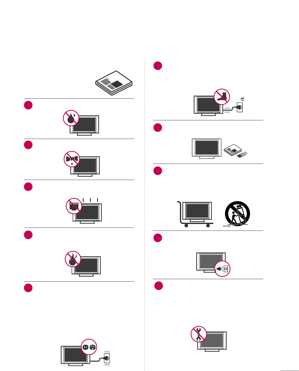
Do not use this apparatus near water.
Clean only with a dry cloth.
Do not block any ventilation openings. Install in
accordance with the manufacturer’s instructions.
Do not install near any heat sources such as
radiators, heat registers, stoves, or other apparatus
(including amplifiers)that produce heat.
Do not defeat the safety purpose of the polarized
or grounding-type plug. A polarized plug has
two blades with one wider than the other. A
grounding type plug has two blades and a third
grounding prong, The wide blade or the third
prong are provided for your safety. If the provided
plug does not fit into your outlet, consult an
electrician for replacement of the obsolete outlet.
Protect the power cord from being walked on
or pinched particularly at plugs, convenience
receptacles, and the point where they exit from
the apparatus.
Only use attachments/accessories specified by
the manufacturer.
Use only with the cart, stand, tripod, bracket,
or table specified by the manufacturer, or sold
with the apparatus. When a cart is used, use
caution when moving the cart/apparatus
combination to avoid injury from tip-over.
Unplug this apparatus during lighting storms or
when unused for long periods of time.
Refer all servicing to qualified service personnel.
Servicing is required when the apparatus has been
damaged in any way, such as power-supply cord or
plug is damaged, liquid has been spilled or objects
have fallen into the apparatus, the apparatus has
been exposed to rain or moisture, does not operate
normally, or has been dropped.
IMPORTANT SAFETY INSTRUCTIONS
1
2
3
4
5
7
8
6
9
10
4
Never touch this apparatus or antenna during a
thunder or lighting storm.
When mounting a TV on the wall, make sure not to
install the TV by the hanging power and signal
cables on the back of the TV.
Do not allow an impact shock or any objects to fall
into the product, and do not drop onto the screen
with something.
CAUTION concerning the Power Cord :
It is recommend that appliances be placed upon a
dedicated circuit; that is, a single outlet circuit which
powers only that appliance and has no additional
outlets or branch circuits. Check the specification
page of this owner's manual to be certain.
Do not connect too many appliances to the same
AC power outlet as this could result in fire or elec-
tric shock.
Do not overload wall outlets. Overloaded wall out-
lets, loose or damaged wall outlets, extension cords,
frayed power cords, or damaged or cracked wire
insulation are dangerous. Any of these conditions
could result in electric shock or fire. Periodically
examine the cord of your appliance, and if its
appearance indicates damage or deterioration,
unplug it, discontinue use of the appliance, and
have the cord replaced with an exact replacement
part by an authorized servicer. Protect the power
cord from physical or mechanical abuse, such as
being twisted, kinked, pinched, closed in a door, or
walked upon. Pay particular attention to plugs, wall
outlets, and the point where the cord exits the
appliance.
Do not make the TV with the power cord plugged
in. Do not use a damaged or loose power cord. Be
sure do grasp the plug when unplugging the power
cord. Do not pull on the power cord to unplug the
TV.
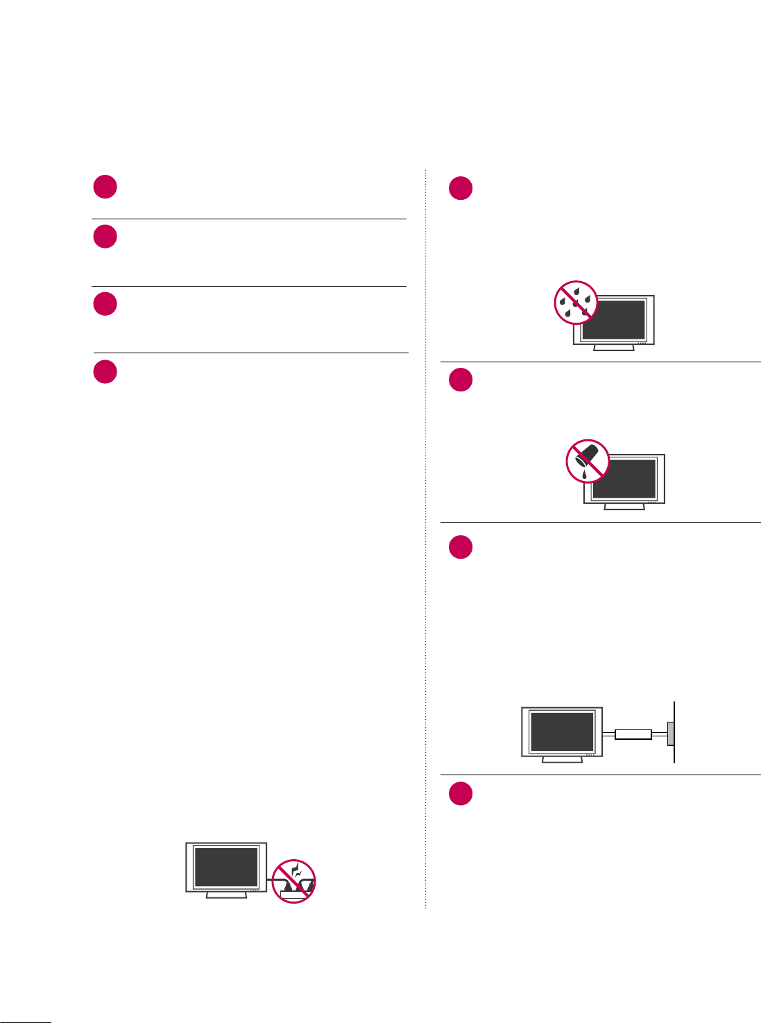
WARNING - To reduce the risk of fire or electrical
shock, do not expose this product to rain, moisture
or other liquids. Do not touch the TV with wet
hands. Do not install this product near flammable
objects such as gasoline or candles or expose the
TV to direct air conditioning.
Do not expose to dripping or splashing and do not
place objects filled with liquids, such as vases, cups,
etc. on or over the apparatus (e.g. on shelves above
the unit).
GROUNDING
Ensure that you connect the earth ground wire to
prevent possible electric shock. (i.e. a TV with a
three-prong grounded AC plug must be connected
to a three-prong grouned AC outlet) If grounding
methods are not possible, have a qualified electri-
cian install a separate circuit breaker.
Do not try to ground the unit by connecting it to
telephone wires, lightening rods, or gas pipes.
DISCONNECTING DEVICE FROM MAINS
Mains plug is the disconnecting device. The plug
must remain readily operable.
12
11
14
13
16
17
18
Power
Supply
Short-circuit
Breaker
15
5
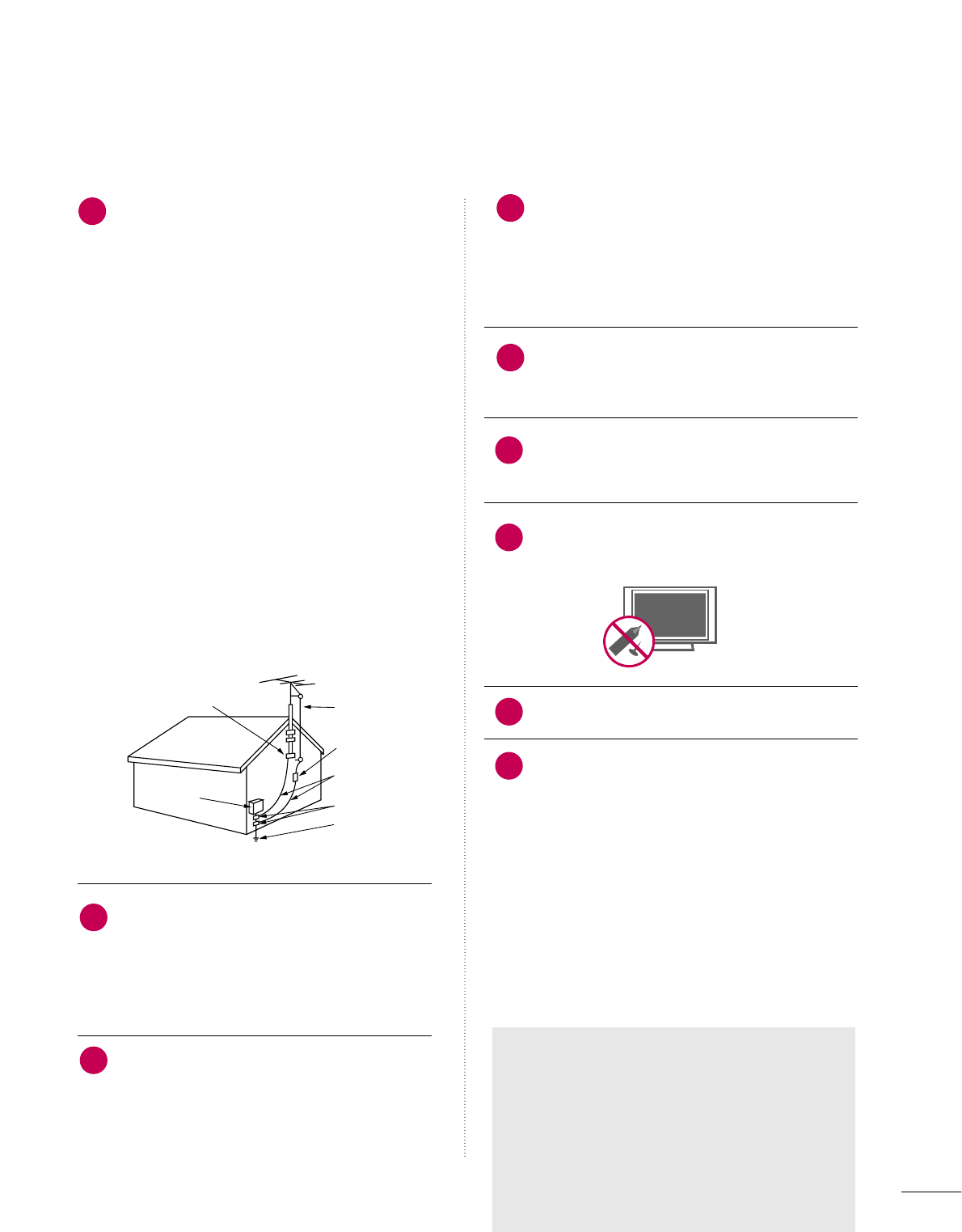
ANTENNAS
Outdoor antenna grounding
If an outdoor antenna is installed, follow the precau-
tions below. An outdoor antenna system should not
be located in the vicinity of overhead power lines or
other electric light or power circuits, or where it can
come in contact with such power lines or circuits as
death or serious injury can occur.
Be sure the antenna system is grounded so as to pro-
vide some protection against voltage surges and
built-up static charges.
Section 810 of the National Electrical Code (NEC) in
the U.S.A. provides information with respect to prop-
er grounding of the mast and supporting structure,
grounding of the lead-in wire to an antenna dis-
charge unit, size of grounding conductors, location of
antenna discharge unit, connection to grounding
electrodes and requirements for the grounding elec-
trode.
Antenna grounding according to the
National Electrical Code, ANSI/NFPA 70
Cleaning
When cleaning, unplug the power cord and scrub
gently with a soft cloth to prevent scratching. Do not
spray water or other liquids directly on the TV as
electric shock may occur. Do not clean with chemi-
cals such as alcohol, thinners or benzene.
Moving
Make sure the product is turned off, unplugged
and all cables have been removed. It may take 2 or
more people to carry larger TVs. Do not press
against or put stress on the front panel of the TV.
Ventilation
Install your TV where there is proper ventilation. Do
not install in a confined space such as a bookcase.
Do not cover the product with cloth or other mate-
rials (e.g.) plastic while plugged in. Do not install in
excessively dusty places.
Take care not to touch the ventilation openings.
When watching the TV for a long period, the venti-
lation openings may become hot.
If you smell smoke or other odors coming from the
TV or hear strange sounds, unplug the power cord
contact an authorized service center.
Do not press strongly upon the panel with a hand or
sharp object such as nail, pencil or pen, or make a
scratch on it.
Keep the product away from direct sunlight.
For LCD TV
If the TV feels cold to the touch, there may be
a small “flicker” when it is turned on. This is
normal, there is nothing wrong with TV.
Some minute dot defects may be visible on the
screen, appearing as tiny red, green, or blue
spots. However, they have no adverse effect on
the monitor's performance.
Avoid touching the LCD screen or holding your
finger(s) against it for long periods of time.
Doing so may produce some temporary dis-
tortion effects on the screen.
21
19
Antenna Lead in Wire
Antenna Discharge Unit
(NEC Section 810-20)
Grounding Conductor
(NEC Section 810-21)
Ground Clamps
Power Service Grounding
Electrode System (NEC
Art 250, Part H)
Ground Clamp
Electric Service
Equipment
NEC: National Electrical Code
22
23
24
25
20
ON DISPOSAL
(Only Hg lamp used LCD TV)
The fluorescent lamp used in this product contains
a small amount of mercury. Do not dispose of
this product with general household waste.
Disposal of this product must be carried out in
accordance to the regulations of your local authority.
26
27

6
CONTENTS
WARNING / CAUTION
. . . . . . . . . . . . . . . . . . . . . . . . . . . . 2
SAFETY INSTRUCTIONS
. . . . . . . . . . . . . . . . . . . . . . . . . . 3
FEATURES OF THIS TV
. . . . . . . . . . . . . . . . . . . . . . . . . . . . . 8
PREPARATION
Accessories . . . . . . . . . . . . . . . . . . . . . . . . . . . . . . . . . . . . . . . . . . . . . . . . . . . . . . 9
Front Panel Information . . . . . . . . . . . . . . . . . . . . . . . . . . . . . . . . . . . 10
Back Panel Information . . . . . . . . . . . . . . . . . . . . . . . . . . . . . . . . . . . . 12
Stand Instuction . . . . . . . . . . . . . . . . . . . . . . . . . . . . . . . . . . . . . . . . . . . . . . 15
Cable Management . . . . . . . . . . . . . . . . . . . . . . . . . . . . . . . . . . . . . . . . . 17
Desktop Pedestal Installation . . . . . . . . . . . . . . . . . . . . . . . . . . . 19
Swivel Stand . . . . . . . . . . . . . . . . . . . . . . . . . . . . . . . . . . . . . . . . . . . . . . . . . . . . 19
Attaching the TV to a desk . . . . . . . . . . . . . . . . . . . . . . . . . . . . . . 20
VESA Wall Mounting . . . . . . . . . . . . . . . . . . . . . . . . . . . . . . . . . . . . . . . . 21
Securing the TV to the wall to prevent falling
When the TV is used on a stand
. . . . . . . . . . . . . . . . . . . . . . . . . . 23
Antenna or Cable Connection . . . . . . . . . . . . . . . . . . . . . . . . . . 24
MPI Card Slot / PPV Card Installation . . . . . . . . . . . . . . 25
EXTERNAL EQUIPMENT SETUP
HD Receiver Setup . . . . . . . . . . . . . . . . . . . . . . . . . . . . . . . . . . . . . . . . . . 26
DVD Setup . . . . . . . . . . . . . . . . . . . . . . . . . . . . . . . . . . . . . . . . . . . . . . . . . . . . . 29
VCR Setup . . . . . . . . . . . . . . . . . . . . . . . . . . . . . . . . . . . . . . . . . . . . . . . . . . . . . 30
Other A/V Source Setup . . . . . . . . . . . . . . . . . . . . . . . . . . . . . . . . . 31
Audio Out Connection . . . . . . . . . . . . . . . . . . . . . . . . . . . . . . . . . . . . 31
PC Setup . . . . . . . . . . . . . . . . . . . . . . . . . . . . . . . . . . . . . . . . . . . . . . . . . . . . . . . . 32
WATCHING TV / CHANNEL CONTROL
Remote Control Functions . . . . . . . . . . . . . . . . . . . . . . . . . . . . . . . 38
Turning On TV . . . . . . . . . . . . . . . . . . . . . . . . . . . . . . . . . . . . . . . . . . . . . . . . 40
Channel Selection . . . . . . . . . . . . . . . . . . . . . . . . . . . . . . . . . . . . . . . . . . . 40
Volume Adjustment . . . . . . . . . . . . . . . . . . . . . . . . . . . . . . . . . . . . . . . . . 40
On-Screen Menus Selection . . . . . . . . . . . . . . . . . . . . . . . . . . . . . 41
Channel Setup
- Auto Scan (Auto Tuning) . . . . . . . . . . . . . . . . . . . . . . . . . . . 42
- Add / Delete Channel (Manual Tuning) . . . . . . 43
- Channel Editing . . . . . . . . . . . . . . . . . . . . . . . . . . . . . . . . . . . . . . . . 44
Channel Label . . . . . . . . . . . . . . . . . . . . . . . . . . . . . . . . . . . . . . . . . . . . . . . . . 44
Input List . . . . . . . . . . . . . . . . . . . . . . . . . . . . . . . . . . . . . . . . . . . . . . . . . . . . . . . . 45
Example Electronic Program Guide . . . . . . . . . . . . . . . . . . . 44
USB
Entry Modes . . . . . . . . . . . . . . . . . . . . . . . . . . . . . . . . . . . . . . . . . . . . . . . . . . . 47
Photo List . . . . . . . . . . . . . . . . . . . . . . . . . . . . . . . . . . . . . . . . . . . . . . . . . . . . . . . 49
Music List . . . . . . . . . . . . . . . . . . . . . . . . . . . . . . . . . . . . . . . . . . . . . . . . . . . . . . . 53
Extra contents . . . . . . . . . . . . . . . . . . . . . . . . . . . . . . . . . . . . . . . . . . . . . . . . . 55
PICTURE CONTROL
PIP (Picture-In-Picture) . . . . . . . . . . . . . . . . . . . . . . . . . . . . . . . . . . . . 56
Picture Size (Aspect Ratio) Control . . . . . . . . . . . . . . . . . . 58
Preset Picture Settings
- Picture Mode - Preset . . . . . . . . . . . . . . . . . . . . . . . . . . . . . . . 61
Manual Picture Adjustment
- Picture Mode - User Mode . . . . . . . . . . . . . . . . . . . . . . . . 62
Picture Improvement Technology . . . . . . . . . . . . . . . . . . . . . 63
Picture Reset . . . . . . . . . . . . . . . . . . . . . . . . . . . . . . . . . . . . . . . . . . . . . . . . . 65
Demo mode . . . . . . . . . . . . . . . . . . . . . . . . . . . . . . . . . . . . . . . . . . . . . . . . . . . . 66
SOUND & LANGUAGE CONTROL
Auto Volume Leveler (Auto Volume) . . . . . . . . . . . . . . . . . 67
Preset Sound Settings (Sound Mode) . . . . . . . . . . . . . . 68
Sound Setting Adjustment - User Mode . . . . . . . . . . . 69
- SRS TruSurround XT . . . . . . . . . . . . . . . . . . . . . . . . . . . . . . . . . 70
- Infinite Sound . . . . . . . . . . . . . . . . . . . . . . . . . . . . . . . . . . . . . . . . . . . 70
Clear Voice ll . . . . . . . . . . . . . . . . . . . . . . . . . . . . . . . . . . . . . . . . . . . . . . . . . . . 71
Balance . . . . . . . . . . . . . . . . . . . . . . . . . . . . . . . . . . . . . . . . . . . . . . . . . . . . . . . . . . 72
TV Speakers On/Off Setup . . . . . . . . . . . . . . . . . . . . . . . . . . . . . . 73
Audio Reset . . . . . . . . . . . . . . . . . . . . . . . . . . . . . . . . . . . . . . . . . . . . . . . . . . . 74
Stereo/SAP Broadcast Setup . . . . . . . . . . . . . . . . . . . . . . . . . . . 75
Audio Language . . . . . . . . . . . . . . . . . . . . . . . . . . . . . . . . . . . . . . . . . . . . . . 76
On-Screen Menus Language Selection . . . . . . . . . . . . . . 77
Caption Mode
- Analog Broadcasting System Captions . . . . . . . 78
- Digital Broadcasting System Captions . . . . . . . . 79
- Caption Option . . . . . . . . . . . . . . . . . . . . . . . . . . . . . . . . . . . . . . . 80

7
TIME SETTING
Clock Setting
- Auto Clock Setup . . . . . . . . . . . . . . . . . . . . . . . . . . . . . . . . . . . . . 81
- Manual Clock Setup . . . . . . . . . . . . . . . . . . . . . . . . . . . . . . . . . 82
Auto On/Off Time Setting . . . . . . . . . . . . . . . . . . . . . . . . . . . . . . 83
Sleep Timer Setting . . . . . . . . . . . . . . . . . . . . . . . . . . . . . . . . . . . . . . . . . 84
PARENTAL CONTROL / RATINGS
Set Password & Lock System . . . . . . . . . . . . . . . . . . . . . . . . . . . 86
Channel Blocking . . . . . . . . . . . . . . . . . . . . . . . . . . . . . . . . . . . . . . . . . . . . 88
Movie & TV Rating . . . . . . . . . . . . . . . . . . . . . . . . . . . . . . . . . . . . . . . . . 89
Downloadable Rating . . . . . . . . . . . . . . . . . . . . . . . . . . . . . . . . . . . . . . 92
External Input Blocking . . . . . . . . . . . . . . . . . . . . . . . . . . . . . . . . . . . . 93
COMMERCIAL MODE SETUP
Interactive TV Setup . . . . . . . . . . . . . . . . . . . . . . . . . . . . . . . . . . . . . . . . 94
Installer Overview . . . . . . . . . . . . . . . . . . . . . . . . . . . . . . . . . . . . . . . . . . . . 95
Interactive TV Overview . . . . . . . . . . . . . . . . . . . . . . . . . . . . . . . . . . . 96
Commercial Mode Setup for Master TV . . . . . . . . . . . . 97
Master TV Profile Setup Learning/Teaching with
USB Memory Card . . . . . . . . . . . . . . . . . . . . . . . . . . . . . . . . . . . . . . . . . . 98
TLL-1100A Cloning Connections/Learning Setup
. . . . . . . . . . . . . . . . . . . . . . . . . . . . . . . . . . . . . . . . . . . . . . . . . . . . . . . . . . . . . . . . . . . . 10 0
LT2002 Cloning Connections/Learning Setup . 101
LT2002 Cloning Learning Setup . . . . . . . . . . . . . . . . . . . . . 102
Cloning Connections/Teaching Setup . . . . . . . . . . . . . 103
Installer Menu . . . . . . . . . . . . . . . . . . . . . . . . . . . . . . . . . . . . . . . . . . . . . . . 10 4
Reference: Detailed Instructions For Making A
Master TV . . . . . . . . . . . . . . . . . . . . . . . . . . . . . . . . . . . . . . . . . . . . . . . . . . . . . 110
Reference: Procedures for adding Channel Label
Icons/Custom Channel Labels (2-5-4 + MENU
Mode) . . . . . . . . . . . . . . . . . . . . . . . . . . . . . . . . . . . . . . . . . . . . . . . . . . . . . . . . . . . 111
Reference: Clonable Menu Features . . . . . . . . . . . . . . . . . 112
Reference: Power Saving Setup . . . . . . . . . . . . . . . . . . . . . . . . 113
TV Camport Auto Sense Operation . . . . . . . . . . . . . . . . 115
FTG Operation Setup . . . . . . . . . . . . . . . . . . . . . . . . . . . . . . . . . . . .116
FTG Channel Map Overview . . . . . . . . . . . . . . . . . . . . . . . . . . .117
FTG Installer Menu Overview . . . . . . . . . . . . . . . . . . . . . . . . . .118
FTG Operation Troubleshooting . . . . . . . . . . . . . . . . . . . . .119
TV Aux Input Configuration . . . . . . . . . . . . . . . . . . . . . . . . . . . . .119
B-LAN Setup and Overview . . . . . . . . . . . . . . . . . . . . . . . . . . .120
APPENDIX
Troubleshooting . . . . . . . . . . . . . . . . . . . . . . . . . . . . . . . . . . . . . . . . . . . . . 121
Reference: LT2002 Cloning Procedure
Troubleshooting . . . . . . . . . . . . . . . . . . . . . . . . . . . . . . . . . . . . . . . . . . . . 122
Troubleshooting Flow Chart . . . . . . . . . . . . . . . . . . . . . . . . . . . 124
Commercial Mode Check . . . . . . . . . . . . . . . . . . . . . . . . . . . . . . . 125
Reference: RJP model list and input hierarchy . . 125
Glossary of Terms . . . . . . . . . . . . . . . . . . . . . . . . . . . . . . . . . . . . . . . . . . 126
Maintenance . . . . . . . . . . . . . . . . . . . . . . . . . . . . . . . . . . . . . . . . . . . . . . . . . 127
Product Specifications . . . . . . . . . . . . . . . . . . . . . . . . . . . . . . . . . . . 128
Programming the Remote Control . . . . . . . . . . . . . . . . . . . 130
IR Codes . . . . . . . . . . . . . . . . . . . . . . . . . . . . . . . . . . . . . . . . . . . . . . . . . . . . . . . 133
Open Source License . . . . . . . . . . . . . . . . . . . . . . . . . . . . . . . . . . . . . 135

8
FEATURES OF THIS TV
■
When a fixed image (e.g. logos, screen menus, video game, and computer display) is displayed on the TV
for an extended period, it can become permanently imprinted on the screen. This phenomenon is known
as “image burn” or “burn-in.” Image burn is not covered under the manufacturer’s warranty.
■
In order to prevent image burn, avoid displaying a fixed image on your TV screen for a prolonged period
(2 or more hours for LCD, 1 or more hours for Plasma).
■
Image burn can also occur on the letterboxed
areas of your TV if you use the 4:3 aspect
ratio setting for an extended period.
IMPORTANT INFORMATION TO PREVENT “IMAGE BURN
/ BURN-IN” ON YOUR TV SCREEN
Automatically enhances and amplifies the sound of
human voice frequency range to help keep dialogue
audible when background noise swells.
LG TV include a unique invisible speaker system,
tuned by renowned audio expert, Mr. Mark Levinson.
Speakers are embedded in strategic spots behind the
front cabinet and use minute vibrations to turn the
entire front bezel into the speaker system. The result
is a clean, polished look, and enhanced audio by
increasing the “sweet spot”, giving a wider and richer
sound field.
HDMI, the HDMI logo and High-Definition
Multimedia Interface are trademarks or registered
trademarks of HDMI Licensing LLC."
is a trademark of SRS Labs, Inc.
TruSurround XT technology is incorporated under
license from SRS Labs, Inc.
Manufactured under license from Dolby Laboratories.
“
Dolby
“and the double-D symbol are trademarks of
Dolby Laboratories.
High-definition television. High-resolution digital
television broadcast and playback system composed
of roughly a million or more pixels, 16:9 aspect-ratio
screens, and AC3 digital audio. A subset of digital
television, HDTV formats include 1080i and 720p
resolutions.
Unlike other sensors which can only sense brightness
of ambient light, LG’s “Intelligent Sensor” uses 4,096
sensing steps to evaluate its surroundings. Using a
sophisticated algorithm, the LG processes picture
quality elements including brightness, contrast, color,
sharpness and white balance. The result is a picture
optimized for it’s surroundings, more pleasing to
watch and which can also save up to 50% in power
consumption.
Matches the original frame rate of the film for a more
film-like experience
View videos and photos and listen to music on your
TV through USB 2.0 (‘videos’ dependent on model).
■This feature is not available for all models.
PREPARATION
9
PREPERATION
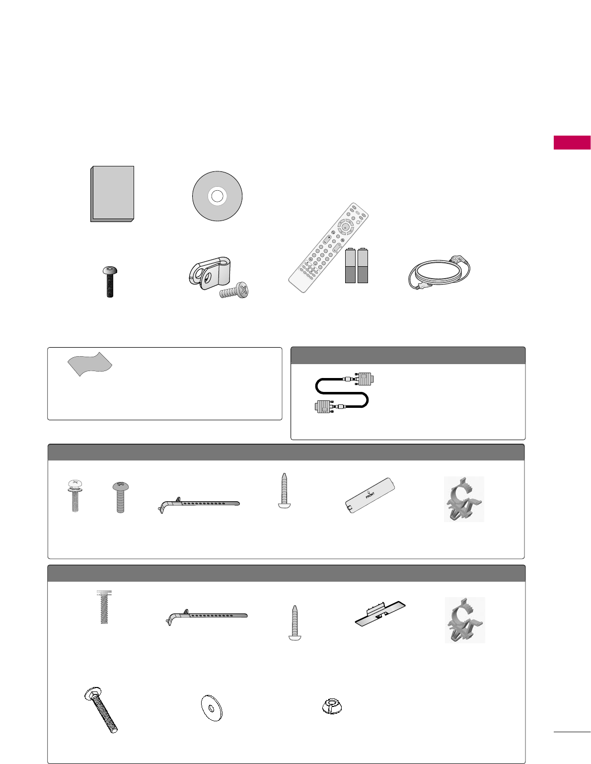
ACCESSORIES
Ensure that the following accessories are included with your TV. If an accessory is missing, please contact the
dealer where you purchased the TV.
The accessories included may differ from the images below.
Owner’s Manual
Power Cord
CD Manual
Protective Bracket and
Screw for Power Cord
(Refer to P.17, P.18)
Cable Holder
(Refer to P.17)
Cable Holder
(Refer to P.18)
* Wipe spots on the exterior only with the pol-
ishing cloth.
* Do not wipe roughly when removing stains.
Excessive pressure may cause scratches or
discoloration.
Polishing Cloth
(Not included with all
models.)
Option Extras
D-sub 15 pin Cable
When using the VGA (D-sub 15 pin
cable) PC connection, the user
must use shielded signal interface
cables with ferrite cores to maintain
standards compliance.
x 2
Torx plus
Star head screw
(Refer to P.15)
Screw for
stand fixing
(Refer to P.20)
Screw for stand fixing
(Refer to P.20)
Screws for stand fixing
(Refer to P.20)
Washers for stand fixing
(Refer to P.20)
Nuts for stand fixing
(Refer to P.20)
Screws for stand
assembly
(Refer to P.15)
Screws for stand assembly
(Refer to P.16)
x 4
x 8
x 2 x 2
(M4 x 20)
x 4
1.5V 1.5V
Remote Control,
Batteries
MUTE
RETURN
CC
TV
POWER
GUIDE
PORTAL
ENTER
VOL CH
123
456
78
0
9
FLASHBK
VCR
DVD
INPUT
MENU
INFO
i
STB
P
A
G
E
PIP SAP
PIP CH- PIP CH+
PIP SWAP
PIP INPUT
ALPHA/NUM
REMOVE
RATIO
TIMER
ABC DEF
GHI
WXYZ
TUV
PQRS
MNO
JKL
&@
.:/,
Protection Cover
(Refer to P.15)
Protection Cover
(Refer to P.16)
Plug in type Holder
(Refer to P.17)
Plug in type Holder
(Refer to P.18)
For 32/37/42LG710H
For 32/37/42/47/55LD650H
(For 32LG710H)
(For 32/37/42LD650H)
(For 32/37/42LD650H)
(For 32/37/42LD650H) (For 32/37/42LD650H) (For 32/37/42LD650H)
x 2
PREPARATION
10
PREPARATIONPREPARATION
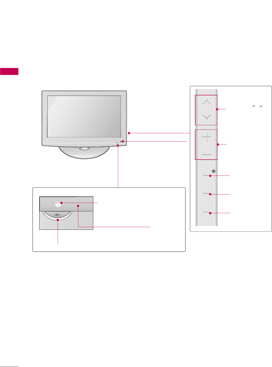
FRONT PANEL INFORMATION
■
Image shown may differ from your TV.
POWER Button
Power/Standby Indicator
Illuminates red in standby mode.
Illuminates blue when the set is
switched on.
CH
VOL
MENU
INPUT
ENTER
VOLUME (+, -)
Buttons
ENTER Button
MENU Button
INPUT Button
Remote Control Sensor
CHANNEL( , )
Buttons
Intelligent Sensor
Adjusts picture according to
the surrounding conditions.
32/37/42LG710H
PREPARATION
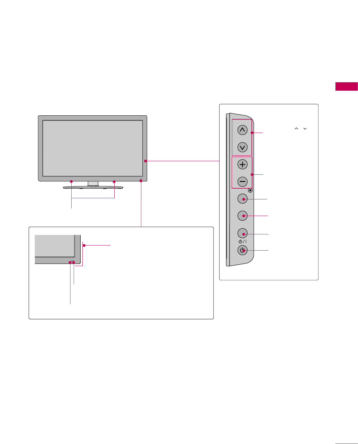
11
Intelligent Sensor
Adjust picture according to the surrounding conditions
Power/Standby Indicator
Illuminates red in standby mode.
Illuminates blue when the set is
switched on.
Remote Control Sensor
SPEAKER
CH
VOL
ENTER
INPUT
MENU
VOLUME (+, -)
Buttons
ENTER Button
MENU Button
INPUT Button
POWER Button
CHANNEL( , )
Buttons
32/37/42/47/55LD650H
PREPARATION
12
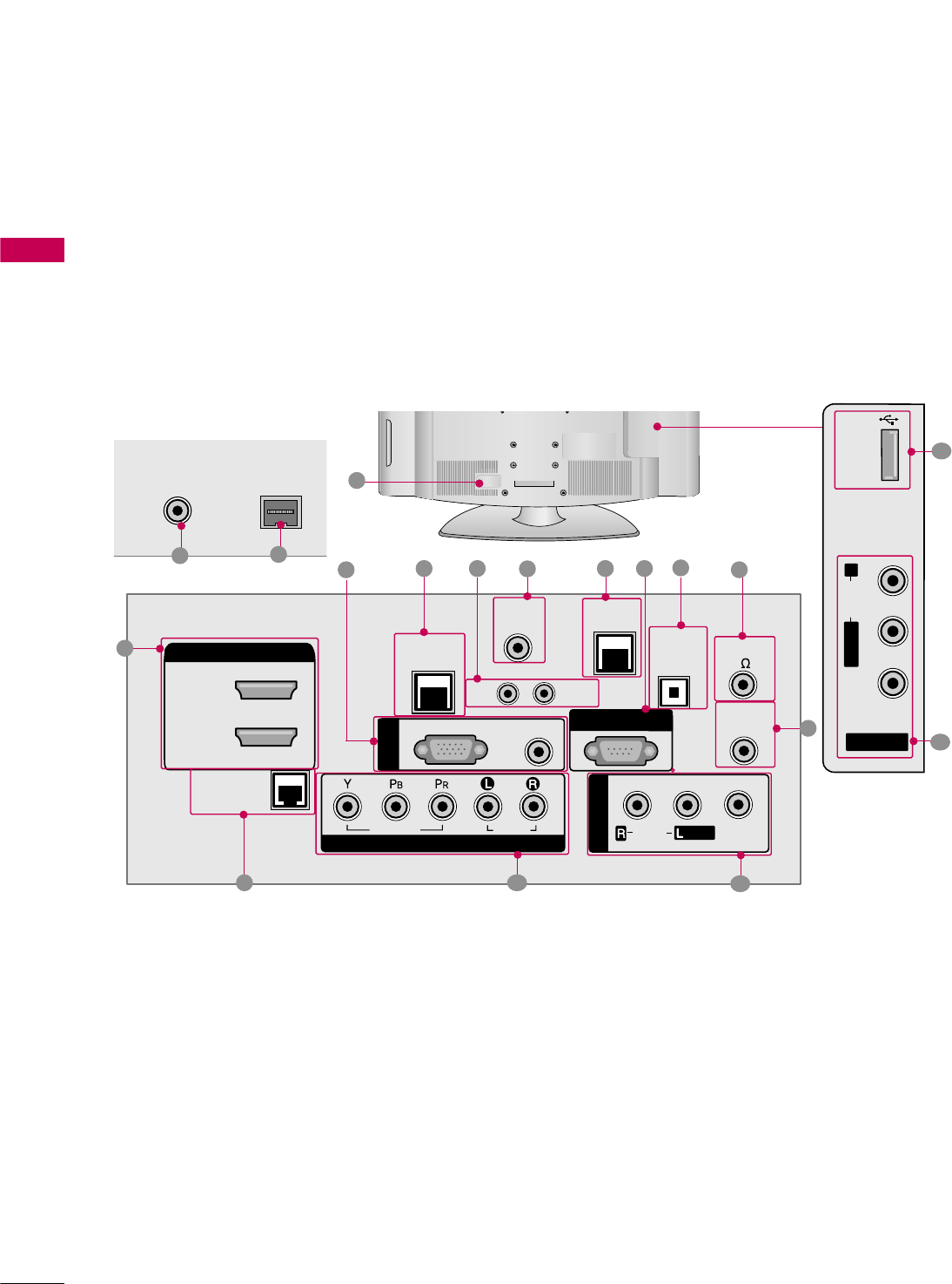
PREPARATION
■
Image shown may differ from your TV.
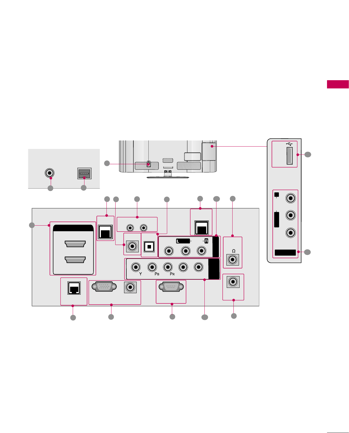
BACK PANEL INFORMATION
AV IN 2
L/MONO
R
AUDIO
VIDEO
USB IN
REMOTE
CONTROL OUT
OPTICAL
DIGITAL
AUDIO OUT
AV IN 1
AUDIO
VIDEO
MONO
/
UPDATE
RESET
LAN
(SERVICE ONLY)
COMPONENT IN
VIDEO
AUDIO
HDMI/DVI IN
2
1(DVI)
RJP
INTERFACE
SPEAKER OUT
8
RGB(PC)
AUDIO
(RGB/DVI)
RGB IN
RS-232C IN
(SERVICE ONLY)
TV-LINK
CFG
GAME
CONTROL
10
38
ANTENNA IN
ANTENNA IN
M.P.I.
M.P.I.
7
1
492
13 12 11
17
14
16
15
11
6
5
32/37/42LG710H
PREPARATION
13
7
ANTENNA INANTENNA IN M.P.I.M.P.I.
14 15
32/37/42/47/55LD650H
REMOTE
CONTROL OUT
OPTICAL
DIGITAL
UPDATE
RESET
LAN
HDMI/DVI IN
2
1
RJP
INTERFACE
SPEAKER
OUT
8
RGB IN (PC)
AUDIO IN
(RGB/DVI)
TV-LINK
CFG
GAME
CONTROL
RS-232C IN
(SERVICE ONLY)
AUDIO OUT
AV IN 1
AUDIO
VIDEO
MONO
/
CONPONENT
IN
LR
AC IN
1
13
34
210
9
6
5811
12
AV IN 2
L/MONO
R
AUDIO
VIDEO
USB IN
17
11
16

PREPARATION
14
PREPARATION
HDMI/DVI IN
Digital Connection. Supports HD video and Digital
audio.
Accepts DVI video using an adapter or HDMI to DVI
cable (not included)
RGB (PC)
Analog PC Connection. Uses a D-sub 15 pin cable
(VGA cable).
AUDIO (RGB/DVI)
1/8” headphone jack for analog PC audio input.
LAN (SERVICE ONLY)
For connecting to a control network.
RESET
Performs a hardware reset.
UPDATE
Enables/disables software downloads and debug mode.
TV - LINK CFG
Computer input for programming Free To Guest ser-
vices.
GAME CONTROL
Input port for third party game Controllers.
RS-232C IN (SERVICE ONLY)
Used for software updates.
OPTICAL DIGITAL AUDIO OUT
Optical digital audio output for use with amps and
home theater systems.
Note: In standby mode, this port doesn’t work.
SPEAKER OUT 8Ω
For use with external speakers.
REMOTE CONTROL OUT
IR output for controlling an auxiliary device.
AV (Audio/Video) IN 1/2
Analog composite connection. Supports standard
definition video only (480i).
COMPONENT IN
Analog Connection. Supports HD.
Uses a red, green, and blue cable for video & a red
and white cable for audio.
RJP INTERFACE (REMOTE JACK PACK PORT)
Connect this to an LG remote jack pack system.
ANTENNA IN
Connect an antenna to receive over-the-air (OTA)
signals.
M.P. I.
Allows VOD/PPV devices or set-top boxes to control
the TV. (Except 47/55LD650H)
Power Cord Socket
AC power input.
Caution: Never attempt to operate the TV on DC
power.
USB IN
Used for viewing multimedia files.
1
2
3
4
5
6
7
9
8
10
11
12
13
14
15
17
16
PREPARATION
15
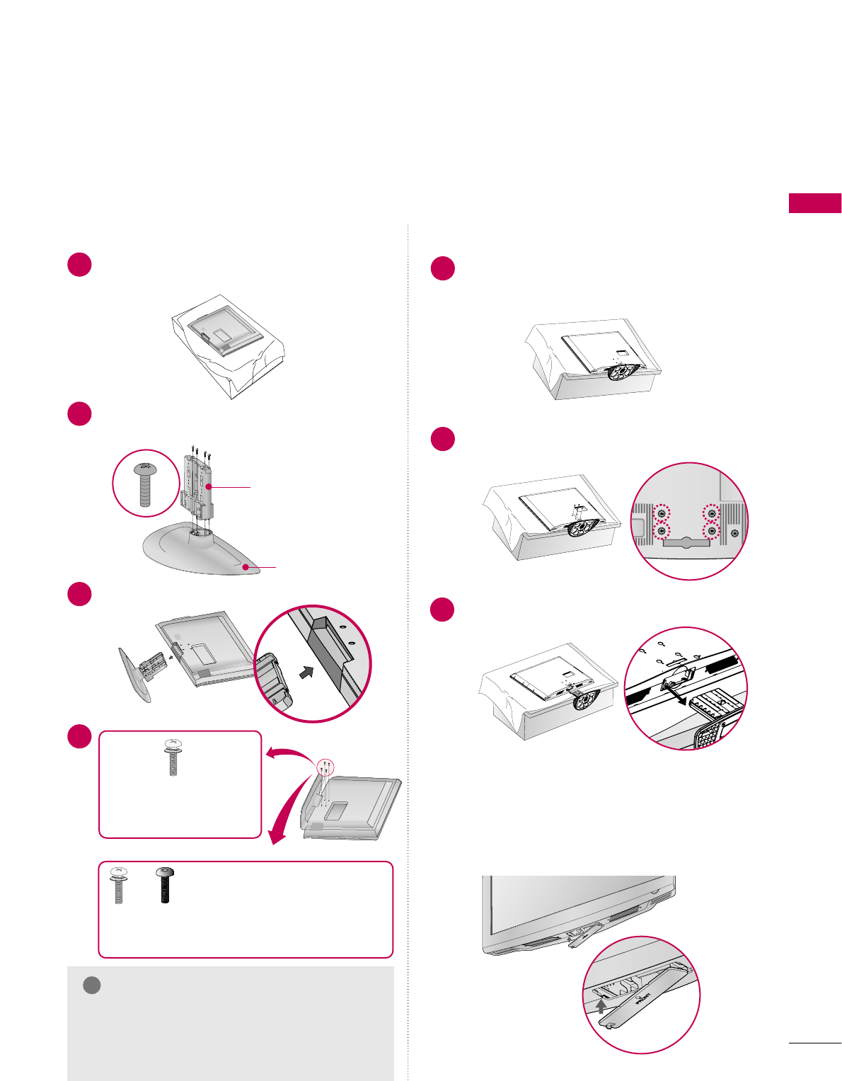
STAND INSTRUCTION
Carefully place the TV screen side down on a
cushioned surface to protect the screen from
damage.
Assemble the STAND BODY to the COVER
BASE with the included screws.
1
2
Insert the stand as shown.
3
STAND BODY
COVER BASE
■
Image shown may differ from your TV.
GGMake sure the screws in the stand are fully
tightened. (If not tightened fully, the product
could tilt forward and fall). But do not over
tighten, over-tightening can damage the threads
on the screws.
NOTE
!
DETACHMENT
Carefully place the TV screen side down on a
cushioned surface to protect the screen from
damage.
1
Remove the four screws that hold the base on.
2
Detach the stand from TV.
3
INSTALLATION
4
or
x 4
Tighten the stand with the
four screws (provided as parts
of the TV).
Tighten the two of these four screws
and the two Torx plus star head screws
(provided as parts of the TV) to secure the TV. Tighten
the two Torx plus star head screws with a star head dri-
ver bit (not provided as parts of the TV).
x 2 x 2
After removing the stand, install the included
protection cover over the hole for the stand.
Press the PROTECTION COVER into the TV
until you hear it click.
PROTECTION COVER
32/37/42LG710H
PREPARATION
16
PREPARATION
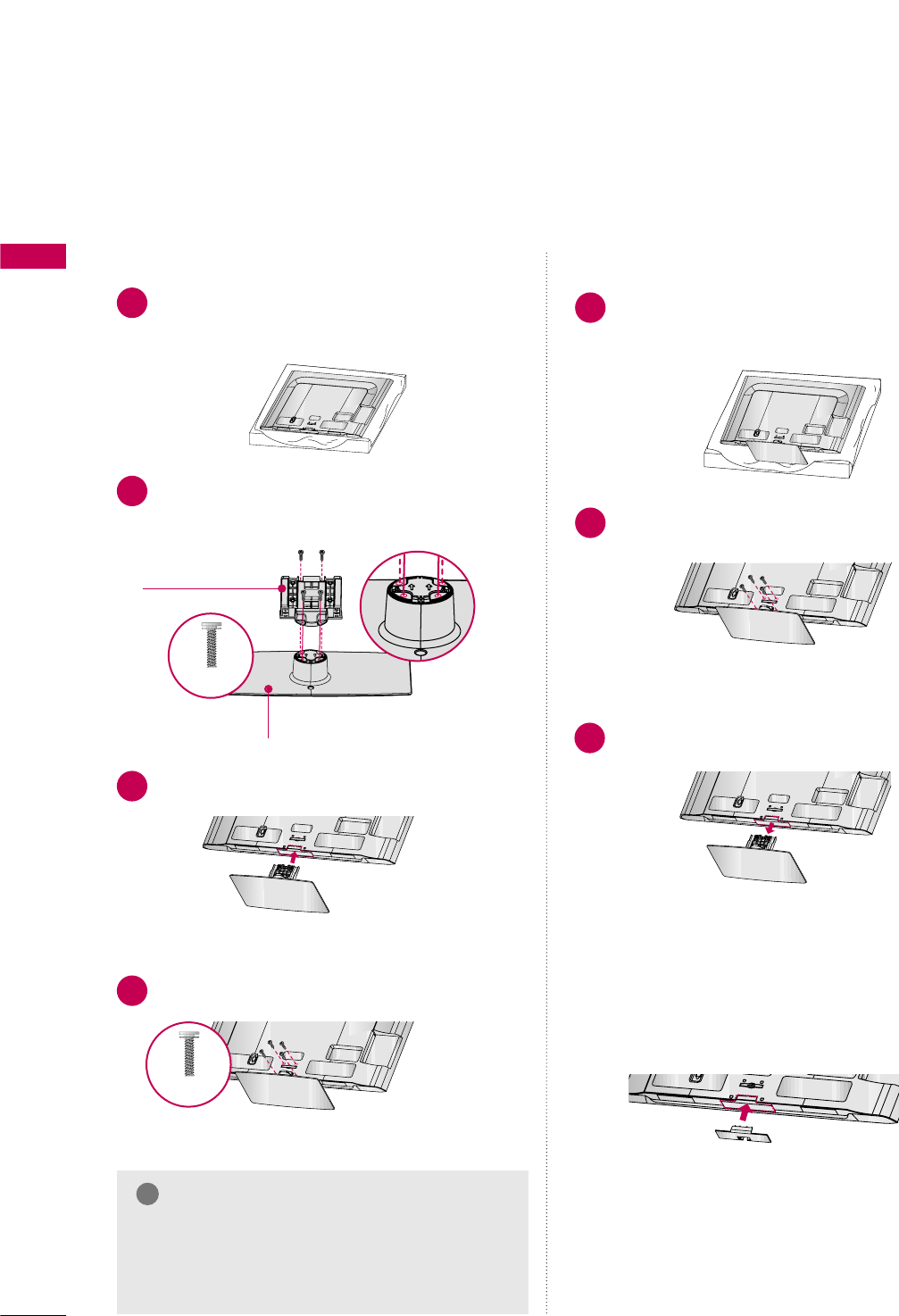
32/37/42/47/55LD650H
AC IN
CABLE MANAGEMENT
Carefully place the TV screen side down on a
cushioned surface to protect the screen from
damage.
Assemble the parts of the STAND BODY
with the STAND BASE of the TV.
1
2
Assemble the TV as shown.
3
AC IN
CABLE MANAGEMENT
Install the 4 screws into the holes shown.
AC IN
CABLE MANAGEMENT
STAND BODY
STAND BASE
GWhen assembling the desk type stand, make sure
the screws are fully tightened (If not tightened
fully, the TV can tilt forward after the protuct
installation). Do not over tighten.
NOTE
!
DETACHMENT
AC IN
CABLE MANAGEMEN
T
Carefully place the TV screen side down on a
cushioned surface to protect the screen from
damage.
1
Remove the screws that hold the stand on.
2
Detach the stand from TV.
3
AC IN
CABLE MANAGEMENT
INSTALLATION
4After removing the stand, install the included
protection cover over the hole for the stand.
Press the PROTECTION COVER into the TV
until you hear it click.
PROTECTION COVER
AC IN
CABLE MANAGEMENT
M4 x 20
M4 x 20
PREPARATION
17
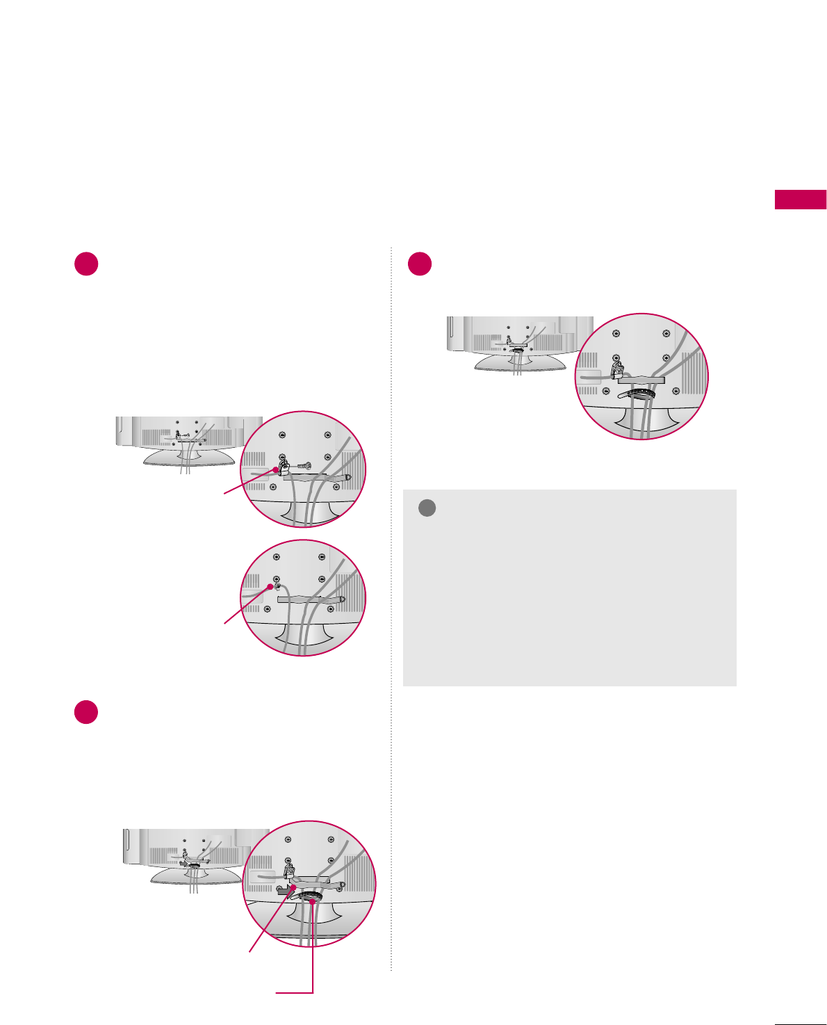
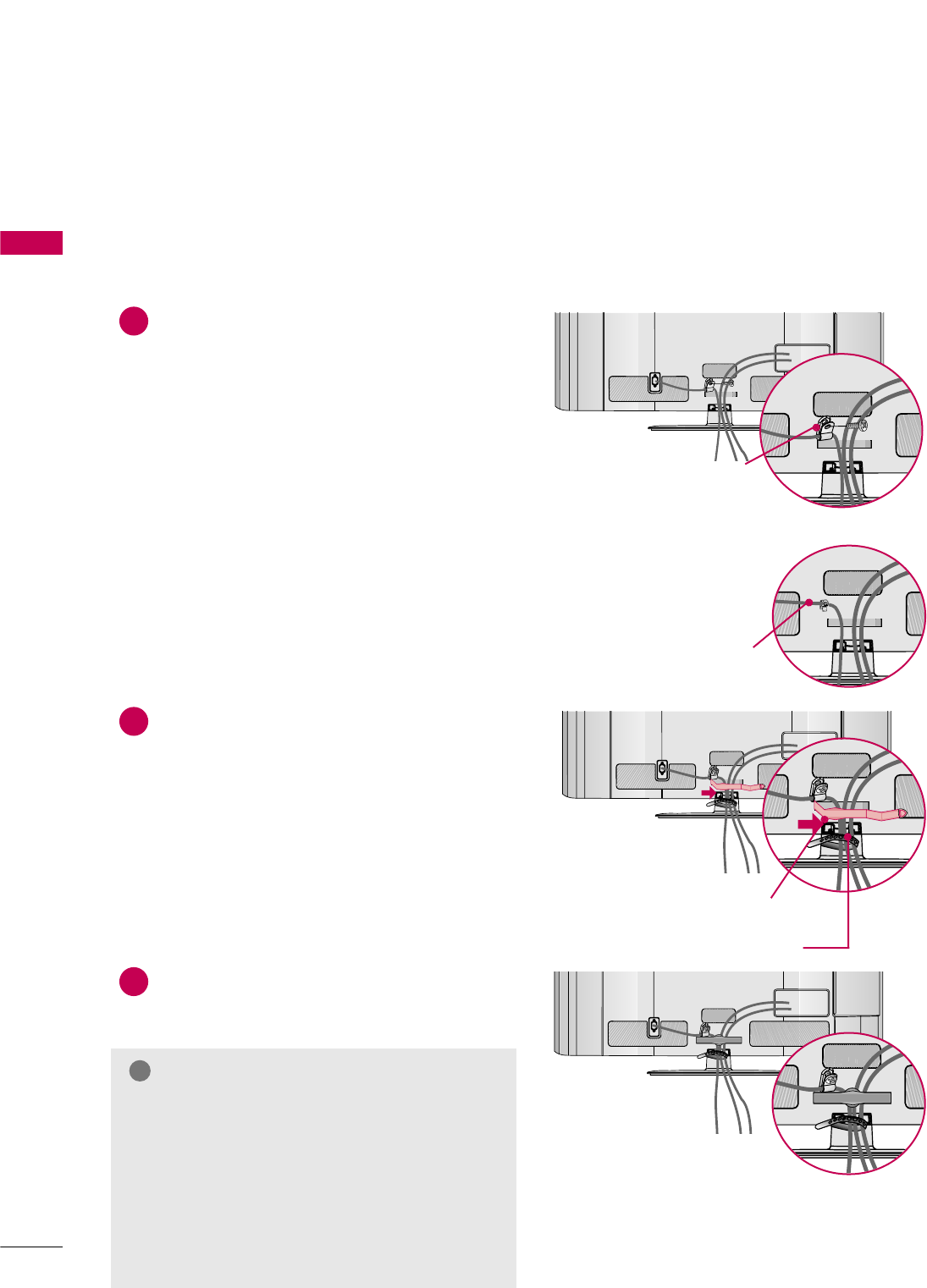
CABLE MANAGEMENT
■
Image shown may differ from your TV.
Connect the cables as needed after reading
the section titled EXTERNAL EQUIPMENT
SETUP.
To help prevent the power cable from being
removed by accident, secure the power cable
with the included PROTECTIVE BRACKET
/Screw. The 32LG710H uses a Plug in type
Holder instead of using a screw.
Install the CABLE MANAGEMENT CLIP as
shown.
If a CABLE HOLDER was included with your
TV, install it as shown.
1
2
Put the cables inside the CABLE MANAGEMENT
CLIP and snap it closed.
3
GDo not hold the CABLE MANAGEMENT CLIP
when moving the TV.
- If the TV is dropped, you may be injured or the
product may be broken.
GWith some TVs, the PLUG IN TYPE HOLDER
and the CABLE HOLDER are included. If these
holders are inserted into the hole provided on
back of the TV, they cannot be removed.
NOTE
!
CABLE MANAGEMENT CLIP
CABLE HOLDER
PROTECTIVE BRACKET/Screw
(This feature is not available for
all models.)
PLUG IN TYPE HOLDER
(For 32LG710H model)
Or
32/37/42LG710H
PREPARATION
18
PREPARATION
32/37/42/47/55LD650H
Connect the cables as necessary.
To connect additional equipment, see the
EXTERNAL EQUIPMENT SETUP section.
For 32/37/42LD650H: To help prevent the
power cable from being removed by acci-
dent, secure the power cable with the
included
P
ROTECTIVE BRACKET /SCREW.
The 32/37/42LD650H use a Plug in type
Holder instead of using a screw.
1
AC IN
Open the CABLE MANAGEMENT CLIP as
shown.
2
AC IN
Put the cables inside the CABLE MANAGE-
MENT CLIP and snap it closed.
3
AC IN
PROTECTIVE BRACKET/SCREW
(For 32/37/42LD650H model)
PLUG IN TYPE HOLDER
(For 32/37/42LD650H model)
Or
G
Do not hold the CABLE MANAGEMENT CLIP
when moving the TV.
- If the TV is dropped, you may be injured or the
product may be broken.
G
With some TVs, the PLUG IN TYPE HOLDER
and the CABLE HOLDER are included. If these
holders are inserted into the hole provided on
back of the TV, they cannot be removed.
NOTE
!
CABLE MANAGEMENT CLIP
CABLE HOLDER
(For 32/37/42LD650H model)
PREPARATION
19
PREPARATION
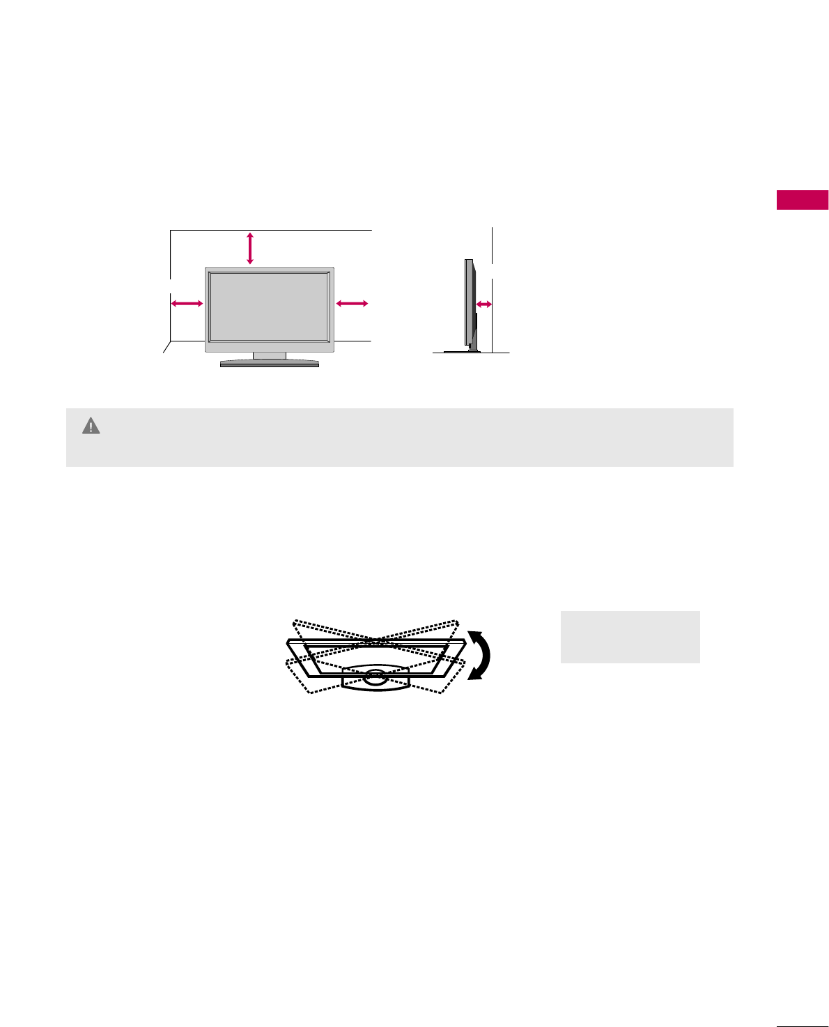
DESKTOP PEDESTAL INSTALLATION
For proper ventilation, allow a clearance of 4 inches on all four sides.
■
Image shown may differ from your TV.
4 inches
4 inches
4 inches
4 inches
SWIVEL STAND
The TV can be conveniently swivelled on its stand to the left or right to provide the optimum viewing angle.
GEnsure adequate ventilation by following the clearance recommendations.
GDo not mount near or above any type of heat source.
CAUTION
20° : 47/55LD650H
90° : Other Models
PREPARATION
20
PREPARATION
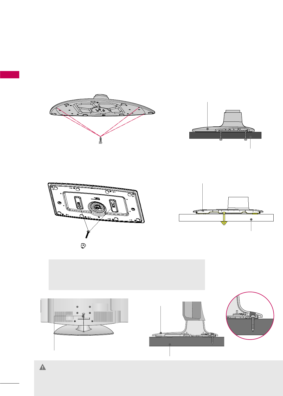
ATTACHING THE TV TO A DESK
The TV should be attached to a desk so it cannot be pulled in a forward/backward direction, potentially causing
injury or damaging the product.
G
To prevent TV from falling over, the TV should be securely attached to the floor/wall per installation
instructions. Tipping, shaking, or rocking the TV may cause injury.
WARNING
1-Screw
(provided as parts of the product)
Desk
Stand
4-Screws
(not provided as parts of the product)
G
Recommended screw size: M5 x L (
*L: Table depth + 8
~10 mm)
ex) Table depth: 15mm, Screw: M5 x 25
G
Do not over tighten.
Desk
Stand
32/37/42LD650H
2-Screws, 2-Washers, 2-Nuts
(provided as parts of the product)
Stand
Desk
32/37/42LG710H
PREPARATION
21
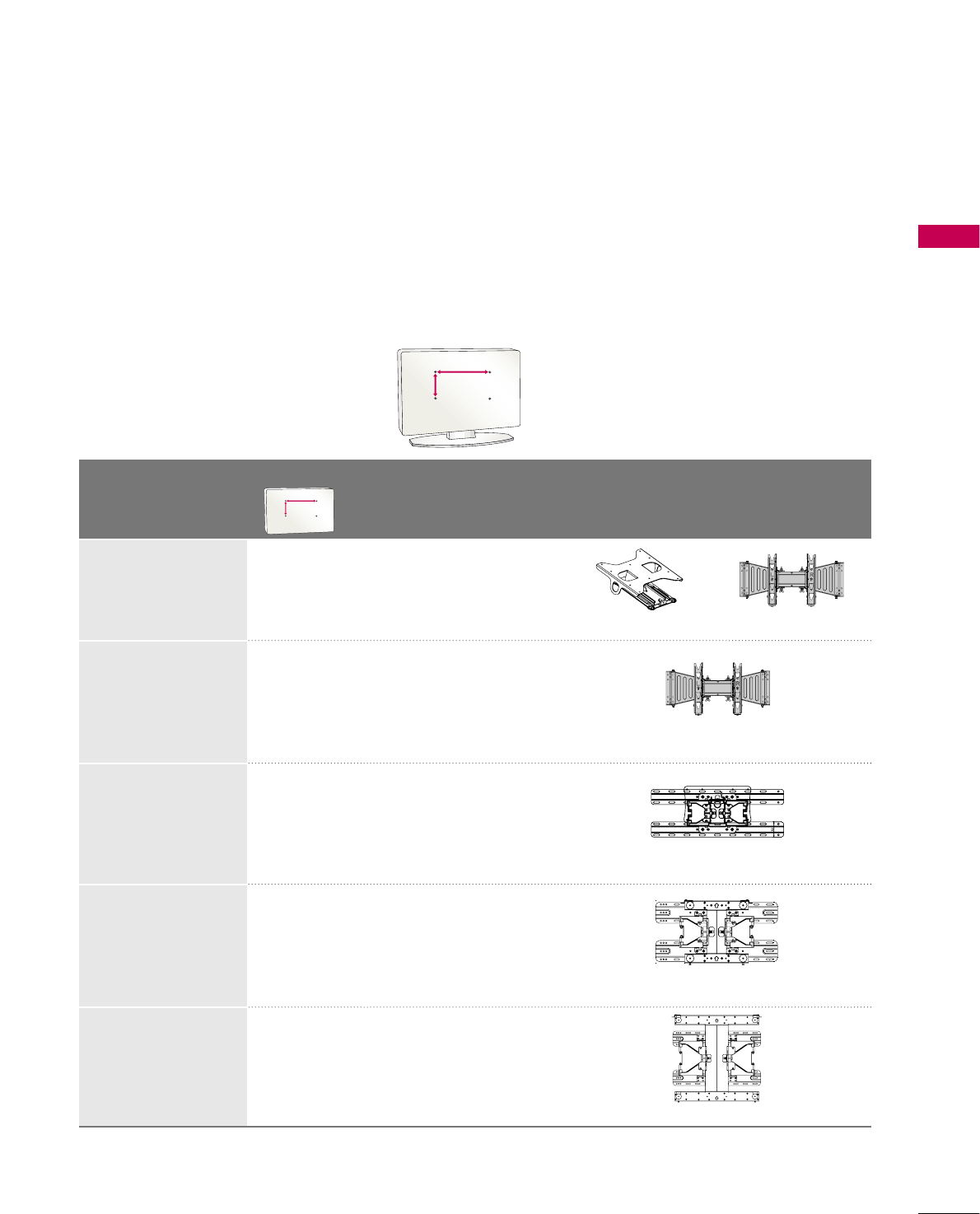
VESA WALL MOUNTING
Install your wall mount on a solid wall perpendicular to the floor. When attaching to other building materials, please
contact your nearest installer.
If installed on a ceiling or slanted wall, it may fall and result in severe personal injury.
We recommend that you use an LG brand wall mount when mounting the TV to a wall.
LG recommends that wall mounting be performed by a qualified professional installer.
AA
BB
Model
VESA (A *B)
Standard Screw Quantity Wall Mounting Bracket
(sold separately)
32LG710H
37LG710H,
42LG710H
32LD650H
37LD650H,
42LD650H,
47LD650H
55LD650H
200 * 10 0 M 4 4
200 * 10 0 M 4 4
200 * 200 M6 4
400 * 400 M6 4
200 * 200 M6 4
AA
BB
AW-47LG30M
LSW100B, LSW100BG
LSW200B, LSW200BG
LSW400B, LSW400BG
RW230 AW-47LG30M

PREPARATION
22
PREPARATION
G
Do not install your wall mount kit while the TV is plugged in. It may result in personal injury due to electric shock.
CAUTION
GScrew length needed depends on the wall mount
used. For further information, refer to the instruc-
tions included with the mount.
GStandard dimensions for wall mount kits are shown
in the table.
GWhen purchasing our wall mount kit, a detailed
installation manual and all parts necessary for
assembly are provided.
GDo not use screws longer then the standard dimen-
sion, as they may cause damage to the inside to
the TV.
GFor wall mounts that do not comply with the VESA
standard screw specifications, the length of the
screws may differ depending on their specifica-
tions.
GDo not use screws that do not comply with the
VESA standard screw specifications.
Do not tighten the screws too much. It may dam-
age the TV or allow the TV to a fall and cause per-
sonal injury. LG is not liable for these kinds of acci-
dents.
GLG is not liable for TV damage or personal injury
when a non-VESA or non specified wall mount is
used or the consumer fails to follow the TV installa-
tion instructions.
NOTE
!
GTo prevent injury, this apparatus must be securely attached to the wall in accordance with the installa-
tion instructions.
WARNING
PREPARATION
23
SECURING THE TV TO THE WALL TO PREVENT FALLING
WHEN THE TV IS USED ON A STAND
We recommend that you set up the TV close to a wall so it cannot fall over if pushed backwards.
Additionally, we recommend that the TV be attached to a wall so it cannot be pulled in a forward direction,
potentially causing injury or damaging the product.
Caution: Please make sure that children don’t climb on or hang from the TV.
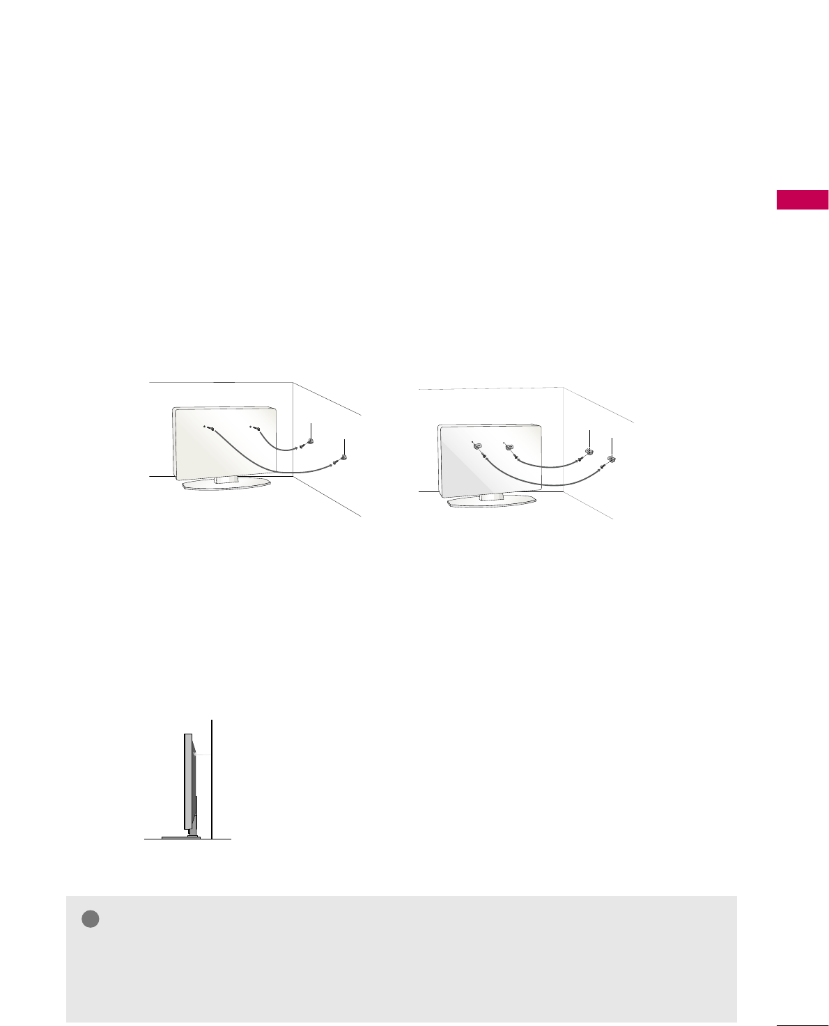
■Insert the eye-bolts (or TV brackets and bolts) to tighten the product to the wall as shown in the pic-
ture.
*If your product has the bolts in the eye-bolts position before inserting the eye-bolts, loosen the
bolts.
* Insert the eye-bolts or TV brackets/bolts and tighten them securely in the upper holes.
Secure the wall brackets with the bolts (sold separately) to the wall. Match the height of the bracket
that is mounted on the wall to the holes in the product.
Ensure the eye-bolts or brackets are tightened securely.
■Use a sturdy rope (sold separately) to tie the product. It is safer to
tie the rope so it becomes horizontal between the wall and the prod-
uct.
■
You should purchase necessary components to prevent the TV from tipping over (when not using a wall mount).
■
Image shown may differ from your TV.
GUse a platform or cabinet strong enough and large enough to support the size and weight of the TV.
GTo use the TV safely make sure that the height of the bracket on the wall and the one on the TV are the same.
NOTE
!
PREPARATION
24
PREPARATION
ANTENNA INANTENNA IN
PREPARATION
ANTENNA OR CABLE CONNECTION
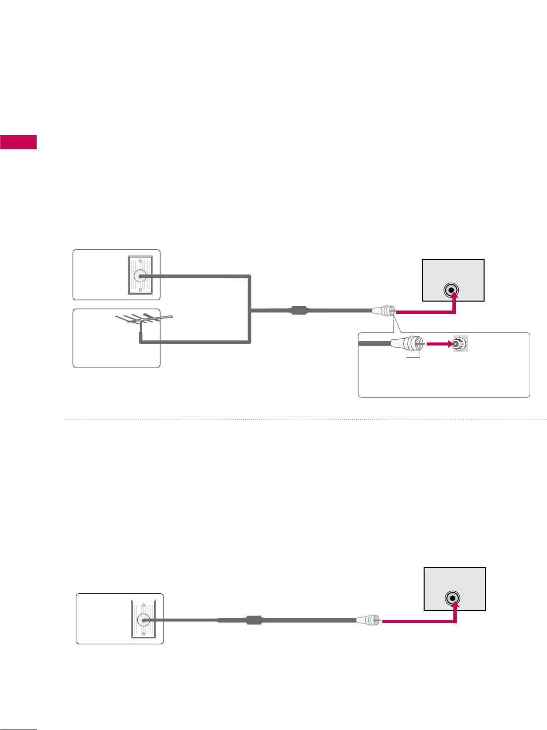
1. Antenna (Analog or Digital)
This image refers to using a Wall Antenna Socket or Outdoor
Antenna without a Cable Box Connection.
2. Cable
Wall
Antenna
Socket
Outdoor
Antenna
(VHF, UHF)
Cable TV
Wall Jack
Multi-family Dwellings/Apartments
(Connect to wall antenna socket)
RF Coaxial Wire (75 Ω)
RF Coaxial Wire (75 Ω)
Single-family Dwellings /Houses
(Connect to wall jack for outdoor antenna)
Be careful not to bend the copper wire
when connecting the antenna.
Copper Wire
- For optimum picture quality, adjust the antenna direction if needed.
■To improve the picture quality in a poor signal area, please purchase a signal amplifier and install properly.
■If the antenna needs to be split for two TV’s, install a 2-Way Signal Splitter.
■If the antenna is not installed properly, contact your dealer for assistance.
■To prevent damage, do not connect to the power outlet until all connections are made between the devices.
ANTENNA INANTENNA IN
This image refers to using a cable connection without a cable box.
- If you experience a poor signal when using cable, make sure the RF cable is screwed in completely.
Contact your cable company is a poor signal persists.
PREPARATION
25
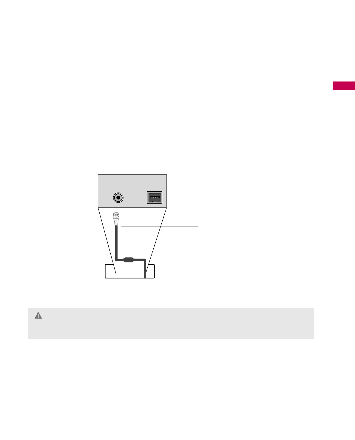
MPI CARD SLOT / PPV CARD INSTALLATION
Except 47/55LD650H
1. Remove the two MPI card retainer screws.
2. Pull out current MPI card far enough so that the RF cable can be detached from the old card.
3. Detach RF cable.
4. Place new PPV card into slot and slide it in far enough to reconnect RF cable.
5. Insert card all the way into the slot making sure it is fully seated into back plane connector.
6. Replace the two card retainer screws.
The MPI card is equipped with an RF jack for antenna/cable signal source connection.
This card can be removed and replaced with a third-party PPV (Pay-Per-View) card.
MPI Card Removal / PPV Card Installation
RF CABLE
ANTENNA IN M.P.I.
M.P. I.
Card Slot
GThere is an RF cable connected to the back of the card. Remove the card slowly.
WARNING
EXTERNAL EQUIPMENT SETUP
26
HD RECEIVER SETUP
EXTERNAL EQUIPMENT SETUP
This TV can receive Digital Over-the-air or Digital Cable signals without an external digital set-top box. However,
if you do receive digital signals from a digital set-top box or other digital external device, refer to the figure as
shown below.
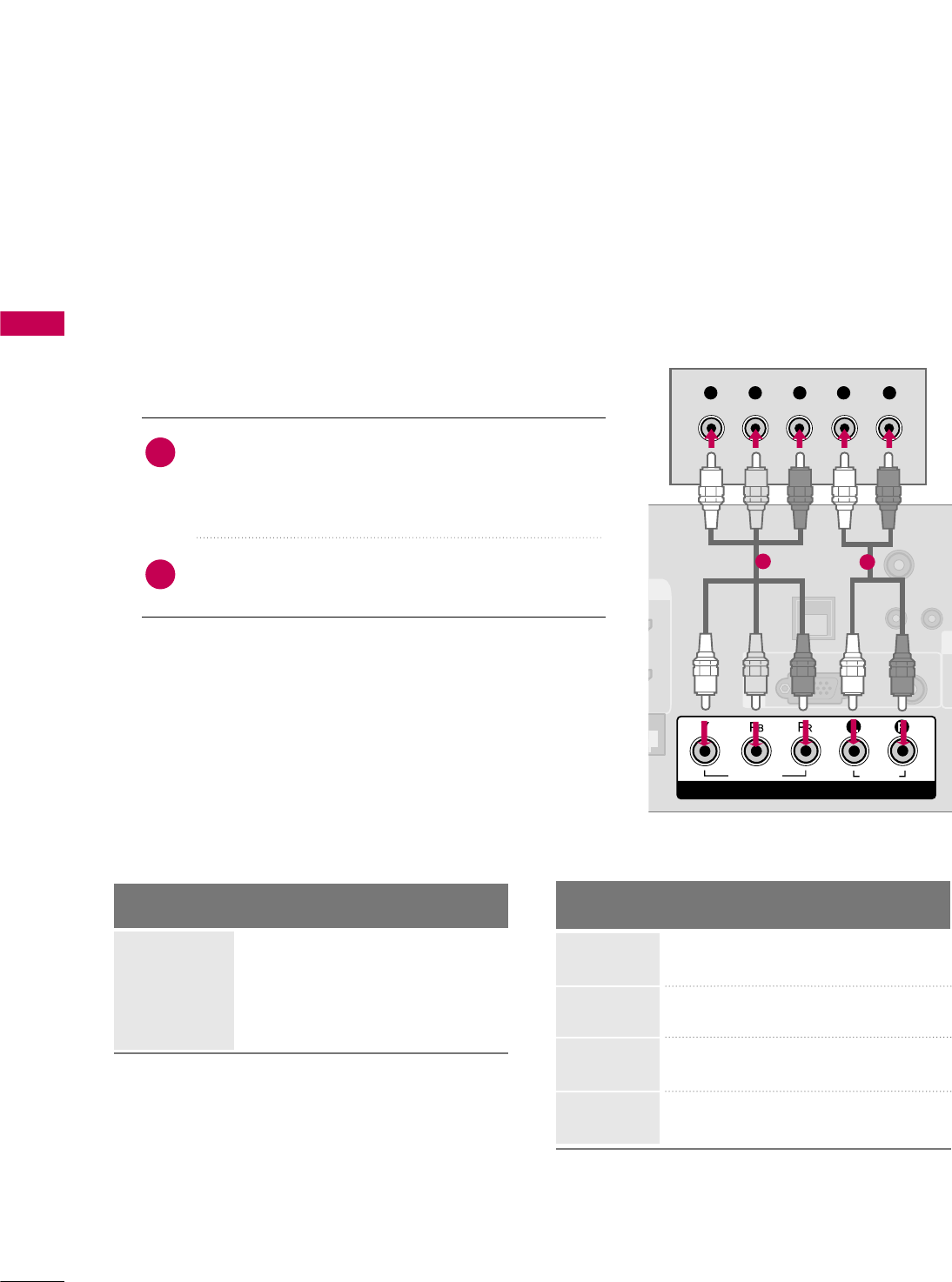
Component Connection
1. How to connect
Connect the video outputs (Y, PB, PR)of the digital set-
top box to the COMPONENT IN VIDEO jacks on
the TV. Match the jack colors (Y = green, PB= blue, and
PR= red).
Connect the audio output of the digital set-top box to
the COMPONENT IN AUDIO jacks on the TV.
2
1
2. How to use
■Turn on the digital set-top box.
(Refer to the owner’s manual for the digital set-top box.)
■Select Component input source using the INPUT button
on the remote control.
■To prevent the equipment damage, never plug in any power cords until you have finished connecting all equipment.
■Image shown may differ from your TV.
U
RESET
LAN
(SERVICE ONLY)
COMPONENT IN
VIDEO
AUDIO
R
(S
VIDEO
AUDIO
COMPONENT IN
RGB(PC) AUDIO
(RGB/DVI)
RGB IN
TV-LINK
CFG
Y L RP
B
P
R
12
Y, CB/PB, CR/PR
Supported Resolutions
Horizontal Vertical
Frequency(KHz)Frequency(Hz)
15.73 59.94
15.73 60.00
31.47 59.94
31.47 60.00
44.96 59.94
45.00 60.00
33.72 59.94
33.75 60.00
Resolution
720x480i
720x480p
1280x720p
1920x1080i
Signal
480i
480p
720p
108 0 i
Component
Yes
Yes
Yes
Yes
HDMI
No
Yes
Yes
Yes
EXTERNAL EQUIPMENT SETUP
27
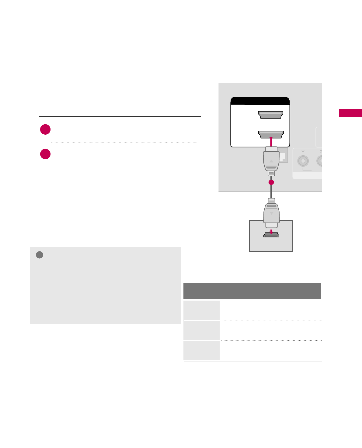
HDMI Connection
Connect the digital set-top box to HDMI/DVI IN 1
(DVI) or 2 jack on the TV.
No separate audio connection is necessary.
HDMI supports both audio and video.
1. How to connect
2. How to use
■Turn on the digital set-top box.
(Refer to the owner’s manual for the digital set-top box.)
■Select HDMI1 or HDMI2 input source with using the INPUT
button on the remote control.
2
1
HDMI-DTV
HDMI/DVI IN
2
1(DVI)
RJP
INTERFACE
VID
RGB
HDMI/DVI IN
2
1(DVI)
HDMI-DTV OUTPUT
1
Horizontal Vertical
Frequency(KHz)Frequency(Hz)
31.47 59.94
31.47 60.00
44.96 59.94
45.00 60.00
33.72 59.94
33.75 60.00
Resolution
720x480p
1280x720p
1920x1080i
GIf the HDMI cables don’t support High Speed
HDMI, it can cause flickers or no screen display. In
this case use the latest cables that support High
Speed HDMI.
GHDMI mode supports PCM, Dolby Digital audio
format.
NOTE
!
EXTERNAL EQUIPMENT SETUP
28
EXTERNAL EQUIPMENT SETUPEXTERNAL EQUIPMENT SETUP
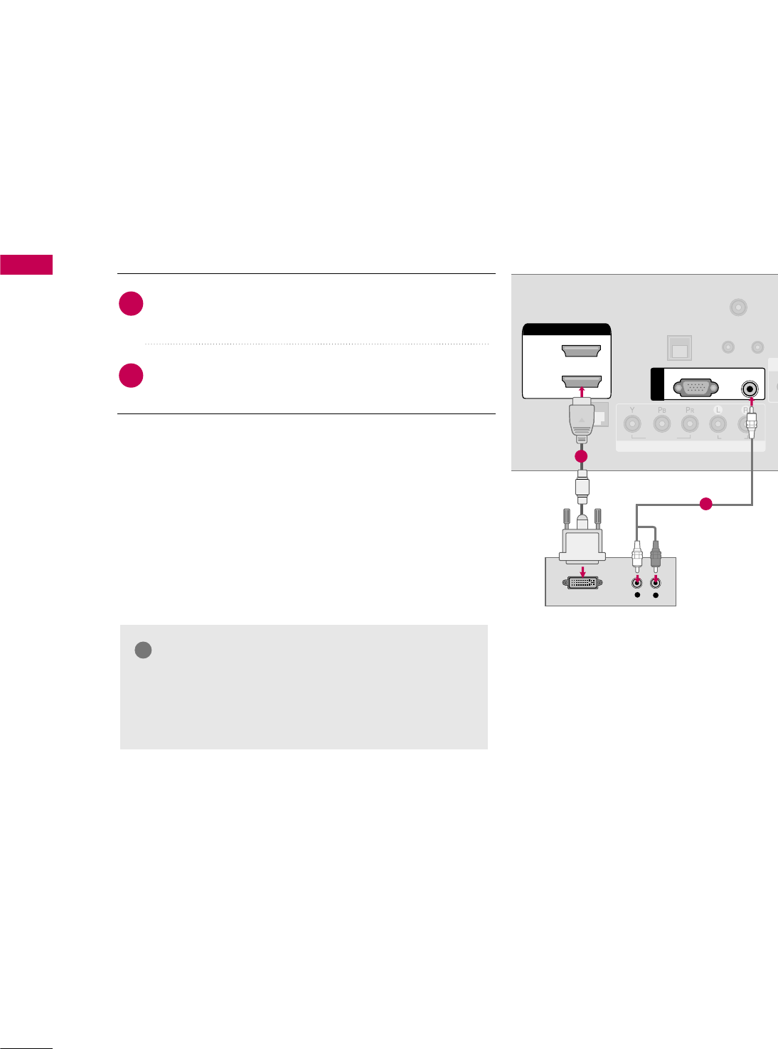
DVI to HDMI Connection
RGB(PC)
AUDIO
(RGB/DVI)
RGB IN
UPDA
RESET
LAN
(SERVICE ONLY)
RJP
INTERFACE
COMPONENT IN
VIDEO
AUDIO
R
(S
HDMI/DVI IN
2
1(DVI)
LR
DVI-DTV OUTPUT
LR
TV-LINK
CFG
CO
1
2
GA DVI to HDMI cable or adapter is required for this
connection. DVI doesn't support audio, so a separate
audio connection is necessary.
NOTE
!
Connect the DVI output of the digital set-top box to
the HDMI/DVI IN 1 (DVI) jack on the TV.
Connect the audio output of the digital set-top box to
the AUDIO (RGB/DVI) jack on the TV.
1. How to connect
2. How to use
■Turn on the digital set-top box. (Refer to the owner’s man-
ual for the digital set-top box.)
■Select the HDMI1 input source on the TV using the
INPUT button on the remote control.
2
1
EXTERNAL EQUIPMENT SETUP
29
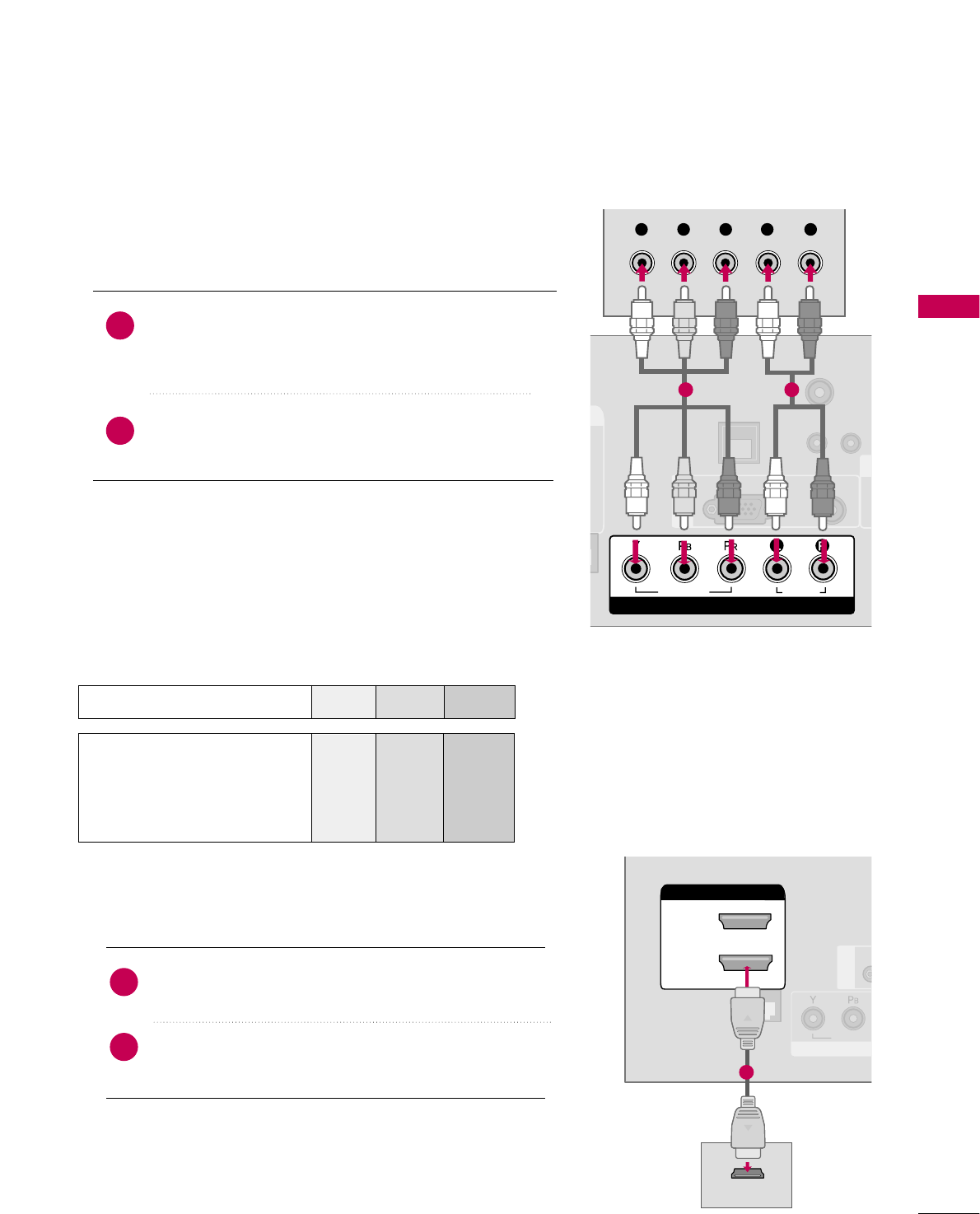
DVD SETUP
Component Connection
Component Input ports
To get better picture quality, connect a DVD player to the component input ports as shown below.
Component ports on the TV
YPBPR
Video output ports
on DVD player
Y
Y
Y
Y
PB
B-Y
Cb
Pb
PR
R-Y
Cr
Pr
Connect the video outputs (Y, PB, PR)of the DVD to the
COMPONENT IN VIDEO jacks on the TV.
Match the jack colors (Y = green, PB= blue, and PR= red).
Connect the audio outputs of the DVD to the
COMPONENT IN AUDIO jacks on the TV.
1. How to connect
2. How to use
■Turn on the DVD player, insert a DVD.
■Select the Component input source on the TV using the
INPUT button on the remote control.
■Refer to the DVD player's manual for operating instructions.
2
1
U
RESET
LAN
(SERVICE ONLY)
COMPONENT IN
VIDEO
AUDIO
R
(S
VIDEO
AUDIO
COMPONENT IN
RGB(PC) AUDIO
(RGB/DVI)
RGB IN
TV-LINK
CFG
Y L RP
B
P
R
1 2
HDMI Connection
Connect the HDMI output of the DVD to the
HDMI/DVI IN 1 (DVI) or 2jack on the TV.
No separate audio connection is necessary.
HDMI supports both audio and video.
1. How to connect
2. How to use
■Select the HDMI1 or HDMI2 input source on the TV
using the INPUT button on the remote control.
■Refer to the DVD player's manual for operating instructions.
2
1
(S
HDMI/DVI IN
2
1(DVI)
RJP
INTERFACE
COM
VIDEO
HDMI/DVI IN
2
1(DVI)
HDMI OUTPUT
RGB IN
1
EXTERNAL EQUIPMENT SETUP
30
EXTERNAL EQUIPMENT SETUPEXTERNAL EQUIPMENT SETUP
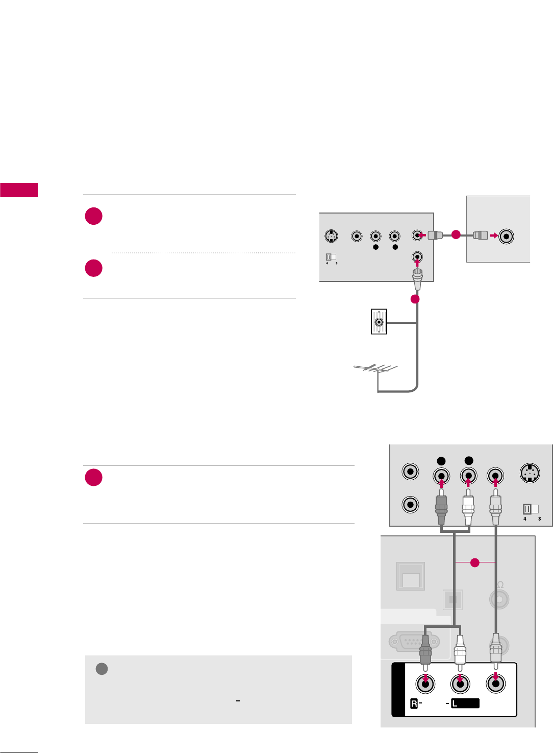
VCR SETUP
Antenna Connection
■To avoid picture noise (interference), leave an adequate distance between the VCR and TV.
L R
S-VIDEO VIDEO
OUTPUT
SWITCH
ANT IN
ANT OUT
ANTENNA INANTENNA IN
Wall Jack
Antenna
1
2
Connect the RF antenna out socket of the
VCR to the ANTENNA IN socket on the
TV.
Connect the antenna cable to the RF
antenna in socket of the VCR.
1. How to connect
2. How to use
■Set VCR output switch to 3 or 4 and then
tune TV to the same channel number.
■Insert a video tape into the VCR and press
PLAY on the VCR. (Refer to the VCR owner’s
manual.)
2
1
Composite (RCA) Connection
Connect the AUDIO/VIDEO jacks between TV and
VCR. Match the jack colors (Video = yellow, Audio Left
= white, and Audio Right = red)
1. How to connect
2. How to use
■Insert a video tape into the VCR and press PLAY on the
VCR. (Refer to the VCR owner’s manual.)
■Select the AV 1 input source on the TV using the INPUT
button on the remote control.
■If connected to AV IN 2, select AV2 input source on the TV.
1
GIf you have a mono VCR, connect the audio cable
from the VCR to the AUDIO L/MONO jack of the
TV.
NOTE
!
L
R
S-VIDEO
VIDEO
OUTPUT
SWITCH
ANT IN
ANT OUT
OPTICAL
DIGITAL
AUDIO OUT
UPDATE
AV IN 1
AUDIO
VIDEO
/
REMOTE
CONTROL
OUT
SPEAKER
OUT
8
RS-232C IN
(SERVICE ONLY)
MONO
/
AV IN 1
AUDIO
VIDEO
MONO
/
GAME
CONTROL
1
EXTERNAL EQUIPMENT SETUP
31
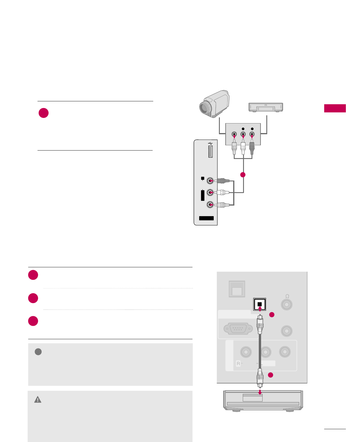
OTHER A/V SOURCE SETUP
AV IN 2
L/MONO
R
AUDIO
VIDEO
USB IN
L R
VIDEO
Camcorder
Video Game Set
Connect the AUDIO/VIDEO jacks
between TV and external equipment.
Match the jack colors
.
(Video = yellow, Audio Left = white, and
Audio Right = red)
1. How to connect
2. How to use
■Select the AV2 input source on the TV using the
INPUT button on the remote control.
■If connected to AV IN 1 input, select the AV1
input source on the TV.
■Operate the corresponding external equipment.
1
1
Connect one end of the optical cable to the TV’s OPTI-
CAL DIGITAL AUDIO OUT.
Connect the other end of the optical cable to the digital
audio input on the audio equipment.
Set the “TV Speaker option - Off” in the AUDIO menu. (G
p.73). See the external audio equipment instruction manu-
al for operation.
AUDIO OUT CONNECTION
Send the TV’s audio to external audio equipment via the Audio Output port.
UPDATE
AV IN 1
AUDIO
VIDEO
/
REMOTE
CONTROL
OUT
SPEAKER
OUT
8
RS-232C IN
(SERVICE ONLY)
MONO
/
OPTICAL
DIGITAL
AUDIO OUT
GAME
CONTROL
1
2
GWhen connecting with external audio equipment, such as
amplifiers or speakers, you can turn the TV speakers off in
the menu. (G p.73)
NOTE
!
GDo not look into the optical output port. Looking at the
laser beam may damage your vision.
GGAudio with ACP(Audio Copy Protection) function my
block digital audio output.
CAUTION
1. How to connect
2
3
1
EXTERNAL EQUIPMENT SETUP
32
EXTERNAL EQUIPMENT SETUP
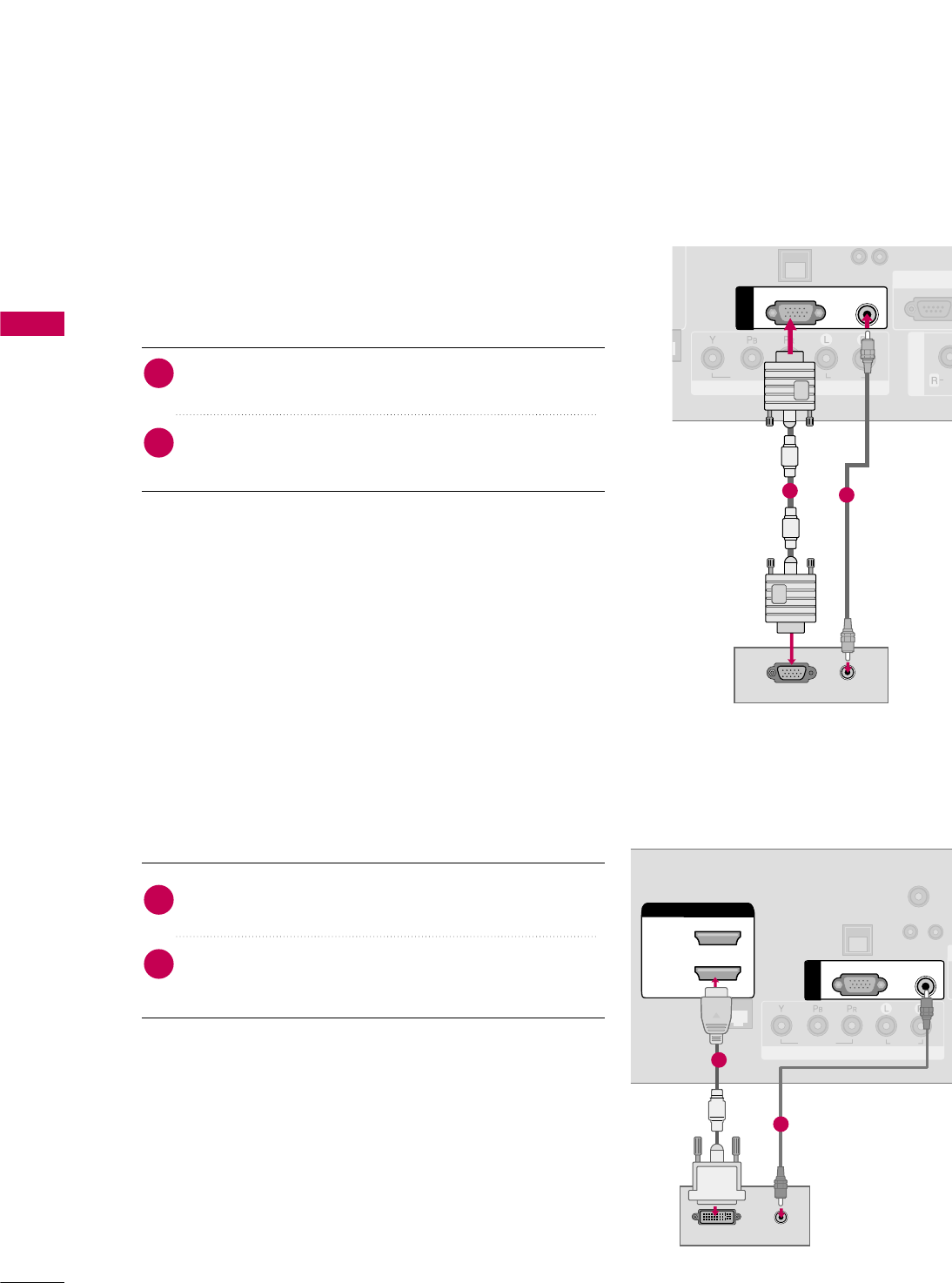
PC SETUP
This TV provides Plug and Play capability, meaning that the PC adjusts automatically to the TV's settings.
VGA (D-Sub 15 pin) Connection
UPDATE
RESET
()
COMPONENT IN
VIDEO
AUDIO
AV IN 1
AU
RS-232C IN
(SERVICE ONLY
AUDIO
RGB OUTPUT
RGB(PC)
AUDIO
(RGB/DVI)
RGB IN
12
2. How to use
■Turn on the PC and the TV.
■Select the RGB-PC input source on the TV using the
INPUT button on the remote control.
Connect the VGA output of the PC to the RGB (P C)
jack on the TV.
Connect the PC audio output to the AUDIO (RGB/DVI)
jack on the TV.
1. How to connect
2
1
DVI to HDMI Connection
UP
RESET
LAN
(SERVICE ONLY)
RJP
INTERFACE
COMPONENT IN
VIDEO
AUDIO
(S
HDMI/DVI IN
2
1(DVI)
DVI-PC OUTPUT AUDIO
RGB(PC)
AUDIO
(RGB/DVI)
RGB IN
TV-LINK
CFG
1
2
2. How to use
■Turn on the PC and the TV.
■Select the HDMI1 input source on the TV using the
INPUT button on the remote control.
Connect the DVI output of the PC to the HDMI/DVI IN
1 (DVI) jack on the TV.
Connect the PC audio output to the AUDIO (RGB/DVI)
jack on the TV.
1. How to connect
2
1
EXTERNAL EQUIPMENT SETUP
33
GTo get the best picture quality, adjust the PC graph-
ics card to 1360x768.
GDepending on the graphics card, DOS mode may
not work if a HDMI to DVI Cable is in use.
GIn PC mode, there may be noise associated with
the resolution, vertical pattern, contrast or bright-
ness. If noise is present, change the PC output to
another resolution, change the refresh rate to
another rate or adjust the brightness and contrast
on the PICTURE menu until the picture is clear.
When you use too long RGB-PC cable, there might
be a noise on the screen.
GAvoid keeping a fixed image on the screen for a
long period of time. The fixed image could become
permanently imprinted on the screen.
GThe synchronization input form for Horizontal and
Vertical frequencies is separate.
GDepending on the graphics card, some resolution
settings may not allow the image to be positioned
on the screen properly.
NOTES
!
Supported Display Specifications
Resolution
720x400
1360x768
640x480
800x600
1024x768
1280x768
1280x1024
1920x1080
Horizontal Vertical
Frequency(KHz)Frequency(Hz)
31.469 70.08
31.469 59.94
35.156 56.25
37.879 60.31
48.363 60.00
47.776 59.87
47.712 60.015
63.981 60.02
67.50 60.00
Resolution
720x400
1360x768
640x480
800x600
1024x768
1280x768
1280x1024
1920x1080
Horizontal Vertical
Frequency(KHz)Frequency(Hz)
31.469 70.08
31.469 59.94
37.861 72.80
37.879 60.31
48.077 72.18
48.363 60.00
56.476 70.06
47.776 59.870
60.289 74.893
47.712 60.015
63.981 60.020
79.976 75.025
66.587 59.934
HDMI-PCRGB-PC
Depending on models
Depending on models
EXTERNAL EQUIPMENT SETUP
34
EXTERNAL EQUIPMENT SETUP
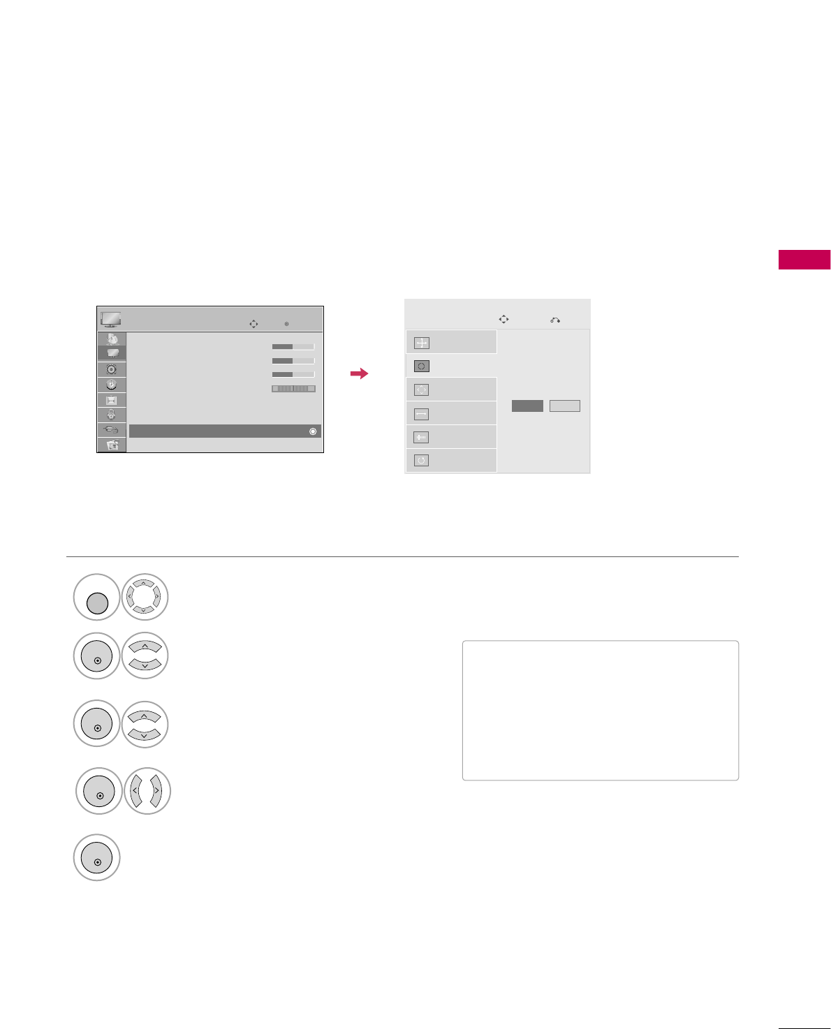
Screen Setup for PC mode
Selecting Resolution
When using RGB-PC input, change the resolution in the menus to match the PC’s.
The P
Position, Phase, and Size can also be adjusted.
Select PICTURE.
Select Resolution.
1
MENU
3
ENTER
4
Select Screen (RGB-PC).
2
ENTER
5
Select the desired resolution.
ENTER
ENTER
Auto Config.
Resolution
Position
Size
Phase
Reset
SCREEN
Move
Prev.
Enter
Move
PICTURE
E
RG
• Brightness 50
• Sharpness 50
• Color 50
• Tint 0
• Advanced Control
• Picture Reset
Screen (RGB-PC)
1024 x 768
1280 x 768
1360 x 768
EXTERNAL EQUIPMENT SETUP
35
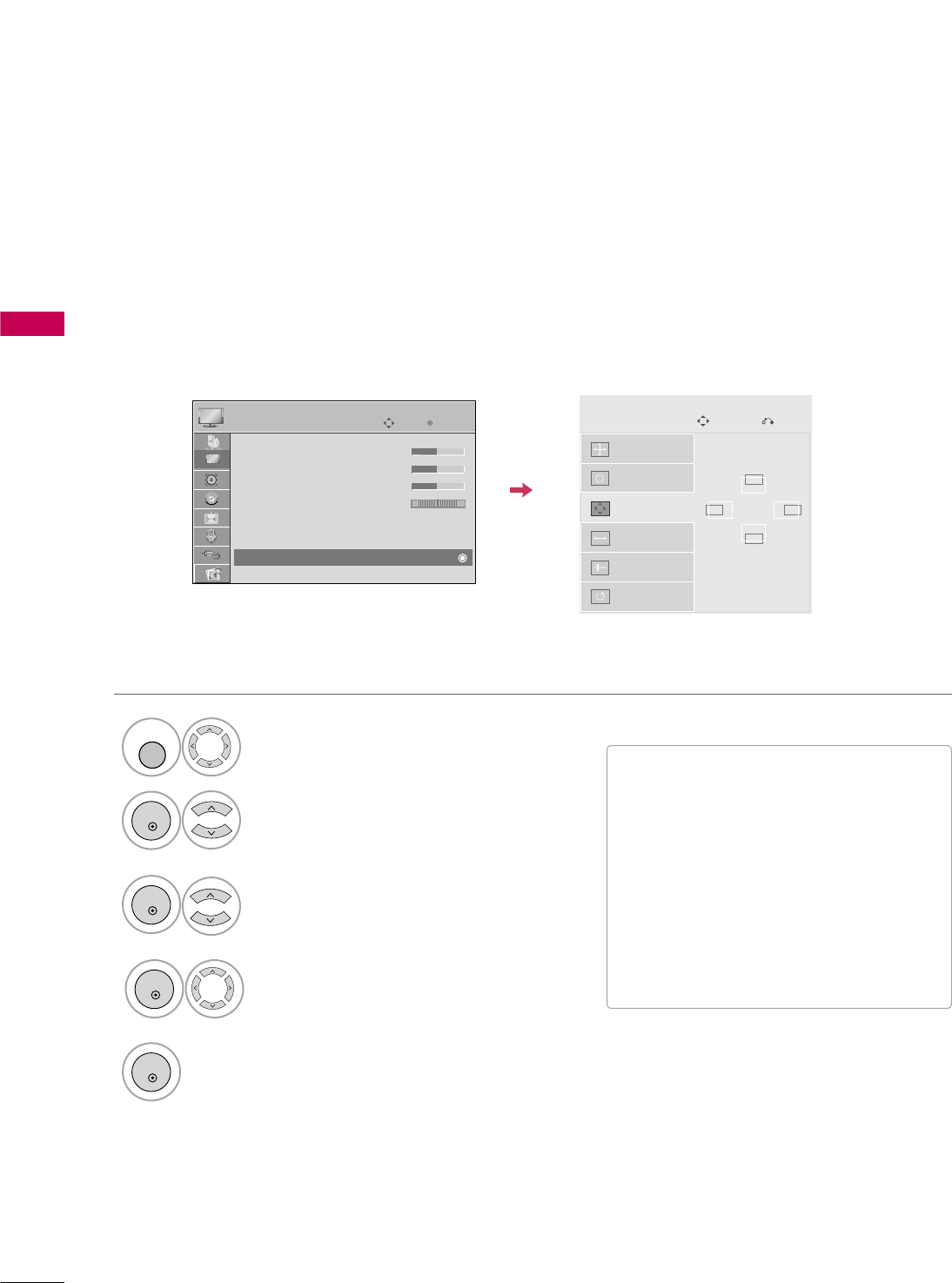
Auto Configure
Automatically adjusts picture position and minimizes image instability. After adjustment, if the image is still
not correct, try using the manual settings or a different resolution or refresh rate on the PC.
• If the position of the image is still not
correct, try Auto adjustment again.
• If picture needs to be adjusted again
after Auto adjustment in RGB-PC, you
can adjust the P os iti on, Size or
Phase.
Select PICTURE.
Select Auto config..
1
MENU
3
ENTER
4
Select Screen (RGB-PC).
2
ENTER
5
ENTER
Start Auto Configuration.
Select Yes.
ENTER
Auto Config.
Resolution
Position
Size
Phase
Reset
SCREEN
Move
Prev.
To Set
Yes No
Enter
Move
PICTURE
E
RG
• Brightness 50
• Sharpness 50
• Color 50
• Tint 0
• Advanced Control
• Picture Reset
Screen (RGB-PC)
EXTERNAL EQUIPMENT SETUP
36
EXTERNAL EQUIPMENT SETUP
Adjustment for screen Position, Size, and Phase
If the picture is not clear after auto adjustment and especially if characters are still trembling, adjust the picture
phase manually.
This feature operates only in RGB-PC mode.
■Position: This function is to adjust pic-
ture to left/right and up/down as you
prefer.
■Size: This function is to minimize any
vertical bars or stripes visible on the
screen background. And the horizontal
screen size will also change.
■Phase: This function allows you to
remove any horizontal noise and clear or
sharpen the image of characters.
Select PICTURE.
Select Position, Size, or Phase.
1
MENU
3
ENTER
4
Select Screen (RGB-PC).
2
ENTER
5
ENTER
Make appropriate adjustments.
ENTER
Auto Config.
Resolution
Position
Size
Phase
Reset
GF
D
E
SCREEN
Move
Prev.
Enter
Move
PICTURE
E
RG
• Brightness 50
• Sharpness 50
• Color 50
• Tint 0
• Advanced Control
• Picture Reset
Screen (RGB-PC)
EXTERNAL EQUIPMENT SETUP
37
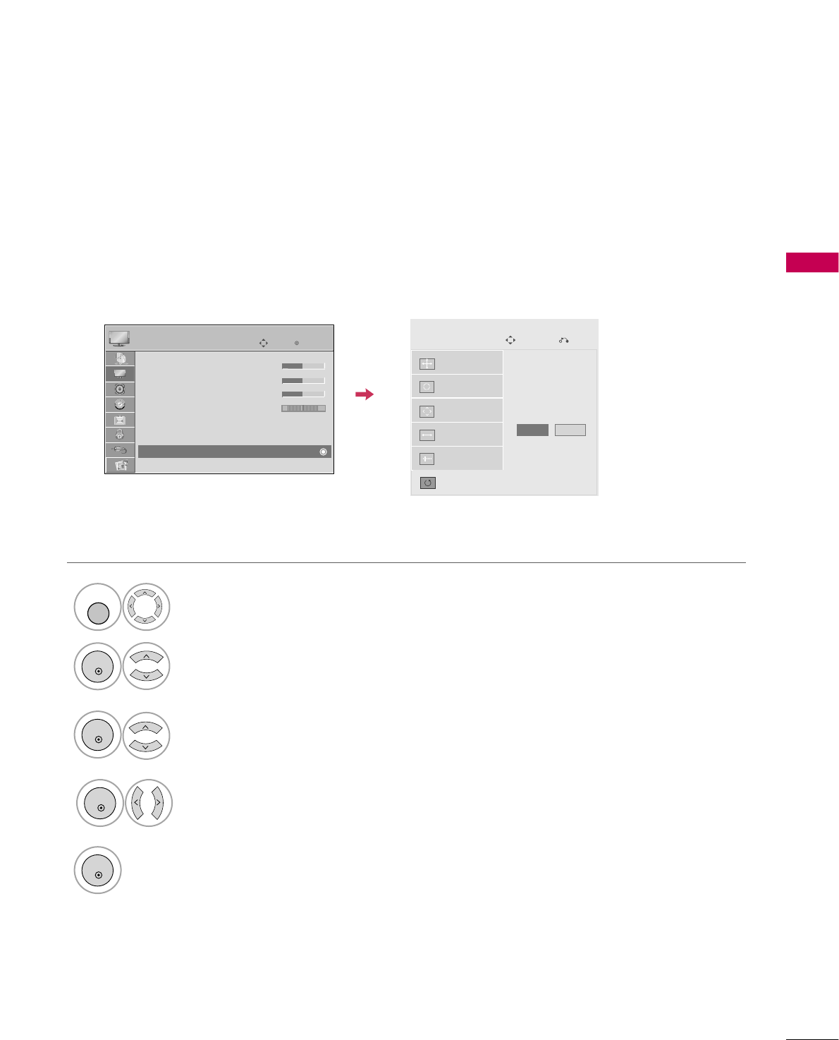
Screen Reset (Reset to original factory values)
Returns Position, Size, and Phase to the default factory settings.
This feature operates only in RGB-PC mode.
Select PICTURE.
Select Reset.
1
MENU
3
ENTER
4
Select Screen (RGB-PC).
2
ENTER
5
ENTER
Select Yes.
ENTER
Auto config.
Position
Resolution
Size
Phase
Reset
SCREEN
Move
Prev.
To Set
Yes No
Enter
Move
PICTURE
E
RG
• Brightness 50
• Sharpness 50
• Color 50
• Tint 0
• Advanced Control
• Picture Reset
Screen (RGB-PC)
WATCHING TV / CHANNEL CONTROL
38
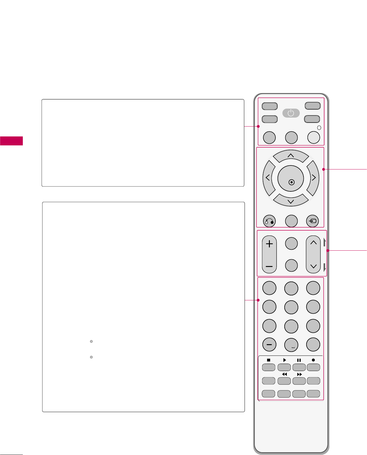
REMOTE CONTROL FUNCTIONS
When using the remote control, aim it at the remote control sensor on the TV.
MUTE
RETURN
CC
TV
POWER
GUIDE
PORTAL
ENTER
VOL CH
123
456
78
0
9
FLASHBK
VCR
DVD
INPUT
MENU
INFO
i
STB
P
A
G
E
PIP SAP
PIP CH- PIP CH+
PIP SWAP
PIP INPUT
ALPHA/NUM
REMOVE
RATIO
TIMER
ABC DEF
GHI
WXYZ
TUV
PQRS
MNO
JKL
&@
.:/,
POWER
TV/STB/DVD/VCR
GUIDE
PORTAL
INFO
Turns your TV or any other programmed equipment on
or off, depending on mode.
Select the remote’s operating mode: TV, STB, DVD, or
VCR.
Displays and removes the electronic channel guide.
Displays and removes the hotel interactive menu.
Displays information about the selected or current event.
NUMBER
button
— (DASH)
FLASHBK
VCR/DVD/USB
control buttons
PIP
RATIO
TIMER
SAP
PIP CH +/-
PIP SWAP
PIP INPUT
Enter channel numbers or other numbers required. Also
supports characters.
Used to enter a program number for multiple program
channels such as 2-1, 2-2, etc.
Tune to the last channel or input viewed.
Control video cassette recorders or DVD players or USB.
Toggles through picture-in-picture options.
Change the aspect ratio. Gp.58
Turns the TV off in a set amount o f time. Gp.84
Analog mode: Selects MTS sound (Mono, Stereo, or a
SAP) Gp.75
DTV mode: Changes the audio language.
Changes the PIP channel.
Exchange the main/sub images.
Select the connected input source for the sub-picture.
WATCHING TV / CHANNEL CONTROL
WATCHING TV / CHANNEL CONTROL
39
Installing Batteries
■
Open the battery compartment cover on the back side and install
the batteries matching correct polarity (+with +,-with -).
■
Install two 1.5V AAA batteries. Don’t mix old or used batteries with
new ones.
■
Close cover.
THUMBSTICK
(Up/Down/Left
Right/ENTER)
RETURN
MENU
INPUT
Navigate the on-screen menus and adjust the system settings to your preference.
Clears all on-screen displays and returns to TV viewing from any menu.
Displays the main menu.
External input modes rotate in regular sequence: TV, AV1-2, Component, RGB-PC,
HDMI1 and HDMI2.
VOLUME UP
/DOWN
CC
MUTE
CHANNEL
UP/DOWN
PAGE
UP/DOWN
Increase/decrease the sound level.
Select a closed caption. Gp.82
Switch the sound on or off. Gp.40
Select available channels.
Move from one full set of screen information to the next one.
WATCHING TV / CHANNEL CONTROL
40
WATCHING TV / CHANNEL CONTROL
TURNING ON TV
WATCHING TV / CHANNEL CONTROL
NOTE
!
GIf you intend to be away on vacation, disconnect the power plug from the wall power outlet.
Press the CH( or )or NUMBER buttons to select a channel number.
1
VOLUME ADJUSTMENT
CHANNEL SELECTION
Press the VOL (+ or -) button to adjust the volume.
If you want to switch the sound off, press the MUTE button.
You can cancel the Mute function by pressing the MUTE or VOL (+ or -)
button.
Adjust the volume to suit your personal preference.
1
2
3
First, connect power cord correctly.
At this moment, the TV switches to standby mode.
■In standby mode to turn TV on, press the button on the TV or press
the POWER button on the remote control.
Select the viewing source by using the INPUT button on the remote control.
■This TV is programmed to remember which power state it was last set to,
even if the power cord is out.
When finished using the TV, press the POWER button on the remote control.
The TV reverts to standby mode.
1
2
3
WATCHING TV / CHANNEL CONTROL
41
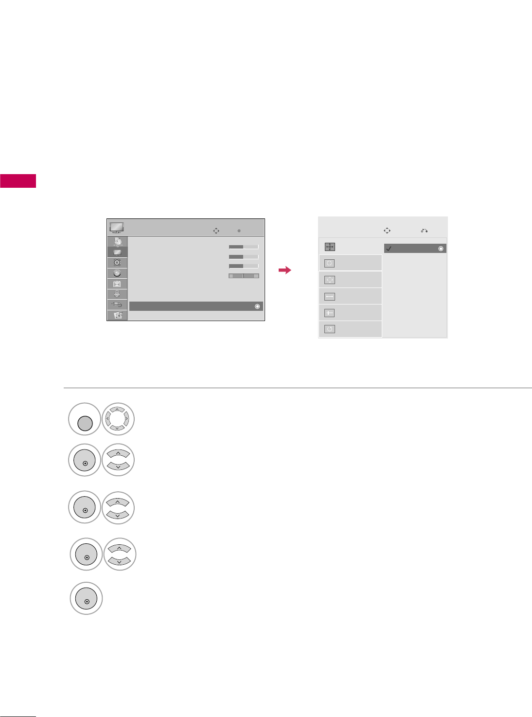
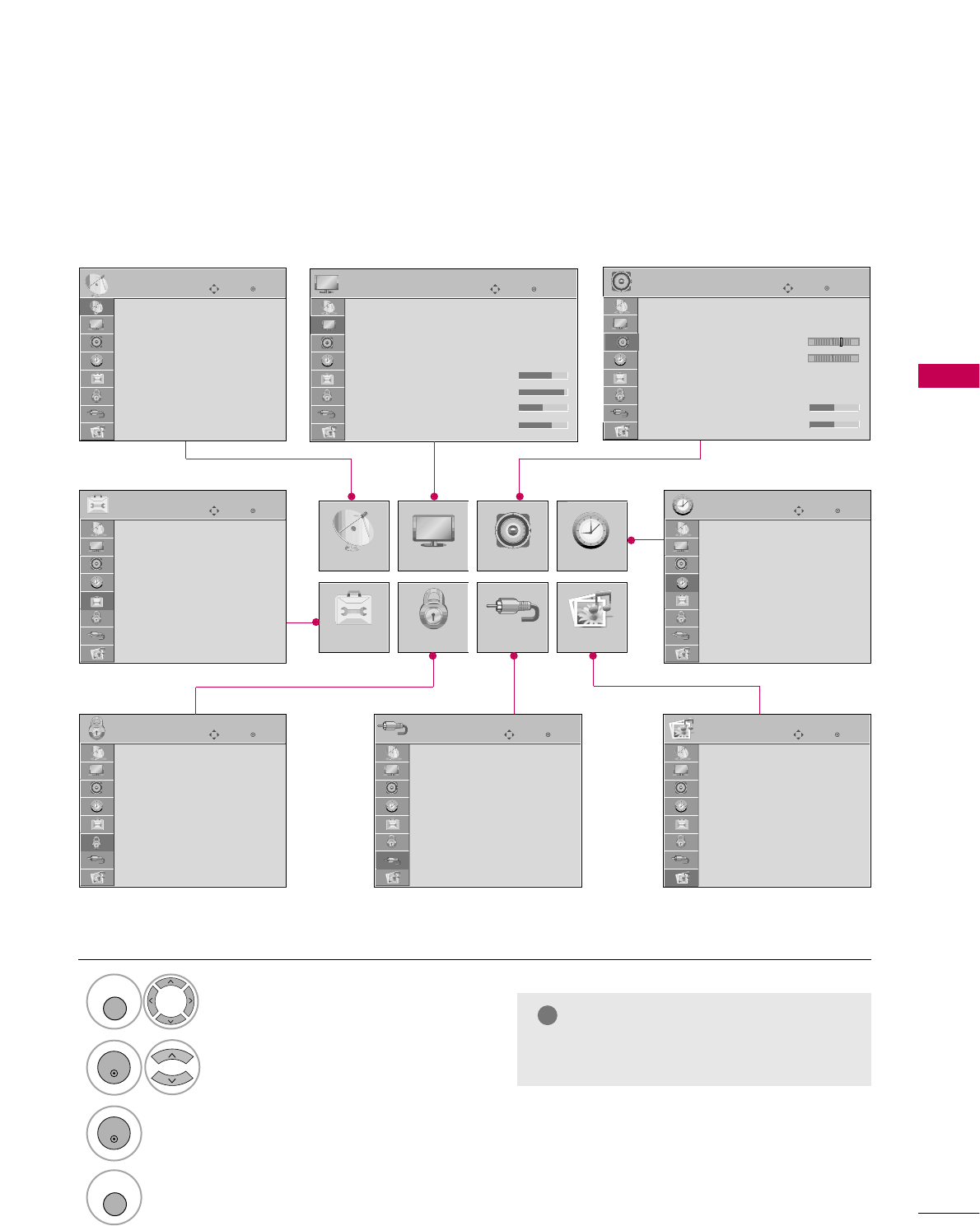
ON-SCREEN MENUS SELECTION
Your TV's OSD (On Screen Display) may differ slightly from that shown in this manual.
Display each menu.
Select a menu item.
Accept the current selection.
1
MENU
3
2
ENTER
ENTER
Return to TV viewing.
4
MENU
Enter
Move
Auto Tuning
Manual Tuning
Channel Edit
Channel Label
CHANNEL
CHANNEL
OPTION
PICTURE
LOCK
AUDIO
INPUT
TIME
USB
Enter
Move
Auto Volume : On
Clear Voice II : On
• Level 3
Balance 0
Sound Mode : Standard
•
SRS TruSurround XT:
Off
• Treble 50
• Bass 50
AUDIO
E
Enter
Move
Clock
Off Time : Off
On Time : Off
Sleep Timer : Off
TIME
Enter
Move
Photo List
Music List
Extra Contents
Eject
USB
Enter
Move
TV
AV1
AV2
Component
RGB-PC
HDMI1
HDMI2
INPUT
Enter
Move
Lock System : Off
Set Password
Block Channel
Movie Rating
TV Rating-Children
TV Rating-General
Downloadable Rating
Input Block
LOCK
Enter
Move
Menu Language : English
Audio Language : English
Caption : Off
Set ID : 1
Demo Mode : Off
Data Broadcasting
OPTION
LR
-+
Enter
Move
Aspect Ratio : 16:9
Picture Mode : Standard
• BackLight 90
• Contrast 90
• Brightness 50
• Sharpness 60
• Color 60
• Tint 0
PICTURE
E
NOTE
!
GInfinite Sound: For 32/37/42/47/55LD650H
WATCHING TV / CHANNEL CONTROL
42
WATCHING TV / CHANNEL CONTROL
Enter
Move
CHANNEL
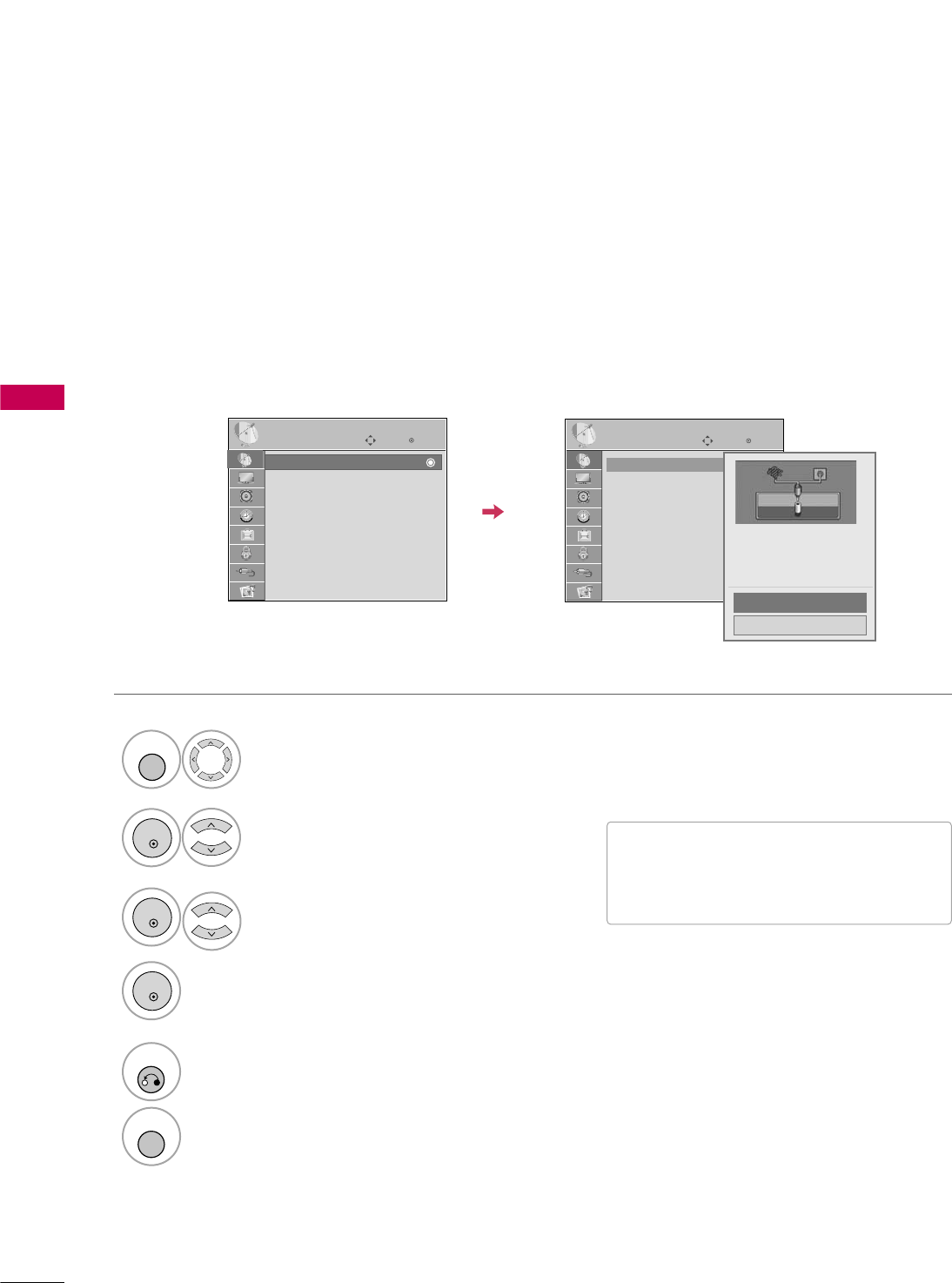
Auto Scan (Auto Tuning)
Automatically finds all channels available through antenna or cable inputs and stores them in memory on the
channel list.
Run Auto Tuning again after any Antenna/Cable connection changes.
Select CHANNEL.
Select Auto Tuning.
Select Yes.
Run Auto tuning.
1
MENU
3
2
ENTER
ENTER
4
ENTER
■A password is required to gain access to
Auto Tuning menu if the Lock System is
turned on.
5
RETURN
Return to the previous menu.
MENU
Return to TV viewing.
CHANNEL SETUP
Auto Tuning
Manual Tuning
Channel Edit
Channel Label
Enter
Move
CHANNEL
Auto Tuning
Manual Tuning
Channel Edit
Channel Label
Check your antenna connection.
The previous channel information
will be updated during Auto
Tuning.
Yes
No
WATCHING TV / CHANNEL CONTROL
43
Select CHANNEL.
1
MENU
2
ENTER
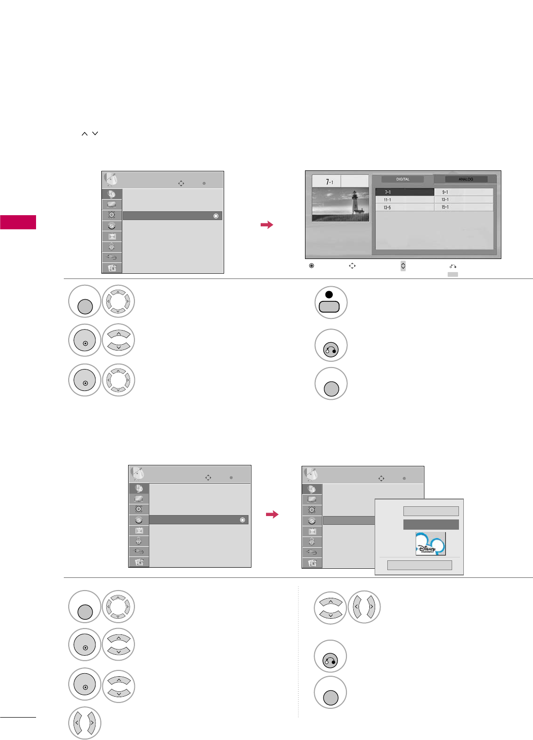
If selecting DIGITAL input signal, you can view the on-screen signal strength monitor to see the quality of the
signal being received.
Add/Delete Channel (Manual Tuning)
Select Manual Tuning.
Select DIGITAL or ANALOG.
Select channel you want to add
or delete.
3
ENTER
4
Select Add or Delete.
5
ENTER
■A password is required to gain access to
Manual Tuning menu if the Lock System
is turned on.
6
RETURN
Return to the previous menu.
MENU
Return to TV viewing.
Enter
Move
CHANNEL
Enter
Move
CHANNEL
Channel
Select channel type and
RF-channel number.
F
DIGITAL
G
2
Close
Delete
DIGITAL 2-1
Bad Normal Good
Auto Tuning
Manual Tuning
Channel Edit
Channel Label
Auto Tuning
Manual Tuning
Channel Edit
Channel Label
WATCHING TV / CHANNEL CONTROL
44
WATCHING TV / CHANNEL CONTROL
CHANNEL LABEL
Select a channel.
Select channel you want to add or delete.
3
ENTER
4
BLUE
The channels in the Channel Edit List are displayed in black and the channels deleted from the Channel Edit
List are displayed in blue. When a channel number is deleted, it means that you will be unable to select it using
CH button during TV viewing.
If you wish to select the deleted channel, directly enter the channel number with the NUMBER buttons or select
it in the Channel Edit menu.
Channel Editing
Select CHANNEL.
1
MENU
2
ENTER
Select Channel Edit.
MENU
Return to TV viewing.
Return to the previous menu.
5
RETURN
Choose preset labels for your channels.
If a channel label is provided on the signal from the broadcasting station, the TV displays a short name for a
channel even if you didn't preset a label for the channel.
Select CHANNEL.
Select Channel Label.
Select a Channel.
1
MENU
3
2
ENTER
ENTER
Select the appropriate logo for the
channel.
5
Select a channel to set logo.
4
6
RETURN
Return to the previous menu.
MENU
Return to TV viewing.
Enter
Move
CHANNEL
Auto Tuning
Manual Tuning
Channel Edit
Channel Label
Ch. Change Page Change
CH
Navigation Previous
Add/Delete
Enter
Move
CHANNEL
Auto Tuning
Manual Tuning
Channel Edit
Channel Label
Enter
Move
CHANNEL
Auto Tuning
Manual Tuning
Channel Edit
Channel Label Logo F Disney G
Channel ANALOG 2-0
Close
WATCHING TV / CHANNEL CONTROL
45
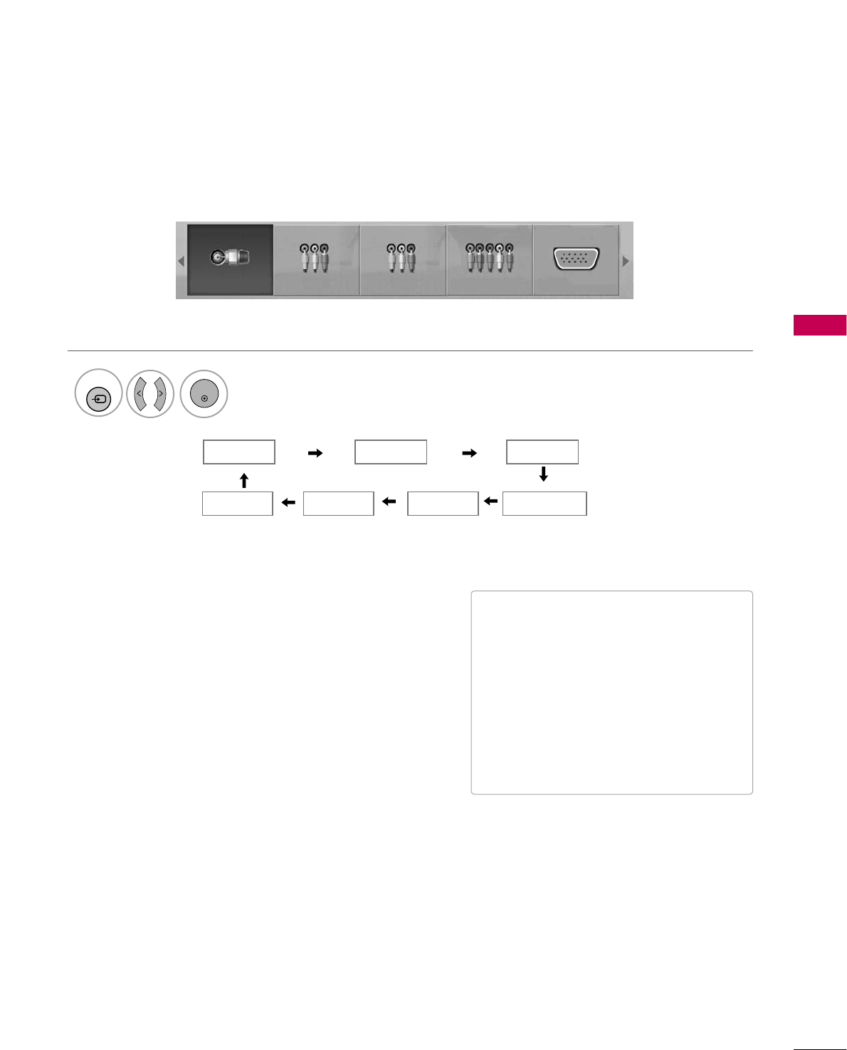
INPUT LIST
Select the desired input source.
1
INPUT
TV AV1 AV2
ComponentHDMI1 RGB-PC
TV AV1 AV2 Component RGB-PC
ENTER
■T V: Select it to watch over-the-air, cable
and digital cable broadcasts.
■AV1-2: Select them to watch a VCR or
other external equipment.
■Component: Select them to watch
DVD or a Digital set-top box.
■RGB-PC: Select it to view PC input.
■HDMI1-2: Select them to watch high
definition devices.
HDMI2
WATCHING TV / CHANNEL CONTROL
46
WATCHING TV / CHANNEL CONTROL
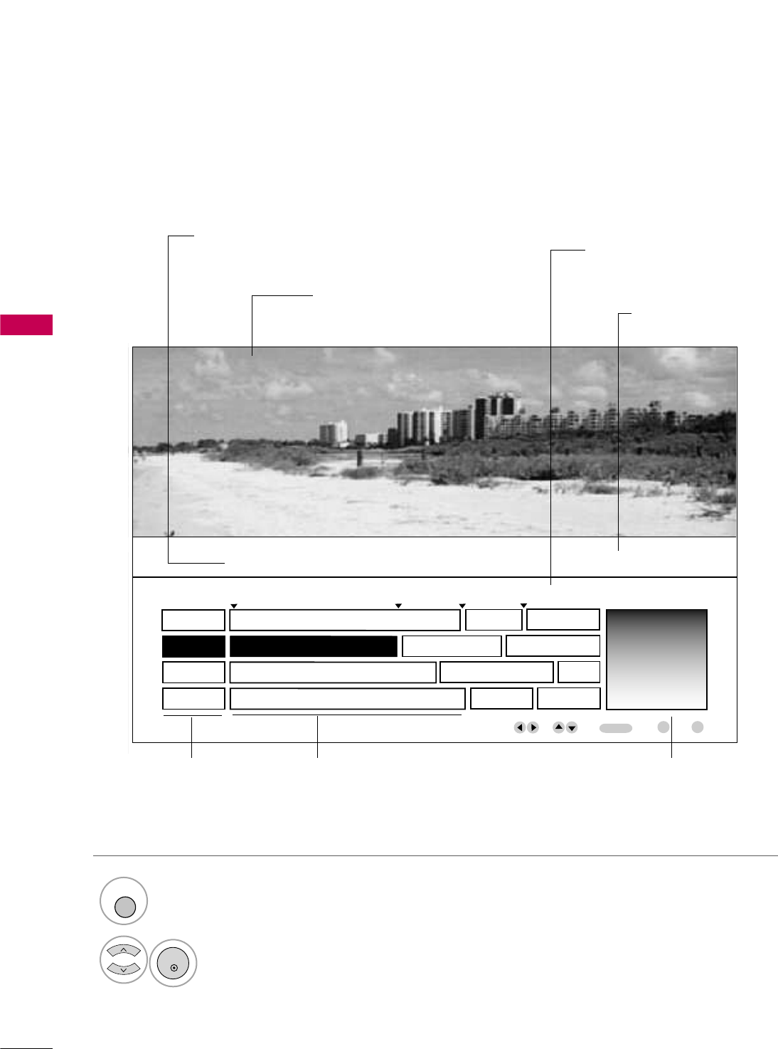
EXAMPLE ELECTRONIC PROGRAM GUIDE
This is an example of a typical TV electronic program guide showing available programming.
On The Political Scene
Kids Movies
Top Fashions
World Events Today
Channel 01:30 AM 2:30 AM 2:45 AM 3:00 AM
Kids ... Kids ...
Kids Movies
K&M
17 XYZ
18 K&M
19 PQX
20 WBD
Mon. 29 May 2009 11:07
New Release
Greatest Hits
Kids
EVENT
CHANNEL
SELECTION
PORTAL
INFO
ENTER
PROGRAMMING GRID
Program listings arranged in
time slots.
CHANNEL LIST
Shows available
channels in numerical
order.
DATE/TIME OSD
Shows current Date/Time.
CHANNEL INDICATOR
Currently tuned channel
and program.
PROGRAM TITLES
Highlight a title and press
Enter to display additional
program information.
FEATURED ATTRACTION
Highlight and click to get
expanded information.
TV PROGRAM
Current program on select-
ed channel.
Select GUIDE button to shows available TV programs.
1
GUIDE
Select a Channel.
2
ENTER
USB
47
USB
USB IN
R
Memory Key
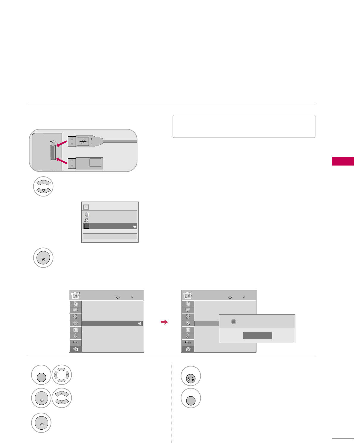
Connect the USB device to the USB IN
jacks on the side of TV.
3
Select PHOTO LIST or MUSIC LIST or EXTRA CONTENTS.
1
2
■This TV Supports playback of JPG pictures and
MP3 audio.
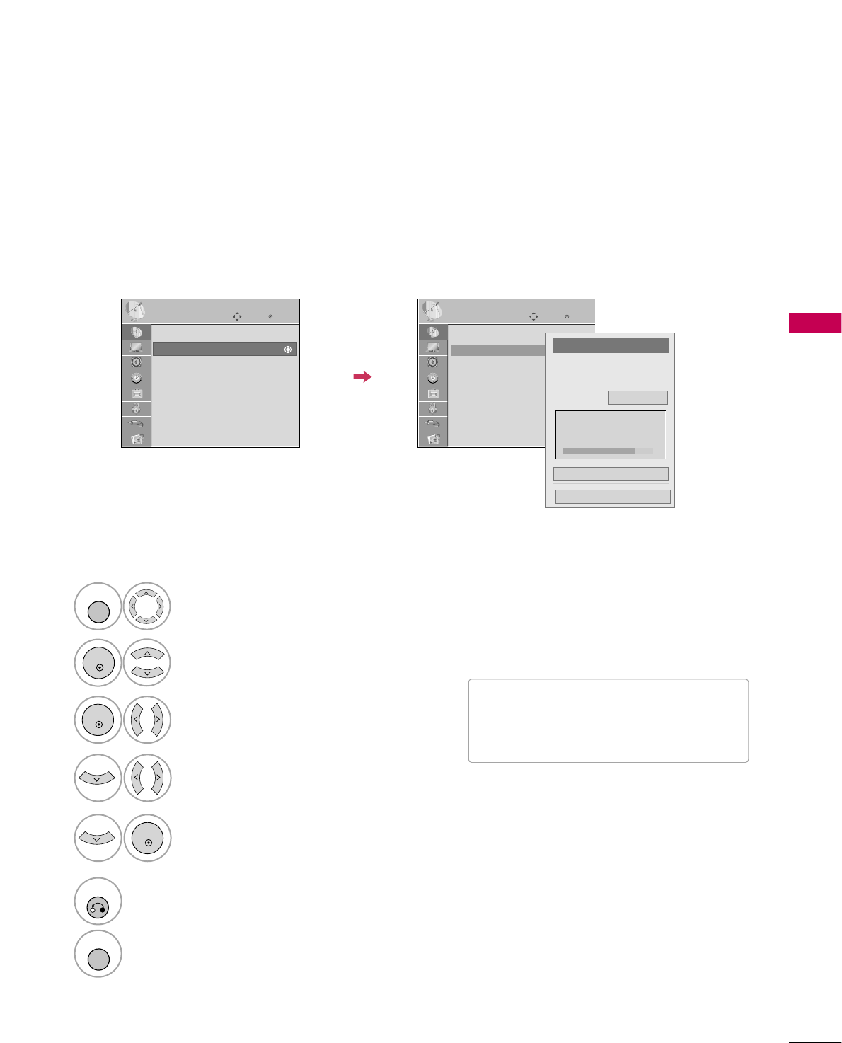
When you connect a USB device, this pop up menu is displayed automatically.
When the Pop Up menu does not appear, you can select Photo List or Music List or Extra contents.
On a USB device, you can not add a new folder or delete an existing folder.
or
ENTRY MODES
ENTER
■
Image shown may differ from your TV.
Enter
Move
USB
Select USB.
Select Eject.
1
MENU
3
2
ENTER
ENTER
4
RETURN
Return to the previous menu.
MENU
Return to TV viewing.
When removing the USB device
Photo List
Music List
Extra Contents
Eject
Enter
Move
USB
Photo List
Music List
Extra Contents
Eject
Close
Now you can eject USB.
i
Close
Choose the media you want.
Fl
i
Photo List
Music List
Extra Contents

USB
48
USB
Precautions with USB devices.
GOnly a USB storage device is recognizable.
GIf the USB storage device is connected through a USB hub, the device is not recognizable.
GA USB storage device using an automatic recognition program may not be recognized.
GA USB storage device which uses its own driver may not be recognized.
GThe recognition speed of a USB storage device may depend on each device.
GIn case of a card reader, up to four memory cards are concurrently recognizable.
GPlease do not turn off the TV or unplug the USB device when the connected USB storage device is working.
When such device is suddenly separated or unplugged, the stored files or the USB storage device may be dam-
aged.
GOnly use a USB storage device which has normal music, image or movie files.
GPlease connect power to a USB storage device (over 0.4A) which requires an external power supply. If not, the
device may not be recognized.
GPlease connect a USB storage device with cable is offered by USB maker. If connected with cable is not offered
by USB maker or an excessively long cable, the device may not be recognized.
GSome USB storage devices may not be supported or operate properly.
GFile alignment method of USB storage device is similar to Window XP and filename can recognize up to 100
English characters.
GPlease backup important files because data on the USB device may be damaged. Data management is the con-
sumer's responsibility and as a result, the manufacturer does not cover data damage.
G
Please use only a USB storage device which was formatted as a FAT32, NTFS file system provided with the Windows
operating system. In case of a storage device formatted as a different utility programme which is not supported by
Windows, it may not be recognized.
G
Data in a USB storage device cannot be deleted in the NTFS file system.
GIf your USB memory device has multiple partitions, or if you use a USB multi-card reader, you can use up to 4
partitions or USB memory devices.
G
The recommended capacity is 1TB or less for a USB external hard disk and 32GB or less for USB memory.
G
Any device with more than the recommended capacity may not work properly.
G
When using a USB HDD via the USB extensing cable, connect a support electric power source.
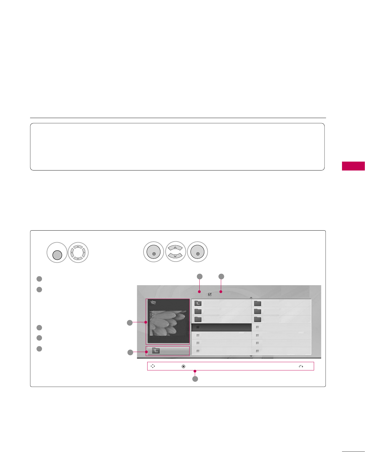
USB
49
PHOTO LIST
This TV only supports picture in JPEG(.jpg) format.
The On-Screen Display on your model may be slightly different.
Screen Components
Moves to upper level folder
Preview: Displays the
thumbnail/folder name of
the photo in the selected
folder
Current page/Total pages
Total number of marked photos
Corresponding buttons on
the remote control
Select USB.Select Photo List.
2
1
MENU
1
2
3
4
5
Navigation Popup Menu Exit
5
Page 2/3 No Marked
Photo List
Up Folder
1366x768, 125KB
KY101 06/10/2008
KY102 04/03/2008
JMJ001 01/01/2000
JMJ002 06/15/2008
JMJ003 04/03/2008
JMJ004 02/18/2008
KY103 03/30/2008
KY104 06/19/2008
KY105 01/31/2008
JMJ005 05/13/2008
JMJ006 05/26/2008
JMJ007 02/18/2008
JMJ008 02/18/2008
Up Folder
Drive1
JMJ001
3 4
2
1
Supported photo file: *.JPG
• You can view JPG files only.
• Only baseline scan is supported among JPG.
• Supported JPG size: 64 pixel (width) x 64 pixel (height) to 15360 pixel (width) x 8640 pixel (height)
ENTER
ENTER
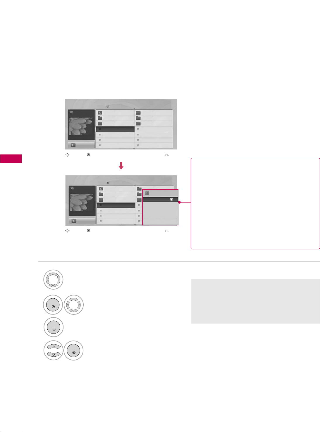
USB
50
USB
Photo Selection and Popup Menu
Select the target folder or drive.
Select the desired photos.
2
Show the Popup menu.
3
1
■When one or more photos are marked, you can
view individual photos or a slide show of the
marked photos. If no photos are marked, you
can view all photos individually or all photos in
the folder in a slide show.
4Select the desired Popup menu.
Page 2/3
No Marked
Photo List
Up Folder
1366x768, 125KB
KY101 06/10/2008
KY102 04/03/2008
JMJ001 01/01/2000
JMJ002 06/15/2008
JMJ003 04/03/2008
JMJ004 02/18/2008
KY103 03/30/2008
KY104 06/19/2008
KY105 01/31/2008
JMJ005 05/13/2008
JMJ006 05/26/2008
JMJ007 02/18/2008
JMJ008 02/18/2008
Up Folder
Page 2/3
No Marked
Photo List
Up Folder
1366x768, 125KB
KY101 06/10/2008
KY102 04/03/2008
JMJ001 01/01/2000
JMJ002 06/15/2008
JMJ003 04/03/2008
JMJ004 02/18/2008
KY103 03/30/2008
KY104 06/19/2008
KY105 01/31/2008
JMJ005 05/13/2008
JMJ006 05/26/2008
JMJ007 02/18/2008
JMJ008 02/18/2008
Up Folder
Drive1
Drive1
JMJ001
JMJ001 1366x768, 125KB
View
Mark
Mark All
Delete
Close
Navigation Exit
Popup Menu
Navigation Exit
Popup Menu
When you select a file (not folder), this PopUp
menu is displayed.
GView: Display the selected item.
GMark: Use to mark a photo.
GUnmark: Use to unmark a photo.
GMark All: Mark all photos on the screen.
GUnmark All: Deselect all marked photos.
GDelete or Delete Marked: Delete the selected
photo item.
GClose: Close the pop-up menu.
ENTER
ENTER
ENTER
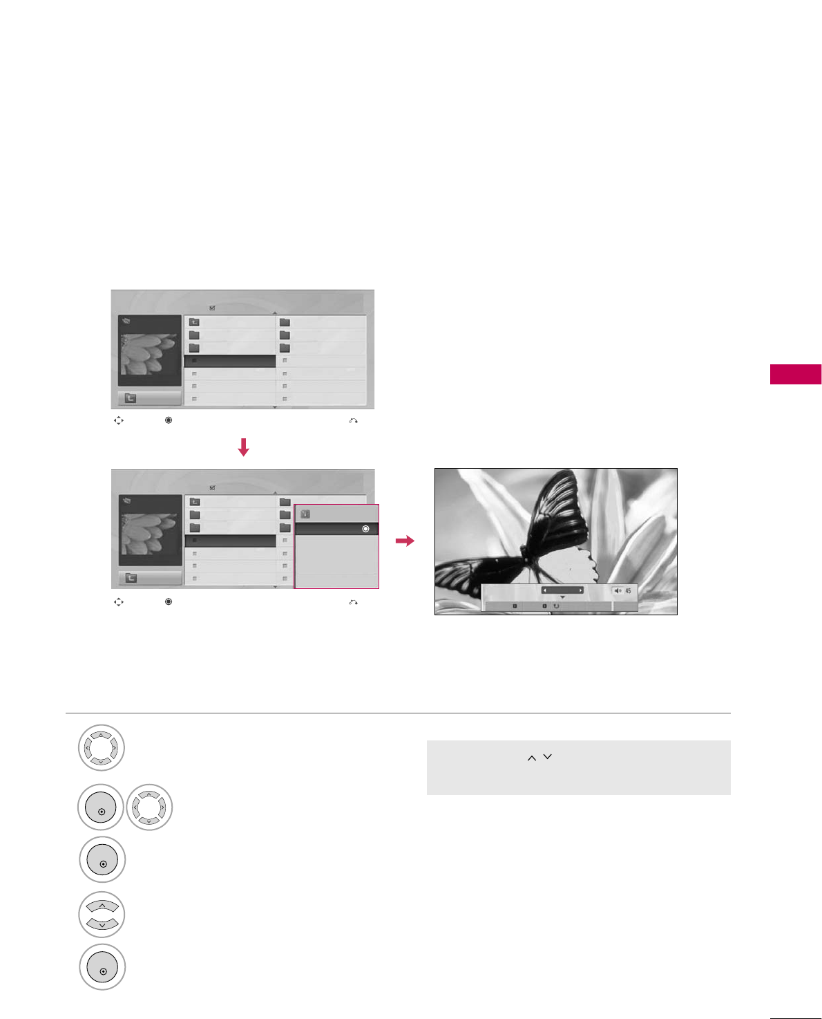
USB
51
Full Screen Menu
You can change the Photo List view so that it fills the screen. More operations are available in full
screen mode.
■Use the CH button to navigate in the
photo page.
Select the target folder or drive.
Select the desired photos.
Show the Popup menu.
5
Select View.
The selected photo is displayed in
full size.
2
3
1
4
Page 2/3
No Marked
Photo List
Up Folder
1366x768, 125KB
KY101 06/10/2008
KY102 04/03/2008
JMJ001 01/01/2000
JMJ002 06/15/2008
JMJ003 04/03/2008
JMJ004 02/18/2008
KY103 03/30/2008
KY104 06/19/2008
KY105 01/31/2008
JMJ005 05/13/2008
JMJ006 05/26/2008
JMJ007 02/18/2008
JMJ008 02/18/2008
Up Folder
Page 2/3
No Marked
Photo List
Up Folder
1366x768, 125KB
KY101 06/10/2008
KY102 04/03/2008
JMJ001 01/01/2000
JMJ002 06/15/2008
JMJ003 04/03/2008
JMJ004 02/18/2008
KY103 03/30/2008
KY104 06/19/2008
KY105 01/31/2008
JMJ005 05/13/2008
JMJ006 05/26/2008
JMJ007 02/18/2008
JMJ008 02/18/2008
Up Folder
Drive1
Drive1
JMJ001
JMJ001
Navigation Exit
Popup Menu
Navigation Exit
Popup Menu
The aspect ratio of a photo may change the size of the
photo displayed on the screen in full size.
Press the RETURN button to move to the previous menu
screen.
1/17
Slideshow BGM Delete Option Hide
1366x768, 125KB
View
Mark
Mark All
Delete
Close
ENTER
ENTER
ENTER
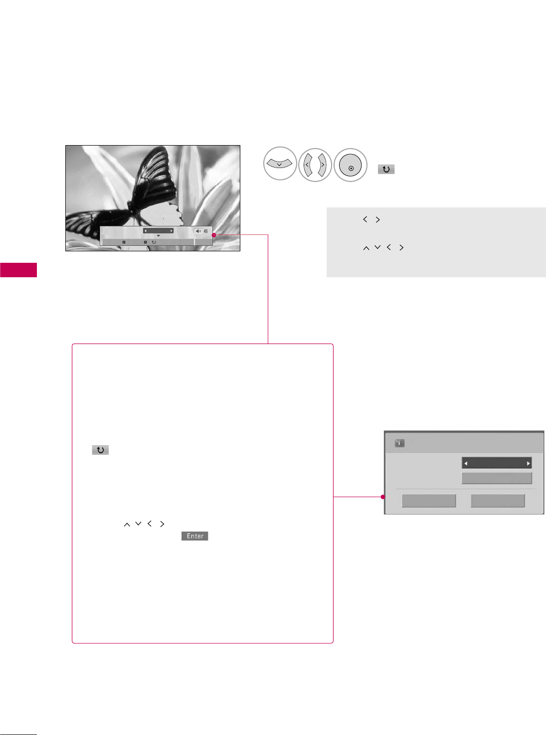
USB
52
USB
Press F G to set the time interval between slides.
Slide Speed Fast
Cancel
...
Music Album
Enter
Select the Slideshow, BGM,
(Rotate), Delete,Option,
or Hide.
■Use button to select the previous or
next photo.
■Use button to select and control
the menu on the full-sized screen.
6
1/17
Slideshow BGM Delete Option Hide
GSlideshow: Selected photos are displayed during the
slide show. If no photo is selected, all photos in the cur-
rent folder are displayed during slide show.
■Set the time interval of the slide show in Option.
GBGM: Listen to music while viewing photos in full size.
■Set the BGM device and album in Option.
G(Rotate): Rotate photos.
■Rotates the photo 90°, 18 0 °, 270°, 360°clockwise.
GDelete: Delete photos.
GOption: Set values for Slide Speed and Music
Album.
■Use button and ENTER button to set
values. Then go to and press ENTER to save
the settings.
■You cannot change Music Album while BGM is
playing.
GHide : Hide the menu on the full-sized screen.
■To see the menu again on the full-sized screen, press
ENTER button to display.
ENTER
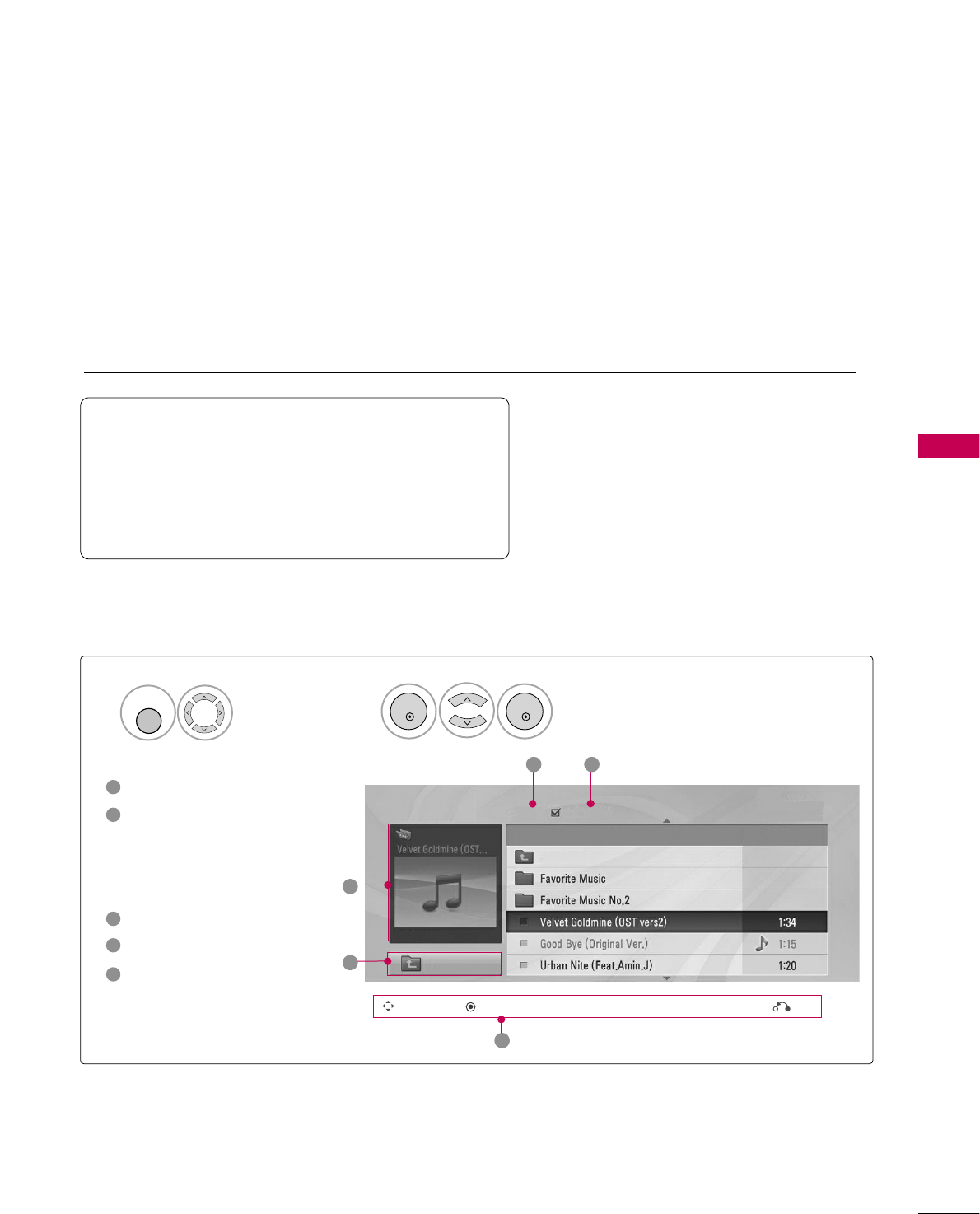
USB
53
MUSIC LIST
You can use the Music List menu to play MP3 files from a USB storage device.
This TV cannot play back copy-protected files.
The On-Screen Display on your model may be slightly different.
Screen Components
Moves to upper level folder
Preview: If a supported pic-
ture of the album jacket is
in the file, it will be dis-
played here.
Current page/Total pages
Total number of marked files
Corresponding buttons on
the remote control
1
3
4
5
2
Select USB.Select Music List.
12
MENU
Music List
Up Folder
Title Duration
3 4
2
1
Page 2/3 No Marked
Drive1
Navigation Popup Menu Exit
5
A 00:00 / 04:16
Up Folder
Supported music file: *.MP3
Bit rate range 32 Kbps - 320 Kbps
• Sampling rate (Sampling Frequency)
MPEG1 layer 3: 32 kHz, 44.1 kHz, 48 kHz
MPEG2 layer 3: 16 kHz, 22.05 kHz, 24 kHz
MPEG2.5 layer 3: 8 kHz, 11.025 kHz, 12 kHz
ENTER
ENTER
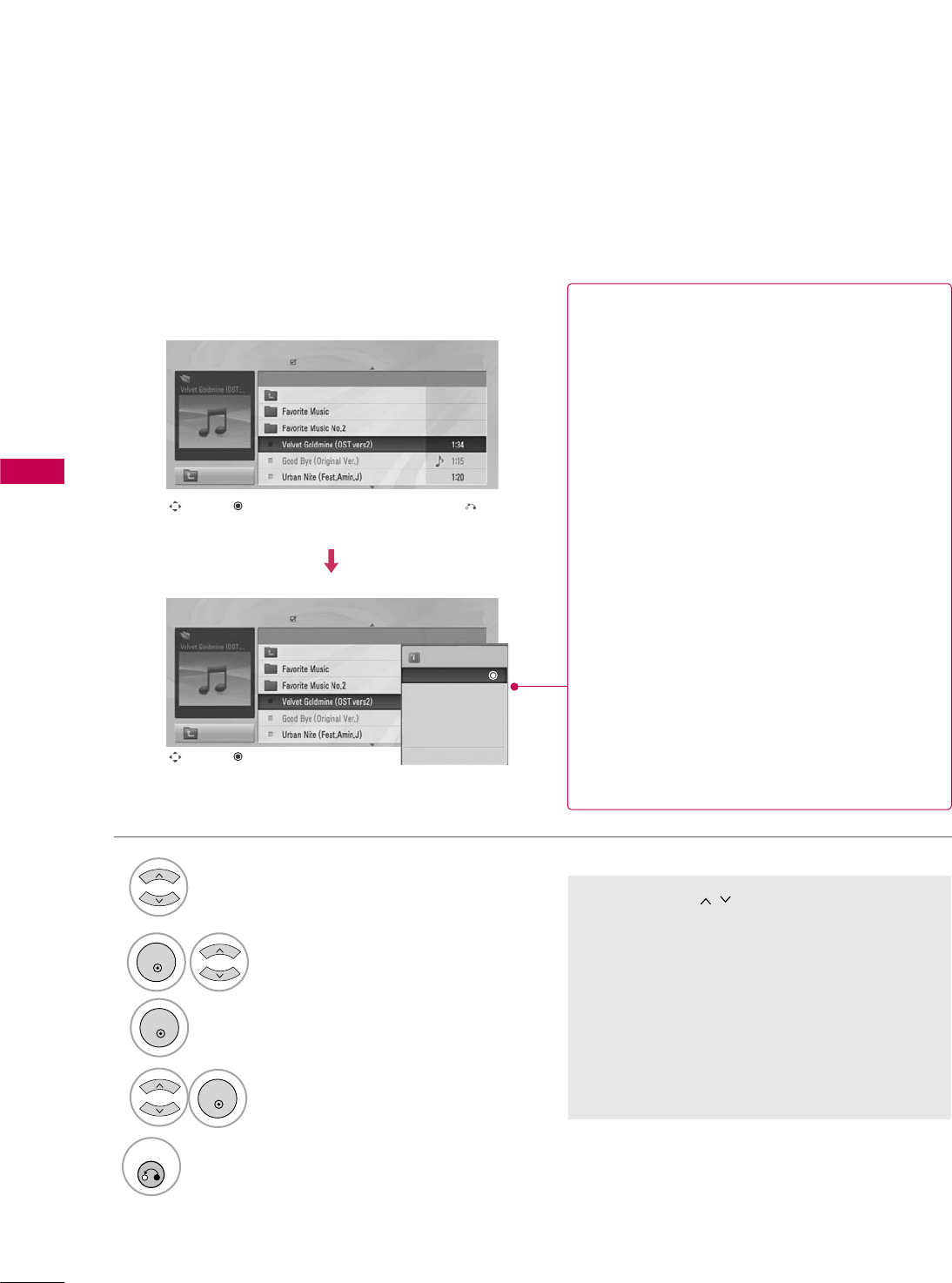
USB
54
USB
Music Selection and Popup Menu
■Use the CH button to navigate in the
music page.
■If no music is marked, all the music in the fold-
er will be played in sequence. When one or
more music files are marked, the marked music
files will be played in sequence. If you want to
listen to only one song repeatedly, just mark
that one file and play.
Select the target folder or drive.
Select the desired musics.
Show the Popup menu.
Select the desired Popup menu.
2
3
1
4
5
RETURN
Return to TV viewing.
Navigation Exit
Popup Menu
Navigation Popup Menu
Page 2/3
No Marked
Music List
Up Folder
A 00:00 / 04:16
Up Folder
Drive1 Title
Duration
Page 2/3
No Marked
Music List
Up Folder
A 00:00 / 04:16
Up Folder
Drive1 Title
Duration
3945 KB
128 Kbps
Play
Play with Photo
Mark
Mark All
Delete
Close
GPlay (During stop): Play the selected file.
Once a song finishes playing, the next selected
one will be played. When there are no selected
files to play, the next one in the current folder
will be played. If you go to a different folder and
press the ENTER button, the current song in
playback will stop.
GPlay Marked: Play the selected files. Once a
file finishes playing, the next selected one will
be played automatically.
GStop Play (During playback): Stop the play-
ing files.
GPlay with Photo: Start playing the selected
files and then move to the Photo List.
GMark: Use to mark a file.
GUnmark: Use to unmark a file.
GMark All: Mark all files in the folder.
GUnmark All: Deselect all marked files.
GDelete or Delete Marked: Delete the selected
files.
GClose: Close the pop-up menu.
ENTER
ENTER
ENTER
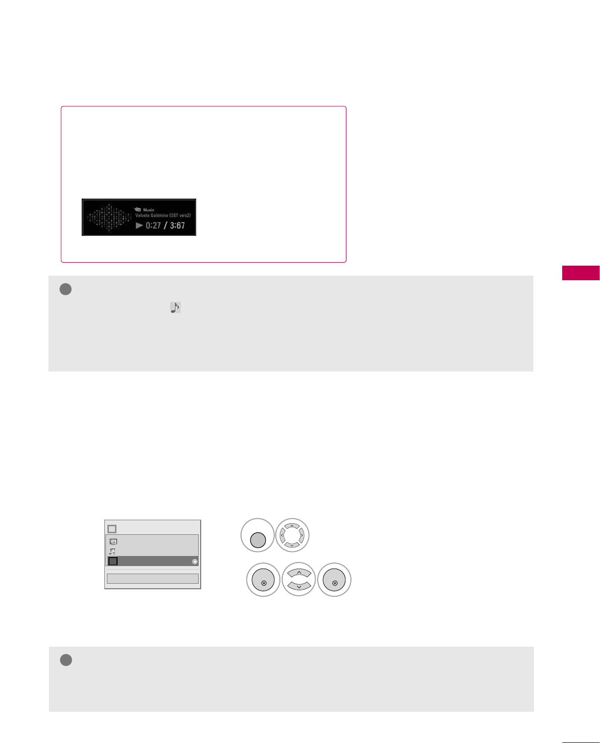
USB
55
■The play information box (as shown below) will automatically
move across the screen when there is no user input to pre-
vent a fixed image remaining on the screen for a extended
period of time.
NOTE
!
GWhen music is playing, is displayed in front of the music play time.
GA damaged or corrupted music file that does not play displays 00:00 as the play time.
GFiles downloaded from a paid service with copyright protection are not supported and will not play.
GPress ENTER, Aor RETURN button to stop the screen saver.
EXTRA CONTENTS
Extra Contents will be activated when Data Channel service is available.
Select US B.
Select Extra Contents.
1
2
MENU
ENTER
ENTER
NOTE
!
GPro:Centric contents in USB memory stick can be played.
GFor more information. contact to Customer Support.(www.lgcommercial.com)
Close
Choose the media you want.
Fl
i
Photo List
Music List
Extra Contents
PICTURE CONTROL
56
PICTURE CONTROL
PIP (PICTURE-IN-PICTURE)
PIP enables the end user to view two sources on the screen at the same time. The end user can switch
between the Main and Sub picture sizes.
789
0
PQRS TUV WXYZ
PIP CH- PIP CH+ PIP SWAP PIP INPUT
PIP SAP
FLASHBK
TIMER
&@
RATIO
PIP INPUT
Selects viewing source for PIP
window.
PIP SWAP
Switches Main screen and
PIP window sources.
PIP CH+
Selects next higher channel
for PIP window.
PIP CH-
Selects next lower channel
for PIP window.
PIP Operation
1. Connect auxiliary source(s) to TV
connections panel.
2. Enter Installer menu to be sure
source(s) is enabled.
3. Use the interactive remote provided
in the room to operate PIP.
4. Press PIP on remote.
Use the PIP function keys to
operate the available PIP features.
5. To exit PIP mode, simply press PIP.
PIP
Turns PIP mode on and off.
■Note: Actual size of Main screen and PIP inset may be different than
shown above.
PICTURE CONTROL
57
AV1, AV2, HDMI1, HDMI2
TV
TV, AV1or AV2, HDMI1, HDMI2
AV1or AV2
Main Picture Source Available Sub Picture Sources
HDMI1or HDMI2
Component, RGB-PC
TV, AV1, AV2, HDMI1or HDMI2
TV, AV1, AV2, HDMI1, HDMI2
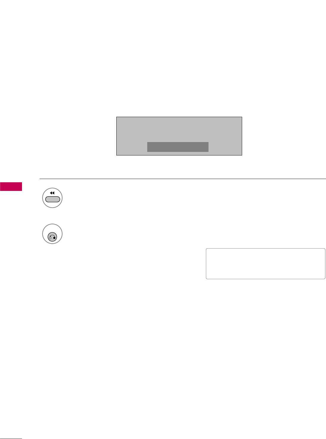
PICTURE CONTROL
58
PICTURE CONTROL
PICTURE SIZE (ASPECT RATIO) CONTROL
This feature lets you choose the way an analog picture with a 4:3 aspect ratio is displayed on your TV.
■ RGB-PC input source can only use 4:3 or 16:9 aspect ratio.
Press the RATIO button repeatedly to select the picture options
: Set By Program, 4:3, 16:9, Zoom, Just Scan.
1
RATIO
2
RETURN
Return to TV viewing.
116:9
■ You can also adjust Aspect Ratio in
the PICTURE menu.
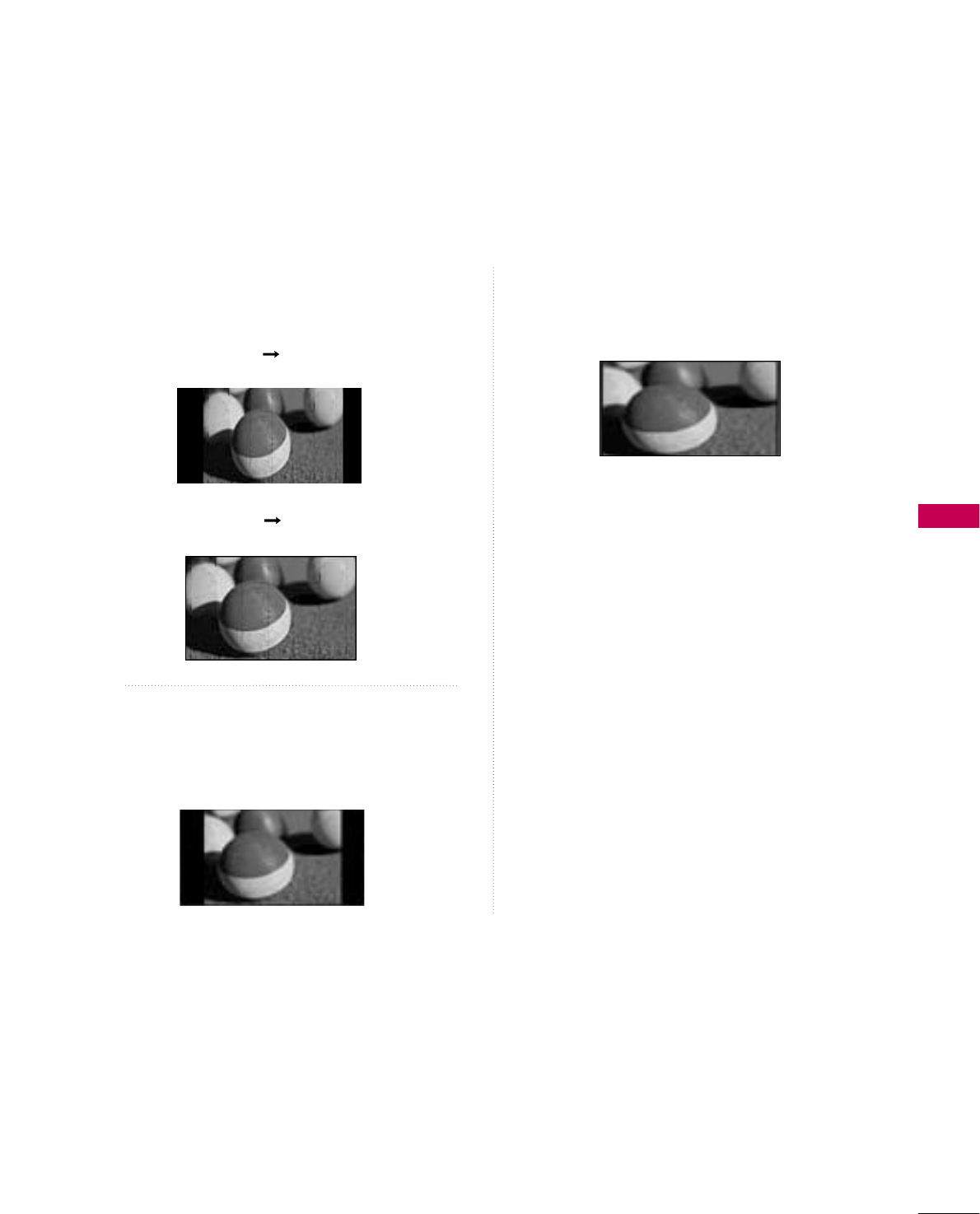
PICTURE CONTROL
59
Set by program
Selects the proper picture proportion to match
the source’s image.
4:3
Choose 4:3 when you want to view a picture
with an original 4:3 aspect ratio.
16:9
Adjust the picture horizontally, in a linear pro-
portion to fill the entire screen.
(4:3 4:3)
(16:9 16:9)
Set By Program
Set By Program
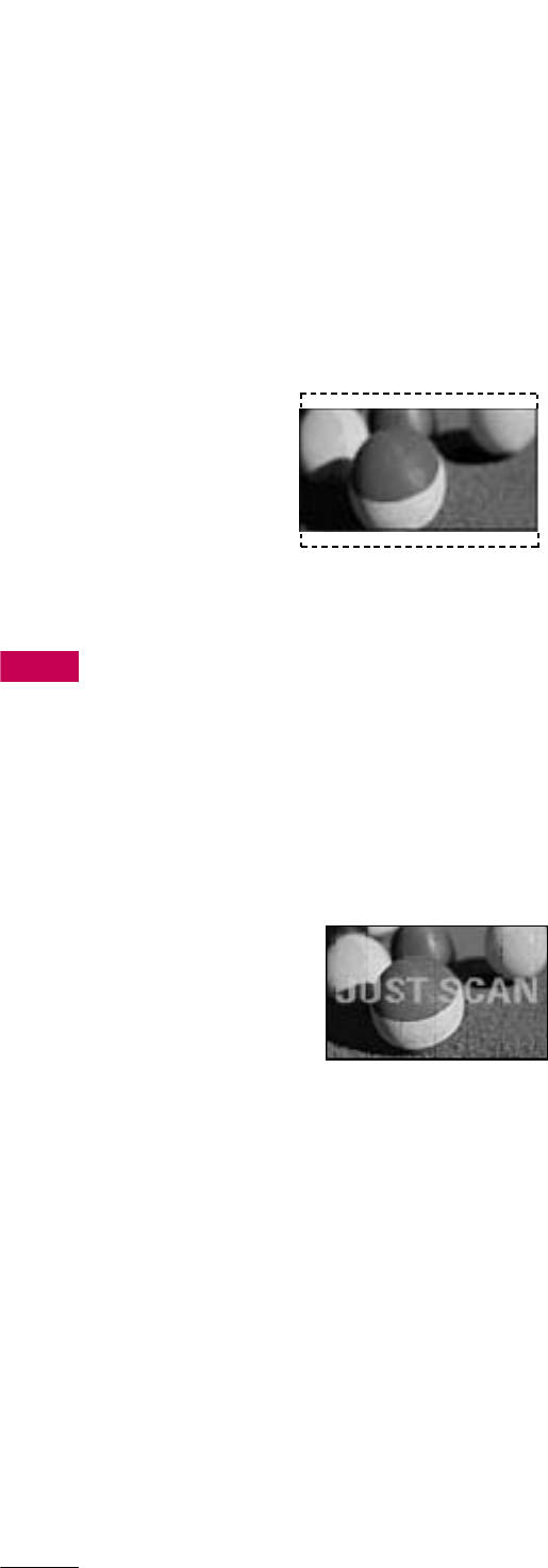
PICTURE CONTROL
60
PICTURE CONTROL
Zoom
Choose Zoom when you want to view the picture
without any alteration. However, the top and
bottom portions of the picture will be cropped.
Just Scan
Normally the edges of video signals are cropped
1-2%. Just Scan turns off this cropping and
shows the complete video.
Notes: If there is noise on the edges of the original
signal, it will be visible when Just Scan is activated.
Just Scan operates only with
DTV/CADTV/HDMI-DTV/DVI-DTV
(720p/1080i), Component(720p/1080i) input
sources.
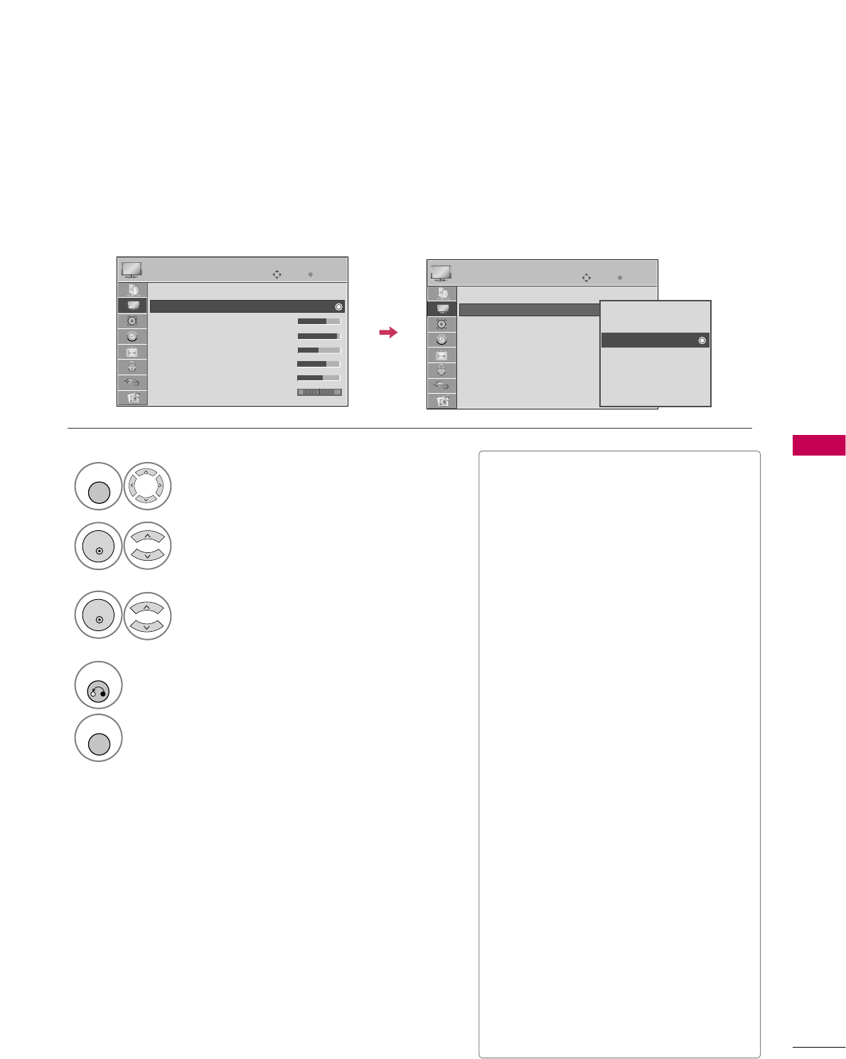
PICTURE CONTROL
61
Enter
Move
PICTURE
E
Aspect Ratio : 16:9
Picture Mode : Standard
• Backlight 70
• Contrast 90
• Brightness 50
• Sharpness 70
• Color 60
• Tint 0
PRESET PICTURE SETTINGS (PICTURE MODE)
There are factory presets for picture settings available in the user menus. You can use a preset, change each
setting manually, , or use the Intelligent Sensor.
Select PICTURE.
Select Intelligent Sensor, Vivid,
Standard, Natural, Cinema, Sport or
Game.
1
MENU
3
ENTER
Select Picture Mode.
2
ENTER
4
RETURN
Return to the previous menu.
MENU
Return to TV viewing.
Enter
Move
PICTURE
E
Aspect Ratio : 16:9
Picture Mode : Standard
• Backlight 70
• Contrast 90
• Brightness 50
• Sharpness 70
• Color 60
• Tint 0
■When selecting Intelligent Sensor is
changed to Auto automatically.
■When selecting Intelligent Sensor, it
is changed contrast, brightness, sharp-
ness, color and tint automatically.
■Vivid, Standard, Natural, Cinema,
Sport, and Game Settings are preset
for the optimum picture quality at the
factory.
■Intelligent Sensor: The most suitable
picture is automatically adjusted accord-
ing to the surrounding conditions.
■Vivid: This is the mode to maximize the
effect of the video in the retail store.
Strengthen the contrast, brightness,
color and sharpness for vivid picture.
■Standard: This is the mode to realize
optimum viewing condition for the gen-
eral user.
■Natural: This is the mode to display the
most natural screen status.
■Cinema: This mode optimizes video for
watching movies.
■Sport: This is the video mode to
emphasize dynamic video and primary
color (e.g, white, uniform, grass, sky blue
etc.) by realizing the optimal screen for
sports.
■Game: This is the mode to realize fast
response speed in a fast gaming screen.
RG RG
Intelligent Sensor
Vivid
Standard
Natural
Cinema
Sport
Game
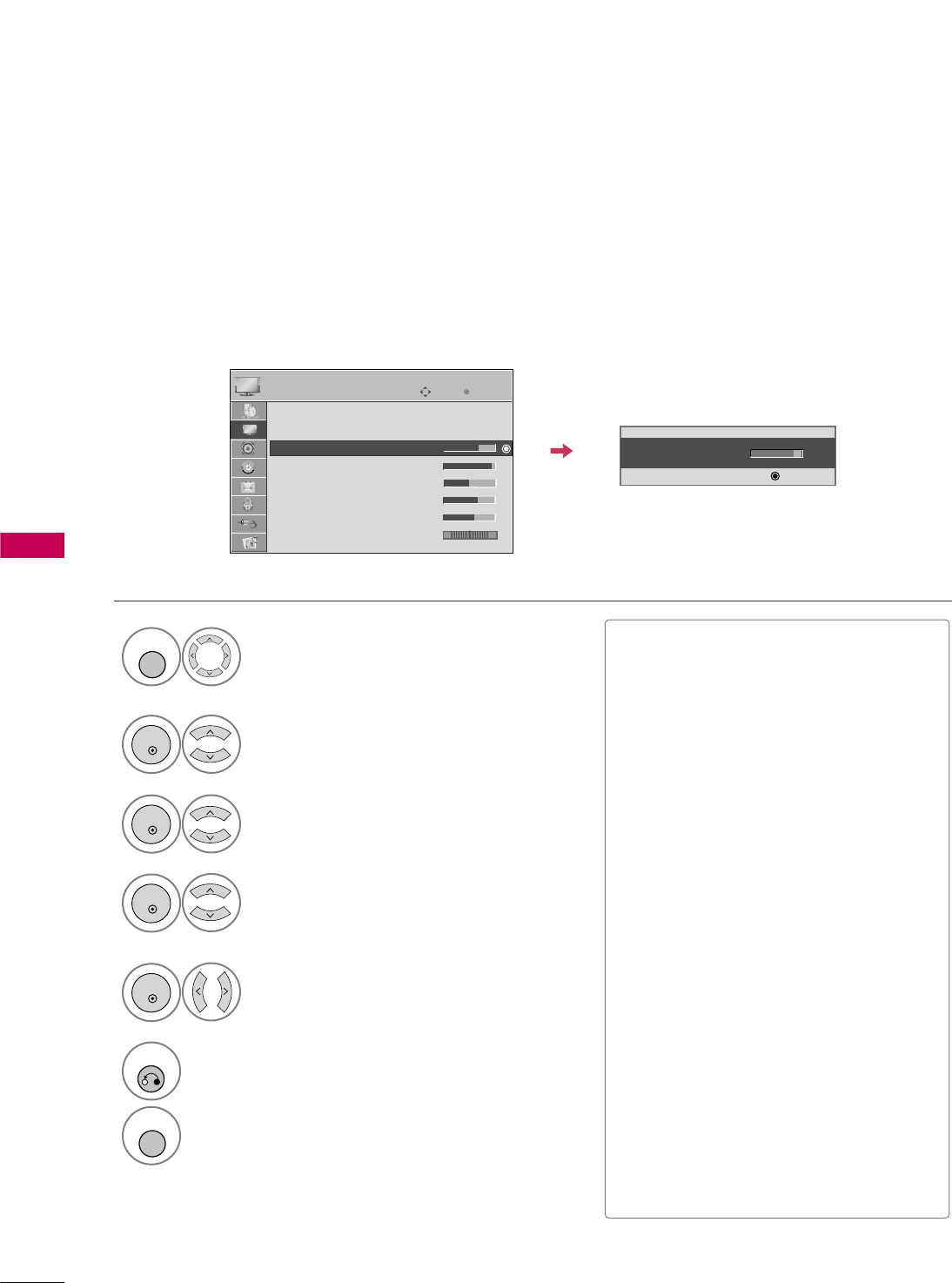
PICTURE CONTROL
62
PICTURE CONTROL
MANUAL PICTURE ADJUSTMENT - USER MODE
Adjust the picture appearance to suit your preference and viewing situations.
This feature is disable in “Picture Mode-Intelligent Sensor”.
Select PICTURE.
Make appropriate adjustments.
Select Backlight, Contrast,
Brightness, Sharpness, Color,
or Tint.
1
MENU
Select Picture Mode.
2
ENTER
Select Vivid,Standard, Natural,
Cinema, Sport or Game.
3
ENTER
4
ENTER
5
ENTER
6
RETURN
Return to the previous menu.
Return to TV viewing.
• Back Light 70
EE
E
E
E
Enter
MENU
Enter
Move
PICTURE
E
Aspect Ratio : 16:9
Picture Mode : Standard
• Backlight 70
• Contrast 90
• Brightness 50
• Sharpness 70
• Color 60
• Tint 0
■Backlight: This function adjusts the
brightness of LCD panel, to control the
brightness of the screen. Adjusting the
backlight is recommended when setting
the brightness of the set. When decreas-
ing the backlight, the brightness of the
black becomes darker without any loss in
video signal and the power consumption
is reduced.
■Contrast: Increase or decrease the gra-
dient of the video signal. You may use
Contrast when the bright part of picture
is saturated.
■Brightness: Adjusts the base level of
the signal in the picture. You may use
Brightness when the dark part of the pic-
ture is saturated.
■Sharpness: Adjusts the level of crisp-
ness in the edges between the light and
dark areas of the picture. The lower the
level, the softer the image.
■Color: Adjusts intensity of all colors.
■Tint: Adjusts the balance between red
and green levels.
RG
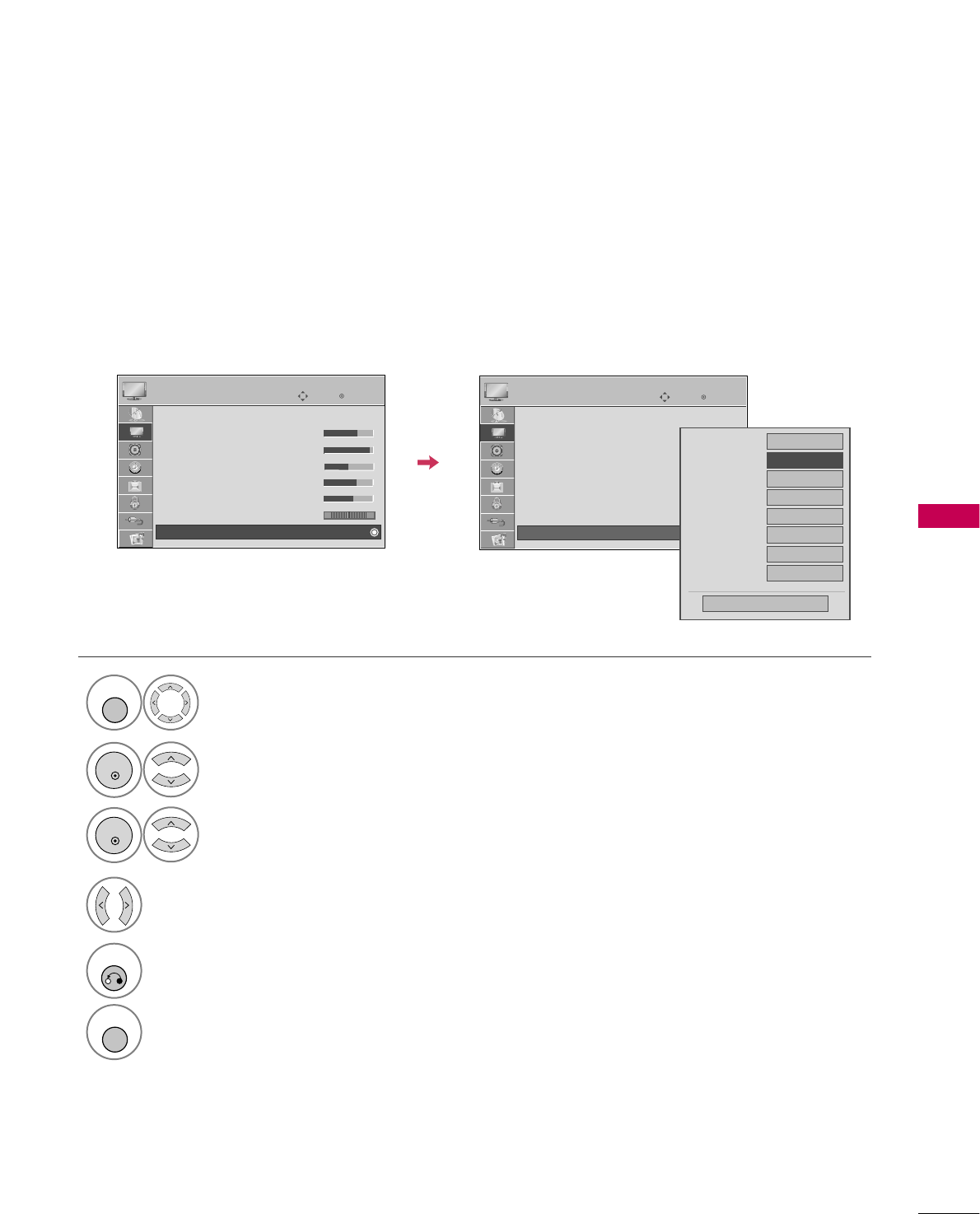
PICTURE CONTROL
63
PICTURE IMPROVEMENT TECHNOLOGY
You can calibrate the screen for each Picture Mode or set the video value according to the special video screen.
You can set the video seeing differently for each input.
To reset to the factory default after making adjustments to each input source, execute the Picture Reset
function for each Picture Mode.
Select PICTURE.
Select Advanced Control.
Select your desired options.
1
MENU
3
2
ENTER
ENTER
5
RETURN
Return to the previous menu.
Return to TV viewing.
Make appropriate adjustments.
4
MENU
Enter
Move
PICTURE
E
Enter
Move
PICTURE
E
Picture Mode : Standard
• Backlight 70
• Contrast 90
• Brightness 50
• Sharpness 70
• Color 60
• Tint 0
• Advanced Control
RG
Color Temperature
Medium
Dynamic Contrast
FMedium G
Dynamic Color
Low
Noise Reduction
Medium
Gamma
Medium
Black Level
Low
Eye Care
Off
Close
Real Cinema
Off
E
RG
Picture Mode : Standard
• Backlight 70
• Contrast 90
• Brightness 50
• Sharpness 70
• Color 60
• Tint 0
• Advanced Control
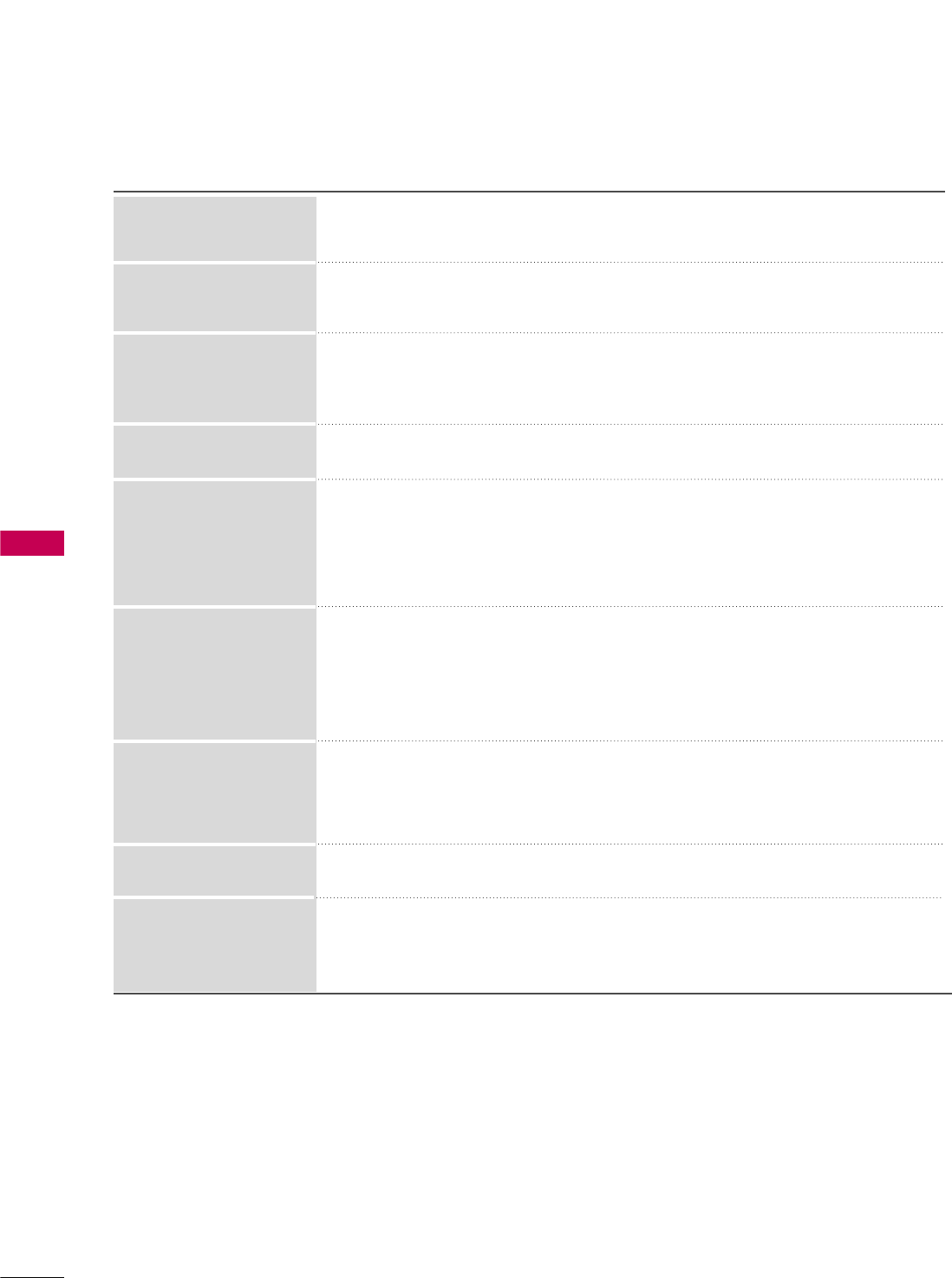
PICTURE CONTROL
64
PICTURE CONTROL
■Set to warm to enhance hotter colors such as red, or set to cool to enhance cooler
colors such as blue.
■Adjusts the contrast to keep it at the best level according to the brightness of the
screen. The picture is improved by making bright parts brighter and dark parts darker.
■Adjusts screen colors so that they look livelier, richer and clearer. This feature
enhances hue, saturation and luminance so that red, blue, green and white look
more vivid.
■Reduces screen noise without compromising video quality.
Low : Make dark and middle gray level area of the picture brighter.
Medium: Express original picture levels.
High: Make dark and middle gray level area of the picture darker.
■You can adjust brightness of dark area and middle gray level area of the picture.
Low: The reflection of the screen gets darker.
High: The reflection of the screen gets brighter.
■Set black level of the screen to proper level.
■This function enables to select 'Low' or 'High' in the following mode: AV (NTSC-M),
HDMI or Component.
■Adjust the brightness of the screen to prevent the screen from being too bright.
Dims extremely bright pictures.
■This feature is disabled in “Picture Mode-Intelligent Sensor, Vivid, Cinema”.
■Makes video clips recorded in film look more natural by eliminating judder effect.
Dynamic Contrast
Dynamic Color
Noise Reduction
Gamma
Black Level
Eye Care
Real Cinema
Color Temperature
Standard: Displays standard set of colors.
Wide: Increase number of colors used.
■Maximize the utilization of color to increase color quality.
Color Gamut
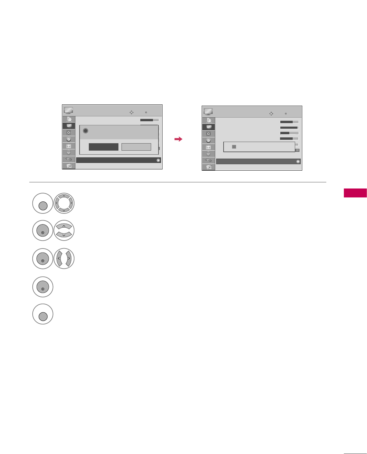
PICTURE CONTROL
65
PICTURE RESET
Settings of the selected picture modes return to the default factory settings.
Enter
Move
PICTURE
E
Enter
Move
PICTURE
• Backlight 70
• Contrast 90
• Brightness 50
• Sharpness 70
• Color 60
• Tint 0
• Advanced Control
• Picture Reset
Screen (RGB-PC)
E
Select PICTURE.
Select Picture Reset.
Initialize the adjusted value.
1
MENU
2
ENTER
Select Yes.
3
ENTER
5
MENU
Return to TV viewing.
4
ENTER
• Backlight 70
• Contrast 90
• Brightness 50
• Sharpness 70
• Color 60
• Tint 0
• Advanced Control
• Picture Reset
Screen (RGB-PC)
RG
No
Yes
All picture settings will be resetted.
Continue?
?
RG
Resetting video configuration...
ii
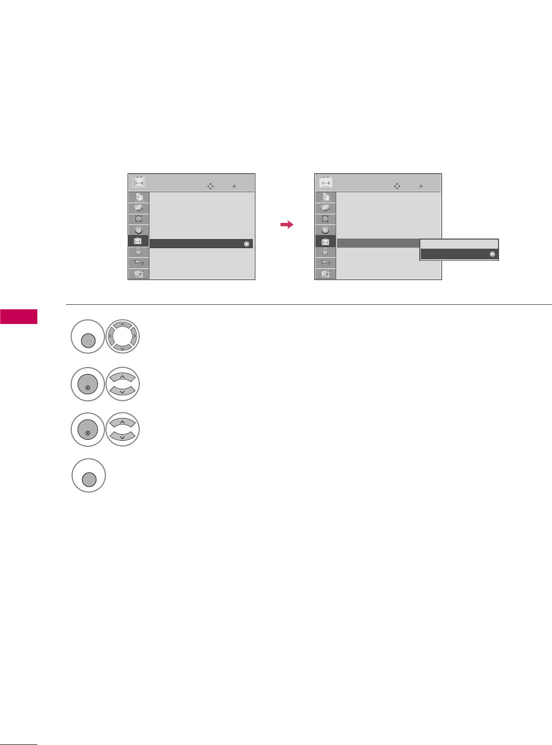
PICTURE CONTROL
66
PICTURE CONTROL
DEMO MODE
Select OPTION.
Select Demo Mode.
1
MENU
2
ENTER
Select O n to show the various
feature of the TV.
3
ENTER
4
MENU
Return to TV viewing.
After a while, Demo Mode starts.
If you want to stop the demo, press any button
(Except VOL +, - and MUTE button).
Enter
Move
OPTION
Menu Language : English
Audio Language : English
Caption : Off
Set ID : 1
Demo Mode : Off
Data Broadcasting
Enter
Move
OPTION
Menu Language : English
Audio Language : English
Caption : Off
Set ID : 1
Demo Mode : Off
Data Broadcasting
Off
On
Displays a slide show to explain the various feature of this TV.
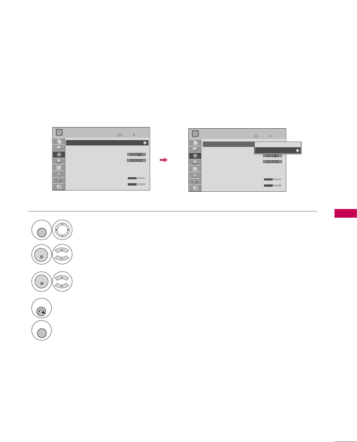
SOUND & LANGUAGE CONTROL
67
SOUND & LANGUAGE CONTROL
AUTO VOLUME LEVELER (AUTO VOLUME)
Auto Volume makes sure that the volume level remains consistent whether you are watching a commercial or a
regular TV program.
Because each broadcasting station has its own signal conditions, volume adjustment may be needed every
time the channel is changed. This feature allows users to enjoy stable volume levels by making automatic
adjustments for each program.
Select AUDIO.
Select Auto Volume.
Select O n or O ff.
1
MENU
3
2
ENTER
ENTER
4
RETURN
Return to the previous menu.
MENU
Return to TV viewing.
Enter
Move
AUDIO
E
LR
-+
Enter
Move
AUDIO
E
LR
-+
Auto Volume : On
Clear Voice II : On
• Level 3
Balance 0
Sound Mode : Standard
•
SRS TruSurround XT:
Off
• Treble 50
• Bass 50
Auto Volume : Off
Clear Voice II : On
• Level 3
Balance 0
Sound Mode : Standard
•
SRS TruSurround XT:
Off
• Treble 50
• Bass 50
Off
On
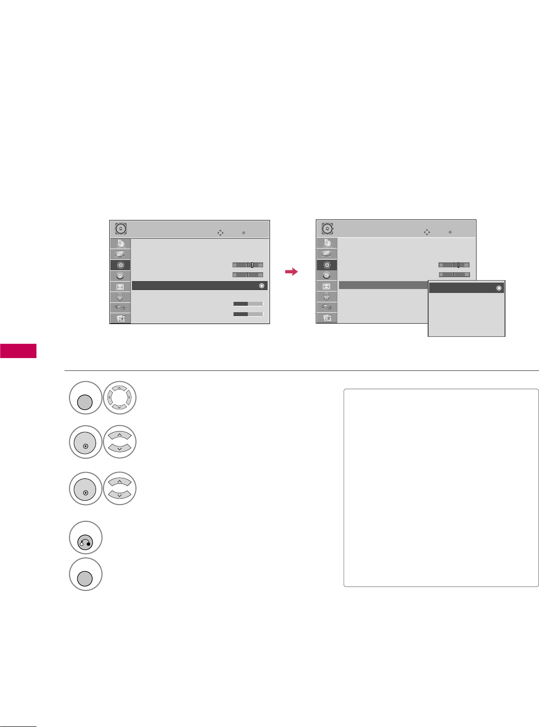
SOUND & LANGUAGE CONTROL
68
SOUND &LANGUAGE CONTROL
PRESET SOUND SETTINGS (SOUND MODE)
Sound Mode lets you enjoy the best sound without any special adjustment as the TV sets the appropriate
sound options based on the program content.
SOUND &LANGUAGE CONTROL
Select AUDIO.
Select Sound Mode.
1
MENU
2
ENTER
Select Standard, Music,
Cinema, Sport, or Game.
3
ENTER
4
RETURN
Return to the previous menu.
MENU
Return to TV viewing.
Enter
Move
AUDIO
E
LR
Enter
Move
AUDIO
E
LR
Auto Volume : Off
Clear Voice II : Off
• Level 3
Balance 0
Sound Mode : Standard
•
SRS TruSurround XT:
Off
• Treble 50
• Bass 50
Auto Volume : Off
Clear Voice II : Off
• Level 3
Balance 0
Sound Mode : Standard
•
SRS TruSurround XT:
Off
• Treble 50
• Bass 50
Standard
Music
Cinema
Sport
Game
-+ -+
■Standard, Music, Cinema, Sport,
and Ga me are preset for optimum
sound quality at the factory.
■St an da rd: Offers standard-quality
sound.
■Music: Optimizes sound for listening to
music.
■Cinema: Optimizes sound for watching
movies.
■Sport: Optimizes sound for watching
sports events.
■Game: Optimizes sound for playing
games.
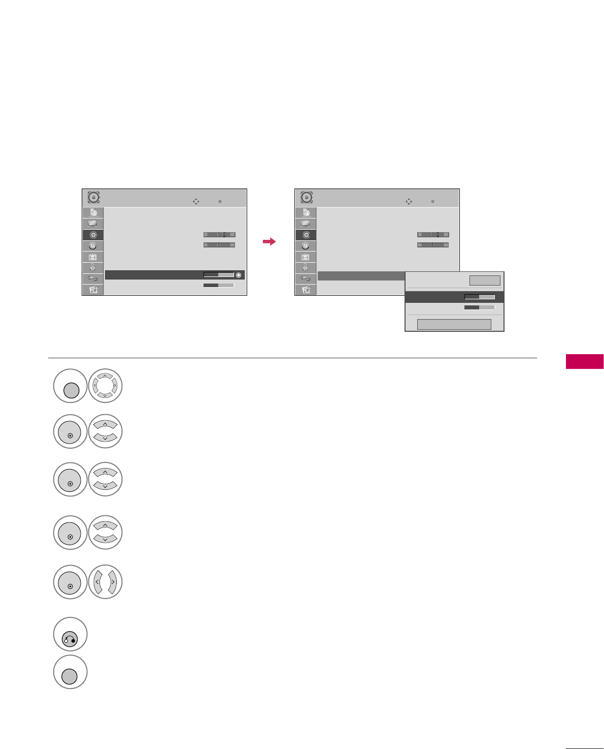
SOUND & LANGUAGE CONTROL
69
SOUND SETTING ADJUSTMENT - USER MODE
Adjust the sound to suit your taste and room situations.
Select AUDIO.
Select Sound Mode.
Select Treble or Bass.
1
MENU
4
2
ENTER
Select Standard, Music,
Cinema, Sport, or Game.
3
ENTER
ENTER
Make appropriate adjustments.
5
ENTER
6
RETURN
Return to the previous menu.
MENU
Return to TV viewing.
Enter
Move
AUDIO
LR
E
Auto Volume : Off
Clear Voice II : Off
• Level 3
Balance 0
Sound Mode : Standard
•
SRS TruSurround XT:
Off
• Treble 50
• Bass 50
Enter
Move
AUDIO
LR
E
Auto Volume : Off
Clear Voice II : Off
• Level 3
Balance 0
Sound Mode : Standard
•
SRS TruSurround XT:
Off
• Treble 50
• Bass 50
Close
E
E
• Treble 50
• Bass 50
•
SRS TruSurround XT
Off
-+ -+
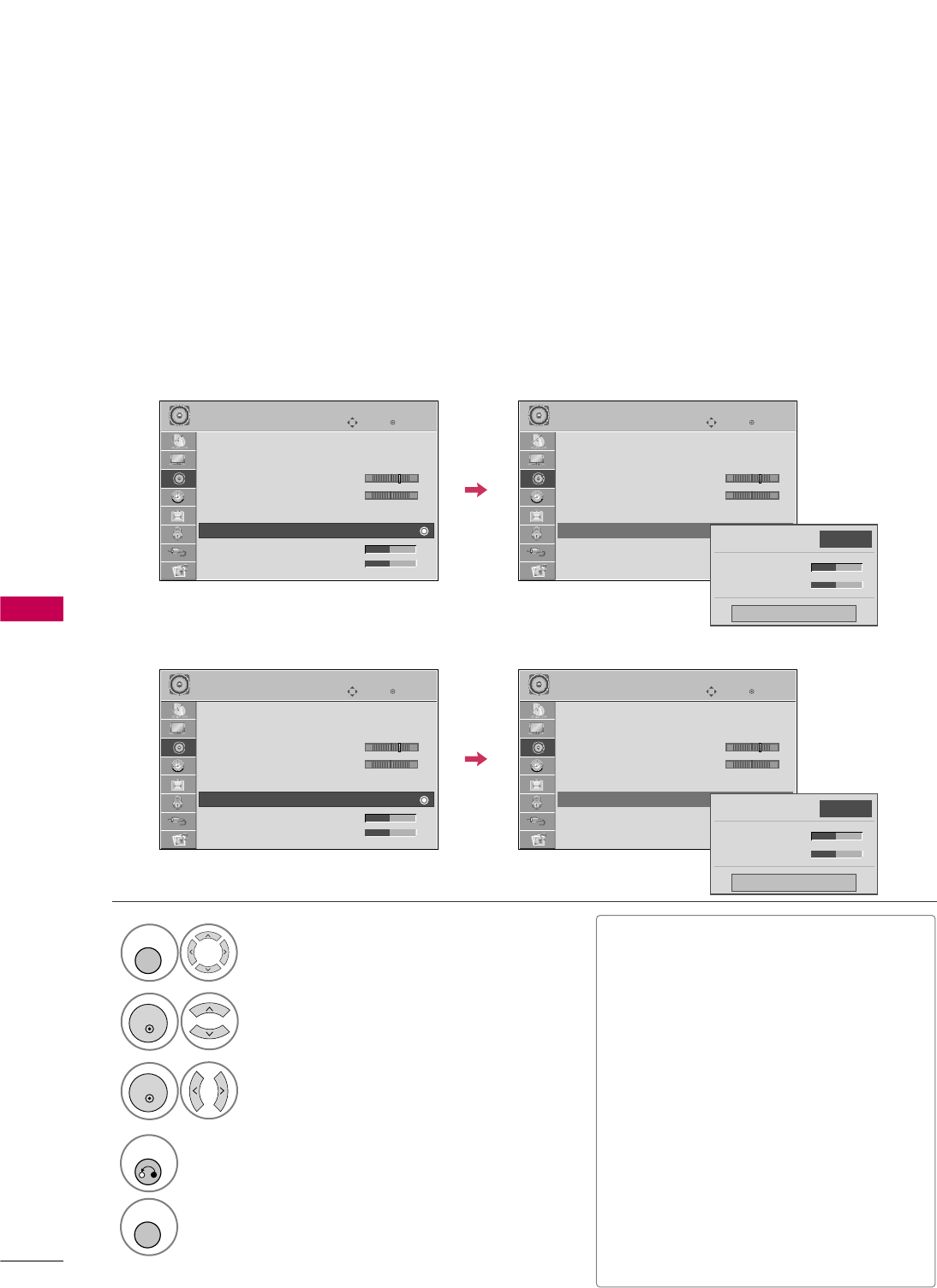
SOUND & LANGUAGE CONTROL
70
SOUND &LANGUAGE CONTROL
SRS TRUSURROUND XT / INFINITE SOUND
Select AUDIO.
Select SRS TruSurround XT
or Infinite Sound.
Select O n or Off.
1
MENU
3
2
ENTER
ENTER
4
RETURN
Return to the previous menu.
MENU
Return to TV viewing.
Takes advantage of any multi-channel format without needing to add extra speakers or equipment. Dialog
clarity, bass enrichment, and the addition of stereo audio enhancement produces an immersive sound experi-
ence from standard stereo material.
■If sound quality or volume is not at the
level you want, it is recommended to use a
separate home theater system or amp to
cope with different user environments.
■If you select “Clear Voice II-On”, SRS
TruSurround XT feature will not work.
■SRS TruSurround XT: TruSurround XT
is a patented SRS technology that solves
the problem of playing 5.1 multichannel
content over two speakers.
■Infinite Sound: Infinite Sound is a
patented LG proprietary sound process-
ing technology that strives immersive 5.1
surround sound with just two front speak-
ers. (For 32/37/42/47/55LD650H)
Enter
Move
AUDIO
LR
E
Auto Volume : Off
Clear Voice II : Off
• Level 3
Balance 0
Sound Mode : Standard
•
SRS TruSurround XT:
Off
• Treble 50
• Bass 50
Enter
Move
AUDIO
LR
E
Auto Volume : Off
Clear Voice II : Off
• Level 3
Balance 0
Sound Mode : Standard
•
SRS TruSurround XT:
Off
• Treble 50
• Bass 50
Close
• Treble 50
• Bass 50
•
SRS TruSurround XT
Off
-+ -+
Enter
Move
AUDIO
LR
E
Auto Volume : Off
Clear Voice II : Off
• Level 3
Balance 0
Sound Mode : Standard
•
Infinite Sound:
Off
• Treble 50
• Bass 50
Enter
Move
AUDIO
LR
E
Auto Volume : Off
Clear Voice II : Off
• Level 3
Balance 0
Sound Mode : Standard
•
Infinite Sound:
Off
• Treble 50
• Bass 50
Close
• Treble 50
• Bass 50
•
Infinite Sound
Off
-+ -+
32/37/42LG710H
32/37/42/47/55LD650H
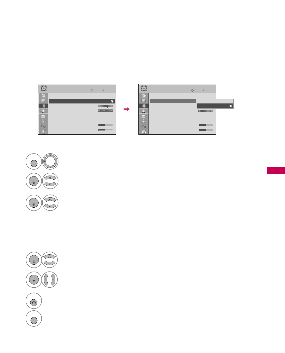
SOUND & LANGUAGE CONTROL
71
CLEAR VOICE II
By differentiating the human sound range from others, it improves the sound quality of voices.
Enter
Move
AUDIO
E
LR
Enter
Move
AUDIO
E
LR
Auto Volume : Off
Clear Voice II : On
• Level 3
Balance 0
Sound Mode : Standard
•
SRS TruSurround XT:
Off
• Treble 50
• Bass 50
Auto Volume : Off
Clear Voice II : On
• Level 3
Balance 0
Sound Mode : Standard
•
SRS TruSurround XT:
Off
• Treble 50
• Bass 50
-+ -+
Off
On
Select AUDIO.
Select Clear Voice II.
Select O n or O ff.
1
MENU
3
2
ENTER
ENTER
6
RETURN
Return to the previous menu.
MENU
Return to TV viewing.
Select Level.
4
ENTER
Make appropriate adjustments.
5
ENTER
Adjustment for Clear Voice ll Level
With selecting O n
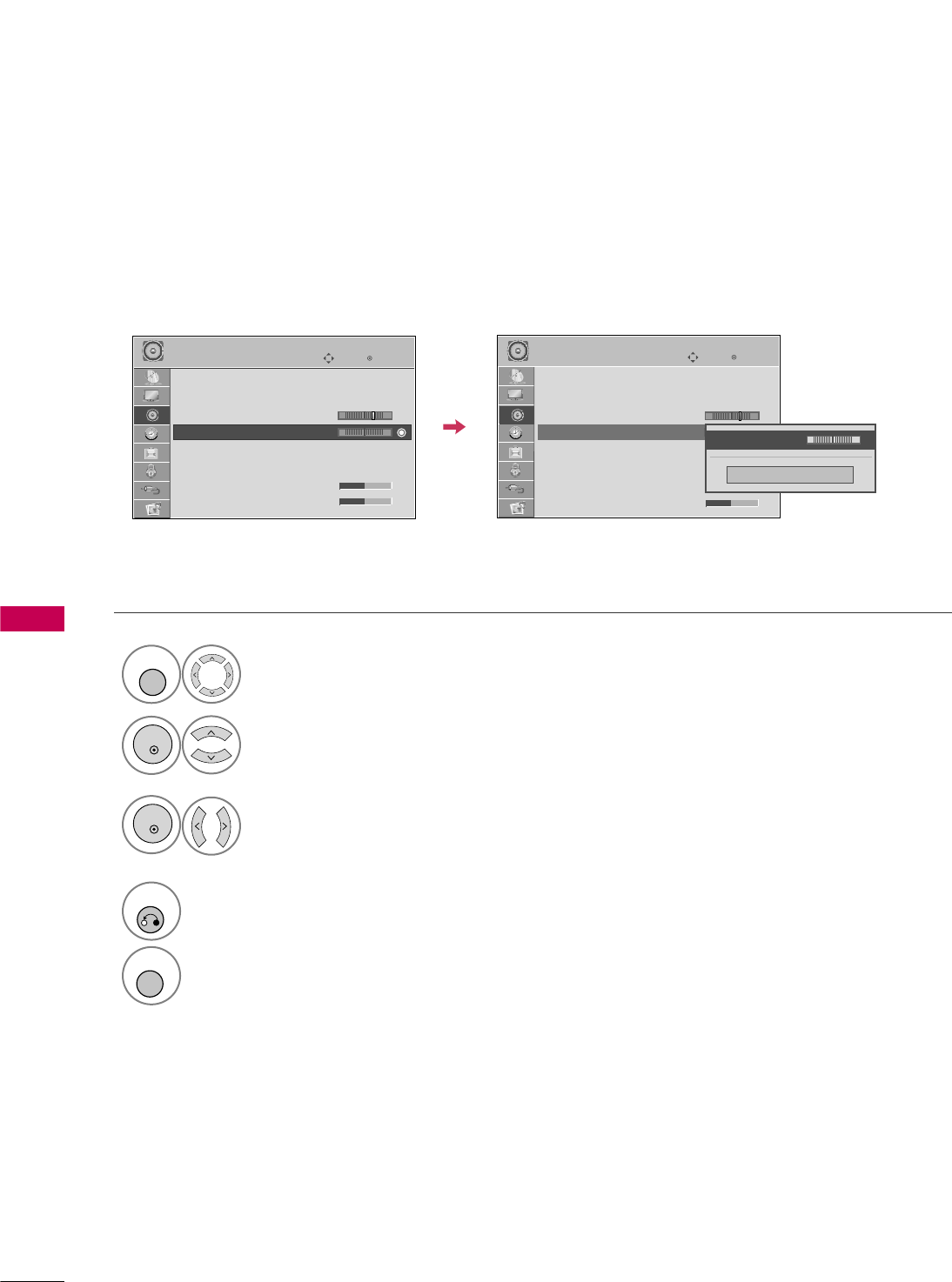
SOUND & LANGUAGE CONTROL
72
SOUND &LANGUAGE CONTROL
BALANCE
Select AUDIO.
Select Balance.
Make appropriate adjustments.
1
MENU
3
2
ENTER
ENTER
Adjust the left/right sound of speaker to suit your taste and room situations.
4
RETURN
Return to the previous menu.
MENU
Return to TV viewing.
Enter
Move
AUDIO
Enter
Move
AUDIO
LR
E
Auto Volume : Off
Clear Voice II : Off
• Level 3
Balance 0
Sound Mode : Standard
•
SRS TruSurround XT:
Off
• Treble 50
• Bass 50
LR
E
Auto Volume : Off
Clear Voice II : Off
• Level 3
Balance 0
Sound Mode : Standard
•
SRS TruSurround XT:
Off
• Treble 50
• Bass 50
Close
E
E
Balance 0 LR
-+ -+
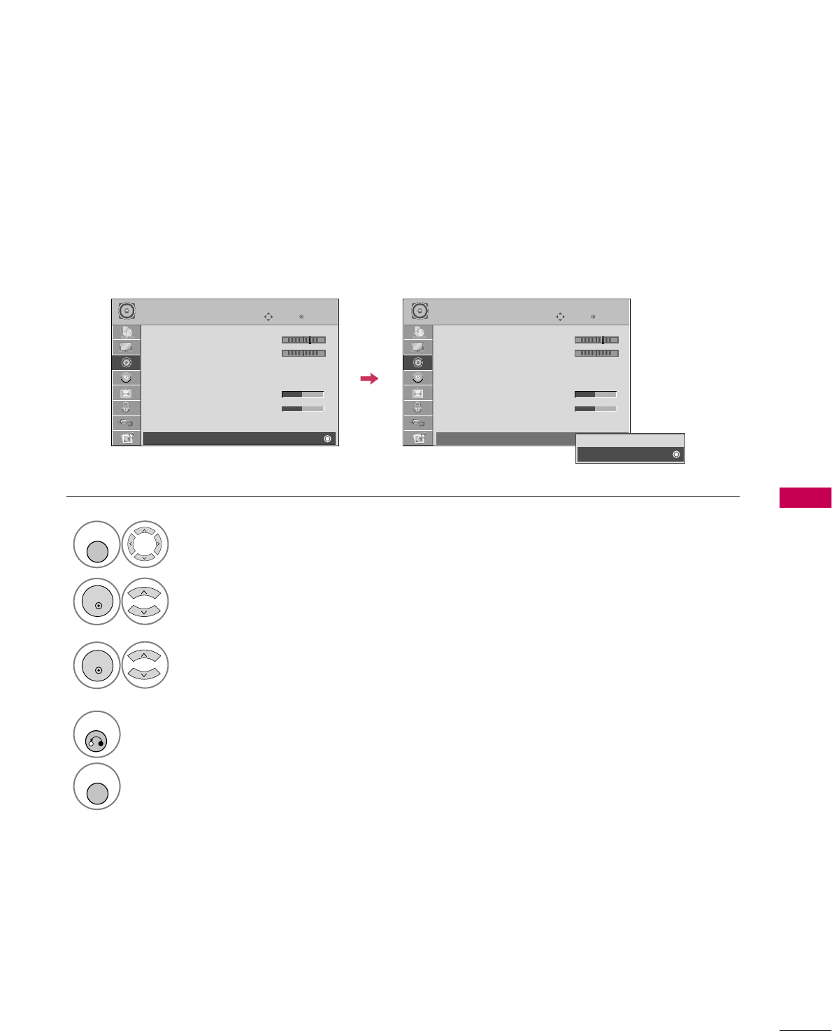
SOUND & LANGUAGE CONTROL
73
TV SPEAKERS ON/OFF SETUP
If you wish to use an external Hi-Fi system or a SRS System, turn off the TV’s internal speakers.
In A V, Component, RGB and HDMI with HDMI to DVI cable, the TV speaker can be operational even when
there is no video signal.
Turn the TV speakers off if using external audio equipment.
Select AUDIO.
Select TV Speaker.
Select O n or Off.
1
MENU
3
2
ENTER
ENTER
4
RETURN
Return to the previous menu.
MENU
Return to TV viewing.
Enter
Move
AUDIO
E
• Level 3
Balance 0
Sound Mode : Standard
•
SRS TruSurround XT:
Off
• Treble 50
• Bass 50
• Reset
TV Speaker : On
LR
Enter
Move
AUDIO
E
• Level 3
Balance 0
Sound Mode : Standard
•
SRS TruSurround XT:
Off
• Treble 50
• Bass 50
• Reset
TV Speaker : On
LR
Off
On
-+ -+
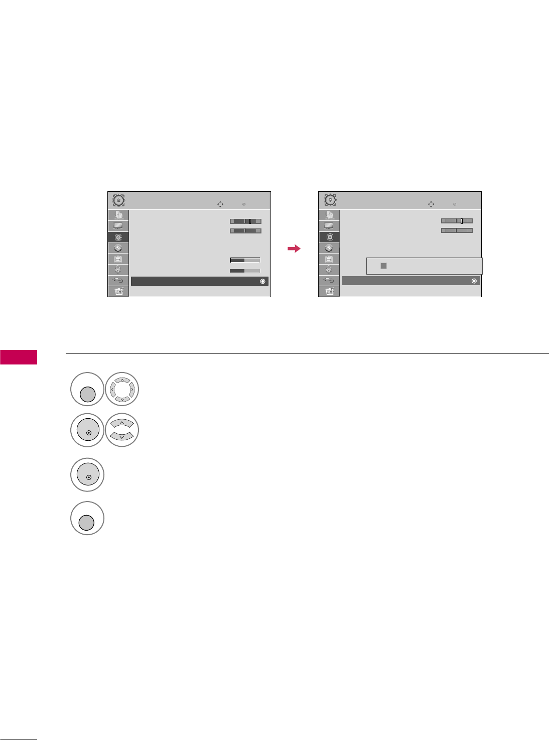
SOUND & LANGUAGE CONTROL
74
SOUND &LANGUAGE CONTROL
E
AUDIO RESET
Settings of the selected Sound Mode return to the default factory settings.
Select AUDIO.
Select Reset.
1
MENU
2
ENTER
Initialize the adjusted value.
3
ENTER
MENU
Return to TV viewing.
4
Enter
Move
AUDIO
E
• Level 3
Balance 0
Sound Mode : Standard
•
SRS TruSurround XT:
Off
• Treble 50
• Bass 50
• Reset
LR
Enter
Move
AUDIO
E
• Level 3
Balance 0
Sound Mode : Standard
•
SRS TruSurround XT:
Off
• Treble 50
• Bass 50
• Reset
LR
Resetting audio configuration...
i
-+ -+
E
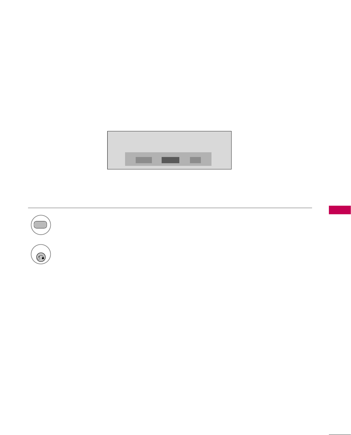
SOUND & LANGUAGE CONTROL
75
Each time you press the SAP button,
Mono, Stereo, or SAP appear in turn.
Return to TV viewing.
1
SAP
2
STEREO/SAP BROADCAST SETUP
For Analog only: This TV can receive MTS stereo programs and any SAP (Secondary Audio Program) that accom-
panies the stereo program if the station transmits an additional sound signal. Mono sound is automatically used
if the broadcast is only in Mono.
If other languages are available on the digital signal,select them with the SAP button.
RETURN
MONO SAPSTEREO