LG Electronics USA 42PC3DUUE Plasma Display Panel User Manual 38289U0527F LG PDP
LG Electronics USA Plasma Display Panel 38289U0527F LG PDP
UserManual.wiki
>
LG Electronics USA
>
42PC3DUUE User Manual
>
User Manual 1
Contents
1.
User Manual 1
2.
User Manual 2
3.
User Manual 3
User Manual 1
Navigation menu
Upload a User Manual
Namespaces
Wiki Guide
HTML
PDF
Info
Views
User Manual
Discussion / Help
Navigation

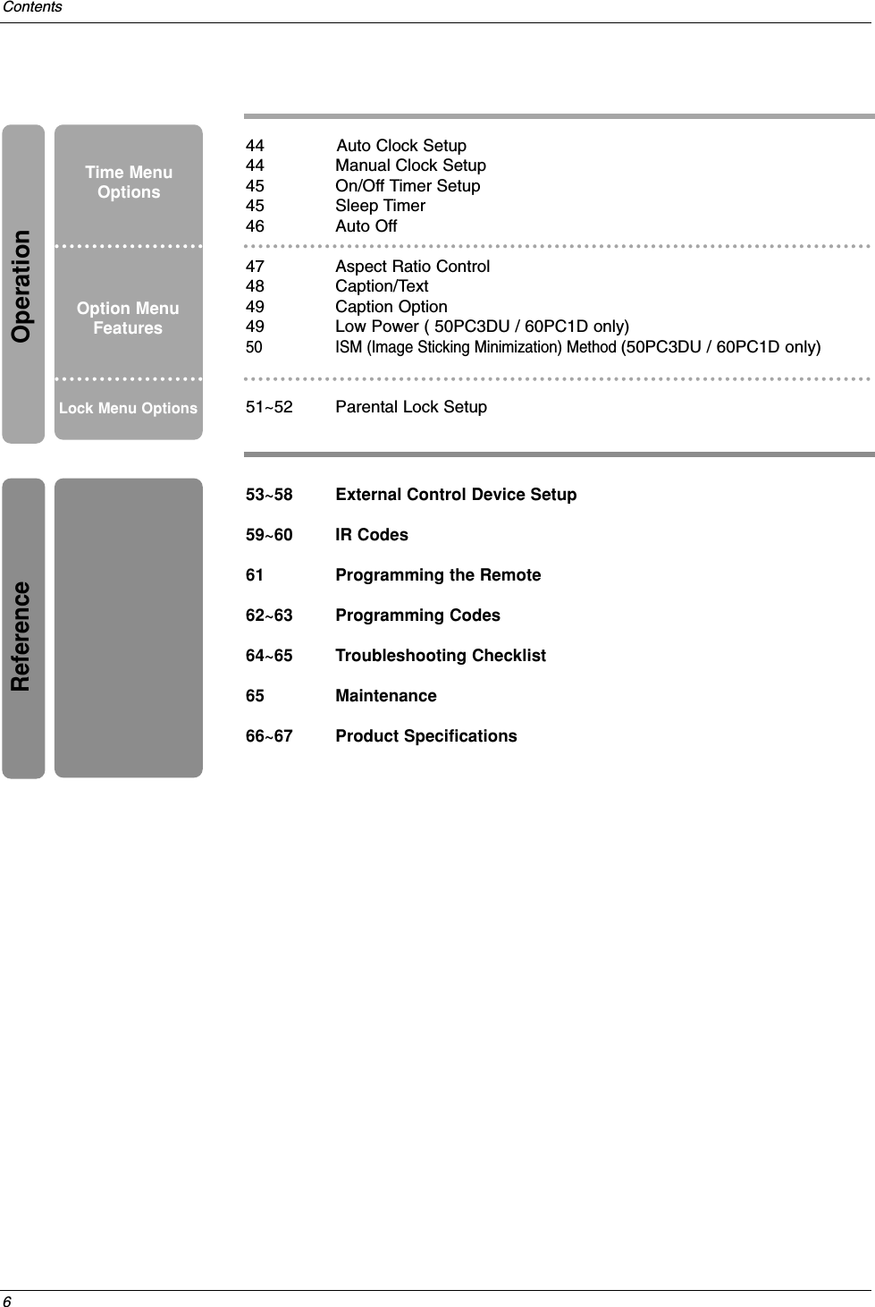
![7IntroductionAccessoriesAccessoriesIntroductionIntroductionOwner’s Manual75ΩRound CablePower CordEnsure that the following accessories are included with your TV. If any accessory is missing, please contact thedealer from where you purchased the product. User must use shielded signal interface cables(D-sub 15 pin cable)with ferrite cores to maintain standard compliance for the product.1.5V1.5VVOLFLASHBKCHPOW1 2 3 4 5 6 7809 APMADJUSTSAPEZ SOUNDEZ PICFREEZEAUDIODAY -CABLEGUIDEMENUMUTEPAGEPAGEFAVDAY+STBEXITTIMERCCTVDVDMODEINFOENTERVOLCHPOWER1 2 3 4 5 6 7809 MENUMUTEFAVRATIODAY -GUIDEDAY+RATIOVCRTVDVDENTERAPMADJUSTSAPEZ SOUNDEZ PICFREEZEFLASHBKPAGEPAGEEXITTIMERCCINFOAUDIOCABLESTBMODETV INPUTINPUTTV INPUTRemote Control /Batteries2-eye-bolts 2-TV brackets2-Wall brackets2-TV Bracket BoltsFor 32/37/42LC2DUFor 42PC3DU/3DVU/50PC3DUTwister HolderArrange the wires with the twister holder.CableManagement(Refer p.16)2-Wall brackets42PC3DU/3DVU only2-bolts(Refer p.14)4-bolts for standassemblySee below for detailinformation.32LC2DU only42LC2DU onlyPolishing ClothPolish the TV withthe cloth.Carefully place the product screen side down on acushioned surface that will protect product andscreen from damage.1Place the hook of the stand in the back of theproduct as shown.2Install the 4 bolts provided securely, in the back of theproduct.3Stand Installation for 32LC2DU[Polishing Cloth]Slightly wipe stained spot on the exterior only with the cleansing cloths for the product exterior ifthere is stain or fingerprint on surface of the exterior. Do not wipe roughly when removing stain. Please be cautious of that excessive power may causescratch or discoloration. Option ExtrasD-sub 15 pin cable 4-RING SPACERFor 60PC1D2-TV brackets2-Wall brackets4- Bolts](https://usermanual.wiki/LG-Electronics-USA/42PC3DUUE.User-Manual-1/User-Guide-693768-Page-7.png)