LG Electronics USA 42PC3DVUUE Plasma Display Panel User Manual 38289U0527F LG PDP
LG Electronics USA Plasma Display Panel 38289U0527F LG PDP
Contents
- 1. User Manual 1
- 2. User Manual 2
- 3. User Manual 3
User Manual 2
17
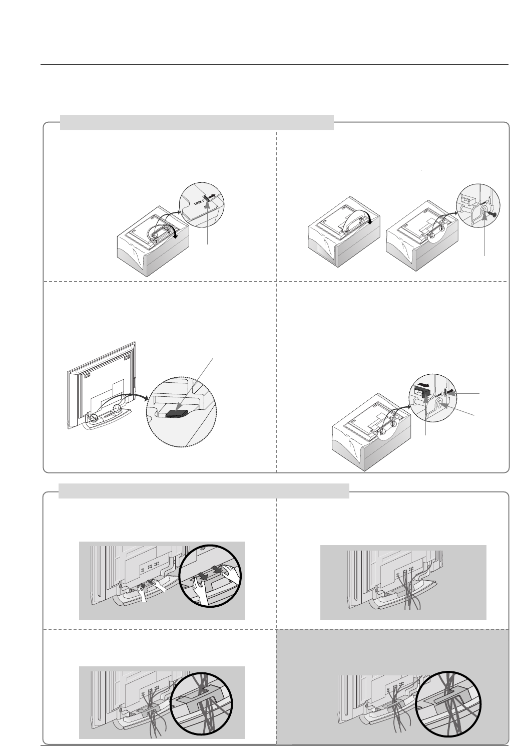
Place the set with the screen facing down on
a cushion or soft cloth as shown.
Before unfolding the stand, please make sure
two locks (A) on the bottom of the stand push
outward.
Pull the stand out as shown.
After unfolding the stand, please insert and
tighten the screws (provided as parts of the
product) in the holes (B) on the bottom of the
stand.
12
When connecting cables to the set, Do not
disengage the lock (C).
This may cause the set to fall, causing serious
bodily injury and serious damage to the set.
3
Basic Connection
Basic Connection
(C)
Hold the CABLE MANAGEMENT with both
hands and push it as shown.
Connect the cables as necessary.
To connect an additional equipment, see the
External equipment Connections section.
Reinstall the CABLE MANAGEMENT as
shown.
12
3
* Image shown here may be slightly different from
your set.
When closing the stand for storage
- First remove the screws in the holes (B) on the bottom
of the stand. And then pull two Hooks (D) of the stand
bottom and fold the stand into the back of the set.
- After folding, push the two Locks (A) of the stand
bottom outward.
(A)
(B)
(D)
(A)
(B)
How to use stand (For 42PC3DU/3DVU)
How to arrange the cable (For 50PC3DU)
For 60PC1D, 42PC3DU/3DVU
Arrange the cable as shown.
18
Installation
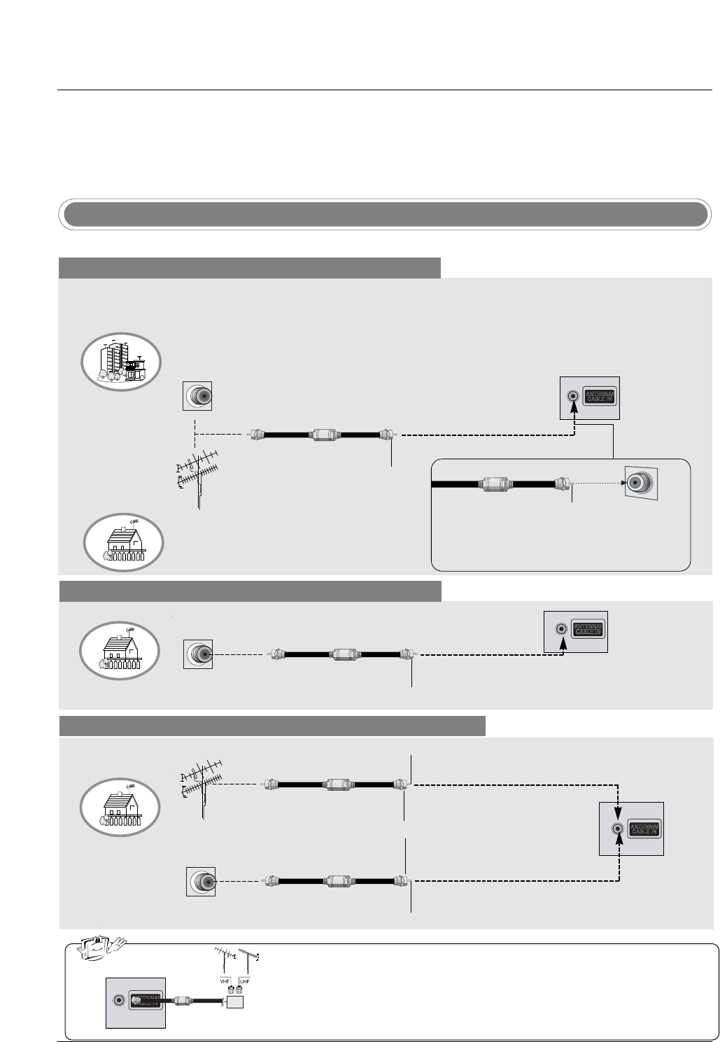
Antenna Or Cable Connection
Multi-family Dwellings/Apartments
(Connect to wall antenna socket)
Single-family Dwellings /Houses
(Connect to wall jack for outdoor antenna)
Outdoor Antenna
Wall Antenna Socket
VHF Antenna
UHF Antenna
RF Coaxial Wire (75 ohm)
Turn clockwise to tighten.
VIDEO
AUDIO
VIDEO
AUDIO
( )
S-VIDEO
AV IN 1
AV OUT
ANTENNA/
CABLE IN
COMPONENT IN
DIGITAL AUDIO
OUT
OPTICAL
VIDEO
AUDIO
VIDEO
AUDIO
( )
S-VIDEO
AV IN 1
AV OUT
COMPONENT IN
Bronze Wire
Be careful not to bend the bronze wire when
connecting the antenna.
Analog and Digital TV signals provided on antenna
- Antenna or Cable Service without a Cable Box Connection.
- For optimum picture quality, adjust antenna direction if needed.
Analog and DTV signals provided on two separate antennas
Cable TV Wall Jack
RF Coaxial Wire (75 ohm)
Bronze Wire
Bronze Wire
Turn clockwise to tighten.
Antenna
RF Coaxial Wire (75 ohm)
•In a poor signal area to improve picture quality, purchase and install a sig-
nal amplifier.
•If the antenna needs to be split for two TV’s, install a “2-Way Signal Splitter”
in the connections.
•If the antenna is not installed properly, contact your dealer for assistance.
VIDEO
AUDIO
VIDEO
AUDIO
( )
S-VIDEO
AV IN 1
AV OUT
ANTENNA/
CABLE IN
COMPONENT IN
DIGITAL AUDIO
OUT
OPTICAL
VIDEO
AUDIO
VIDEO
AUDIO
( )
S-VIDEO
AV IN 1
AV OUT
COMPONENT IN
External Equipment Connections
External Equipment Connections
signal
amplifier
VIDEO
AUDIO
VIDEO
AUDIO
( )
S-VIDEO
AV IN 1
AV OUT
ANTENNA/
CABLE IN
COMPONENT IN
DIGITAL AUDIO
OUT
OPTICAL
VIDEO
AUDIO
VIDEO
AUDIO
( )
S-VIDEO
AV IN 1
AV OUT
COMPONENT IN
NOTE: All cables shown are not included with the TV
Cable TV Wall Jack
RF Coaxial Wire (75 ohm)
Turn clockwise to tighten.
Analog and Digital TV signals provided on cable
VIDEO
AUDIO
VIDEO
AUDIO
( )
S-VIDEO
AV IN 1
AV OUT
ANTENNA/
CABLE IN
COMPONENT IN
DIGITAL AUDIO
OUT
OPTICAL
VIDEO
AUDIO
VIDEO
AUDIO
( )
S-VIDEO
AV IN 1
AV OUT
COMPONENT IN
19
Installation
- To avoid picture noise (interference), leave an adequate distance between the VCR and TV.
- Typically a frozen still picture from a VCR. If the 4:3 picture format is used; the fixed images on the sides
of the screen may remain visible on the screen.
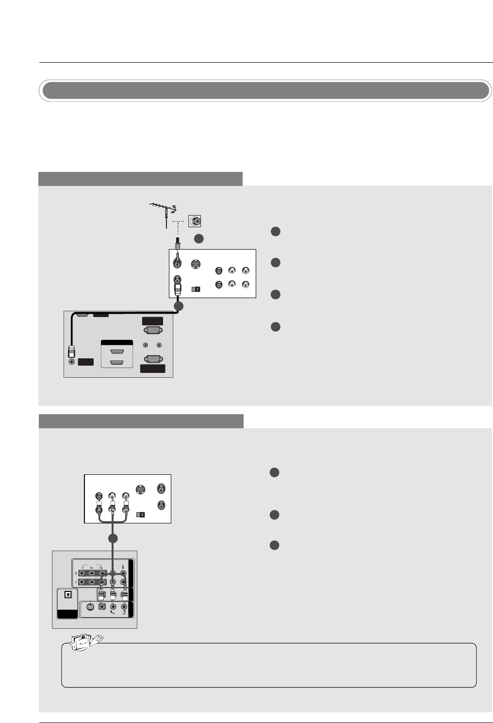
VCR Setup
When connecting with an antenna
VIDEO
AUDIO
VIDEO
AUDIO
( )
S-VIDEO
AV IN 1
AV OUT
COMPONENT IN
DIGITAL AUDIO
OUT
OPTICAL
S-VIDEO OUT
IN
(R) AUDIO (L) VIDEO
34
OUTPUT
SWITCH
ANT OUT
ANT IN
ANTENNA/ANTENNA/
CABLE INCABLE IN
REMOTEREMOTE
CONTROL INCONTROL IN
RS-232C INRS-232C IN
(CONTROL(CONTROL & SER & SERVICE)VICE)
RGB IN
(PC)(PC)
AUDIO INAUDIO IN
(RGB/DVI)(RGB/DVI)
VIDEO
AUDIO
VIDEO
AUDIO
( )
S-VIDEO
AV IN 1
AV OUT
COMPONENT IN
DIGITAL AUDIO
OUT
OPTICAL
SERVICESERVICE
HDMI IN
1(DVI)1(DVI)
2
When connecting with a RCA cable
VIDEO
AUDIO
VIDEO
AUDIO
( )
S-VIDEO
AV IN 1
AV OUT
COMPONENT IN
DIGITAL AUDIO
OUT
OPTICAL
S-VIDEO
OUT
IN
(R) AUDIO (L) VIDEO
34
OUTPUT
SWITCH
ANT OUT
ANT IN
HDMI / DVI IN
ANTENNA/
CABLE IN
REMOTE
CONTROL IN
RS-232C IN
(CONTROL & SERVICE)
RGB IN
(PC)
AUDIO IN
(RGB/DVI)
VIDEOVIDEO
AUDIOAUDIO
VIDEOVIDEO
AUDIOAUDIO
MONO
( )
S-VIDEOS-VIDEO
AV IN 1
AV OUT
COMPONENTCOMPONENT IN
DIGITAL AUDIO
OUTOUT
OPTICALPTICAL
SERVICE
VCR
1
2
3
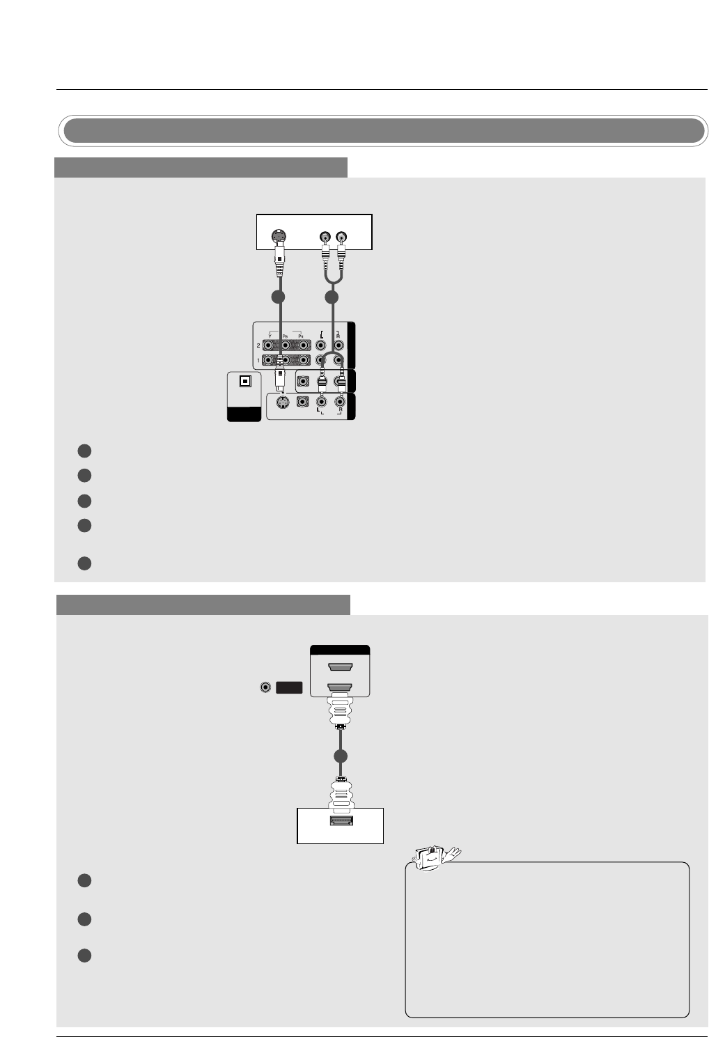
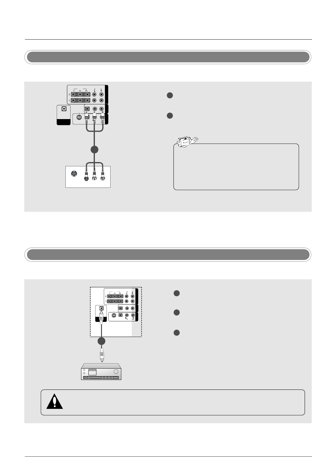
Connect the AUDIO/VIDEO jacks between TV
and VCR. Match the jack colors (Video = yellow,
Audio Left = white, and Audio Right = red)
Insert a video tape into the VCR and press PLAY
on the VCR. (Refer to the VCR owner’s manual.)
Select AV1 input source using the INPUT button
on the remote control.
- If connected to AV IN2, select AV2 input source.
•If you have a mono VCR, connect the audio cable from the VCR to the AUDIO L/MONO jack of the
set.
1
1
2
3
4
Connect the RF antenna out socket of the VCR to
the Antenna socket on the set.
Connect the antenna cable to the RF antenna in
socket of the VCR.
Set VCR output switch to 3 or 4 and then tune TV
to the same channel number.
Insert a video tape into the VCR and press PLAY
on the VCR. (Refer to the VCR owner’s manual.)
VCR
1
2
20
Installation
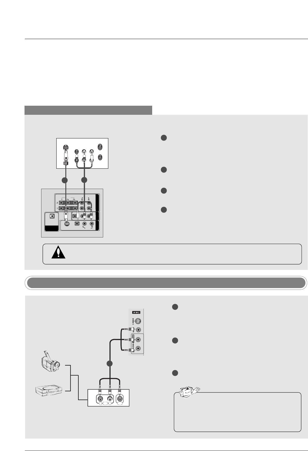
When connecting with an S-Video cable
VIDEO
AUDIOAUDIO
VIDEO
AUDIOAUDIO
MONO
( )
S-VIDEOS-VIDEO
AV IN 1
AV OUT
COMPONENTCOMPONENT IN IN
DIGITDIGITALAL AUDIO AUDIO
OUT
OPTICALPTICAL
S-VIDEO
OUT
IN
(R) AUDIO (L) VIDEO
34
OUTPUT
SWITCH
ANT OUT
ANT IN
HDMI / DVI IN
ANTENNA/
CABLE IN
REMOTE
CONTROL IN
RS-232C IN
(CONTROL & SERVICE)
RGB IN
(PC)
AUDIO IN
(RGB/DVI)
VIDEO
AUDIO
VIDEO
AUDIO
( )
S-VIDEO
AV IN 1
AV OUT
COMPONENT IN
DIGITAL AUDIO
OUT
OPTICAL
SERVICE
VCR
1
1
2
2
3
4
Connect the S-VIDEO output of the VCR to the S-
VIDEO input on the set. The picture quality is
improved; compared to normal composite (RCA
cable) input.
Connect the audio outputs of the VCR to the
AUDIO input jacks on the set.
Insert a video tape into the VCR and press PLAY
on the VCR. (Refer to the VCR owner’s manual.)
Select AV1 input source with using the INPUT
button on the remote control.
- If connected to AV IN2, select AV2 input source.
Do not connect to both Video and S-Video at the same time. In the event that you connect
both Video and the S-Video cables, only the S-Video will work.
R
L
AUDIO VIDEO
Camcorder
Video Game Set
1
1
2
3
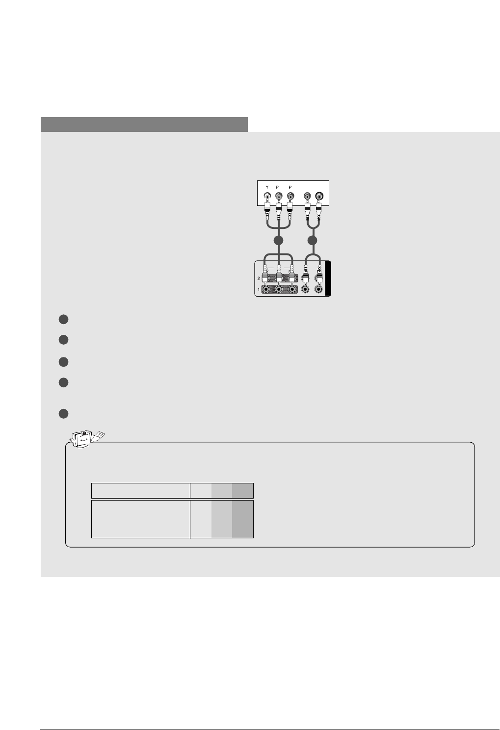
Connect the AUDIO/VIDEO jacks between TV
and external equipment. Match the jack colors
(Video = yellow, Audio Left = white, and Audio
Right = red).
Select AV2 input source with using the INPUT
button on the remote control.
- If connected to AV IN1 input, select AV1 input
source.
Operate the corresponding external equipment.
Refer to external equipment operating guide.
External AV Source Setup
•This TV finds the connected input sources
automatically for AV1, AV2, Component 1-2,
RGB, HDMI1/DVI and HDMI2 sources are
connected.
21
Installation
DVD Setup
When connecting with a S-Video cable
HDMI / DVI IN
ANTENNA/
CABLE IN
VIDEOVIDEO
AUDIOAUDIO
VIDEOVIDEO
AUDIOAUDIO
MONO
( )
S-VIDEOS-VIDEO
AV IN 1V IN 1
AV OUTV OUT
COMPONENTCOMPONENT IN IN
DIGITDIGITALAL AUDIO AUDIO
OUTOUT
OPTICALPTICAL
VIDEO
AUDIO
COMPONENT IN
S-VIDEO (R) AUDIO (L)
DVD
1
1
2
2
3
4
5
Connect the S-VIDEO output of the DVD to the S-VIDEO input on the set.
Connect the audio outputs of the DVD to the AUDIO input jacks on the set.
Turn on the DVD player, insert a DVD.
Select AV1 input source with using the INPUT button on the remote control.
- If connected to AV IN2, select AV 2 input source.
Refer to the DVD player's manual for operating instructions.
When connecting with a HDMI cable
1
2
3
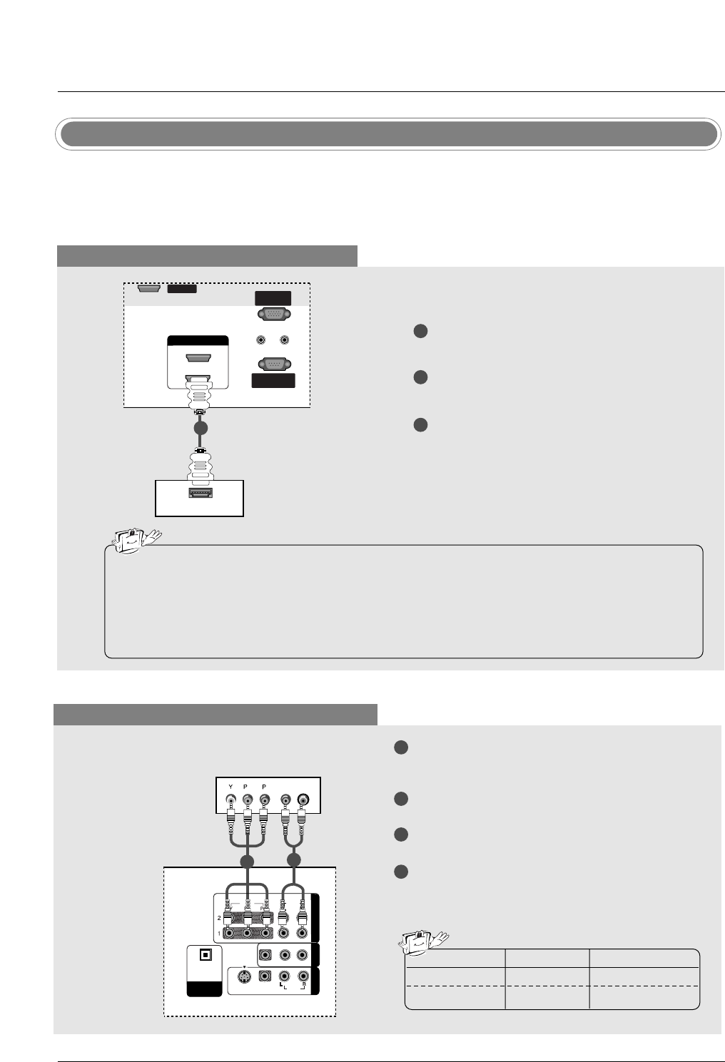
Connect the HDMI output of the DVD to the HDMI
IN 1(DVI) or 2jack on the set.
Select HDMI1/DVI or HDMI2 input source with
using the INPUT button on the remote control.
Refer to the DVD player's manual for operating
instructions.
ANTENNA/ANTENNA/
CABLE INCABLE IN
VIDEO
AUDIO
VIDEO
AUDIO
( )
S-VIDEO
AV IN 1
AV OUT
COMPONENT IN
DIGITAL AUDIO
OUT
OPTICAL
VIDEO
AUDIO
COMPONENT IN
HDMI-DVD OUTPUT
HDMI IN HDMI IN
1(DVI)
2
DVD
1
•TV can receive the video and audio signal
simultaneously with using a HDMI cable.
•If the DVD supports Auto HDMI function, the
DVD output resolution will be automatically
set to 1280x720p.
•If the DVD does not support Auto HDMI, you
need to set the output resolution appropriate-
ly. To get the best picture quality, adjust the
output resolution of the DVD to 1280x720p.
22
Installation
When connecting with a component cable
1
2
3
4
5
Connect the video outputs (Y, PB, PR) of the DVD to the COMPONENT IN VIDEO jacks on the set.
Connect the audio outputs of the DVD to the COMPONENT IN AUDIO jacks on the set.
Turn on the DVD player, insert a DVD.
Select Component 1 input source with using the INPUT button on the remote control.
- If connected to COMPONENT 2, select Component 2 input source.
Refer to the DVD player's manual for operating instructions.
•Component Input ports
To get better picture quality, connect a DVD player to the component input ports as shown below.
Y PBPR
Component ports on the TV
Y
Y
Y
Y
Pb
B-Y
Cb
PB
Pr
R-Y
Cr
PR
Video output ports
on DVD player
HDMI / DVI IN
ANTENNA/
CABLE IN
VIDEO
AUDIO
VIDEO
AUDIO
( )
S-VIDEO
AV IN 1
AV OUT
COMPONENT IN
DIGITAL AUDIO
OUT
OPTICAL
VIDEO
AUDIOAUDIO
COMPONENTCOMPONENT IN
BR
(R) AUDIO (L)
DVD
1 2
23
Installation
- This TV can receive Digital Over-the-air/Cable signals without an external digital set-top box. However, if
you do receive Digital signals from a digital set-top box or other digital external device, refer to the figure
as shown below.
HDSTB Setup
When connecting with a HDMI cable
1
2
3
Connect the HDMI output of the digital set-top
box to the HDMI IN 1(DVI) or 2jack on the set.
Select HDMI1/DVI or HDMI2 input source with
using the INPUT button on the remote control.
Turn on the digital set-top box. (Refer to the
owner’s manual for the digital set-top box.)
Digital Set-top Box
•TV can receive the video and audio signal simultaneously using a HDMI cable.
•If the digital set-top box supports Auto HDMI function, output resolution of the digital set-top box will
be automatically set to 1280x720p.
•If the digital set-top box does not support Auto HDMI, you need to set the output resolution appro-
priately. To get the best picture quality, adjust the output resolution of the digital set-top box to
1280x720p.
RGB IN
REMOTE
CONTROL IN
RS-232C IN
(CONTROL & SERVICE)
RGB IN
(PC)
AUDIO IN
(RGB/DVI)
HDMI-DTV OUTPUT
REMOTE
CONTROL IN
RS-232C IN
(CONTROL & SERVICE)
RGB IN
(PC)
AUDIO IN
(RGB/DVI)
REMOTEREMOTE
CONTROL INCONTROL IN
RS-232C INRS-232C IN
(CONTROL(CONTROL & SER & SERVICE)VICE)
RGB INRGB IN
(PC)(PC)
AUDIO INAUDIO IN
(RGB/DVI)(RGB/DVI)
VIDEO
AUDIO
VIDEO
AUDIO
( )
S-VIDEO
AV IN 1
AV OUT
COMPONENT IN
DIGITAL AUDIO
OUT
OPTICAL
SERVICE
SERVICESERVICE
HDMI IN HDMI IN
1(DVI)
2
HDMI IN
1(DVI)
2
1
When connecting with a Component cable
1
2
3
4
Connect the video outputs (Y, PB, PR) of the digi-
tal set-top box to the COMPONENT IN VIDEO
jacks on the set.
Connect the audio output of the digital set-top box
to the COMPONENT IN AUDIO jacks on the set.
Turn on the digital set-top box. (Refer to the
owner’s manual for the digital set-top box.)
Select Component 1 input source with using the
INPUT button on the remote control.
- If connected to COMPONENT 2, select
Component 2 input source.
BR
(R) AUDIO (L)
RGB IN
REMOTE
CONTROL IN
RS-232C IN
(CONTROL & SERVICE)
RGB IN
(PC)
AUDIO IN
(RGB/DVI)
HDMI / DVI IN
REMOTE
CONTROL IN
RS-232C IN
(CONTROL & SERVICE)
RGB IN
(PC)
AUDIO IN
(RGB/DVI)
HDMI / DVI IN
REMOTE
CONTROL IN
RS-232C IN
(CONTROL & SERVICE)
RGB IN
(PC)
AUDIO IN
(RGB/DVI)
VIDEOVIDEO
AUDIOAUDIO
VIDEOVIDEO
AUDIOAUDIO
MONO
( )
S-VIDEOS-VIDEO
AV IN 1V IN 1
AV OUTV OUT
COMPONENTCOMPONENT IN
DIGITDIGITALAL AUDIO AUDIO
OUTOUT
OPTICALPTICAL
SERVICE
SERVICE
Signal
480i
480p/720p/1080i
Component1/2
Yes
Yes
HDMI1/DVI, HDMI2
No
Yes
2
1
Digital Set-top Box
24
Installation
When connecting with a HDMI to DVI cable
1
2
3
4
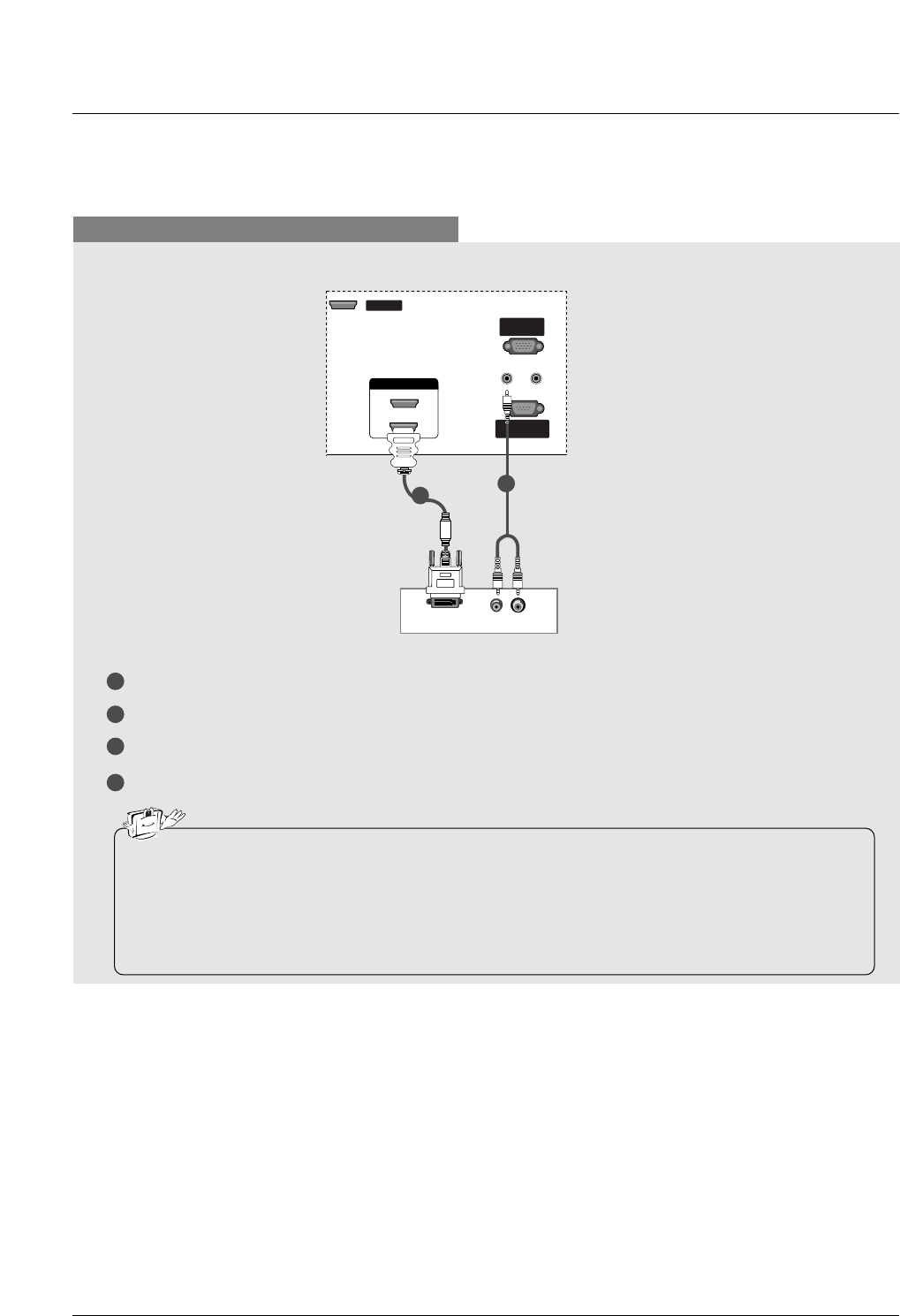
Connect the DVI output of the digital set-top box to the HDMI IN 1(DVI) jack on the set.
Connect the audio outputs of the set-top box to the AUDIO IN(RGB/DVI) jack on the set.
Turn on the digital set-top box. (Refer to the owner’s manual for the digital set-top box.)
Select HDMI1/DVI input source with using the INPUT button on the remote control.
RGB IN
(R) AUDIO (L)
DVI-DTV OUTPUT
REMOTE
CONTROL IN
RS-232C IN
(CONTROL & SERVICE)
RGB IN
(PC)
AUDIO IN
(RGB/DVI)
REMOTEREMOTE
CONTROL INCONTROL IN
RS-232C INRS-232C IN
(CONTROL(CONTROL & SER & SERVICE)VICE)
RGB INRGB IN
(PC)(PC)
AUDIO INAUDIO IN
(RGB/DVI)(RGB/DVI)
REMOTE
CONTROL IN
RS-232C IN
(CONTROL & SERVICE)
RGB IN
(PC)
AUDIO IN
(RGB/DVI)
VIDEO
AUDIO
VIDEO
AUDIO
( )
S-VIDEO
AV IN 1
AV OUT
COMPONENT IN
DIGITAL AUDIO
OUT
OPTICAL
SERVICESERVICE
SERVICE
HDMI IN
1(DVI)
2
HDMI IN HDMI IN
1(DVI)1(DVI)
2
Digital Set-top Box
1
2
• If the digital set-top box has a DVI output and no HDMI output, a separated audio connection is nec-
essary.
•If the digital set-top box supports Auto DVI function, the output resolution of the digital set-top box will
be automatically set to 1280x720p.
•If the digital set-top box does not support Auto DVI, you need to set the output resolution appropri-
ately. To get the best picture quality, adjust the output resolution of the digital set-top box to
1280x720p.
25
Installation
Digital Audio Output
1
2
3
Connect one end of an optical cable to the TV
Digital Audio Optical Output port.
Connect the other end of the optical cable to the
digital audio optical input on the audio equipment.
See the external audio equipment instruction
manual for operation.
When connecting with external audio equip-
ments, such as amplifiers or speakers, please
turn the TV speakers off. (Refer to p.43)
VIDEOVIDEO
AUDIOAUDIO
VIDEOVIDEO
AUDIOAUDIO
MONO
( )
S-VIDEOS-VIDEO
AV IN 1V IN 1
AV OUTV OUT
COMPONENT IN
DIGITDIGITALAL AUDIO AUDIO
OUTOUT
OPTICALPTICAL
- Send the TV’s audio to external audio equipment (stereo system) via the Digital Audio Output Optical port.
CAUTION
Do not look into the optical output port. Looking at the laser beam may damage your vision.
1/2
AV Out Setup
1
2
Connect the second TV or monitor to the TV’s AV
OUT jacks.
See the Operating Manual of the second TV or
monitor for further details regarding that device’s
input settings.
S-VIDEO IN
(R) AUDIO (L)
VIDEO
VIDEOVIDEO
AUDIOAUDIO
VIDEOVIDEO
AUDIOAUDIO
MONO
( )
S-VIDEOS-VIDEO
AV IN 1V IN 1
AV OUTV OUT
COMPONENTCOMPONENT IN
DIGITDIGITALAL AUDIO AUDIO
OUTOUT
OPTICALPTICAL
- The TV has a special signal output capability which allows you to hook up a second TV or monitor.
1/2 •Component 1-2, RGB-PC, HDMI1/DVI,
HDMI2, DTV input sources cannot be used
for Monitor out.
• We recommend to use the video and audio
output jacks for VCR recording.
26
Installation
- This TV provides Plug and Play capability, meaning that the PC adjusts automatically to the TV's settings.
PC Setup
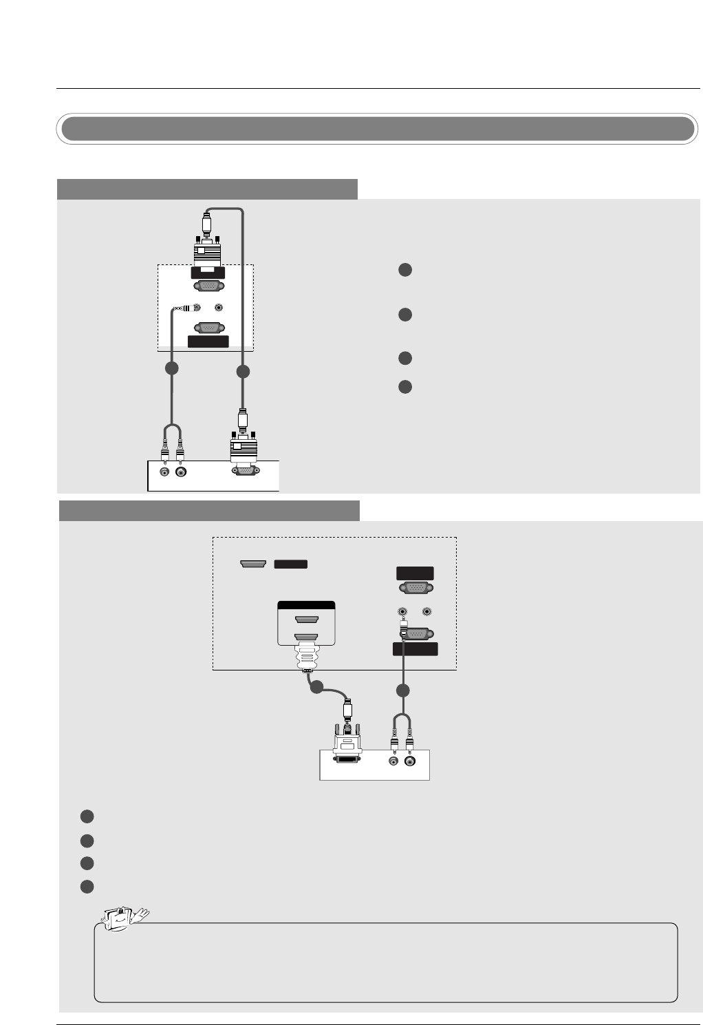
When connecting with a D-sub 15 pin cable
1
2
3
4
Connect the RGB output of the PC to the RGB IN
(PC) jack on the set.
Connect the PC audio outputs to the AUDIO
IN(RGB/DVI) jack on the set.
Turn on the PC and the set.
Select RGB-PC input source with using the
INPUT button on the remote control.
(R) AUDIO (L)
RGB-PC OUTPUT
REMOTE
CONTROL INCONTROL IN
RS-232C INRS-232C IN
(CONTROL(CONTROL & SER & SERVICE)VICE)
RGB IN
(PC)
AUDIO INAUDIO IN
(RGB/DVI)(RGB/DVI)
HDMI / DVI IN
REMOTE
CONTROL IN
RS-232C IN
(CONTROL & SERVICE)
RGB IN
(PC)
AUDIO IN
(RGB/DVI)
SERVICE
1
2
PC
When connecting with a HDMI to DVI cable
1
2
3
4
Connect the DVI output of the PC to the HDMI IN 1(DVI) jack on the set.
Connect the audio outputs of the PC to the AUDIO IN(RGB/DVI) jack on the set.
Turn on the PC and the set.
Select HDMI1/DVI input source with using the INPUT button on the remote control.
(R) AUDIO (L)
DVI-PC OUTPUT
REMOTE
CONTROL IN
RS-232C IN
(CONTROL & SERVICE)
RGB IN
(PC)
AUDIO IN
(RGB/DVI)
REMOTEREMOTE
CONTROL INCONTROL IN
RS-232C IN
(CONTROL & SERVICE)
RGB INRGB IN
(PC)
AUDIO IN
(RGB/DVI)
SERVICESERVICE
HDMI IN HDMI IN
1(DVI)1(DVI)
2
PC
• If the PC has a DVI output and no HDMI output, a separated audio connection is necessary.
•If the PC does not support Auto DVI, you need to set the output resolution appropriately. To get the
best picture quality, adjust the output resolution of PC graphics card's output resolution to
1024x768, 60Hz.
12
27
Installation
1. Depending on the graphics card, DOS mode may
not work if a HDMI to DVI Cable is in use.
2. When Source Devices connected with HDMI/DVI
Input, output PC Resolution (VGA, SVGA, XGA,
WXGA), Position and Size may not fit to
Screen.Press the ADJUST button to adjust the
screen Position of TV SET and contact an PC
graphics card service center.
3. When Source Devices connected with HDMI/DVI
Input, output TV SET Resolution (480p, 720p,
1080i. 1080p) and TV SET Display fit EIA/CEA-
861-B Specification to Screen. If not, refer to the
Manual of HDMI/DVI Source Devices or contact
your service center.
4. In case HDMI/DVI Source Devices is not connect-
ed Cable or poor cable connection, "NO SIGNAL"
OSD display in HDMI/DVI Input. In case that Video
Resolution is not supported TV SET output in
HDMI/DVI Source Devices, "INVALID FORMAT"
OSD display. Refer to the Manual of HDMI/DVI
Source Devices or contact your service center.
5. Check the image on your TV. There may be noise
associated with the resolution, vertical pattern,
contrast or brightness in PC, HDMI/DVI mode. If
noise is present, change the PC or HDMI/DVI
mode to another resolution, change the refresh
rate to another rate or adjust the brightness and
contrast on the menu until the picture is clear. If the
refresh rate of the PC graphic card can not be
changed, change the PC graphic card or consult
the manufacturer of the PC graphic card.
6. Avoid keeping a fixed image on the TV's screen for
a long period of time. The fixed image may become
permanently imprinted on the screen.
7. The synchronization input form for Horizontal and
Vertical frequencies is separate.
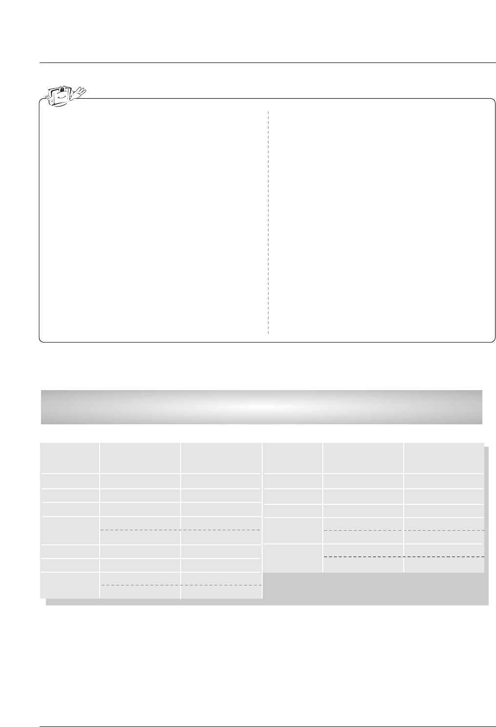
Supported Display Resolution
(RGB-PC, HDMI1/DVI, HDMI2 Mode)
Resolution
640x350
720x400
*720x480
Horizontal
Frequency (kHz)
31.468
31.469
31.469
70.08
59.94
70.08
Vertical
Frequency (Hz)
Resolution
Horizontal
Frequency (kHz)
47.776
47.720
47.130
33.716
33.750
27.000
33.750
59.87
59.80
59.65
59.94
60.00
24.00
30.00
Vertical
Frequency (Hz)
31.469
31.500
37.879
48.363
44.955
45.000
59.94
60.00
60.31
60.00
59.94
60.00
800x600
1024x768
*1920x1080i
* This format is only for HDMI-DTV input.
*1920x1080p
640x480
1280x768
1360x768
1366x768
*1280x720
• 42PC3DVU is not supported to 1280x768, 1360x768, 1366x768, 1920x1080P.
28
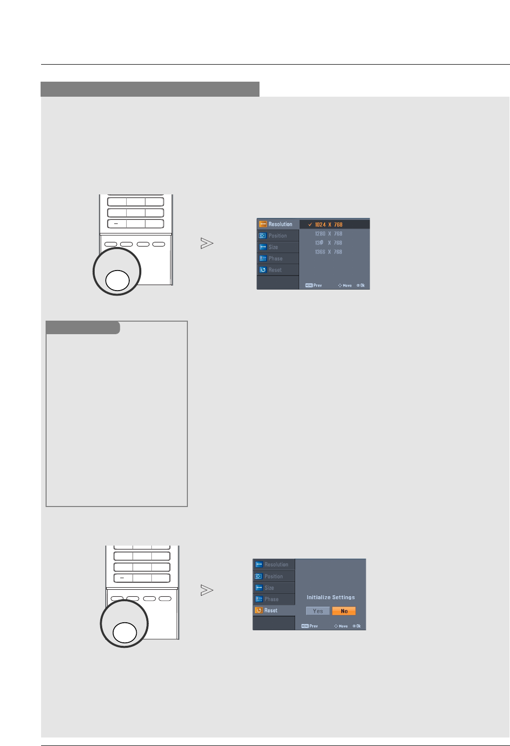
Installation
* Adjustment for screen Resolution, Position, Size, and Phase
* Initializing (Reset to original factory values)
- To initialize the adjusted values
Position This function is to adjust
picture to left/right and
up/down as you prefer.
Size This function is to minimize
any vertical bars or stripes
visible on the screen back-
ground. And the horizontal
screen size will also
change.
Phase This function allows you to
remove any horizontal noise
and clear or sharpen the
image of characters.
Resolution This function allows you
select Resolution of
XGA/WXGA.
Mini Glossary
- When RGB connect to PC input and select the RGB-PC, this function is used.
- When HDMI/DVI connect to PC input and select HDMI/DVI input, this function is used.
- After connecting RGB-PC or HDMI/DVI to PC input and checking the screen quality.
Press the ADJUST button and then use DD / EEbutton to select
Resolution, POSITION, SIZE, or PHASE.
Press ENTER button and then use DD / EE/ FF / GG buttons to
make appropriate adjustments.
• The PHASE adjustment range is -16 ~ +16.
(In HDMI/DVI-PC mode, PHASE is not available.)
• The SIZE adjustment range is -30 ~ +30.
(In HDMI/DVI-PC mode, SIZE is not available.)
Press ENTER button.
1
2
3
Press the ADJUST button and then use DD / EEbutton to select
the RESET option.
Press ENTER button and then use FF / GG button to select Yes.
Press ENTER button.
1
2
3
Screen Setup for PC mode
4 5 6
78
0
9
ADJUST
SAP
EZ SOUND
EZ PIC
CC
FLASHBK
ADJUST
1 2 3
4 5 6
78
0
9
ADJUST
SAP
EZ SOUND
EZ PIC
CC
FLASHBK
ADJUST
* When you change the resolution, select the proper resolution
in present input to see the best picture appearance.
29
Operation
Operation
Operation
Basic operation
Basic operation
1. First, connect power cord correctly. At this moment, the TV switches to standby mode.
In standby mode to turn TV on, press the , INPUT, CH DD/ EEbutton on the TV or press the POWER, TV
INPUT, INPUT, CH DD/ EE, Number (0 ~ 9) button on the remote control .
2. Select the viewing source by using TV INPUT, INPUT button on the remote control.
This TV is programmed to remember which power state it was last set to, even if the power cord is out.
3. When finished using the TV, press the POWER button on the remote control. The TV reverts to standby mode.
1. Press the VOL DD/ EEbutton to adjust the volume.
2. If you want to switch the sound off, press the MUTE button.
3. You can cancel this function by pressing the MUTE or VOL DD/ EEbutton.
Press the CH DD/ EEor NUMBER buttons to select a channel number.
- The menus can be shown on the
screen in the selected language.
First select your language.
On Screen Menus Language Selection
Volume Adjustment
Turning on the TV
Channel Selection
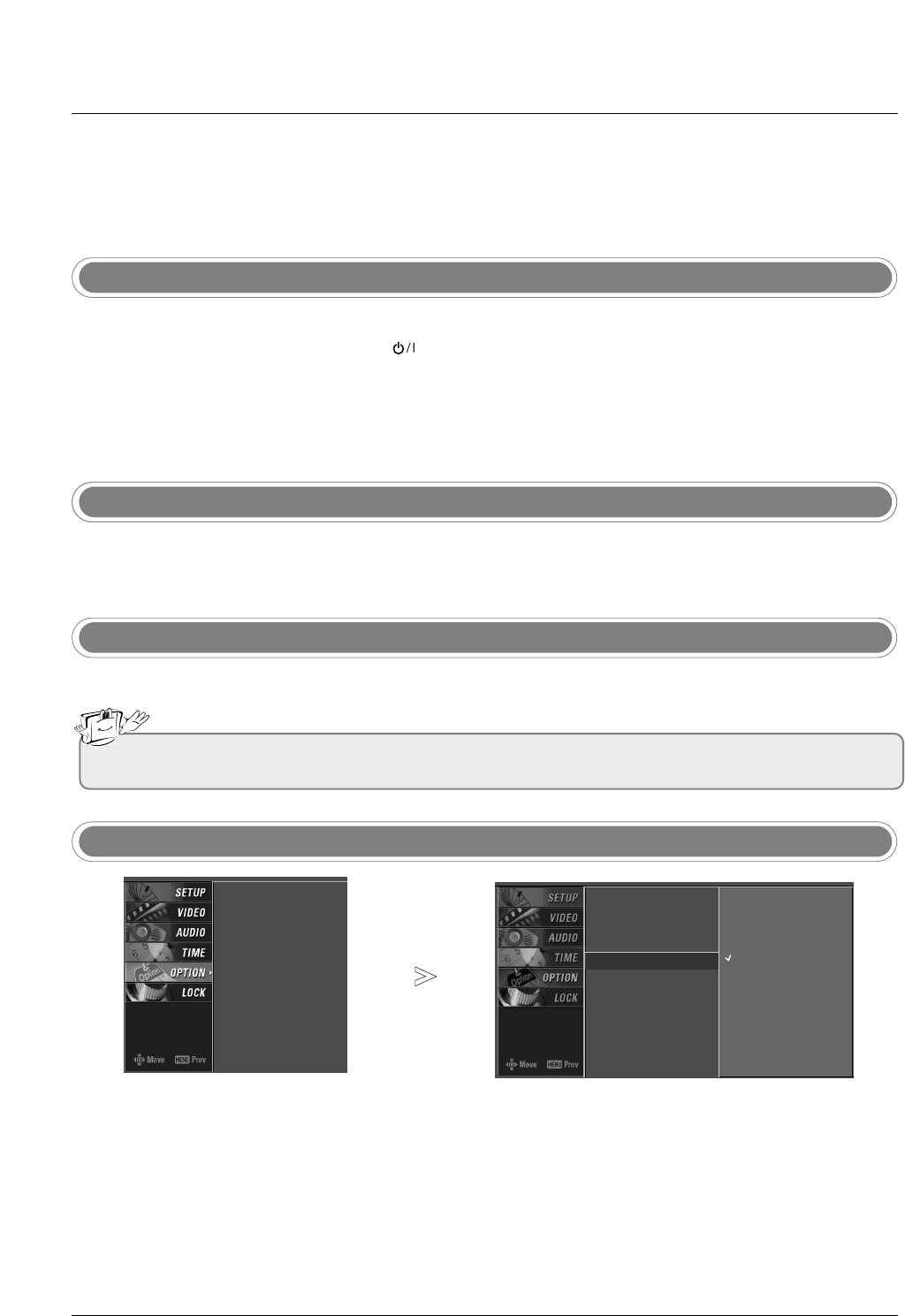
Press the MENU button and then use DD/ EEbutton to select the
OPTION menu.
Press the GGbutton and then use DD/ EEbutton to select Language.
Press the GGbutton and then use DD/ EEbutton to select your desired
language. From this point on, the on-screen menus will be shown in the
selected language.
Press EXIT button to return to TV viewing or press MENU button to
return to the previous menu.
1
2
3
4
• If you intend to be away on vacation, disconnect the power plug from the wall power outlet.
Aspect Ratio
Caption/Text
Caption Option
Language G
ISM Method
Low Power
English
Español (Spanish)
Français (French)
Aspect Ratio
Caption/Text
Caption Option
Language
ISM Method
Low Power
30
Operation
On Screen Menus Selection and
On Screen Menus Selection and Adjustment
Adjustment
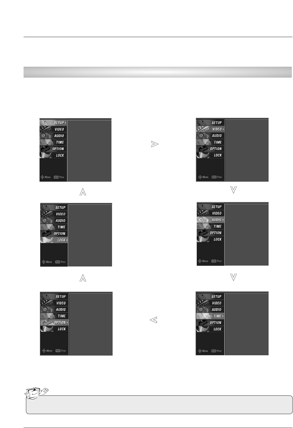
1. Press the MENU button and then DD/ EEbutton to select each menu.
2. Press the GGbutton and then use DD / EE/ FF / GGbutton to display the available menus.
• Your TV's OSD (On Screen Display) may differ slightly from what is shown in this manual.
How to adjust the OSD screen
EZ Scan
Manual Scan
Channel Edit
DTV Signal
Input Source
Input Label
Set ID
EZ Picture
Color Temperature
XD
Advanced
Video Reset
Audio Language
EZ Sound
Balance
TV Speaker
Auto Clock
Manual Clock
Off Timer
On Timer
Sleep Timer
Auto Off
Aspect Ratio
Caption/Text
Caption Option
Language
ISM Method
Low Power
Lock System
Set Password
Block Channel
Movie Rating
TV Rating-Children
TV Rating-General
Input Block
31
Operation
EZ Scan (Channel Search)
Setup Menu Options
Setup Menu Options
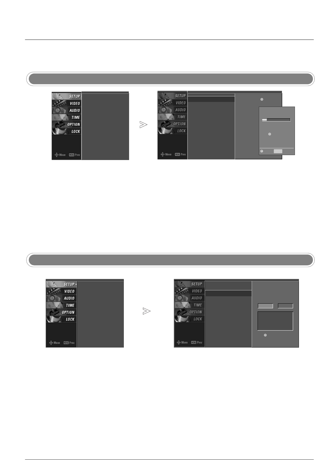
Press the MENU button and then use DD / EEbutton to select the SETUP menu.
Press the GGbutton and then use DD / EEbutton to select EZ Scan.
Press the ENTER button to begin the channel search.
Allow EZ Scan to complete the channel search cycle for ANTENNA, and
CABLE.
1
2
3
Manual Scan
- A password is required to gain
access to Manual Scan menu if
the Lock System is turned on.
Press the MENU button and then use DD / EEbutton to select the SETUP menu.
Press the GGbutton and then use DD / EEbutton to select Manual Scan.
Press the GGbutton and then use DD / EEbutton to select TV, DTV, CATV,
and CADTV.
Press the GGbutton and then use DD / EEbutton to select channel num-
ber you want to add or delete.
Press the ENTER button to add or delete for the channel number.
Press EXIT button to return to TV viewing or press MENU button to
return to the previous menu.
1
2
3
4
5
6
- Automatically finds all channels
available through antenna or
cable inputs, and stores them in
memory on the channel list.
- Run EZ Scan again after any
Antenna/Cable connection changes.
- A password is required to gain
access to EZ Scan menu if the
Lock System is turned on.
EZ Scan G
Manual Scan
Channel Edit
DTV Signal
Input Source
Input Label
Set ID
Selection ( Gor )
leads you to the EZ
scan screen.
EZ Scan
Manual Scan
Channel Edit
DTV Signal
Input Source
Input Label
Set ID
Processing EZ scan...
TV Ch.20
0 channel(s) found
Press to stop the
current scan and start
DIGITAL ANTENNA channel
scan.
MENU Previous
Next
EZ Scan
Manual Scan
Channel Edit
DTV Signal
Input Source
Input Label
Set ID
EZ Scan
Manual Scan G
Channel Edit
DTV Signal
Input Source
Input Label
Set ID
Select channel type and
RF-channel number.
TV GG2
Press
to delete the channel.
TV 2-0
DD
EE