LG Electronics USA 42PM1MUC Plasma Display User Manual U514Aen
LG Electronics USA Plasma Display U514Aen
Users Manual

PLASMA MONITOR
OWNER’S MANUAL
Please read this manual carefully and completely before oper-
ating your Monitor.
Retain this manual for future reference.
Record model number and serial number of the Monitor in the
spaces provided below.
See the label attached on the back cover and relate this infor-
mation to your dealer if you require service.
Model Number :
Serial Number :
MODELS: 42PM1M / 42PM3MV
50PM3MV
42PM1M-UC / 42PM3MV-UC
50PM3MV-UC
U514Aen 97/10/26 3:11 AM Page 1
2 Plasma Monitor
Warning/Caution
WARNING/CAUTION:
TO REDUCE THE RISK OF ELECTRIC SHOCK DO NOT REMOVE COVER (OR BACK). NO USER
SERVICEABLE PARTS INSIDE. REFER TO QUALIFIED SERVICE PERSONNEL.
The lightning flash with arrowhead symbol, within an equilateral triangle, is intended to alert the user to
the presence of uninsulated “dangerous voltage” within the product’s enclosure that may be of suffi-
cient magnitude to constitute a risk of electric shock to persons.
The exclamation point within an equilateral triangle is intended to alert the user to the presence of
important operating and maintenance (servicing) instructions in the literature accompanying the appli-
ance.
WARNING/CAUTION:
TO PREVENT FIRE OR SHOCK HAZARDS, DO NOT EXPOSE THIS PRODUCT TO RAIN OR MOISTURE.
FCC NOTICE
• A Class B digital device
This equipment has been tested and found to comply with the limits for a Class B digital device, pursuant to Part
15 of the FCC Rules. These limits are designed to provide reasonable protection against harmful interference in
a residential installation. This equipment generates, uses and can radiate radio frequency energy and, if not
installed and used in accordance with the instructions, may cause harmful interference to radio communications.
However, there is no guarantee that interference will not occur in a particular installation. If this equipment does
cause harmful interference to radio or television reception, which can be determined by turning the equipment off
and on, the user is encouraged to try to correct the interference by one or more of the following measures:
- Reorient or relocate the receiving antenna.
- Increase the separation between the equipment and receiver.
- Connect the equipment into an outlet on a circuit different from that to which the receiver is connected.
- Consult the dealer or an experienced radio/TV technician for help.
• Any changes or modifications not expressly approved by the party responsible for compli-
ance could void the user’s authority to operate the equipment.
CAUTION:
Do not attempt to modify this product in any way without written authorization from LG Electronics. Unauthorized mod-
ification could void the user’s authority to operate this product.
COMPLIANCE:
The responsible party for this product’s compliance is:
LG Electronics U.S.A., Inc
1000 Sylvan Avenue, Englewood Cliffs, NJ 07632
1-800-243-0000
http://www.lgusa.com
WARNING
RISK OF ELECTRIC SHOCK
DO NOT OPEN
/CAUTION
WARNING/CAUTION
TO REDUCE THE RISK OF FIRE AND ELECTRIC SHOCK, DO NOT EXPOSE THIS PRODUCT TO
RAIN OR MOISTURE.
W
Warning/Caution
arning/Caution
U514Aen 97/10/26 3:11 AM Page 2
Owner’s Manual 3
Safety Instructions
IMPORTANT SAFETY INSTRUCTIONS
Important safety instructions shall be provided with each apparatus. This information shall be given in a separate booklet
or sheet, or be located before any operating instructions in an instruction for installation for use and supplied with the appa-
ratus.
This information shall be given in a language acceptable to the country where the apparatus is intended to be used.
The important safety instructions shall be entitled “Important Safety Instructions”. The following safety instructions shall be
included where applicable, and, when used, shall be verbatim as follows. Additional safety information may be included by
adding statements after the end of the following safety instruction list. At the manufacturer’s option, a picture or drawing that
illustrates the intent of a specific safety instruction may be placed immediately adjacent to that safety instruction :
1. Read these instructions.
2. Keep these instructions.
3. Heed all warnings.
4. Follow all instructions.
5. Do not use this apparatus near water.
6. Clean only with dry cloth.
7. Do not block any ventilation openings. Install in accor-
dance with the manufacturer’s instructions.
8. Do not install near any heat sources such as radiators,
heat registers, stoves, or other apparatus (including ampli-
fiers)that produce heat.
9. Do not defeat the safety purpose of the polarized or
grounding-type plug. A polarized plug has two blades with
one wider than the other. A grounding type plug has two
blades and a third grounding prong, The wide blade or the
third prong are provided for your safety. If the provided plug
does not fit into your outlet, consult an electrician for replace-
ment of the obsolete outlet.
10. Protect the power cord from being walked on or pinched
particularly at plugs, convenience receptacles, and the point
where they exit from the apparatus.
11. Only use attachments/accessories specified by the man-
ufacturer.
Safety Instructions
Safety Instructions
Owner's Manual
U514Aen 97/10/26 3:11 AM Page 3
4 Plasma Monitor
Safety Instructions
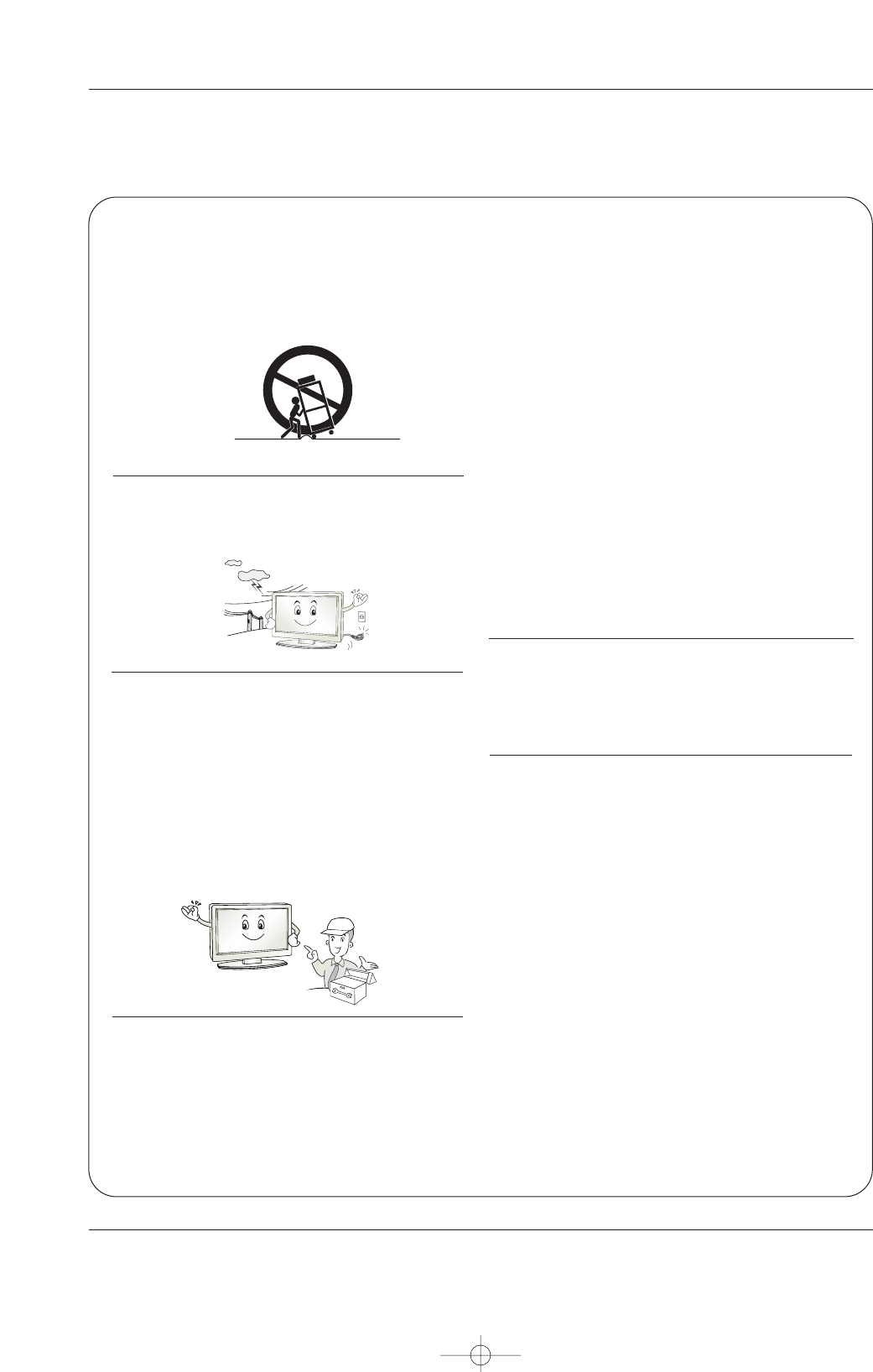
12. Use only with the cart, stand, tripod, bracket, or table
specified by the manufacturer, or sold with the apparatus.
When a cart is used, use caution when moving the
cart/apparatus combination to avoid injury from tip-over.
13. Unplug this apparatus during lightning storms or when
unused for long periods of time.
14. Refer all servicing to qualified service personnel.
Servicing is required when the apparatus has been dam-
aged in any way, such as power-supply cord or plug is dam-
aged, liquid has been spilled or objects have fallen into the
apparatus, the apparatus has exposed to rain or moisture,
does not operate normally, or has been dropped.
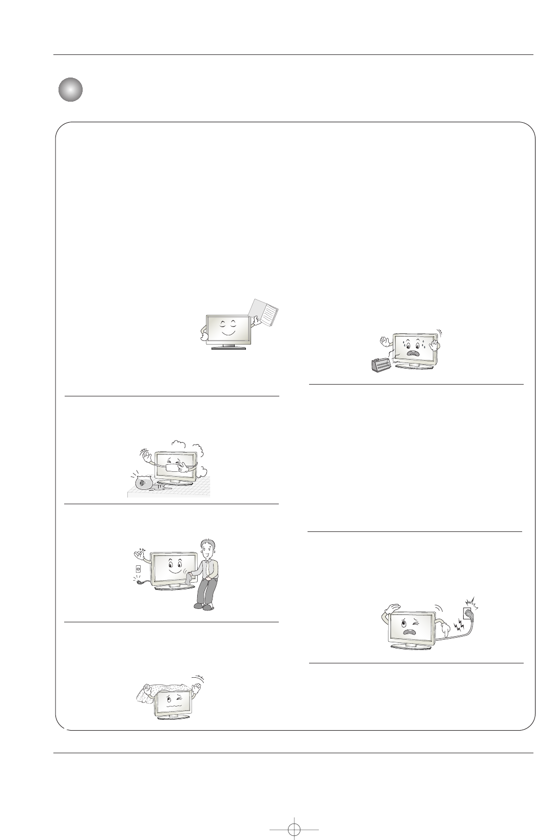
15. CAUTION concerning the Power Cord :
Most appliances recommend they be placed upon a dedi-
cated circuit; that is, a single outlet circuit which powers only
that appliance and has no additional outlets or branch cir-
cuits. Check the specification page of this owner's manual to
be certain.
Do not overload wall outlets. Overloaded wall outlets, loose
or damaged wall outlets, extension cords, frayed power
cords, or damaged or cracked wire insulation are dangerous.
Any of these conditions could result in electric shock or fire.
Periodically examine the cord of your
appliance, and if its appearance indicates damage or deteri-
oration, unplug it, discontinue use of the appliance, and have
the cord replaced with an exact replacement part by an
authorized servicer.
Protect the power cord from physical or mechanical abuse,
such as being twisted, kinked, pinched, closed in a door, or
walked upon. Pay particular attention to plugs, wall outlets,
and the point where the cord exits the appliance.
16. Outdoor Use Marking :
WARNING - To Reduce The Risk Of Fire Or Electric Shock,
Do Not Expose This Appliance To Rain Or Moisture.
17. Wet Location Marking :
Apparatus shall not be exposed to dripping or splashing and
no objects filled with liquids, such as vases, shall be placed
on the apparatus.
18. Any DATA saved on HDD may be lost or damaged, mak-
ing a back up copy of data is strongly recommended. The
manufacturer will NOT be responsible for any data loss or
damage.
PORTABLE CART WARNING
U514Aen 97/10/26 3:11 AM Page 4

Owner’s Manual 5
Contents
After reading this manual, keep it handy for future reference.
Warinig/Caution . . . . . . . . . . . . . . . . . . . . . . . . . . . . . . . . .2
Safety Instructions . . . . . . . . . . . . . . . . . . . . . . . . . . . . .2~3
Introduction
Accessories . . . . . . . . . . . . . . . . . . . . . . . . . . . .7
Controls . . . . . . . . . . . . . . . . . . . . . . . . . . . . . . .7
Connection Options . . . . . . . . . . . . . . . . . . . . . .8
Remote Control Key Functions . . . . . . . . . . . . . .9
Installation Instructions
Desktop Pedestal Installation . . . . . . . . . . . . . .10
External Equipment Connections
VCR Setup / Cable TV Setup . . . . . . . . . . . . . . . .11
External A/V Source Setup . . . . . . . . . . . . . . . .12
DVD Setup . . . . . . . . . . . . . . . . . . . . . . . . . . . .12
DTV Setup . . . . . . . . . . . . . . . . . . . . . . . . . . . .13
Monitor Out Setup . . . . . . . . . . . . . . . . . . . . . .14
PC Setup . . . . . . . . . . . . . . . . . . . . . . . . . .14~15
Basic Operation
Turning the monitor On . . . . . . . . . . . . . . . . . . .16
Volume Adjustment . . . . . . . . . . . . . . . . . . . . . .16
On-screen Menus Language Selection . . . . . . .16
On Screen Menus Selection and Adjustment . . .17
Picture Adjustment
APC (Auto Picture Control) . . . . . . . . . . . . . . . .18
XD . . . . . . . . . . . . . . . . . . . . . . . . . . . . . . . . . .18
Color Temperature Control . . . . . . . . . . . . . . . .18
ACM . . . . . . . . . . . . . . . . . . . . . . . . . . . . . . . . .19
sRGB . . . . . . . . . . . . . . . . . . . . . . . . . . . . . . . .19
Manual Picture Control(Off option) . . . . . . . . . .19
Audio Adjustment
DASP (Digital Auto Sound Processing) . . . . . . .20
BBE . . . . . . . . . . . . . . . . . . . . . . . . . . . . . . . . .20
AVL (Auto Volume Leveler) . . . . . . . . . . . . . . . .21
Manual Sound Control (Off option) . . . . . . . . . .21
TV speaker Setup . . . . . . . . . . . . . . . . . . . . . . .21
Time Setting
Clock Setup . . . . . . . . . . . . . . . . . . . . . . . . . . .22
On/Off Timer Setup . . . . . . . . . . . . . . . . . . . . .22
Auto Off / Sleep Timer . . . . . . . . . . . . . . . . . . .23
Optional Features
Key Lock . . . . . . . . . . . . . . . . . . . . . . . . . . . . .24
ISM (Image Sticking Minimization) Method . . . .24
Low Power . . . . . . . . . . . . . . . . . . . . . . . . . . . .25
XD Demo . . . . . . . . . . . . . . . . . . . . . . . . . . . . .25
OSD Rotate . . . . . . . . . . . . . . . . . . . . . . . . . . .25
Screen Adjustment
Auto Adjustment . . . . . . . . . . . . . . . . . . . . . . .26
Setting Picture Format . . . . . . . . . . . . . . . . . . .26
Manual Configure . . . . . . . . . . . . . . . . . . . . . .26
Selecting VGA/XGA Mode . . . . . . . . . . . . . . . .27
Picture size Zoom . . . . . . . . . . . . . . . . . . . . . .27
Screen Position . . . . . . . . . . . . . . . . . . . . . . . .27
Cinema Mode Setup . . . . . . . . . . . . . . . . . . . . .27
NR (Noise Reduction) . . . . . . . . . . . . . . . . . . . .28
Initializing (Reset to original factory value) . . . . .28
Split Zoom . . . . . . . . . . . . . . . . . . . . . . . . . . . .28
Lock Adjustment
Setting Up Your password . . . . . . . . . . . . . . . . .29
Lock System . . . . . . . . . . . . . . . . . . . . . . . . . . .29
Set Password . . . . . . . . . . . . . . . . . . . . . . . . . .30
MPAA(Movie pating) . . . . . . . . . . . . . . . . . . . . .30
Age block . . . . . . . . . . . . . . . . . . . . . . . . . . . . .31
Content block . . . . . . . . . . . . . . . . . . . . . . . . . .31
Aux. Block . . . . . . . . . . . . . . . . . . . . . . . . . . . .32
Appendix
External Control Device Setup . . . . . . . . . . . . . . . . . .33~38
IR Codes . . . . . . . . . . . . . . . . . . . . . . . . . . . . . . . . .39~40
Troubleshooting Checklist . . . . . . . . . . . . . . . . . . . . . . . .41
Product Specifications . . . . . . . . . . . . . . . . . . . . . . . . . . .42
Warranty . . . . . . . . . . . . . . . . . . . . . . . . . . . . . . 43~44
Contents
Contents
U514Aen 97/10/26 3:11 AM Page 5

6 Plasma Monitor
Introduction
What is a Plasma Display Panel (PDP)?
A plasma display panel is the latest display technology and the best way to achieve flat panel displays with excellent image quality
and large screen sizes that are easily viewable. The PDP can be thought of as a descendant of the neon lamp and it can be also
be viewed as a series of fluorescent lamps.
How does it work?
PDP is an array of cells, known as pixels, which are comprised of 3 sub pixels, corresponding to the colors red, green, and blue.
Gas in a plasma state is used to react with phosphors in each sub-pixel to produce colored light (red, green, or blue). These phos-
phors are the same types used in Cathode Ray Tube (CRT) devices such as televisions and common computer monitors.
You get the rich, dynamic colors that you expect. Each sub-pixel is individually controlled by advanced electronics to produce over
16 million different colors. All of this means that you get perfect images that are easily viewable in a display that is less than 5
inches thick.
160° - Wide angle range of vision
Your flat panel plasma screen offers an exceptionally broad viewing angle -- over 160 degrees. This means that the display is
clear and visible to viewers anywhere in the room who can see the screen.
Wide Screen
The screen of the Plasma Display is so wide that your viewing experience is as if you are in a theater.
Multimedia
Connect your plasma display to a PC and you can use it for conferencing, games, and Internet browsing. The Picture-in-Picture
feature allows you to view your PC and video images simultaneously.
Versatile
The light weight and thin size makes it easy to install your plasma display in a variety of locations where conventional monitors will
not fit.
The PDP Manufacturing Process: a few minute colored dots may be present on the PDP screen
The PDP (Plasma Display Panel), which is the display device of this product is composed of 0.9 to 2.2 million cells. A few cell
defects will normally occur in the PDP manufacturing process. Several tiny, minute colored dots visible on the screen should be
acceptable. This also occurs in other PDP manufacturers' products. The tiny dots appearing does not mean that this PDP is defec-
tive. Thus a few cell defects are not sufficient cause for the PDP to be exchanged or returned. Our production technology mini-
mizes these cell defects during the manufacture and operation of this product.
Introduction
Introduction
U514Aen 97/10/26 3:11 AM Page 6
Owner’s Manual 7
Introduction
Ensure that the following accessories are included with your plasma display. If an accessory is missing, please contact the dealer
where you purchased the product.
Accessories
Accessories
Owner’s Manual
1.5V
1.5V
Batteries Power Cord
POWER
MUTE
INPUT
MULTIMEDIA
MTS/
EXIT
VOL
ENTER
123
456
789
0
VOL
ARC
MENU
APC
DASP
SPLIT ZOOM
SLEEP
MEMORY/
ERASE/
REVIEW/
FCR/
A.PROG/
PLAY
STILL
STOP
RECORD
REW
FF
POWER
Remote Control
Controls
Controls
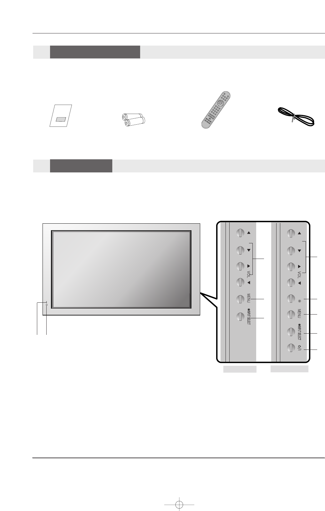
Front Panel Controls
Front Panel Controls
- This is a simplified representation of front panel.
Here shown may be somewhat different from your Monitor.
OK
1. Remote Control Sensor
2. Power Standby Indicator
Illuminates red in standby mode, Illuminates green when the
Set is turned on.
3. VOLUME (FF,GG) Buttons
EE, DDButtons
4. OK Button
5. MENU Button
6. INPUT SELECT Button
7. Power Button
Switches the set on from standby or off to standby.
5
6
7
4
3
2
1
3
5
6
42PM1M 42/50PM3MV
U514Aen 97/10/26 3:11 AM Page 7
8 Plasma Monitor
Introduction
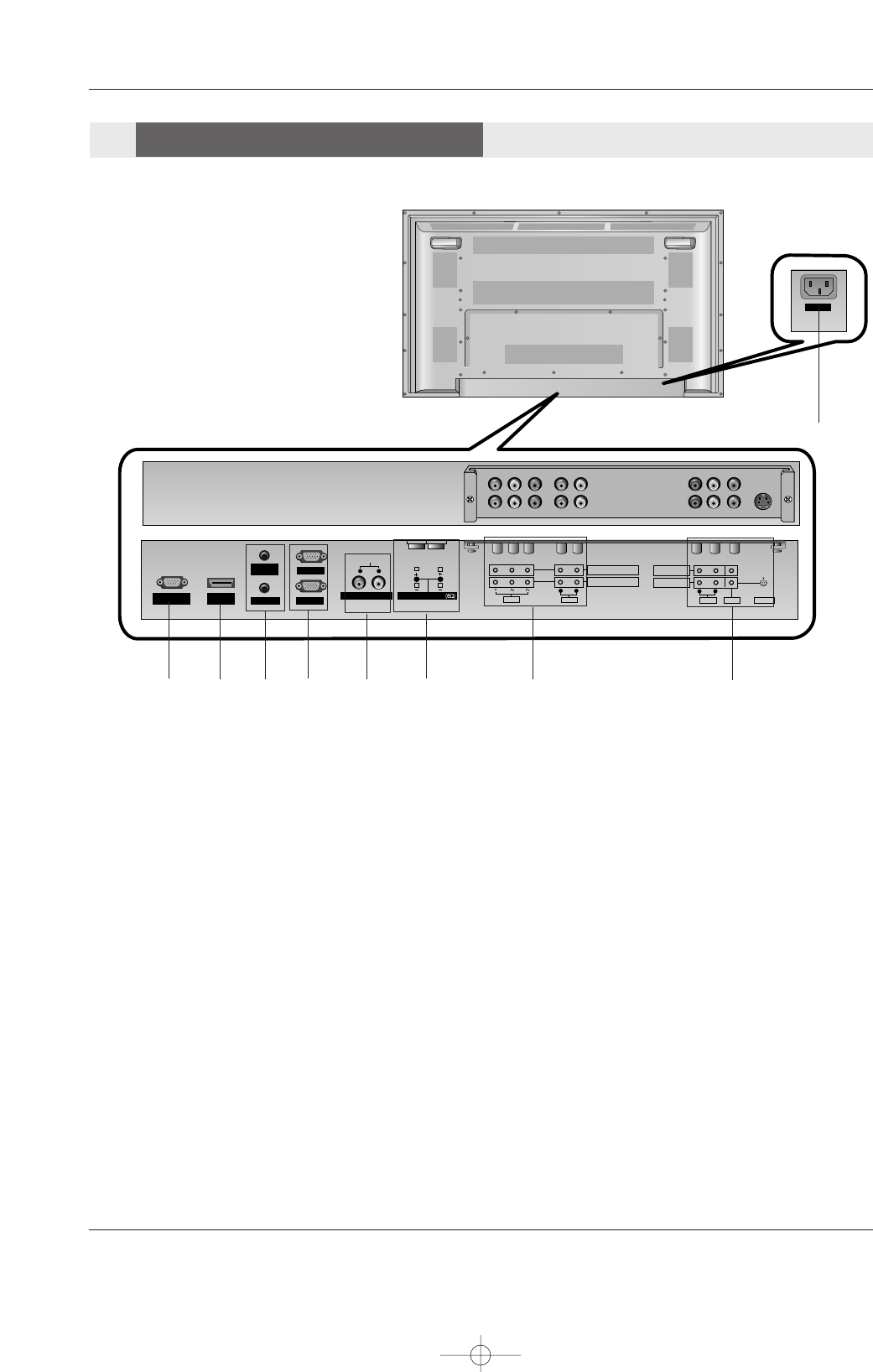
- Connection panels shown may be somewhat different from your Monitor.
AC INPUT
RS-232C INPUT
(CONTROL/SERVICE)
AUDIO
LR
REMOTE
CONTROL
AUDIO INPUT
RGB INPUT
HDMI/
DVI(VIDEO)
RGB OUTPUT
S-VIDEO
COMPONENT INPUT 2
COMPONENT INPUT 1
AUDIO
VIDEO
RL
AUDIO VIDEO
R
MONITOR OUT
A/V INPUT
LMONO
EXTERNAL SPEAKER
RL
VARIABLE AUDIO OUT
15
2 3 78
9
1. RS-232C INPUT(CONTROL/SERVICE) PORT
Connect to the RS-232C port on a PC.
2. HDMI/DVI (VIDEO)
Connect a HDMI signal to this jack. Or connect a DVI(Video)
signal.
3. REMOTE CONTROL / AUDIO INPUT (for RGB, DVI)
4. RGB INPUT
Connect the set output connector from a PC to the
appropriate input port.
RGB OUTPUT
You can watch the RGB signal on another set, connect RGB
OUTPUT to another set’s PC input port.
5. VARIABLE AUDIO OUTPUT
6. EXTERNAL SPEAKER (8 ohm output)
Connect to optional external speaker(s).
* For further information, refer to ‘Speaker & Speaker
Stand’manual.
7. COMPONENT INPUT
Connect a component video/audio device to these jacks.
8. VIDEO/AUDIO IN/OUT SOCKETS
Connect the video/audio out sockets of external equipment
to these sockets.
S-VIDEO/AUDIO IN SOCKETS
Connect the S-VIDEO out socket of an VCR to the S-VIDEO
socket.
Connect the audio out sockets of the VCR to the audio sock-
ets as in AV.
MONITOR OUT
Connect a second Set or monitor.
9. POWER CORD SOCKET
This the set operates on an AC power. The voltage is indicat-
ed on the Specifications page. Never attempt to operate the
set on DC power.
46
Connection Options
Connection Options
U514Aen 97/10/26 3:11 AM Page 8
Owner’s Manual 9
Introduction
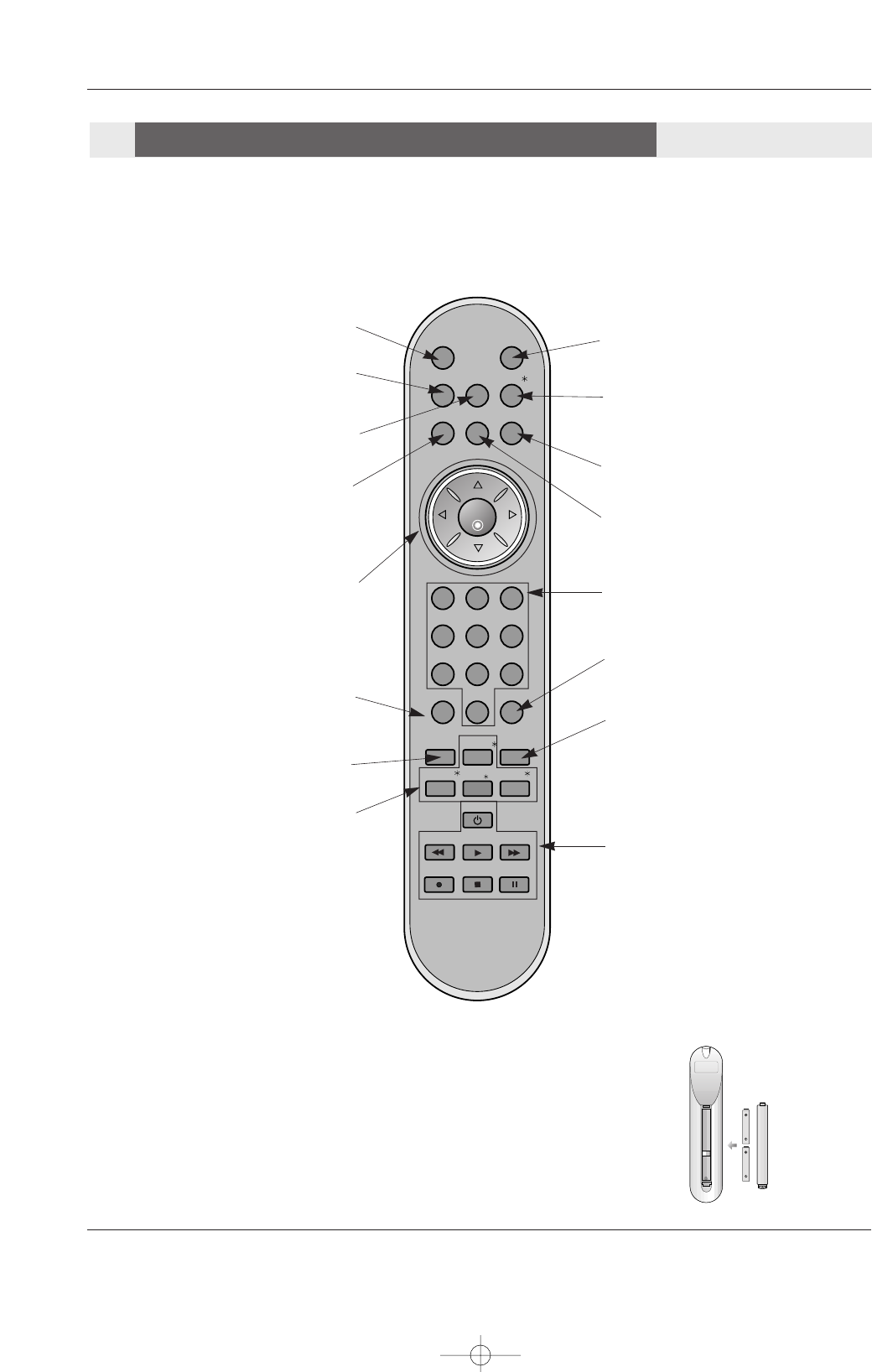
Installing Batteries
• Open the battery compartment cover on the back side and install the batteries
matching correct polarity (+ with +, - with -).
• Install two 1.5V AAA batteries. Don’t mix old or used batteries with new ones.
Replace cover.
POWERMUTE
INPUT
MULTIMEDIA
MTS/
EXIT
VOL
ENTER
123
456
789
0
VOL
ARC
MENU
APC
DASP
SPLIT ZOOM
SLEEP
MEMORY/
ERASE/
REVIEW/
FCR/
A.PROG/
PLAY
STILL
STOP
RECORD
REW FF
POWER
MUTE
Switches the sound on or off.
INPUT
Selects source: RGB,HDMI,
Component or Video mode.
MULTIMEDIA
Selects: RGB,HDMI and Component
input sources.
MENU
Brings up the main menu to the screen.
VOLUME UP/DOWN
Increases/decreases the sound level.
Selects a menu item.
EE / DD
Selects menu options.
ENTER
Accepts your selection or displays the
current mode.
POWER
Turns your Monitor on or off.
Not functional
EXIT
Clears all on-screen displays and returns
to monitor viewing from any menu.
DASP
Selects the sound appropriate for the pro-
gram's character.
Not functional
ARC
Changes the picture format.
VCR/DVD BUTTONS
Control some video cassette recorders or
DVD player ("RECORD" button is not
available for DVD player).
APC
Adjusts the factory preset picture according
to the room.
Not functional
SPLIT ZOOM
Enlarges the picture with regular ration.
SLEEP
Sets the sleep timer.
- When using the remote control, aim it at the remote control sensor on the Monitor.
- Under certain conditions such as if the remote IR signal is interrupted, the remote control may not function. Press the key again
as necessary.
Remote Control Key Functions
Remote Control Key Functions
U514Aen 97/10/26 3:11 AM Page 9
10 Plasma Monitor
Installation Instructions
Installation Instructions
Installation Instructions
GROUNDING
Ensure that you connect the earth ground wire to prevent possible
electric shock. If grounding methods are not possible, have a qualified
electrician install a separate circuit breaker. Do not try to ground the
unit by connecting it to telephone wires, lightening rods, or gas pipes.
Power
Supply
Short-circuit
Breaker
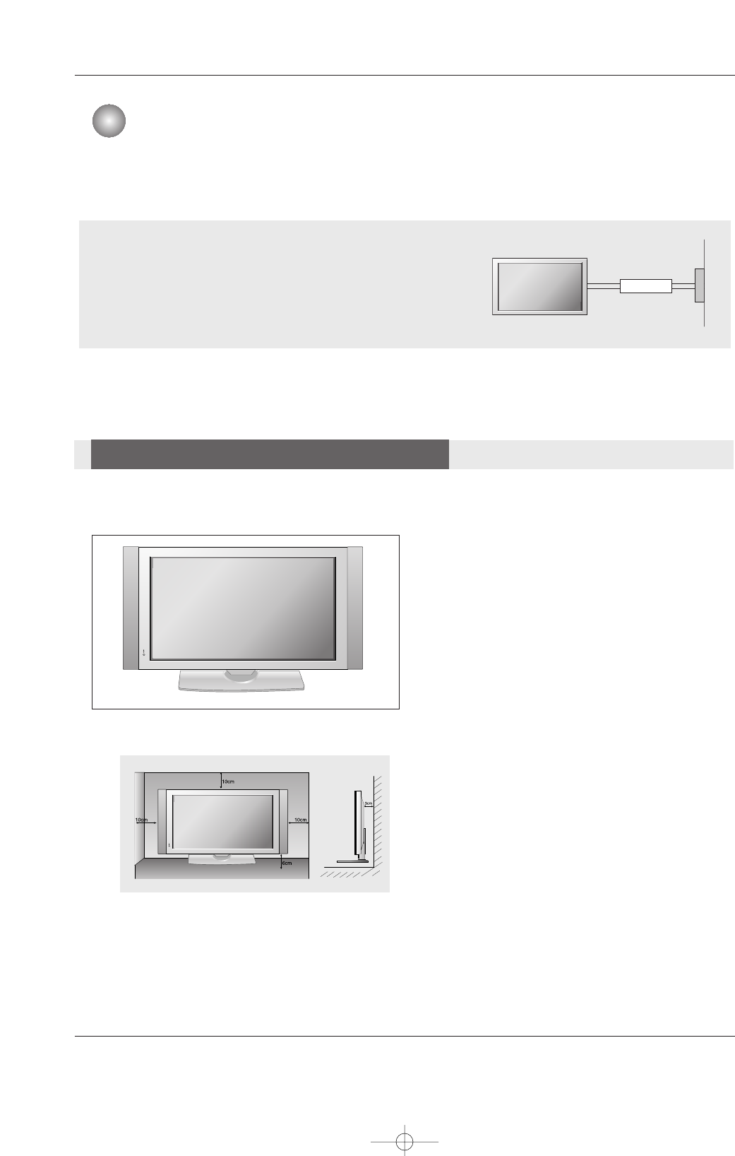
Desktop Pedestal Installation
Desktop Pedestal Installation
•For proper ventilation, allow a clearance of
4” on each side and the top, 2.36” on the
bottom, and 2” from the wall. Detailed
installation instructions are included in the
optional Desktop Stand Installation.
•Speakers shown are optional, and are
shown for example only.
•Pedestal mount minimum allowable
clearances for adequate ventilation.
U514Aen 97/10/26 3:11 AM Page 10
Owner’s Manual 11
External Equipment Connections
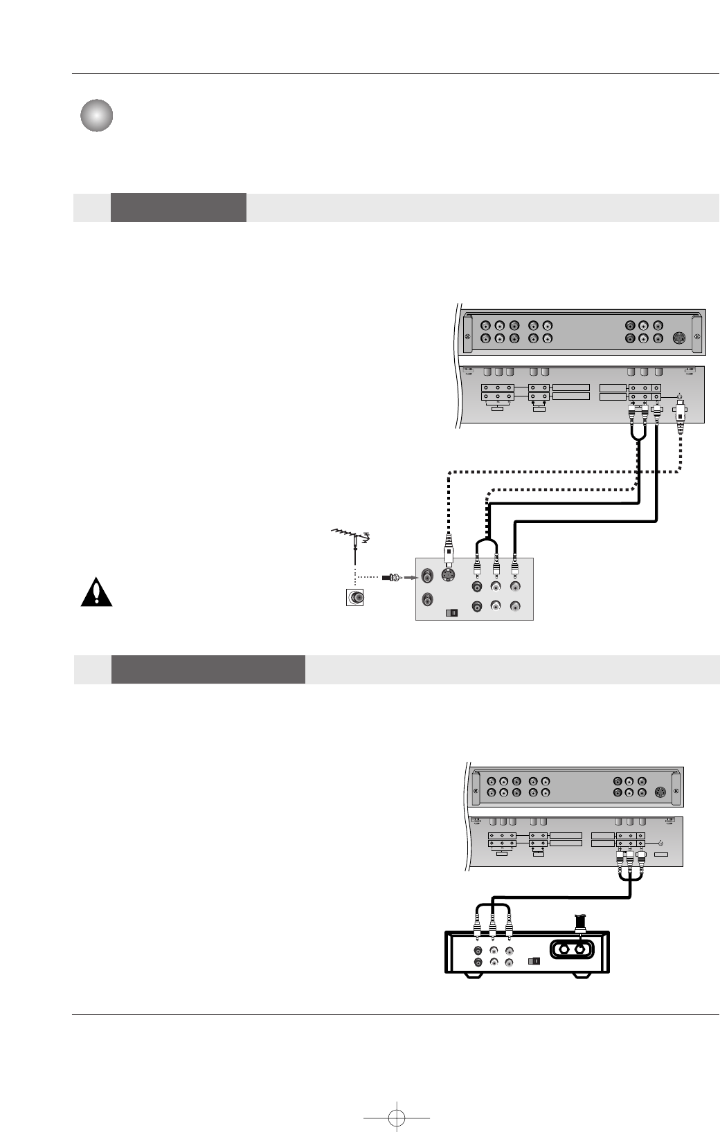
NOTE: All cables shown are not included with the monitor.
- To avoid picture noise (interference), leave an adequate distance between the VCR and monitor.
- Use the ISM Method (on the Special menu) feature to avoid having a fixed image remain on the screen for a long period of
time. Typically a frozen still picture from a VCR. If the 4:3 picture format is used; the fixed images on the sides of the screen
may remain visible on the screen.
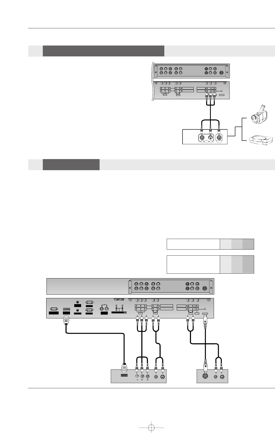
Connection Option
1. Connect the audio and video cables from the
VCR's output jacks to the set input jacks, as
shown in the figure.
When connecting the set to VCR, match the
jack colors (Video = yellow, Audio Left = white,
and Audio Right = red).
If you connect an S-VIDEO output from VCR to
the S-VIDEO input, the picture quality is
improved; compared to connecting a regular
VCR to the Video input.
2. Insert a video tape into the VCR and press
PLAY on the VCR. (Refer to the VCR owner’s
manual.)
3. Select the input source with using the INPUT
button on the remote control.
Do not connect to both Video and S-
Video at the same time. In the event
that you connect both Video and the
S-Video cables, only the S-Video will
work.
AUDIO
VARIABLE
AUDIO OUT
S-VIDEO
COMPONENT INPUT 2
COMPONENT INPUT 1
AUDIO
VIDEO
RL
AUDIO VIDEO
R
MONITOR OUT
A/V INPUT
LMONO
S-VIDEO OUT
IN
(R) AUDIO (L) VIDEO
34
OUTPUT
SWITCH
ANT OUT
ANT IN
- After subscribing to a cable TV service from a local provider and installing a converter, you can watch cable TV programming.
The set cannot display TV programming unless a TV tuner device or cable TV converter box is connected to the set.
- For further information regarding cable TV service, contact your local cable TV service provider(s).
Connection Option
1. Connect the audio and video cables from the Cable Box's output
jacks to the set input jacks, as shown in the figure.
When connecting the set to a Cable Box, match the jack colors
(Video = yellow, Audio Left = white, and Audio Right = red).
2. Select the input source with using the INPUT button on the
remote control.
3. Select your desired channel with the remote control for cable
box.
AUDIO
VARIABLE
AUDIO OUT
S-VIDEO
COMPONENT INPUT 2
COMPONENT INPUT 1
AUDIO
VIDEO
RL
AUDIO VIDEO
R
MONITOR OUT
A/V INPUT
LMONO
TV
VCR RF Cable
(R) AUDIO (L) VIDEO
34
OUTPUT
SWITCH
VCR
Cable Box
External Equipment Connections
External Equipment Connections
VCR Stup
VCR Stup
Cable TV Setup
Cable TV Setup
U514Aen 97/10/26 3:11 AM Page 11
12 Plasma Monitor
External Equipment Connections
•Component Input ports
To get better picture quality, connect a DVD player to the compo-
nent input ports as shown below.
How to connect
Connect the audio and video cables from the external
equipment's output jacks to the set input jacks, as shown in
the figure.
When connecting the set to external equipment, match the
jack colors (Video = yellow, Audio Left = white, and Audio
Right = red).
How to use
1. Select the input source with using the INPUT button on the
remote control.
2. Operate the corresponding external equipment. Refer to
external equipment operating guide.
Component ports
on the TV Y PBPR
Video output ports
on DVD player
Y
Y
Y
Y
Pb
B-Y
Cb
PB
Pr
R-Y
Cr
PR
How to connect
1. Connect the DVD video outputs (Y, PB, PR) to the COMPONENT (Y, PB, PR) INPUT or HDMI INPUT jacks on the set and con-
nect the DVD audio outputs to the AUDIO INPUT jacks on the set, as shown in the figure.
2. If your DVD only has an S-Video output jack, connect this to the S-VIDEO input on the set and connect the DVD audio outputs
to the AUDIO INPUT jacks on the set, as shown in the figure.
NOTE: If your DVD player does not have component video output, use S-Video.
How to use
1. Turn on the DVD player, insert a DVD.
2. Use the INPUT or MULTIMEDIA button on the remote control to select Component 1 or Component 2. (If connected to S-
VIDEO, select the Video external input source.)
3. Refer to the DVD player's manual for operating instructions.
AUDIO
VARIABLE
AUDIO OUT
S-VIDEO
COMPONENT INPUT 2
COMPONENT INPUT 1
AUDIO
VIDEO
RL
AUDIO VIDEO
R
MONITOR OUT
A/V INPUT
LMONO
RL
AUDIO VIDEO
RS-232C INPUT
(CONTROL/SERVICE)
AUDIO AUDIO
LR
REMOTE
CONTROL
AUDIO INPUT
RGB INPUT
HDMI/
DVI(VIDEO)
RGB OUTPUT
S-VIDEO
COMPONENT INPUT 2
COMPONENT INPUT 1
AUDIO
VIDEO
RL
AUDIO VIDEO
R
MONITOR OUT
A/V INPUT
L
MONO
VARIABLE
AUDIO OUT
EXTERNAL SPEAKER
RL
BR
(R) AUDIO (L) (R) AUDIO (L)
S-VIDEO
HDMI-DTV OUTPUT
DVD
or
Camcorder
Video Game Set
External
External A/V Source Setup
A/V Source Setup
DVD Setup
DVD Setup
U514Aen 97/10/26 3:11 AM Page 12
Owner’s Manual 13
External Equipment Connections
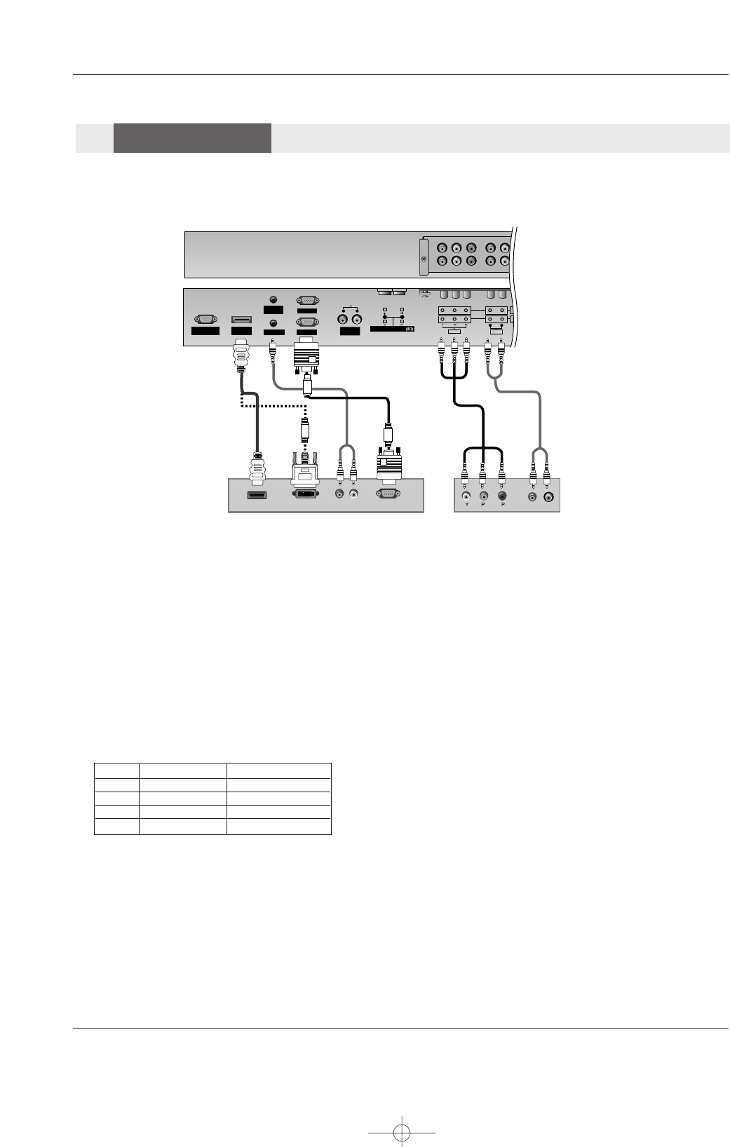
How to connect
Use the set’s COMPONENT (Y, PB, PR) INPUT, RGB or HDMI jack for video
connections, depending on your set-top box connector. Then, make the corre-
sponding audio connections.
How to use
1. Turn on the digital set-top box. (Refer to the owner’s manual for the digital set-
top box.)
2. Use INPUT or MULTIMEDIA on the remote control to select Component 1,
Component 2, RGB or HDMI source.
- To watch digitally broadcast programs, purchase and connect a digital set-top box.
RS-232C INPUT
(CONTROL/SERVICE)
AUDIO AUDIO
LR
REMOTE
CONTROL
AUDIO INPUT
RGB INPUT
HDMI/
DVI(VIDEO)
RGB OUTPUT
CO
CO
AUDIO
VIDEO
RL
VARIABLE
AUDIO OUT
EXTERNAL SPEAKER
RL
RGB-DTV OUTPUT
(R) AUDIO (L)
DVI-DTV OUTPUT
HDMI OUTPUT
BR
(R) AUDIO (L)
Digital Set-top Box
or
or
Signal
480i
480p
720p
1080i
Component 1/2
Yes
Yes
Yes
Yes
RGB, HDMI
No
Yes
Yes
Yes
DTV
DTV Setup
Setup
U514Aen 97/10/26 3:11 AM Page 13
14 Plasma Monitor
External Equipment Connections
NOTE: All cables shown are not included with the Monitor
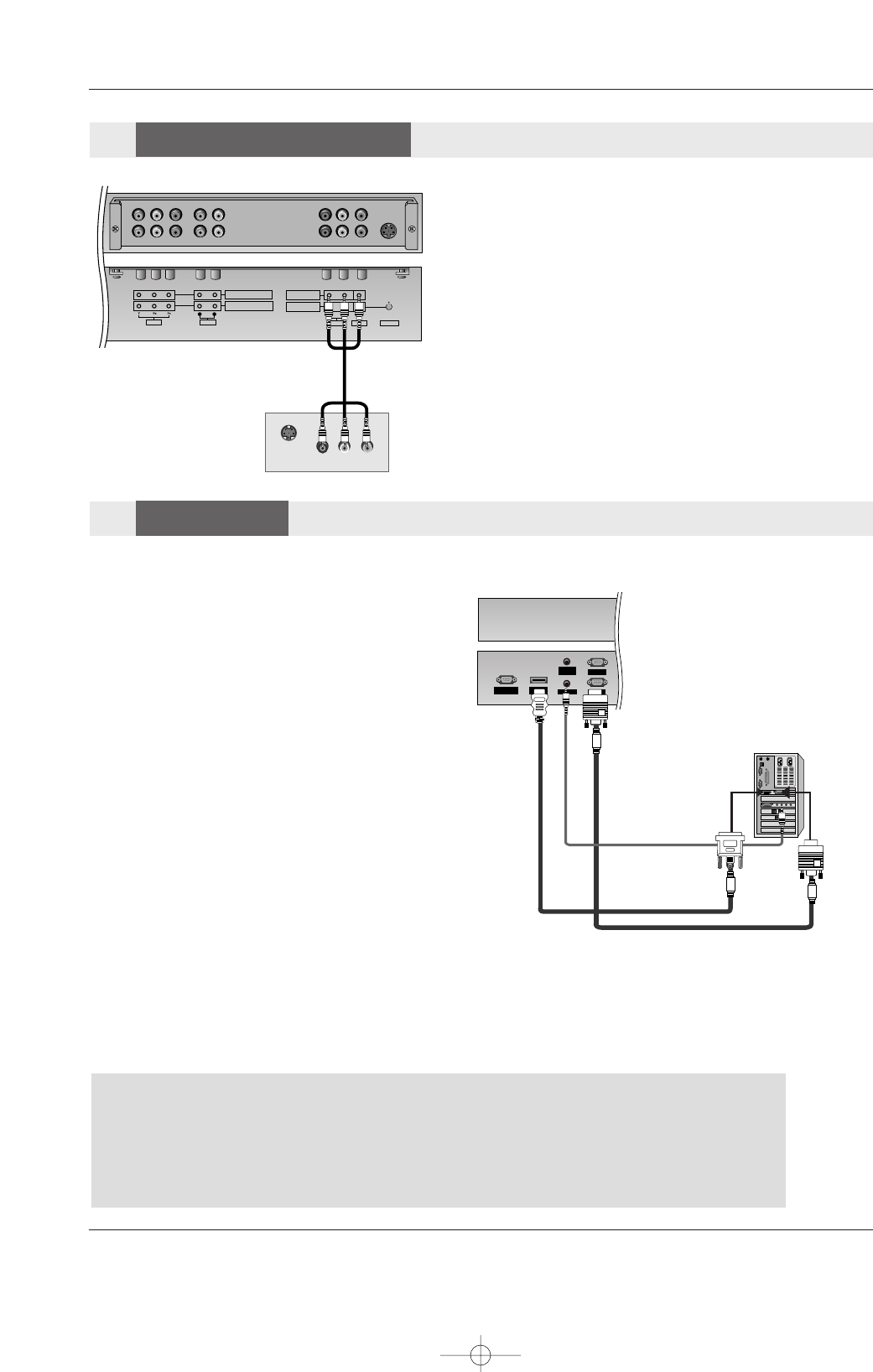
How to connect
1. To get the best picture quality, adjust the PC
graphics card to 640x 480, 60Hz.
2. Use the set’s RGB INPUT or HDMI/DVI (VIDEO)
INPUT port for video connections, depending on
your PC connector.
• If the graphic card on the PC does not output
analog and digital RGB simultaneously, connect
only one of either RGB INPUT or HDMI/DVI
(VIDEO) to display the PC on the set.
• If the graphic card on the PC does output analog
and digital RGB simultaneously, set the set to
either RGB or HDMI/DVI (VIDEO); (the other
mode is set to Plug and Play automatically by the
set.)
3. Then, make the corresponding audio connection. If
using a sound card, adjust the PC sound as
required.
RS-232C INPUT
(CONTROL/SERVICE)
AUDIO
REMOTE
CONTROL
AUDIO INPUT
RGB INPUT
VARIABLE
AUDIO OUT
HDMI/
DVI(VIDEO)
RGB OUTPUT
How to use
1. Turn on the PC and the set.
2. Turn on the display by pressing the POWER button on the set's remote control.
3. Use INPUT or MULTIMEDIA on the remote control to select RGB or HDMI source.
4. Check the image on your set. There may be noise associated with the resolution, vertical pattern, contrast or brightness in PC
mode. If noise is present, change the PC mode to another resolution, change the refresh rate to another rate or adjust the
brightness and contrast on the menu until the picture is clear. If the refresh rate of the PC graphic card can not be changed,
change the PC graphic card or consult the manufacturer of the PC graphic card.
PC
PC Setup
Setup
Note:
-Check the image on your TV. There may be noise associated with the resolution, vertical pattern, contrast or
brightness in PC mode. If noise is present, change the PC output to another resolution, change the refresh rate to
another rate or adjust the brightness and contrast on the VIDEO menu until the picture is clear. If the refresh rate
of the PC graphic card can not be changed, change the PC graphic card or consult the manufacturer of the PC
graphic card.
-When you use too long RGB-PC cable, there might be a noise on the screen. We recommend using under 5m of
the cable. It provides the best picture quality.
The set has a special signal output capability which allows you to
hook up a second set.
Connect the second set to the set’s MONITOR OUTPUT. See the
Operating Manual of the second set for further details regarding that
device’s input settings.
NOTE
• Component, RGB, HDMI input sources cannot be used for Monitor
out.
AUDIO
VARIABLE
AUDIO OUT
S-VIDEO
COMPONENT INPUT 2
COMPONENT INPUT 1
AUDIO
VIDEO
RL
AUDIO VIDEO
R
MONITOR OUT
A/V INPUT
LMONO
S-VIDEO IN
(R) AUDIO (L) VIDEO
Monitor Out
Monitor Out Setup
Setup
U514Aen 97/10/26 3:11 AM Page 14
Owner’s Manual 15
External Equipment Connections
Notes:
- Depending on the graphics card, DOS mode may not
work if a HDMI to DVI Cable is in use.
- Avoid keeping a fixed image on the screen for a long peri-
od of time. The fixed image may become permanently
imprinted on the screen. Use the Orbiter feature on the
ISM Method menu.
- When Source Devices connected with HDMI/DVI Input,
output PC Resolution(VGA, XGA), Position and Size
may not fit to Screen.
- When Source Devices connected with HDMI/DVI Input,
output TV SET Resolution(480p, 720p, 1080i) and SET
Display fit EIA/CEA-861-B Specification to Screen. If not,
refer to the Manual of HDMI/DVI Source Devices or con-
tact your service center.
- In case HDMI/DVI Source Devices is not connected
Cable or poor cable connection, "No signal" OSD dis-
play in HDMI/DVI Input. In case that Video Resolution is
not supported SET output in HDMI/DVI Source Devices,
"Invalid Format" OSD display. Refer to the Manual of
HDMI/DVI Source Devices or contact your service cen-
ter.
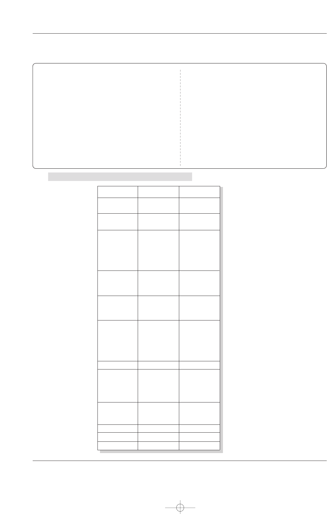
Resolution
640x350
720x400
640x480
848x480
800x600
Horizontal
Frequency(KHz)
Vertical
Frequency(Hz)
852x480
832x624
1024x768
1152x864
1152x870
1280x960
1280x1024
70.09
85.08
70.08
85.03
59.94
66.66
72.80
75.00
85.00
60.00
70.00
75.00
60.00
70.00
75.00
56.25
60.31
72.18
75.00
85.06
74.55
60.00
70.06
75.02
85.00
60.05
70.01
75.00
75.06
60.02
60.02
31.468
37.861
31.469
37.927
31.469
35.000
37.861
37.500
43.269
31.500
37.799
39.375
31.500
37.799
39.375
35.156
37.879
48.077
46.875
53.674
49.725
48.363
56.476
60.023
68.677
54.348
63.995
67.500
68.681
60.023
63.981
Monitor Display Specifications (RGB / HDMI mode )
U514Aen 97/10/26 3:11 AM Page 15
16 Plasma Monitor
Basic Operation
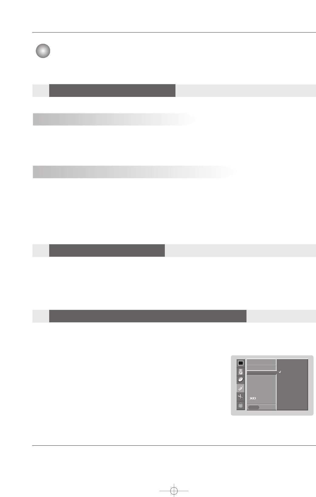
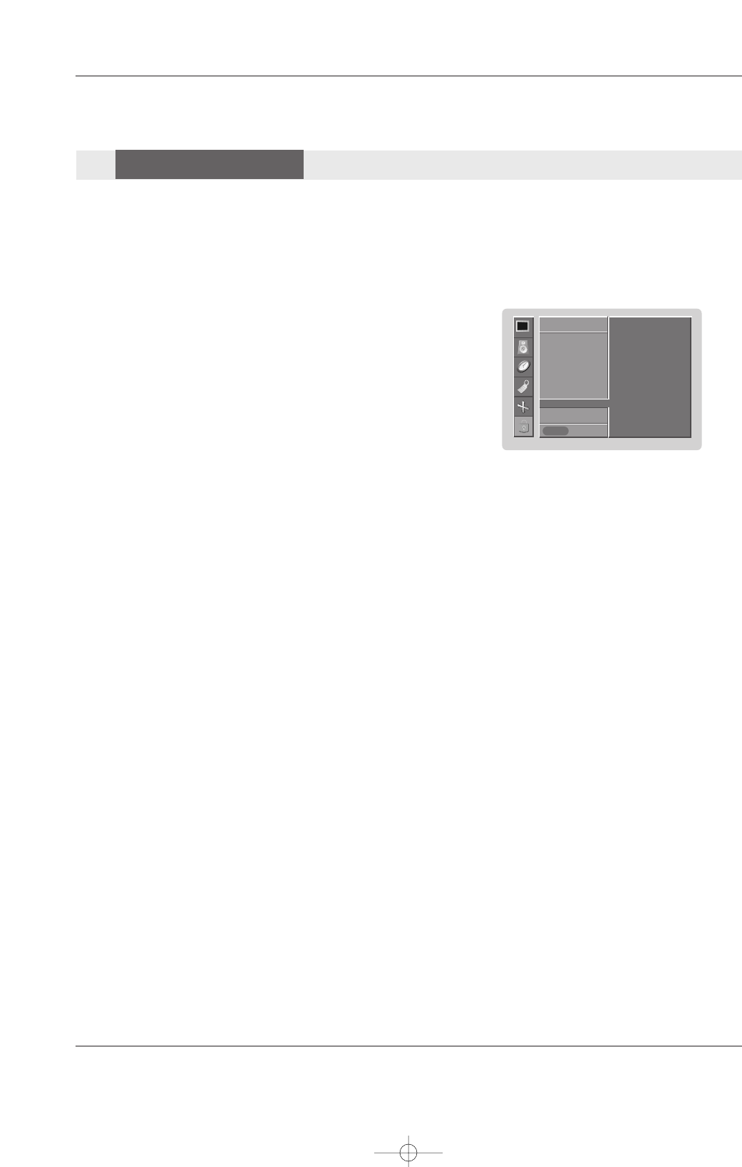
-The menus can be shown on the screen in the selected language. First select your language.
1. Press the MENU button and then use DD/ EEbutton to select the SPECIAL menu.
2. Press the GGbutton and then use DD/ EEbutton to select Language.
3. Press the GGbutton and then use DD/ EEbutton to select your desired language.
From this point on, the on-screen menus will be shown in the language of your choice.
4. Press the ENTER button to save.
NOTE
• If you intend to be away on vacation, disconnect the power plug from the wall power outlet.
Turning on the set just after installation
Turning on the set (power cord is still connected)
1. Connect power cord correctly, the set is switched to standby mode.
2. Press the rr/ I, INPUT SELECT button on the set or press the POWER, MULTIMEDIA, INPUT on the
remote control and then the set will switch on.
If the set was turned off with the remote control power button and the rr/ I button on the set.
•Press the rr/ I, INPUT SELECT button on the set or press the POWER, MULTIMEDIA, INPUT on the remote control
and then the set will switch on.
Basic Operation
Basic Operation
T
Turning the monitor On
urning the monitor On
On-screen Menus Language Selection
On-screen Menus Language Selection
1. Press the VOL DD/ EEbutton to adjust the volume.
2. If you want to switch the sound off, press the MUTE button.
3. You can cancel this function by pressing the MUTE or VOL DD/ EEbutton.
V
Volume
olume Adjustment
Adjustment
SPECIAL
Prev.
Input
Language GG
Key lock
ISM Method
Low power
Set ID
Caption / Text
Demo
OSD Rotate
SPECIAL
MENU
English
Español
Français
U514Aen 97/10/26 3:11 AM Page 16
Owner’s Manual 17
Basic Operation
1. Press the MENU button and then DD/ EEbutton to select each menu.
2. Press the GGbutton and then use DD / EE/ FF / GGbutton to display the available menus.
• Your monitor's OSD (On Screen Display) may differ slightly from what is shown in this manual.
On Screen Menus Selection and
On Screen Menus Selection and Adjustment
Adjustment
PICTURE
Prev.
APC
ACC
ACM
Contrast 80
Brightness 60
Color 50
Sharpness 50
PICTURE
MENU
SOUND
Prev.
DASP
BBE
AVL
Balance 0
Treble 50
Bass 50
TV speaker
SOUND
MENU
TIMER
Prev.
Clock
Off timer
On timer
Auto off
TIMER
MENU
AM
SPECIAL
Prev.
Input
Language
Key lock
ISM Method
Low power
Set ID
Caption / Text
Demo
OSD Rotate
SPECIAL
MENU
SCREEN
Prev.
Auto config.
Manual config.
VGA Mode
ARC
Zoom +/-
Position
Cinema
NR
Reset
SCREEN
MENU
LOCK
Prev.
Lock on/off
Set password
MPAA
Age block
Content block
Aux. block
LOCK
MENU
U514Aen 97/10/26 3:11 AM Page 17
18 Plasma Monitor
Picture Adjustment
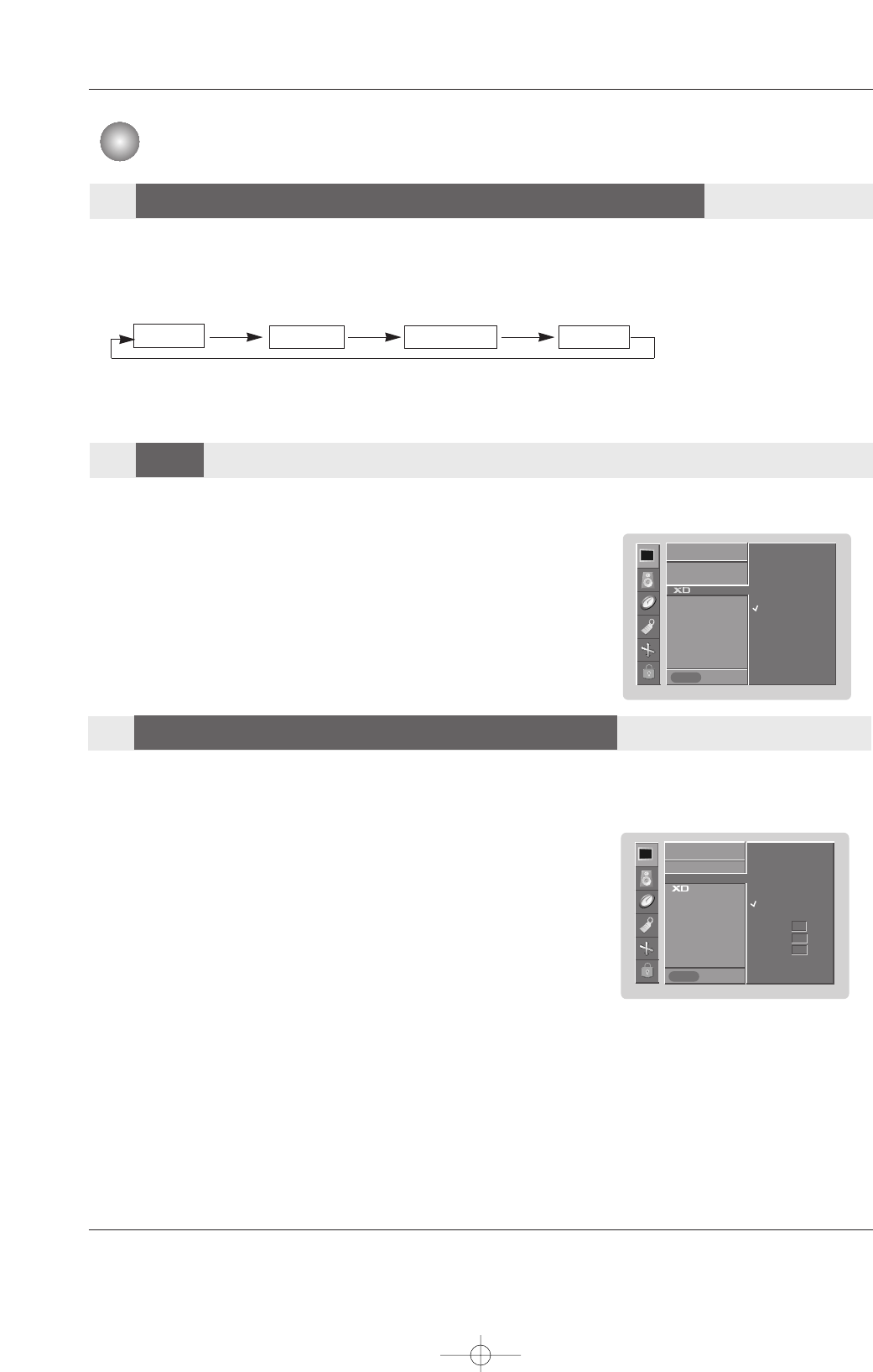
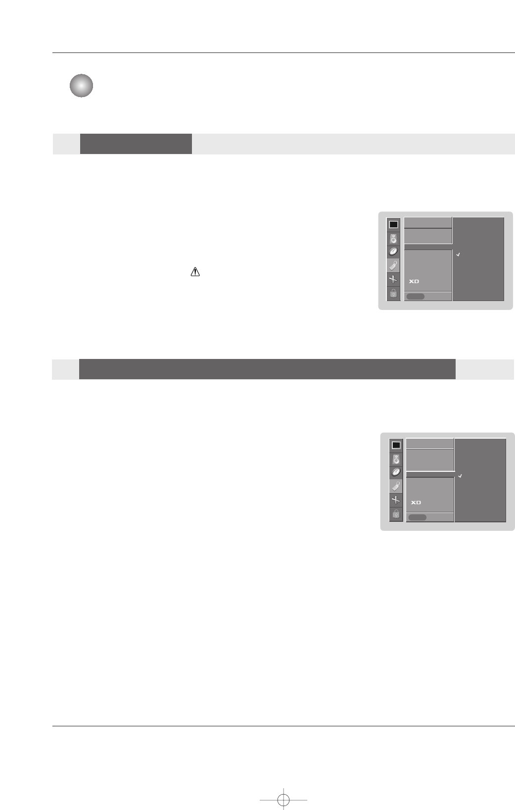
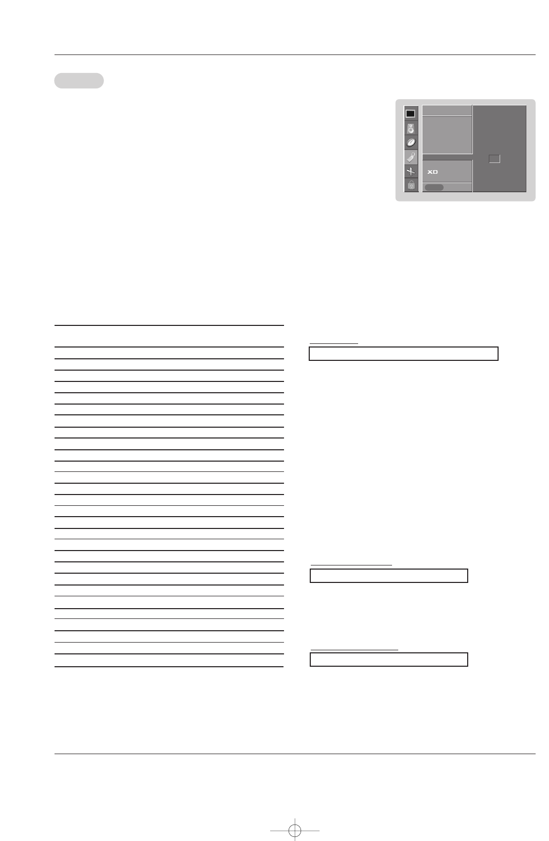
- XD is LG Electronic’s unique picture improving technology to display a real HD
source through an advanced digital signal processing algorithm.
- When selecting APC options (Clear, Optimum and Soft), XD is automatically
change to On.
- XD demo is not available for RGB (PC) and HDMI (PC) sources.
1. Press the MENU button and then use DD / EEbutton to select the PICTURE menu.
2. Press the GGbutton and then use DD / EEbutton to select XD.
3. Press the GGbutton and then use DD / EEbutton to set On or Off.
4. Press the ENTER button to save.
1. Press the APC button repeatedly to select the picture appearance setup option as shown below.
•You can also adjust APC in the PICTURE menu.
•Daylight, Optimum, and Night time settings are preset for good picture quality at the factory and cannot be
changed.
Daylight Optimum Night time Off
- APC adjusts the Monitor to the best picture appearance.
- If adjusting picture options (contrast, brightness, color, sharpness, or tint) manually, APC automatically
changes to Off.
Auto Color Temperature Control
- To initialize values (reset to default settings), select the Normal option.
1. Press the MENU button and then use DD / EEbutton to select the PICTURE menu.
2. Press the GGbutton and then use DD / EEbutton to select ACC .
3. Press the GGbutton and then use DD / EEbutton to select either: Cool (Preset),
Normal (Default), or Warm (Preset).
4. Press the ENTER button to save.
Manual Color Temperature Control (ACC set to Off option)
- You can adjust red, green, or blue to any color temperature you prefer.
1. Press the MENU button and then use DD / EEbutton to select the PICTURE menu.
2. Press the GGbutton and then use DD / EEbutton to select ACC .
3. Press the GGbutton and then use DD / EEbutton to select Off.
4. Press the GGbutton and then use DD / EEbutton to select Red, Green or Blue.
5. Use the FF / GGbutton to make appropriate adjustments.
• The adjustment range of Red, Green,and Blue is -40 ~ +40.
6. Press the ENTER button to save.
PICTURE
Prev.
APC
ACC
GG
ACM
Contrast 80
Brightness 60
Color 50
Sharpness 50
PICTURE
MENU
On
Off
PICTURE
Prev.
APC
ACC GG
ACM
Contrast 80
Brightness 60
Color 50
Sharpness 50
PICTURE
MENU
Cool
Normal
Warm
Off
Red 0
Green 0
Blue 0
Picture Adjustment
APC (Auto Picture Control)
APC (Auto Picture Control)
XD
XD
Color T
Color Temperature Control
emperature Control
U514Aen 97/10/26 3:11 AM Page 18
Owner’s Manual 19
Picture Adjustment
- You can adjust picture contrast, brightness, color and sharpness options to the
levels you prefer.
1. Press the MENU button and then use DD / EEbutton to select the PICTURE menu.
2. Press the GGbutton and then use DD / EEbutton to select the desired picture option
: RGB-DTV, HDMI-DTV : (Contrast,Brightness,Color,Sharpness).
: RGB-PC, HDMI-PC: (Contrast,Brightness,Color).
3. Press the GGbutton and then use FF / GGbutton to make appropriate adjustments.
4. Press the ENTER button to save.
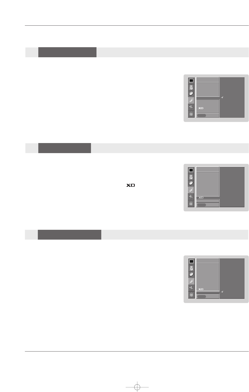
- If the Monitor is connected to external equipment using sRGB, set sRGB to On
to adjust for the color difference.
1. Press the MENU button and then use DD / EEbutton to select the PICTURE menu.
2. Press the GGbutton and then use DD / EEbutton to select sRGB.
3. Press the GGbutton and then use DD / EEbutton to select On or Off.
4. Press the ENTER button to save.
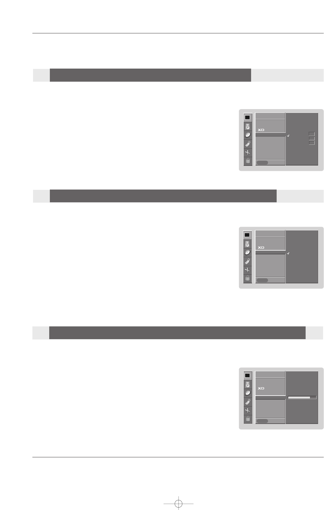
- Adjust the ACM to select the desired skin color option.
- This function works in the following mode:
VIDEO, COMPONENT1, 2, RGB-DTV, HDMI-DTV.
-It’s not available to use this function in
XD Off
mode.
1. Press the MENU button and then use DD / EEbutton to select the PICTURE menu.
2. Press the GGbutton and then use DD / EEbutton to select ACM.
3. Press the GGbutton and then use FF / GGbutton to make appropriate adjustments.
4. Press the ENTER button to save.
PICTURE
Prev.
APC
ACC
ACM GG
Contrast 80
Brightness 60
Color 50
Sharpness 50
Tint 0
PICTURE
MENU
Fleshtone 0
Greentone 0
Bluetone 0
PICTURE
Prev.
APC
ACC
sRGB GG
Contrast 80
Brightness 60
PICTURE
MENU
On
Off
PICTURE
Prev.
APC
ACC
ACM
Contrast 80 GG
Brightness 60
Color 50
Sharpness 50
PICTURE
MENU
ACM (Active Color Management)
ACM (Active Color Management)
sRGB (Only RGB-PC, DVI-PC Modes)
sRGB (Only RGB-PC, DVI-PC Modes)
Manual Picture Control (APC set to Off option)
Manual Picture Control (APC set to Off option)
U514Aen 97/10/26 3:11 AM Page 19
20 Plasma Monitor
Sound Adjustment
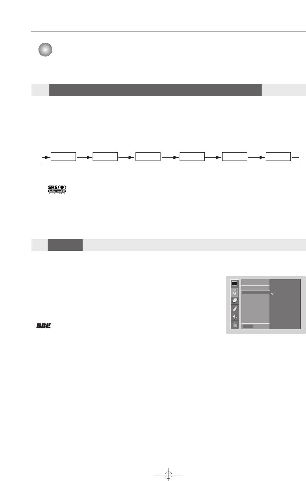
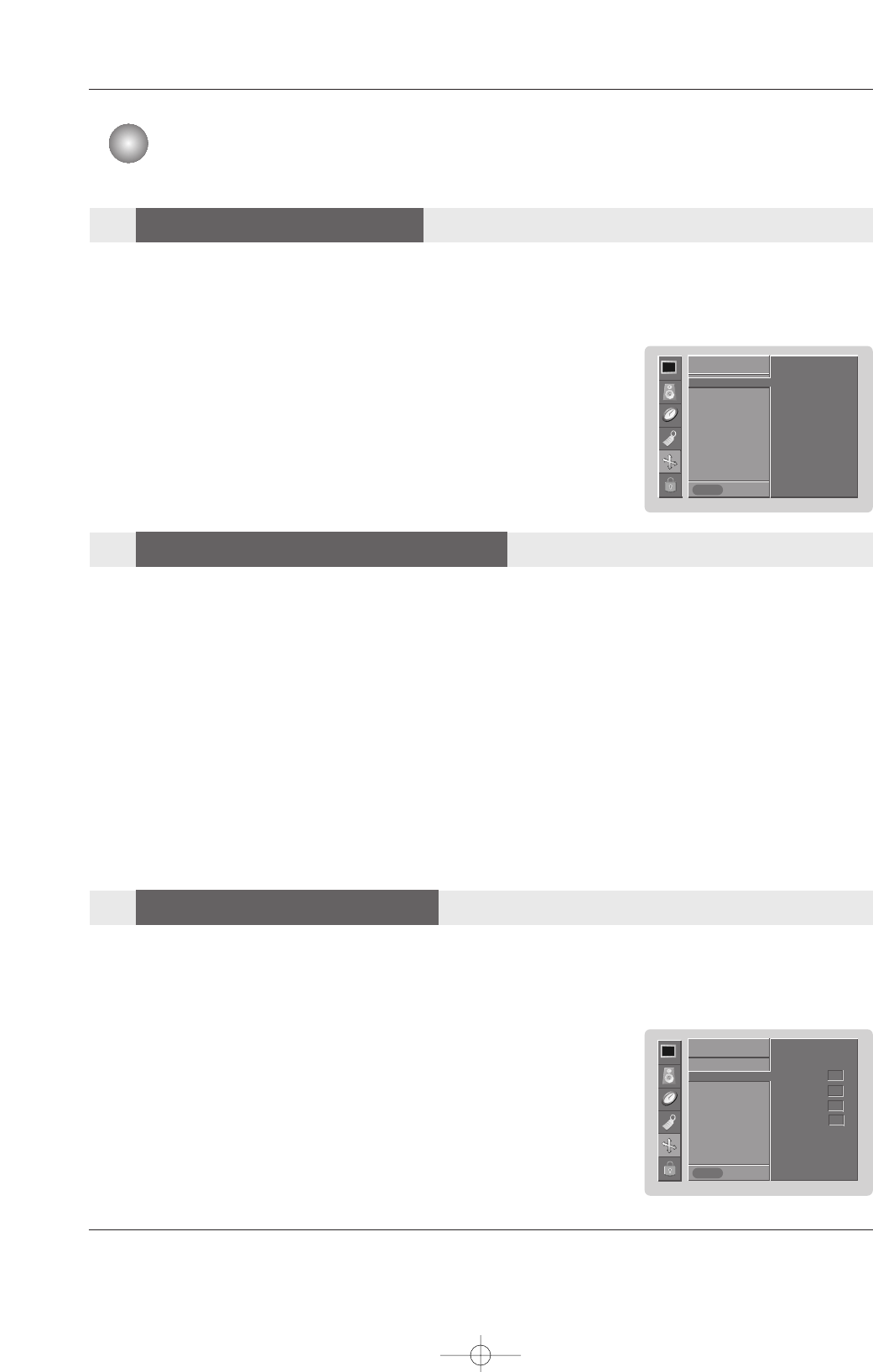
1. Press the DASP button repeatedly to select the appropriate sound setup as shown below.
•You can also adjust DASP in the SOUND menu.
•SRS TSXT, Flat, Music, Movie, and Sports are preset for good sound quality at the factory and cannot be changed.
•is a trademark of SRS Labs, Inc.
•TruSurround XT technology is incorporated under license from SRS Labs, Inc.
Flat Music Movie Sports OffSRS TSXT
- This function lets you enjoy the best sound without any special adjustment because the Monitor has the appro-
priate sound options based on the program content.
- If you adjust sound options (Treble and Bass) manually, DASP automatically changes to Off.
1. Press the MENU button and then use DD / EEbutton to select the SOUND menu.
2. Press the GGbutton and then use DD / EEbutton to select BBE.
3. Press the GGbutton and then use DD / EEbutton to select On or Off.
4. Press the ENTER button to save.
- BBE High Definition Sound restores clarity and presence for better speech
intelligibility and music realism.
•Manufactured under license from BBE Sound, Inc.
•Treble, Bass or BBE aren’t suitable for SRS TSXT mode.
SOUND
Prev.
DASP
BBE GG
AVL
Balance 0
Treble 50
Bass 50
TV speaker
SOUND
MENU
On
Off
Sound Adjustment
DASP
DASP (Digital
(Digital Auto Sound Processing)
Auto Sound Processing)
BBE
BBE
U514Aen 97/10/26 3:11 AM Page 20
Owner’s Manual 21
Sound Adjustment
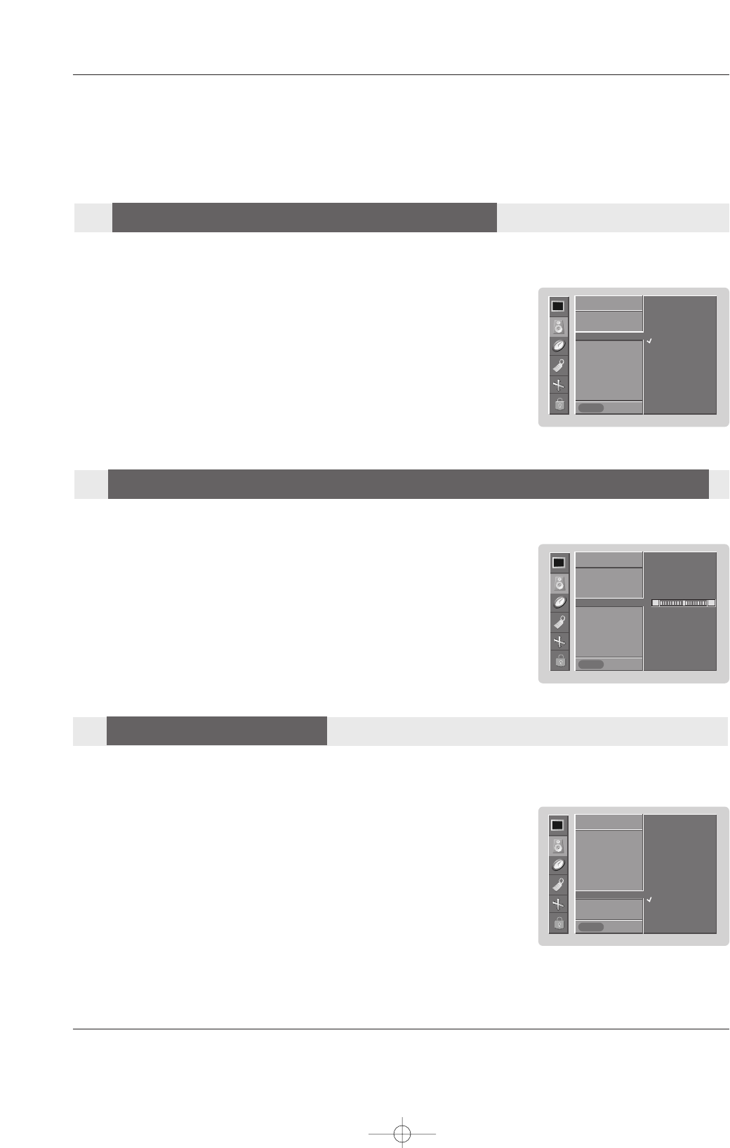
1. Press the MENU button and then use DD / EEbutton to select the SOUND menu.
2. Press the GGbutton and then use DD / EEbutton to select the desired sound option
(Balance,Treble,Bass).
3. Press the GGbutton and then use FF / GGbutton to make appropriate adjustments.
4. Press the ENTER button to save.
- You can adjust sound options Balance, Treble, and Bass to the levels you prefer.
- AVL maintains an equal sound level; even if you change channels.
1. Press the MENU button and then use DD / EEbutton to select the SOUND menu.
2. Press the GGbutton and then use DD / EEbutton to select AV L .
3. Press the GGbutton and then use DD / EEbutton to select On or Off.
4. Press the ENTER button to save.
1. Press the MENU button and then use DD / EEbutton to select the SOUND menu.
2. Press the GGbutton and then use DD / EEbutton to select TV speaker.
3. Press the GGbutton and then use DD / EEbutton to select On or Off.
4. Press the ENTER button to save.
- You can adjust internal speaker status.
- If you want to use your external hi-fi stereo system, turn off the internal speakers of the set.
SOUND
Prev.
DASP
BBE
AVL GG
Balance 0
Treble 50
Bass 50
TV speaker
SOUND
MENU
On
Off
SOUND
Prev.
DASP
BBE
AVL
Balance 0 GG
Treble 50
Bass 50
TV speaker
SOUND
MENU
L R
SOUND
Prev.
DASP
BBE
AVL
Balance 0
Treble 50
Bass 50
TV speaker GG
SOUND
MENU
On
Off
A
AVL
VL (Auto V
(Auto Volume Leveler)
olume Leveler)
Manual Sound Control (
Manual Sound Control (DASP
DASP Off
Off option and balance)
option and balance)
TV speaker Setup
TV speaker Setup
U514Aen 97/10/26 3:11 AM Page 21
22 Plasma Monitor
Time Setting
- Timer function operates only if current time has been set.
- Off-Timer function overrides On-Timer function if they are set both set to the same time.
- The Monitor must be in standby mode for the On-Timer to work.
- If you do not press any button within 2 hours after the Monitor turns on with the On Timer function, the Monitor will automatically
revert to standby mode.
1. Press the MENU button and then use DD / EEbutton to select the TIMER menu.
2. Press the GGbutton and then use DD / EEbutton to select Off timer or On timer.
3. Press the GGbutton and then use DD / EEbutton to select On.
• To cancel On/Off timer function, select Off.
4. Press the GGbutton and then use DD / EEbutton to set the hour.
5. Press the GGbutton and then use DD / EEbutton to set the minutes.
6. For only On timer function
Press the GGbutton and then use DD / EEbutton to set sound level.
7. Press the ENTER button to save.
- If current time setting is wrong, reset the clock manually.
1. Press the MENU button and then use DD / EEbutton to select the TIMER menu.
2. Press the GGbutton and then use DD / EEbutton to select Clock.
3. Press the GGbutton and then use DD / EEbutton to set the hour.
4. Press the GGbutton and then use DD / EEbutton to set the minutes.
5. Press the ENTER button to save.
TIMER
Prev.
Clock GG
Off timer
On timer
Auto off
TIMER
MENU
- - : - - AM
TIMER
Prev.
Clock
Off timer
On timer GG
Auto off
TIMER
MENU
10 : 30
Volume 30
Ch. TV 2
AM
On
Off
Time Setting
Clock Setup
Clock Setup
On/Off T
On/Off Timer Setup
imer Setup
U514Aen 97/10/26 3:11 AM Page 22
Owner’s Manual 23
Time Setting
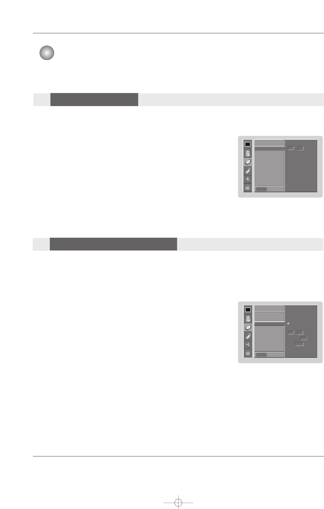
- If set to on and there is no input signal, the Monitor turns off automatically after 10 minutes.
1. Press the MENU button and then use DD / EEbutton to select the TIMER menu.
2. Press the GGbutton and then use DD / EEbutton to select Auto off.
3. Press the GGbutton and then use DD / EEbutton to select On or Off.
4. Press the ENTER button to save.
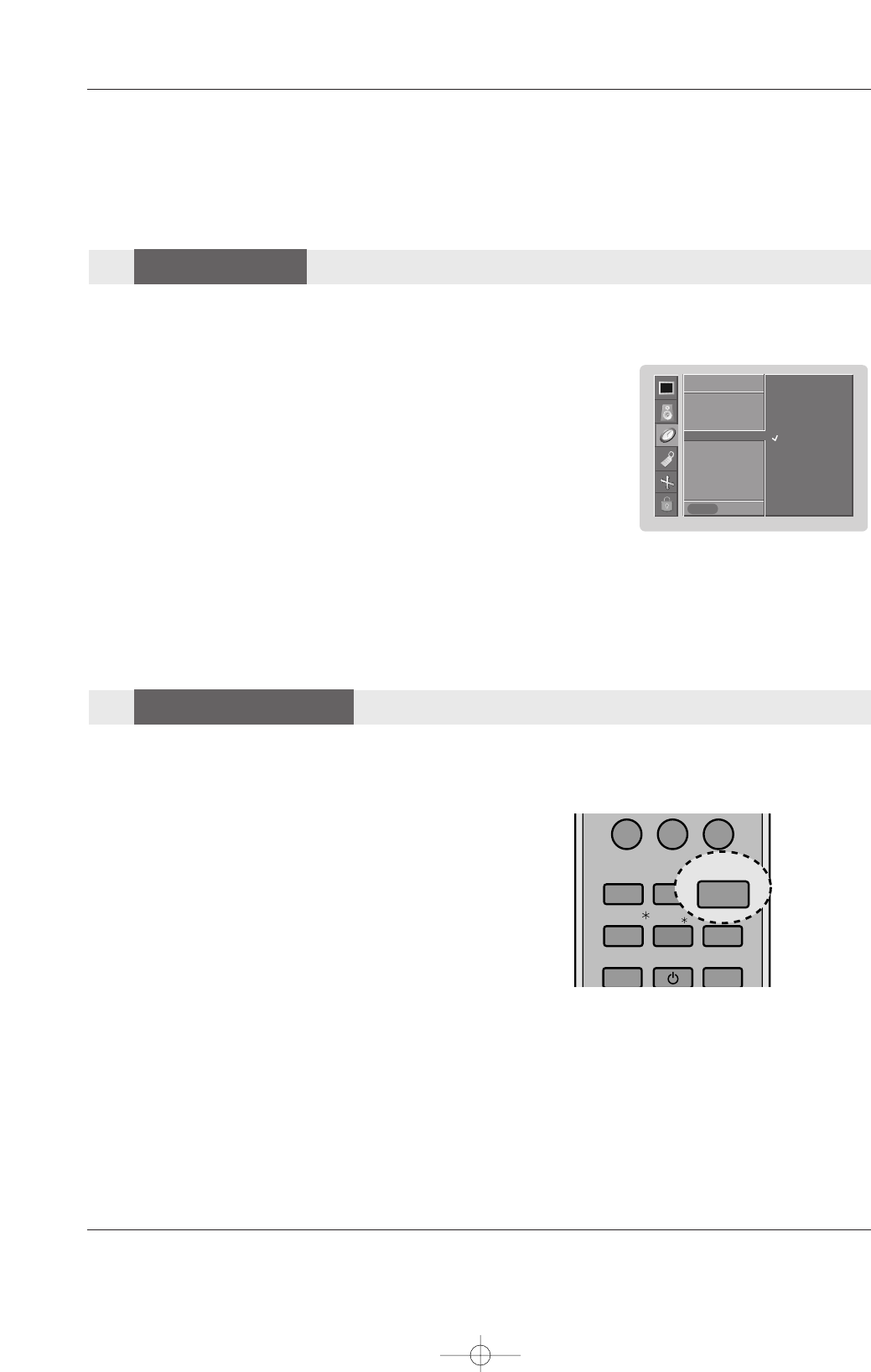
- The Sleep Timer turns the Monitor off at the preset time. Note that this setting is cleared when the Monitor is turned
off.
1. Press the SLEEP button repeatedly to select the number of min-
utes. First the Off option appears on the screen, followed by the
following sleep timer options: 10, 20, 30, 60, 90, 120, 180, and
240 minutes.
2. When the number of minutes you want is displayed on the
screen, press the OK button. The timer begins to count down
from the number of minutes selected.
3. To check the remaining minutes before the Monitor turns off, press
the SLEEP button once.
4. To cancel the Sleep Timer, press the SLEEP button repeatedly to
select Off.
TIMER
Prev.
Clock
Off timer
On timer
Auto off GG
TIMER
MENU
On
Off
Sleep T
Sleep Timer
imer
Auto Off
Auto Off
0
APC
DASP
SPLIT ZOOM
SLEEP
MEMORY/
ERASE/
REVIEW/
FCR/
A.PROG/
POWER
SLEEP
U514Aen 97/10/26 3:11 AM Page 23
24 Plasma Monitor
Special Features
- The Monitor can be set up so that it can only be used with the remote control.
- This feature can be used to prevent unauthorized viewing by locking out the front panel controls.
- This Monitor is programmed to remember which option it was last set to even if you turn the Monitor off.
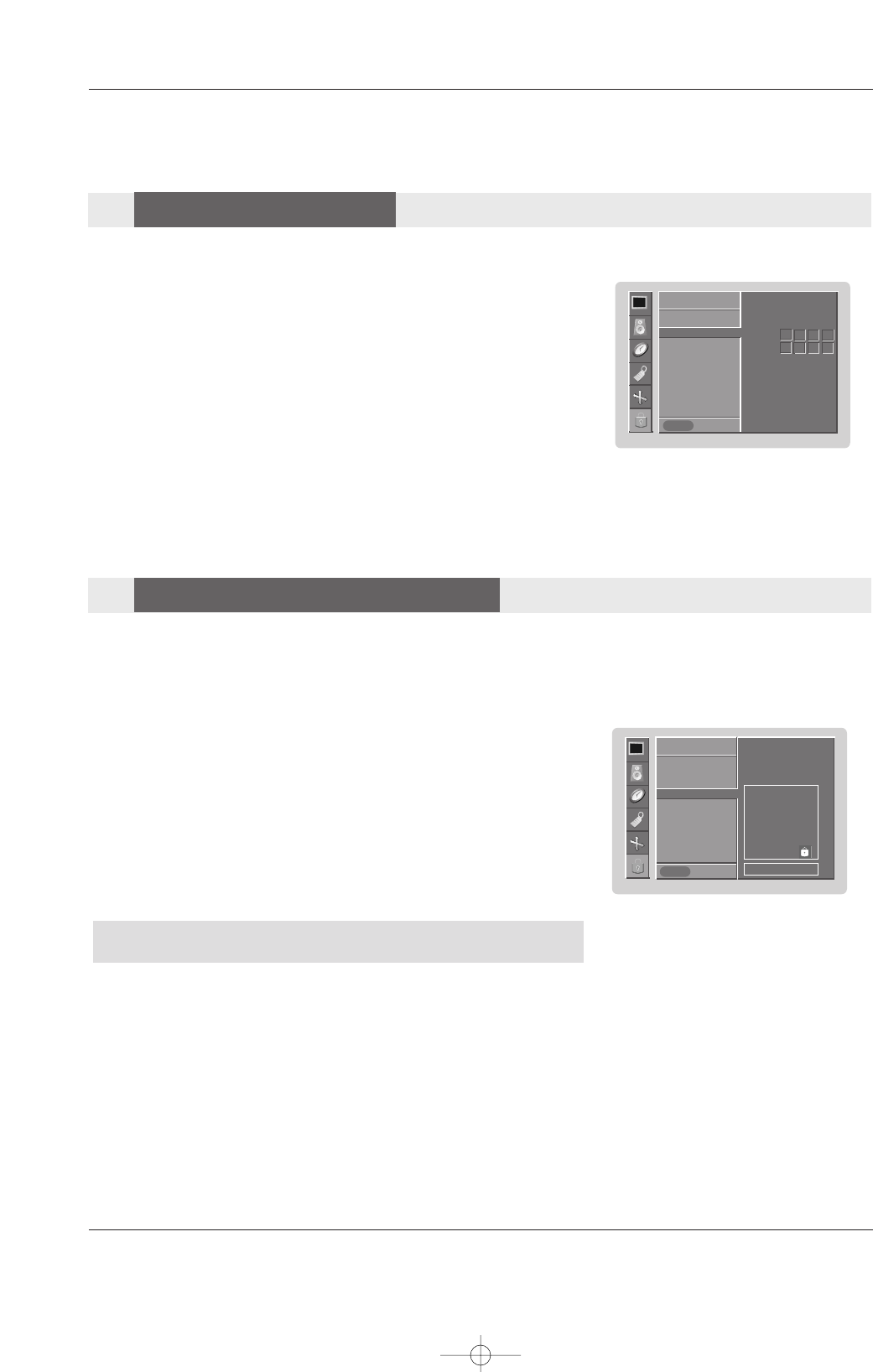
1. Press the MENU button and then use DD / EEbutton to select the SPECIAL menu.
2. Press the GGbutton and then use DD / EEbutton to select Key lock.
3. Press the GGbutton and then use DD / EEbutton to select On or Off.
4. Press the ENTER button to save.
• With the Key lock On, the display ‘ Key lock’appears on the screen if any
button on the front panel is pressed.
W
- A frozen still picture from a PC/video game displayed on the screen for prolonged periods will result in a ghost image remaining
even when you change the image. Avoid allowing a fixed image to remain on the Monitor's screen for a long period of time.
1. Press the MENU button and then use DD / EEbutton to select the SPECIAL menu.
2. Press the GGbutton and then use DD / EEbutton to select ISM Method.
3. Press the GGbutton and then use DD / EEbutton to select either Normal, White
wash, Orbiter or Inversion.
• Normal
If image sticking is never a problem, ISM is not necessary - set to Normal.
• White wash
White Wash removes permanent images from the screen. Note: An excessive
permanent image may be impossible to clear entirely with White Wash. To
return to normal viewing, press any button.
• Orbiter
Orbiter may help prevent ghost images. However, it is best not to allow any
fixed image to remain on the screen. To avoid a permanent image on the
screen, the image will move every 2 minutes: Right →Right → Downside →
Downside →Left →Left →Upside →Upside.
• Inversion
Inversion will automatically invert the Monitor panel color every 30 minutes.
4. Press the ENTER button to save.
SPECIAL
Prev.
Input
Language
Key lock GG
ISM Method
Low power
Set ID
Caption / Text
Demo
OSD Rotate
SPECIAL
MENU
On
Off
SPECIAL
Prev.
Input
Language
Key lock
ISM Method GG
Low power
Set ID
Caption / Text
Demo
OSD Rotate
SPECIAL
MENU
Normal
White wash
Orbiter
Inversion
Special Features
Key Lock
Key Lock
ISM
ISM (Image Sticking Minimization)
(Image Sticking Minimization) Method
Method
U514Aen 97/10/26 3:11 AM Page 24
Owner’s Manual 25
Special Features
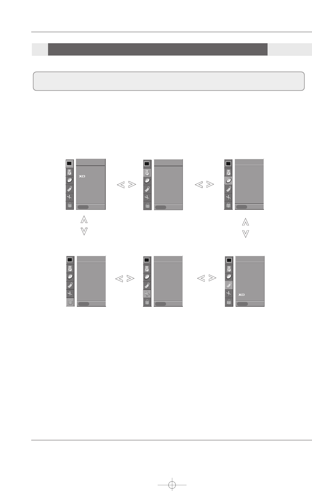
1. Press the MENU button and then use DD / EEbutton to select the SPECIAL menu.
2. Press the GGbutton and then use DD / EEbutton to select OSD Rotate.
3. Press the GGbutton and then use DD / EEbutton to select Normal or Rotate.
• Normal : If the set is installed horizontally.
• Rotate : If the set is installed vertically.
4. Press the ENTER button to save.
SPECIAL
Prev.
Input
Language
Key lock
ISM Method
Low power
Set ID
Caption / Text
Demo
OSD Rotate GG
SPECIAL
MENU
Normal
Rotate
- Low power reduces the plasma display power consumption.
1. Press the MENU button and then use DD / EEbutton to select the SPECIAL menu.
2. Press the GGbutton and then use DD / EEbutton to select Low power.
3. Press the GGbutton and then use DD / EEbutton to select On or Off.
• When you select On, the screen darkens.
4. Press the ENTER button to save.
1. Press the MENU button and then use DD / EEbutton to select the SPECIAL menu.
2. Press the GGbutton and then use DD / EEbutton to select Demo.
3. Press the GGbutton to begin
XD Demo
.
4. Press the MENU button to stop
XD Demo
.
- Use it to see the difference between XD Demo on and XD Demo off.
- XD demo is not available for RGB (PC) and HDMI (PC) sources.
SPECIAL
Prev.
Input
Language
Key lock
ISM Method
Low power GG
Set ID
Caption / Text
Demo
OSD Rotate
SPECIAL
MENU
On
Off
SPECIAL
Prev.
Input
Language
Key lock
ISM Method
Low power
Set ID
Caption / Text
Demo GG
OSD Rotate
SPECIAL
MENU
To start
Low Power
Low Power
XD Demo
XD Demo
OSD Rotate
OSD Rotate
U514Aen 97/10/26 3:11 AM Page 25
26 Plasma Monitor
Screen Adjustment
- If the image still isn’t clear after auto adjustment and especially if characters are still jittery, adjust the picture Phase
manually.
- To correct the screen size, adjust Clock.
- This function works in the following mode : RGB, COMPONENT, HDMI-DTV(480p, 720p,1080i).
-It’s not available to use Phase, Clock function in RGB, COMPONENT, HDMI-DTV (480p, 720p,1080i) mode.
1. Press the MENU button and then use DD / EEbutton to select the SCREEN menu.
2. Press the GGbutton and then use DD / EEbutton to select Manual config..
3. Press the GGbutton and then use DD / EEbutton to to select Phase,Clock,
H-Position or V-Position.
4. Use the FF / GGbutton to make appropriate adjustments.
• The Phase adjustment range is 0 ~ 63.
• The Clock adjustment range is -20 ~ +50.
5. Press the ENTER button to save.
- RGB (PC) mode only; This function doesn’t work for RGB (DTV) mode.
- Automatically adjusts picture position and minimizes image shaking.
- After adjustment, if the image is still not correct, your set is functioning properly but needs further adjustment.
- The Auto config. and Manual config. are not active in HDMI mode.
1. Press the MENU button and then use DD /EEbutton to select the SCREEN menu.
2. Press the GGbutton and then use DD /EEbutton to select Auto config..
3. Press the GGbutton to run Auto configure.
• When Auto config. has finished, OK will be shown on screen.
• If the position of the image is still not correct, try Auto adjustment again.
4. In RGB (PC) mode, if the image needs to be adjusted more after using Auto
config., you can make further adjustments with the Manual config. option.
- Caution: If a 4:3 fixed image is on the screen for a long time, it may remain visible.
- Set every aspect ratio for Video, Component 480i sources.
- Use 4:3 or 16:9 for other RGB(PC), HDMI(PC) sources.
- Horizon is not available for RGB (DTV), HDMI (DTV), and Component (DTV) sources.
1. Press the ARC button repeatedly to select the desired picture format. You can also adjust ARC in the SCREEN menu.
• 4:3
Choose 4:3 when you want to view a picture with an original 4:3 aspect ratio, with black bars appearing at both the left and right sides.
• 16:9
Choose 16:9 when you want to adjust the picture horizontally, in a linear proportion to fill the entire screen.
• Horizon
Choose Horizon when you want to adjust the picture in a non-linear proportion, that is, more enlarged at both sides, to create
a spectacular view.
• Zoom
-
Choose Zoom when you want to view the picture without any alteration. However, the top and bottom portions of the picture will be cropped.
SCREEN
Prev.
Auto config. GG
Manual config.
VGA Mode
ARC
Zoom +/-
Position
Cinema
NR
Reset
SCREEN
MENU
To set
SCREEN
Prev.
Auto config.
Manual config. GG
VGA Mode
ARC
Zoom +/-
Position
Cinema
NR
Reset
SCREEN
MENU
Phase 0
Clock 0
H-position 0
V-position 0
Screen Adjustment
Auto
Auto Adjustment
Adjustment
Setting Picture Format
Setting Picture Format
Manual Configure
Manual Configure
U514Aen 97/10/26 3:11 AM Page 26
Owner’s Manual 27
Screen Adjustment
- To see a normal picture, match the resolution of RGB VGA/XGA mode (640x480, 848x480, 852x480) with the
selection for VGA/XGA mode in the SCREEN menu.
1. Press the MENU button and then use DD /EEbutton to select the SCREEN menu.
2. Press the GGbutton and then use DD /EEbutton to select VGA Mode (or XGA
Mode).
3. Press the GGbutton and then use DD /EEbutton to select the desired VGA/XGA res-
olution.
4. Press the ENTER button to save.
SCREEN
Prev.
Auto config.
Manual config.
VGA Mode GG
ARC
Zoom +/-
Position
Cinema
NR
Reset
SCREEN
MENU
640x480
848x480
852x480
1. Press the MENU button and then use DD / EEbutton to select the SCREEN menu.
2. Press the GGbutton and then use DD / EEbutton to select Position.
3. Press the GGbutton and then use DD / EE / FF / GG button to adjust the position.
4. Press the ENTER button to save.
- You are available to this function after adjusting Zoom +/-.
- When enlarging or reducing the picture, the screen may be display unnatural picture.
1. Press the MENU button and then use DD / EEbutton to select the SCREEN
menu.
2. Press the GGbutton and then use DD / EEbutton to select Zoom+/-.
3. Press the GGbutton and then use DD / EE / FF / GG button to adjust the position.
4. Press the ENTER button to save.
SCREEN
Prev.
Auto config.
Manual config.
VGA Mode
ARC
Zoom +/-
Position GG
Cinema
NR
Reset
SCREEN
MENU
DD
FFGG
EE
SCREEN
Prev.
Auto config.
Manual config.
VGA Mode
ARC
Zoom +/- GG
Position
Cinema
NR
Reset
SCREEN
MENU
FFGG
Selecting VGA/XGA
Selecting VGA/XGA Mode
Mode (RGB mode only)
(RGB mode only)
Picture size Zoom
Picture size Zoom
Screen Position
Screen Position
105 %
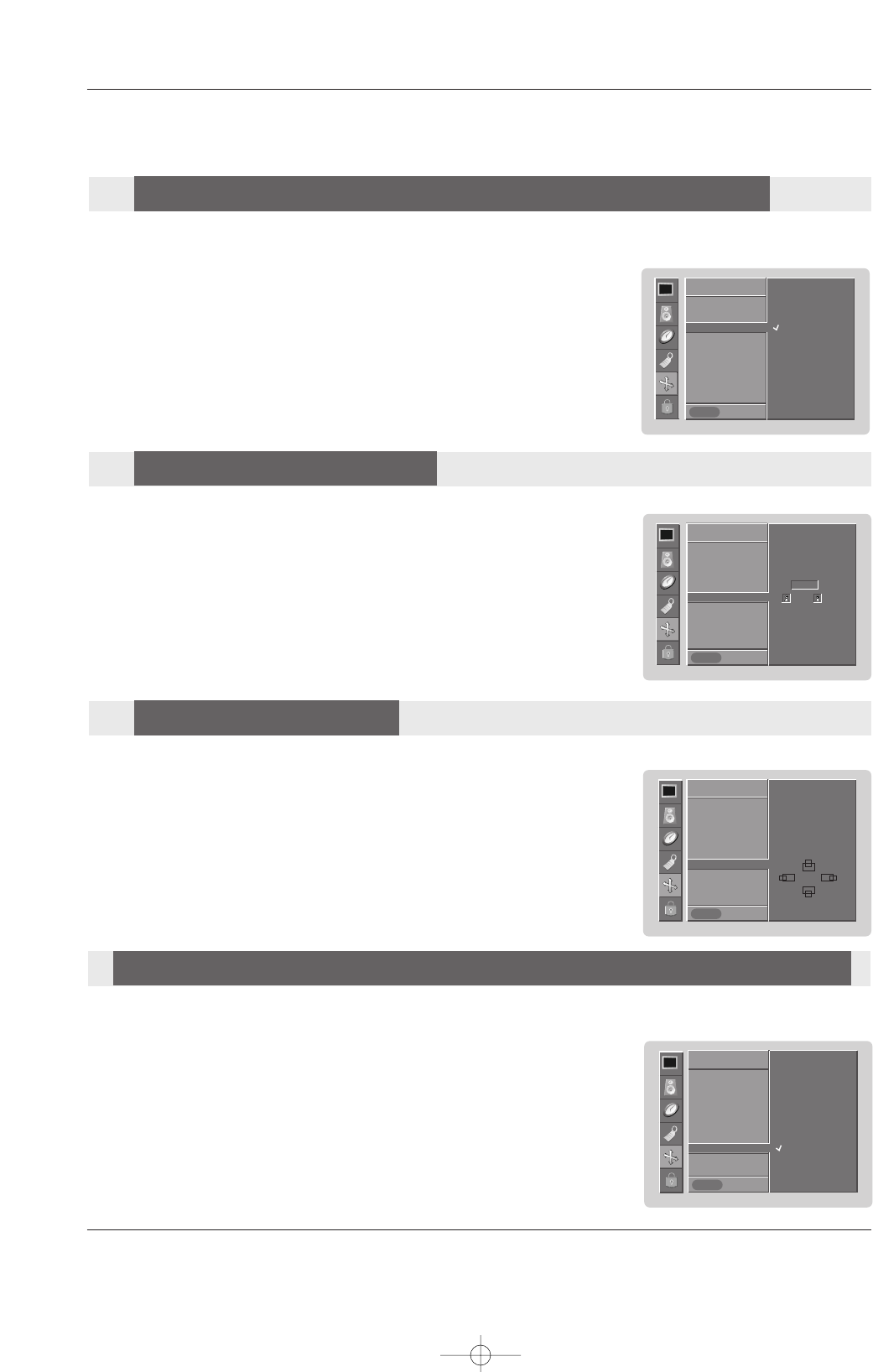
- Sets up the set for the best picture appearance for viewing movies.
- This function works in the following mode:
Video or COMPONENT (480i).
1. Press the MENU button and then use DD / EEbutton to select the SCREEN menu.
2. Press the GGbutton and then use DD / EEbutton to select Cinema..
3. Press the GGbutton and then use DD / EEbutton to select On or Off.
4. Press the ENTER button to save.
SCREEN
Prev.
Auto config.
Manual config.
VGA Mode
ARC
Zoom +/-
Position
Cinema GG
NR
Reset
SCREEN
MENU
On
Off
Cinema Mode Setup
Cinema Mode Setup (V
(Video and Component 480i mode only)
ideo and Component 480i mode only)
U514Aen 97/10/26 3:11 AM Page 27
28 Plasma Monitor
Screen Adjustment
- You can select 3D NR or MPEG NR to reduce the picture noise which may appear on the screen during watching the set.
1. Press the MENU button and then use DD / EEbutton to select the SCREEN menu.
2. Press the GGbutton and then use DD / EEbutton to select NR..
3. Press the GGbutton and then use DD / EEbutton to select 3D NR or MPEG NR.
4. Press the FF/ GGbutton to make appropriate adjustments.
5. Press the ENTER button to save.
SCREEN
Prev.
Auto config.
Manual config.
VGA Mode
ARC
Zoom +/-
Position
Cinema
NR GG
Reset
SCREEN
MENU
3D NR 0
MPGE NR 0
- Enlarges the picture in correct proportions.
- Split Zoom can be used for all input sources.
- In 2-Split Zoom mode, you can only move the image up or down.
- If an image is enlarged, a section can be viewed without using Split Zoom.
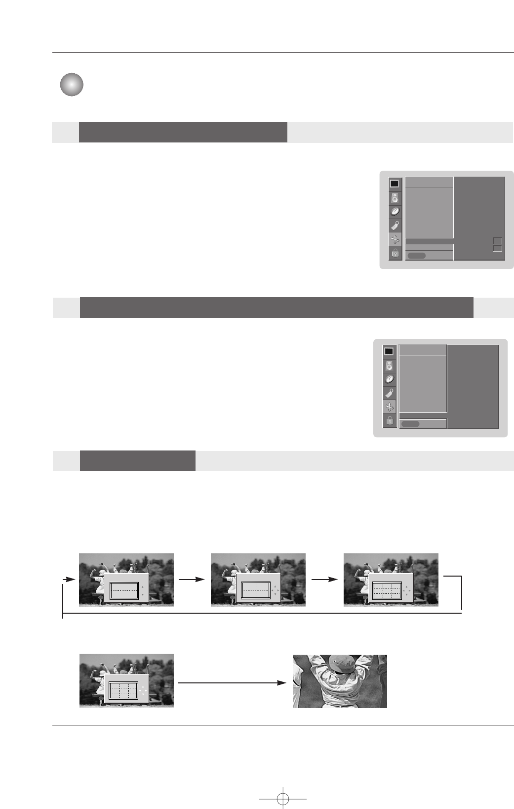
1. Press the SPLIT ZOOM button repeatedly to select either 2, 4, or 9 Split Zoom.
2. Press the number button corresponding to the section you wish to enlarge. You can move within the enlarged pic-
ture using the DD / EE / FF / GGbutton. To return to normal viewing, press the SPLIT ZOOM button again.
Example of choosing 5. Section 5 is enlarged to fill
the screen.
1
4
2-Split zoom
1
4
2
5
4-Split zoom
123
456
789
9-Split zoom
123
456
789
9-Split zoom
1. Press the MENU button and then use DD / EEbutton to select the SCREEN menu.
2. Press the GGbutton and then use DD / EEbutton to select Reset.
3. Press the GGbutton.
- Reset is unique to each function: Position, Zoom +/-.
- Use the Reset option to initialize the adjusted settings.
SCREEN
Prev.
Auto config.
Manual config.
VGA Mode
ARC
Zoom +/-
Position
Cinema
NR
Reset GG
SCREEN
MENU
To set
Screen Adjustment
Initializing (Reset to original factory value)
Initializing (Reset to original factory value)
Split Zoom
Split Zoom
NR (Noise Reduction)
NR (Noise Reduction)
U514Aen 97/10/26 3:11 AM Page 28
Owner’s Manual 29
Lock Adjustment
Parental Control can be used to block specific channels, ratings and other viewing sources.
The Parental Control Function (V-Chip) is used to block program viewing based on the ratings sent by the broadcasting station.
The default setting is to allow all programs to be viewed. Viewing can be blocked by choosing the type of the program and the cat-
egories. It is also possible to block all program viewing for a time period. To use this function, the following must be done :
1. Set ratings and categories to be blocked.
2. Specify a password
3. Enable the lock
V-Chip rating and categories
Rating guidelines are provided by broadcasting stations. Most television programs and television movies can be blocked by TV
Rating and/or Individual Categories. Movies that have been shown at the theaters or direct-to-video movies use the Movie Rating
System (MPAA) only.
Ratings for Television programs including made-for-TV movies :
• TV-G (General audience)
• TV-PG (Parental guidance suggested)
• TV-14 (Parents strongly cautioned)
• TV-MA (Mature audience only)
• TV-Y (All children)
• TV-Y7 (Children 7 years older)
Lock Adjustment
1. After inputting the password, use the DD /EEbutton to choose Lock System.
2. Press the GG button and then use the DD /EE to select On or Off.
• When you select , the Lock System is enable.
3. Press EXIT button to return to TV viewing or press MENU button to return to
the previous menu.
- Set up blocking schemes to block specific channels, ratings, and external viewing sources.
- A password is required to gain access to this menu.
Setting Up
Setting Up Y
Your Password
our Password
Enables or disables the blocking scheme you set up previously.
Lock System
Lock System
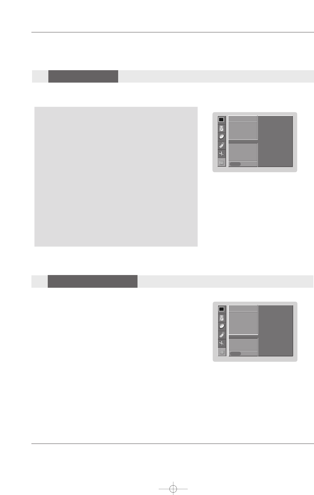
1. Press the MENU button and then use the DD / EEbutton to select the LOCK menu. Then, press the GGbutton.
• Enter the password as requested.
• The TV is set up with the initial password “0-0-0-0”.
LOCK
Prev.
Lock on/off GG
Set password
MPAA
Age block
Content block
Aux. block
LOCK
MENU
On
Off
Password :
** * *
U514Aen 97/10/26 3:11 AM Page 29
30 Plasma Monitor
Lock Adjustment
Set Password
Set Password
Change the password by inputting a new password twice.
1. After inputting the password, use the DD /EEbutton to choose Set password.
2. Press the GG button and then choose any 4 digits for your new password and
enter the them on the new.
As soon as the 4 digits are entered, re-enter the same 4 digits on the
Confirm.
Then your changed password has been memorized.
3. Press EXIT button to return to TV viewing or press MENU button to return to
the previous menu.
LOCK
Prev.
Lock on/off
Set password GG
MPAA
Age block
Content block
Aux. block
LOCK
MENU
New
Confirm *** *
*** *
MP
MPAA
AA (Movie Rating)
(Movie Rating)
Blocks movies according to the movie ratings limits specified, so children cannot view certain movies. You can set the ratings
limit by blocking out all the movies with the ratings above a specified level. Keep in mind that the movie ratings limit only
applies to movies shown on TV, not TV programs, such as soap operas.
1. After inputting the password, use the DD /EEbutton to choose MPAA.
2. Press the GG button and then use the DD /EE to select G&above,PG&above,
PG-13&above,R&above,NC-17&above,orX.
• Unblocked (Permits all programs)
• G&above (General audience)
• PG&above (Parental guidance suggested)
• PG-13&above (Parents strongly cautioned)
• R&above (Restricted)
• NC-17&above (No one 17 and under admitted)
• X (Adult only)
3. Press EXIT button to return to TV viewing or press MENU button to return to
the previous menu.
If you set PG-13&above : G&above and PG&above movies will be available ,
PG-13&above, R&above, NC-17&above and X will be blocked.
LOCK
Prev.
Lock on/off
Set password
MPAA GG
Age block
Content block
Aux. block
LOCK
MENU
G&above
PG&above
PG-13&above
R&above
NC-17&above
X
Unblocked
U514Aen 97/10/26 3:11 AM Page 30
Owner’s Manual 31
Lock Adjustment
Age block
Age block
LOCK
Prev.
Lock on/off
Set password
MPAA
Age block GG
Content block
Aux. block
LOCK
MENU
General
Children
General
• Based on the ratings, blocks certain monitor programs that you and your
family do not want to view.
• TV-G &above (General audience)
• TV-PG&above (Parental guidance suggested)
• TV-14&above (Parents strongly cautioned)
• TV-MA (Mature audience only)
Children
• Prevents children from watching certain children's monitor programs,
according to the ratings limit set. The children rating does not apply to
other Tmonitor programs. Unless you block certain monitor programs
intended for mature audiences in the monitor Rating - sub menu, your
children can view those programs.
• TV-Y&above (All children)
• TV-Y7 (Children 7 years older)
1. After inputting the password, use the DD /EEbutton to choose Age block.
2. Press the GG button and then use the DD /EE to select General or Children.
3. Press EXIT button to return to TV viewing or press MENU button to return to the
previous menu.
Content block
Content block
LOCK
Prev.
Lock on/off
Set password
MPAA
Age block
Content block GG
Aux. block
LOCK
MENU
Dialogue
Language
Sex scene
Violence
F.Violence
1. After inputting the password, use the DD /EEbutton to choose Content
block.
2. Press the GG button and then use the DD /EE to select Dialogue,
Language,Sex scene,Violence or F.Violence.
• Dialogue - sexual dialogue (applies to TV-PG&above, TV-14)
• Language - adult language (applies to TV-PG&above, TV-
14&above, TV-MA)
• Sex scene- sexual situations (applies to TV-PG&above, TV-
14&above, TV-MA)
• Violence (applies to TV-PG&above, TV-
14&above, TV-MA)
• F.Violence (applies to TV-Y7)
3. Press EXIT button to return to TV viewing or press MENU button to return
to the previous menu.
U514Aen 97/10/26 3:11 AM Page 31
32 Plasma Monitor
Lock Adjustment
Aux. block
Aux. block
LOCK
Prev.
Lock on/off
Set password
MPAA
Age block
Content block
Aux. block GG
LOCK
MENU
Enables you to select a source to block from the external source devices you have hooked up.
1. After inputting the password, use the DD /EEbutton to choose Aux. block.
2. Press the GG button and then use the DD /EE to select a source.
3. Press the GG button and then use the DD /EE to select Blocked or Unblocked
on the each source.
4. Press EXIT button to return to TV viewing or press MENU button to return to
the previous menu.
Note:
• If you ever forget your password, key in ‘7’, ‘7’, ‘7’, ‘7’ on the remote control.
RGB
HDMI
Component 1
Component 2
Video
U514Aen 97/10/26 3:11 AM Page 32
Owner’s Manual 33
External Control Device Setup
RS-232C INPUT
(CONTROL/SERVICE)
AUDIO
AUDIO
LR
REMOTE
CONTROL
AUDIO INPUT
RGB INPUT
VARIABLE
ARIABLE
AUDIO OUT
AUDIO OUT
HDMI/
DVI(VIDEO)
RGB OUTPUT
AUDIO
VIDEO
RL
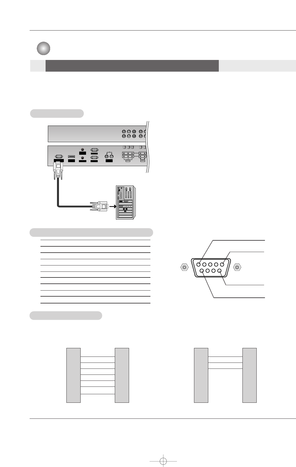
No. Pin name
1 No connection
2 RXD (Receive data)
3 TXD (Transmit data)
4 DTR (DTE side ready)
5 GND
6 DSR (DCE side ready)
7 RTS (Ready to send)
8 CTS (Clear to send)
9 No Connection
1
5
6
9
2
3
5
4
6
7
8
RXD
TXD
GND
DTR
DSR
RTS
CTS
TXD
RXD
GND
DSR
DTR
CTS
RTS
PC
7-Wire Configurations
(Standard RS-232C cable)
D-Sub 9
3
2
5
6
4
8
7
PDP
D-Sub 9
2
3
5
4
6
7
8
RXD
TXD
GND
DTR
DSR
RTS
CTS
TXD
RXD
GND
DTR
DSR
RTS
CTS
PC
3-Wire Configurations
(Not standard)
D-Sub 9
3
2
5
4
6
7
8
PDP
D-Sub 9
- Connect the RS-232C input jack to an external control device (such as a computer or an A/V control system)
and control the Monitor’s functions externally.
- Connect the serial port of the control device to the RS-232C jack on the Monitor back panel.
- RS-232C connection cables are not supplied with the Monitor.
- RS-232C connection cables are used for service.
T
Type of Connector; D-Sub 9-Pin Male
ype of Connector; D-Sub 9-Pin Male
RS-232C Configurations
RS-232C Configurations
RS-232C Setup
RS-232C Setup
PC
Appendix
Appendix
External Control Device Setup
External Control Device Setup
U514Aen 97/10/26 3:11 AM Page 33
34 Plasma Monitor
External Control Device Setup
Set ID
Set ID
- Use this function to specify a Monitor ID number.
- Refer to ‘Real Data Mapping 1’. See page 36.
1. Press the MENU button and then use DD /EEbutton to select the SPECIAL menu.
2. Press the GGbutton and then use DD /EEbutton to select Set ID.
3. Press the GGbutton and then use F / Gbutton to adjust Set ID to choose the
desired Monitor ID number. The adjustment range of Set ID is 1 ~ 99.
4. Press the ENTER button to save.
Transmission
* [Command 1] : First command to control PDP set.
(j, k, m or x)
* [Command 2] : Second command to control PDP set.
* [Set ID] : You can adjust the set ID to choose
desired monitor ID number in special
menu.
Adjustment range is 1 ~ 99.
When selecting Set ID ‘0’, every
connected PDP set is controlled.
Set ID is indicated as decimal (1~99) on
menu and as Hexa decimal (0x0~0x63)
on transmission/receiving protocol.
* [DATA] : To transmit command data.
Transmit ‘FF’data to read status of
command.
* [Cr] : Carriage Return
ASCII code ‘0x0D’
* [ ] : ASCII code ‘space (0x20)’
[Command1][Command2][ ][Set ID][ ][Data][Cr]
OK Acknowledgement
* The Monitor transmits ACK (acknowledgement) based on
this format when receiving normal data. At this time, if the
data is data read mode, it indicates present status data. If
the data is data write mode, it returns the data of the PC
computer.
[Command2][ ][Set ID][ ][OK][Data][x]
Error Acknowledgement
* The Monitor transmits ACK (acknowledgement) based on
this format when receiving abnormal data from
non-viable functions or communication errors.
[Command2][ ][Set ID][ ][NG][Data][x]
Transmission / Receiving Protocol
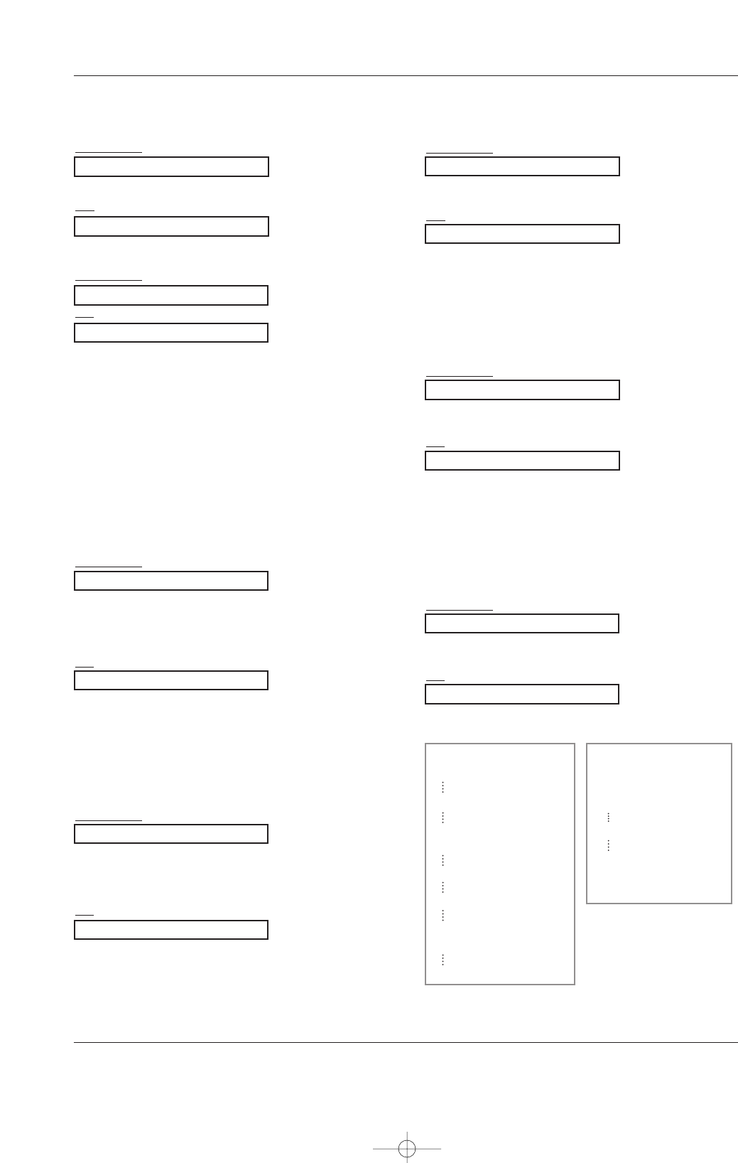
Command Reference List
*When setting the 22 ~ 27, a menu doesn’t display on screen.
Data 1: Illegal Code
2: not support function
3: Wait more time
01. Power k a 0 ~ 1
02. Input Select k b 0 ~ 6
03. Aspect Ratio k c Refer to p. 37
04. Screen Mute k d 0 ~ 1
05. Volume Mute k e 0 ~ 1
06. Volume Control k f 0 ~ 64
07. Contrast k g 0 ~ 64
08. Brightness k h 0 ~ 64
09. Color k i 0 ~ 64
10. Tint (option) k j 0 ~ 64
11. Sharpness k k 0 ~ 64
12. OSD Select k l 0 ~ 1
13.
Remote control lock mode
k m 0 ~ 1
14. Split Zoom k p 0 ~ 99
15. Treble k r 0 ~ 64
16. Bass k s 0 ~ 64
17. Balance k t 0 ~ 64
18.
Color Temperature (ACC)
k u 0 ~ 3
19. Red Adjustment k v 0 ~ 50
20. Green Adjustment k w 0 ~ 50
21. Blue Adjustment k $ 0 ~ 50
22. Abnormal Status k z 0 ~ a
23. ISM Method j p 0 ~ 3
24. Low Power j q 0 ~ 1
25. Orbiter Time Setting j r 1 ~ FE
26. Orbiter Pixel Setting j s 1 ~ 3
27. Auto Configure j u 1
28. Key m c Key Code
COMMAND 1 COMMAND 2 DATA
(Hexadecimal)
• Baud rate : 9600 bps (UART)
• Data length : 8 bits
• Parity : None
* Use a crossed (reverse) cable.
• Stop bit : 1 bit
• Communication code : ASCII code
Communication Parameters
SPECIAL
Prev.
Input
Language
Key lock
ISM Method GG
Low power
Set ID
Caption / Text
Demo
OSD Rotate
SPECIAL
MENU
1
U514Aen 97/10/26 3:11 AM Page 34
Owner’s Manual 35
External Control Device Setup
05. Volume Mute (Command 2 : e)
GTo control volume mute on/off.
You can also adjust mute using the MUTE button on
remote control.
Transmission
Data 0 : Volume mute off (Volume on)
1 : Volume mute on (Volume off)
[k][e][ ][Set ID][ ][Data][Cr]
Ack
[e][ ][Set ID][ ][OK][Data][x]
03. Aspect Ratio (Command 2 : c) (Main Picture Size)
GTo adjust the screen format. (Main picture format)
You can also adjust the screen format using the ARC
(Aspect Ratio Control) button on remote control or in the
SCREEN menu.
Transmission
Data 1 : Normal screen (4:3)
2 : Wide screen (16:9)
3 : Horizon
4 : Zoom
[k][c][ ][Set ID][ ][Data][Cr]
Ack
* Using the PC input, you select either 16:9 or 4:3 screen
aspect ratio.
[c][ ][Set ID][ ][OK][Data][x]
04. Screen Mute (Command 2 : d)
GTo select screen mute on/off.
Transmission
Data 0 : Screen mute off (Picture on)
1 : Screen mute on (Picture off)
[k][d][ ][Set ID][ ][Data][Cr]
Ack
[d][ ][Set ID][ ][OK][Data][x]
06. Volume Control (Command 2 : f)
GTo adjust volume.
You can also adjust volume with the volume buttons
on remote control.
Transmission
Data Min : 0 ~ Max : 64
* Refer to ‘Real data mapping 1’.
[k][f][ ][Set ID][ ][Data][Cr]
Ack
[f][ ][Set ID][ ][OK][Data][x]
02. Input Select (Command 2 : b)
GTo select input source for the monitor.
You can also select an input source using the INPUT but-
ton on the Monitor's remote control.
Transmission
Data 0 : RGB
1 : HDMI
2 : Video
4 : Component1
5 : Component2
[k][b][ ][Set ID][ ][Data][Cr]
Ack
[b][ ][Set ID][ ][OK][Data][x]
01. Power (Command2:a)
GTo control Power On/Off of the monitor.
Transmission
Data 0 : Power Off 1 : Power On
[k][a][ ][Set ID][ ][Data][Cr]
Ack
[a][ ][Set ID][ ][OK][Data][x]
GTo show Power On/Off.
Transmission
[k][a][ ][Set ID][ ][FF][Cr]
Ack
* In like manner, if other functions transmit ‘0xFF’data
based on this format, Acknowledgement data feed back
presents status about each function.
[a][ ][Set ID][ ][OK][Data][x]
* Real data mapping 1
0 : Step 0
A : Step 10 (Set ID 10)
F : Step 15 (Set ID 15)
10 : Step 16 (Set ID 16)
64 : Step 100
6E : Step 110
73 : Step 115
74 : Step 116
C7 : Step 199
* Real data mapping 2
0 : -40
1 : -39
2 : -38
28 : 0
4E : +38
4F : +39
50 : +40
U514Aen 97/10/26 3:11 AM Page 35
36 Plasma Monitor
External Control Device Setup
07. Contrast (Command 2 : g)
GTo adjust screen contrast.
You can also adjust contrast in the PICTURE menu.
Transmission
Data Min : 0 ~ Max : 64
* Refer to ‘Real data mapping 1’. See page 36.
[k][g][ ][Set ID][ ][Data][Cr]
Ack
[g][ ][Set ID][ ][OK][Data][x]
08. Brightness (Command 2 : h)
GTo adjust screen brightness.
You can also adjust brightness in the PICTURE menu.
Transmission
Data Min : 0 ~ Max : 64
* Refer to ‘Real data mapping 1’. See page 36.
[k][h][ ][Set ID][ ][Data][Cr]
Ack
[h][ ][Set ID][ ][OK][Data][x]
13. Remote control lock mode (Command 2 : m)
GTo lock the front panel controls on the monitor and remote
control.
Transmission
[k][m][ ][Set ID][ ][Data][Cr]
Ack
Data 0 : Lock off 1 : Lock on
* If you’re not using the remote control, use this mode.
When main power is on/off, external control lock is
released.
[m][ ][Set ID][ ][OK][Data][x]
12. OSD Select (Command 2 : l)
GTo select OSD (On Screen Display) on/off when con-
trolling remotely.
Transmission
[k][l][ ][Set ID][ ][Data][Cr]
Ack
Data 0 : OSD off 1 : OSD on
[l][ ][Set ID][ ][OK][Data][x]
09. Color (Command 2 : i)
GTo adjust the screen color.
You can also adjust color in the PICTURE menu.
Transmission
Data Min : 0 ~ Max : 64
* Refer to ‘Real data mapping 1’. See page 36.
[k][i][ ][Set ID][ ][Data][Cr]
Ack
[i][ ][Set ID][ ][OK][Data][x]
10. Tint (Command 2 : j) (option)
GTo adjust the screen tint.
You can also adjust tint in the PICTURE menu.
Transmission
Data Red : 0 ~ Green : 64
* Refer to ‘Real data mapping 1’. See page 36.
[k][j][ ][Set ID][ ][Data][Cr]
Ack
[j][ ][Set ID][ ][OK][Data][x]
GTo adjust the screen sharpness.
You can also adjust sharpness in the PICTURE menu.
Transmission
11. Sharpness (Command 2 : k)
Data Min : 0 ~ Max : 64
* Refer to ‘Real data mapping 1’. See page 36.
[k][k][ ][Set ID][ ][Data][Cr]
Ack
[k][ ][Set ID][ ][OK][Data][x]
14. Split Zoom (Command2:p)
GTo operate split zoom function and select the split
zoom section number.
Transmission
Data Min: 0 ~ Max:99
•Refer to ‘Real data mapping 2’.
[k][p][ ][Set ID][ ][Data][Cr]
Acknowledgement
[p][ ][Set ID][ ][OK][Data][x]
* Real data mapping 2
0 : Reset split zoom
21: Selection 1 of 2 split zoom
24: Selection 4 of 2 split zoom
41: Selection 1 of 4 split zoom
42: Selection 2 of 4 split zoom
44: Selection 4 of 4 split zoom
45: Selection 5 of 4 split zoom
91: Selection 1 of 9 split zoom
99: Selection 9 of 9 split zoom
U514Aen 97/10/26 3:11 AM Page 36
Owner’s Manual 37
External Control Device Setup
20. Green Adjustment (Command 2 : w)
GTo adjust green in color temperature.
Transmission
Data Min : 0 ~ Max : 50
* Refer to ‘Real data mapping 2’. See page 36.
[k][w][ ][Set ID][ ][Data][Cr]
Ack
[w][ ][Set ID][ ][OK][Data][x]
21. Blue Adjustment (Command 2 : $)
GTo adjust blue in color temperature.
Transmission
Data Min : 0 ~ Max : 50
* Refer to ‘Real data mapping 2’. See page 36.
[k][$][ ][Set ID][ ][Data][Cr]
Ack
[$][ ][Set ID][ ][OK][Data][x]
19. Red Adjustment (Command 2 : v)
GTo adjust red in color temperature.
Transmission
Data Min : 0 ~ Max : 50
* Refer to ‘Real data mapping 2’. See page 36.
[k][v][ ][Set ID][ ][Data][Cr]
Ack
[v][ ][Set ID][ ][OK][Data][x]
18. Color Temperature (Command 2 : u)
GTo adjust color temperature.
You can also adjust ACC in the PICTURE menu.
Transmission
Data 0: Cool 1: Normal 2: Warm 3: User
[k][u][ ][Set ID][ ][Data][Cr]
Ack
[u][ ][Set ID][ ][OK][Data][x]
16. Bass (Command 2 : s)
GTo adjust bass.
You can also adjust bass in the SOUND menu.
Transmission
Data Min : 0 ~ Max : 64
* Refer to ‘Real data mapping 1’. See page 36.
[k][s][ ][Set ID][ ][Data][Cr]
Ack
[s][ ][Set ID][ ][OK][Data][x]
15. Treble (Command 2 :r)
GTo adjust treble.
You can also adjust treble in the SOUND menu.
Transmission
Data Min : 0 ~ Max : 64
* Refer to ‘Real data mapping 1’. See page 36.
[k][r][ ][Set ID][ ][Data][Cr]
Ack
[r][ ][Set ID][ ][OK][Data][x]
17. Balance (Command 2 : t)
GTo adjust balance.
You can also adjust balance in the SOUND menu.
Transmission
Data Min : 0 ~ Max : 64
* Refer to ‘Real data mapping 1’. See page 36.
[k][t][ ][Set ID][ ][Data][Cr]
Ack
[t][ ][Set ID][ ][OK][Data][x]
U514Aen 97/10/26 3:11 AM Page 37
38 Plasma Monitor
External Control Device Setup
22. Abnormal State (Command 2 : z)
GTo recognize an abnormal state.
Transmission
Data FF : Read
Data 0: Normal (Power on and signal exist)
1: No signal (Power on)
2: Turn the monitor off by remote control
3: Turn the monitor off by sleep time function
4: Turn the monitor off by RS-232C function
5: 5V down
6: AC down
7: Turn the monitor off by Fan Alarm function (option)
8: Turn the monitor off by Off time function
9: Turn the monitor off by Auto sleep function
a: Turn the monitor off by AV board detect
* This function is “read only”.
[k][z][ ][Set ID][ ][FF][ ][Cr]
Ack
[z][ ][Set ID][ ][OK][Data][x]
23. ISM Method
(Command 1 : j, Command 2 : p)
GTo control the ISM method. You can also adjust ISM
Method in SPECIAL menu.
Transmission
Data 0 : Normal Mode
1 : White Wash
2 : Orbiter
3 : Inversion
[j][p][ ][Set ID][ ][Data][Cr]
Ack
[p][ ][Set ID][ ][OK][Data][x]
24. Low Power
(Command 1 : j, Command 2 : q)
GTo reduce the power consumption of the monitor. You
can also adjust Low Power in SPECIAL menu.
Transmission
Data 0 : Off
1 : On
[j][q][ ][Set ID][ ][Data][ ][Cr]
Ack
[q][ ][Set ID][ ][OK][Data][x]
25. Orbiter Time Setting
(Command 1 : j, Command 2 : r)
GTo adjust orbiter operation time term.
Transmission
Data Min: 1 ~ Max: FE
* Refer to ‘Real data mapping 1’. See page 36.
[j][r][ ][Set ID][ ][Data][ ][Cr]
Ack
[r][ ][Set ID][ ][OK][Data][x]
26. Orbiter Pixel Setting
(Command 1 : j, Command 2 : s)
GTo adjust pixel number in orbiter function.
Transmission
Data Min: 1 ~ Max: 3
* Refer to ‘Real data mapping 1’. See page 36.
[j][s][ ][Set ID][ ][Data][Cr]
Ack
[s][ ][Set ID][ ][OK][Data][x]
27. Auto Configure
(Command 1 : j, Command 2 : u)
GTo adjust picture position and minimize image shaking
automatically. It works only in RGB (PC) mode.
Transmission
Data 1: To set
[j][u][ ][Set ID][ ][Data][Cr]
Ack
[u][ ][Set ID][ ][OK][Data][x]
28. Key
(Command 1 : m, Command 2 : c)
GTo send IR remote key code.
Transmission
Data Key code - Refer to page 37.
[m][c][ ][Set ID][ ][Data][Cr]
Ack
[c][ ][Set ID][ ][OK][Data][x]
U514Aen 97/10/26 3:11 AM Page 38
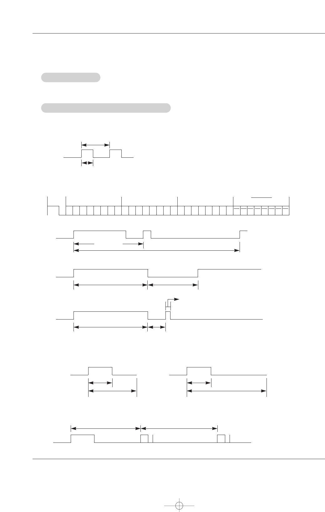
Owner’s Manual 39
IR Codes
G Output waveform
Single pulse, modulated with 37.917KHz signal at 455KHz
G Configuration of frame
G Repeat code
G Lead code
• 1st frame
Low
custom code
Lead
code
High
custom code Data code Data code
TC
Tf
T1
C0
Carrier frequency
FCAR = 1/TC= fOSC/12
Duty ratio = T1/TC= 1/3
• Repeat frame
C1 C2 C3 C4 C5 C6 C7 C0 C1 C2 C3 C4 C5 C6 C7 D0 D1 D2 D3 D4 D5 D6 D7 D0 D1 D2 D3 D4 D5 D6 D7
Repeat code
9 ms 4.5 ms
0.55 ms
9 ms
2.25 ms
G Bit description
G Frame interval : Tf
The waveform is transmitted as long as a key is depressed.
• Bit “0”
Tf Tf
Tf=108ms @455KHz
0.56 ms 0.56 ms
1.12 ms
• Bit “1”
2.24 ms
How to Connect
How to Connect
Remote Control IR Code
Remote Control IR Code
IR Codes
IR Codes
G Connect your wired remote control to the Remote Control port on the Monitor.
U514Aen 97/10/26 3:11 AM Page 39
40 Plasma Monitor
IR Codes
Code (Hexa) Function Note
00
01
02
03
08
C4
C5
09
5B
10
11
12
13
14
15
16
17
18
19
98
0B
5A
BF
D4
C6
D5
0E
43
44
4D
52
5D
5C
79
76
77
AF
39
99
R/C Button
R/C Button
R/C Button
R/C Button
R/C Button (Power On/Off)
Discrete IR Code (Only Power On)
Discrete IR Code (Only Power Off)
R/C Button
R/C Button
R/C Button
R/C Button
R/C Button
R/C Button
R/C Button
R/C Button
R/C Button
R/C Button
R/C Button
R/C Button
R/C Button
R/C Button
Discrete IR Code (Input VIDEO Selection)
Discrete IR Code (Input COMPONENT1 Selection)
Discrete IR Code (Input COMPONENT2 Selection)
Discrete IR Code (Input HDMI Selection)
Discrete IR Code (Input RGB Selection)
R/C Button
R/C Button
R/C Button
R/C Button
R/C Button
R/C Button
R/C Button
R/C Button
Discrete IR Code (Only 4:3 mode)
Discrete IR Code (Only 16:9 mode)
Discrete IR Code (Only Zoom mode)
Discrete IR Code
Discrete IR Code
D
E
VOL (G)
VOL (F)
POWER
POWER ON
POWER OFF
MUTE
EXIT
Number Key 0
Number Key 1
Number Key 2
Number Key 3
Number Key 4
Number Key 5
Number Key 6
Number Key 7
Number Key 8
Number Key 9
MULTIMEDIA
INPUT
VIDEO
COMPONENT1
COMPONENT2
HDMI
RGB
SLEEP
MENU
ENTER
APC
DASP
ZOOM -
ZOOM +
ARC
ARC (4:3)
ARC (16:9)
ARC (Zoom)
CAPTION
AUTO CONFIG
U514Aen 97/10/26 3:11 AM Page 40
Owner’s Manual 41
Troubleshooting Checklist
No output from one of
the speakers •Adjust Balance in the Sound menu. (Refer to p.23)
Unusual sound from
inside the Monitor
•A change in ambient humidity or temperature may result in an unusual noise
when the plasma display is turned on or off and does not indicate a fault with
the Monitor.
No picture &
No sound
•Check whether the Monitor is turned on.
•Is the power cord inserted into wall power outlet?
•Test the wall power outlet, plug another product’s power cord into the outlet
where the Monitor’s power cord was plugged in.
No or poor color
or poor picture
•Select Color in the Picture menu and press the VOLUME (G) button.
(Refer to p.21)
•Keep a sufficient distance between the Monitor and the VCR.
•Activate any function to restore the brightness of the picture.
(If still picture is on the screen for more than 5 minutes, the screen gets dark.)
The remote control
doesn’t work
•Check to see if there is any object between the Monitor and the remote con-
trol causing obstruction.
•Are batteries installed with correct polarity (+ to +, - to -)?
(Refer to p.8)
•Correct remote operating mode set: Monitor, VCR etc.?
•Install new batteries. (Refer to p.8)
Picture OK &
No sound
•Press the VOLUME (G) button.
•Sound muted? Press MUTE button.
Picture appears slowly
after switching on
•This is normal, the image is muted during the Monitor startup process.
Please contact your service center, if the picture has not appeared after five
minutes.
Horizontal/vertical bars
or picture shaking •Check for local interference such as an electrical appliance or power tool.
T
Troubleshooting Checklist
roubleshooting Checklist
U514Aen 97/10/26 3:11 AM Page 41
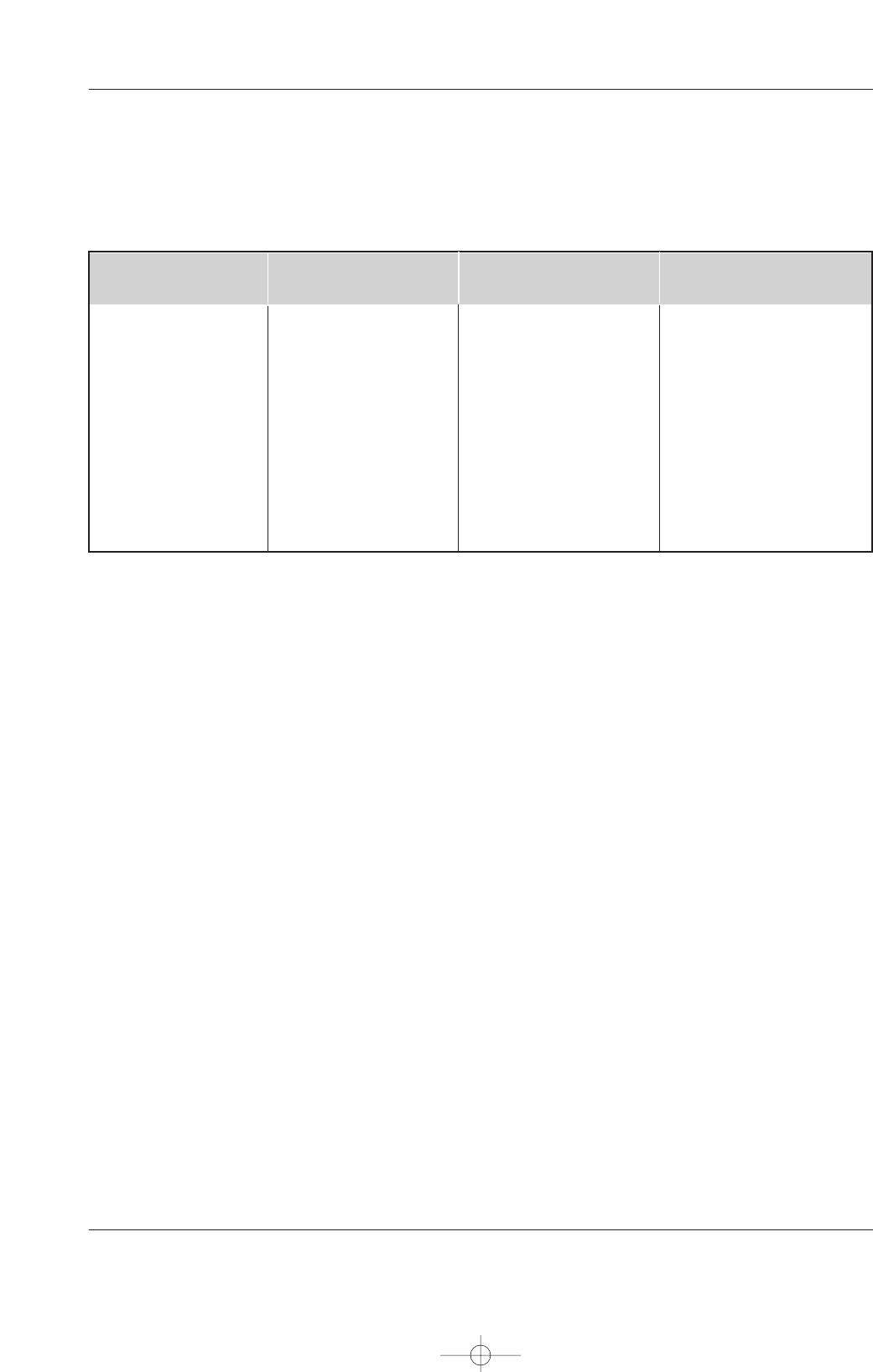
42 Plasma Monitor
Product Specifications
Product Specifications
Product Specifications
•The specifications shown above may be changed without notice for quality improvement.
MODELS
41.4 / 1050
24.8 / 630
3.6 / 91.5
64 / 29
852 x 480 (Dot)
AC100-240V, 50/60Hz
32 ~ 104°F (0 ~ 40°C)
Less than 80%
Width (inches / mm)
Height (inches / mm)
Depth (inches / mm)
Weight (pounds / kg)
Resolution
Power requirement
Operating Temperature Range
Operating Humidity Range
42PM1M-UC 42PM3MV-UC 50PM3MV-UC
41.4 / 1050
24.8 / 630
3.6 / 91.5
64 / 29
852 x 480 (Dot)
AC100-240V, 50/60Hz
32 ~ 104°F (0 ~ 40°C)
Less than 80%
Width (inches / mm)
Height (inches / mm)
Depth (inches / mm)
Weight (pounds / kg)
Resolution
AC100-240V, 50/60Hz
32 ~ 104°F (0 ~ 40°C)
Less than 80%
U514Aen 97/10/26 3:11 AM Page 42
Your LG Plasma TV will be repaired or replaced in accordance with the terms of this warranty, at LGE’s option, if it
proves to be defective in material or workmanship under normal use, during the warranty period (“Warranty Period”)
listed below, effective from the date (“Date of Purchase”) of original consumer purchase of the product. This war-
ranty is good only to the original purchaser of the product and effective only when used in the United States, includ-
ing Alaska, Hawaii, and U.S. Territories.
LG ELECTRONICS, INC.
PLASMA TV — U.S. LIMITED WARRANTY
CONCERNING PIXEL FUNCTIONALITY: Your Plasma TV contains about one million individual pixels. Plasma TV
typically contain a small number of pixels that do not function normally. Your display has been inspected and is in
compliance with manufacturer’s specifications, indicating that any pixel defects do not effect the operation or use
of your display.
THIS WARRANTY IS IN LIEU OF ANY OTHER WARRANTY, EXPRESS OR IMPLIED, INCLUDING WITHOUT
LIMITATION, ANY WARRANTY OF MERCHANTABILITY OR FITNESS FOR A PARTICULAR PURPOSE. TO THE
EXTENT ANY IMPLIED WARRANTY IS REQUIRED BY LAW, IT IS LIMITED IN DURATION TO THE EXPRESS
WARRANTY PERIOD ABOVE. NEITHER THE MANUFACTURER NOR ITS U.S. DISTRIBUTOR SHALL BE
LIABLE FOR ANY INCIDENTAL, CONSEQUENTIAL, INDIRECT, SPECIAL, OR PUNITIVE DAMAGES OF ANY
NATURE, INCLUDING WITHOUT LIMITATION, LOST PROFITS, LOST OR CORRUPTED PROGRAMMING OR
DATA, OR ANY OTHER DAMAGE WHETHER BASED IN CONTRACT, TORT, OR OTHERWISE. Some states do
not allow the exclusion or limitation of incidental or consequential damages or limitations on how long an implied
warranty lasts, so the above exclusion or limitation may not apply to you. This warranty gives you specific legal
rights and you may also have other rights that vary from state to state.
WARRANTY PERIOD:
LABOR and PARTS: 2 YEARS from the Date of Purchase.
Your unit will be repaired or replaced with a new, substitute
model or factory reconditioned unit, at LGE’s option. If
repaired, parts used in the repair may be new or remanufac-
tured.
Replacement Units and Repair Parts are warranted for the
remaining portion of the original unit’s warranty period.
EFFECTIVE DATE OF WARRANTY: Your warranty period
begins on the date of sale to the original consumer/end user.
KEEP THE DEALER’S DATED BILL OF SALE OR PROOF OF
DELIVERY as evidence of the purchase date. You will be
required to submit a legible copy of your bill of sale or proof
of delivery when requesting warranty service.
HOW SERVICE IS HANDLED:
In-Home Service: Please retain dealer’s
dated bill of sale or delivery ticket as evidence
of the Date of Purchase for proof of warranty,
and submit a copy of the bill of sale to the ser-
vice person at the time warranty service is pro-
vided.
Please call 1-800-243-0000 to locate your
nearest LGE Authorized Service Center.
Visit our website at:
http://www.lgservice.com
IMPORTANT: Please fill out and mail in your Product Registration Card or go to www.lgservice.com to register your
product online. This information will allow us to reach you promptly should we discover a safety or reliability prob-
lem that could affect you.
U514Aen 97/10/26 3:11 AM Page 43

P/N : 38289U0514A
sTO CONTACT THE LGE CUSTOMER SERVICE CENTER BY MAIL:
LGE Customer Interactive Center
P.O. Box 240007
201 James Record Road
Huntsville, Alabama 35824
http://www.lgservice.com
FOR SERVICE:
Before you call for warranty service, check your operating guide – you may avoid a service call.
For warranty service information, please contact the LGE Customer Interactive Center telephone number.
When calling for service, please have your product model number, serial number and the date of pur-
chase or the date of original installation available.
If a replacement unit is required, under some circumstances you may be asked to provide a reserve deposit to
the LGE Service Center against a credit card number as surety for advanced shipment. Your credit card will not
be charged if you return the defective unit within 10 working days.
If a replacement unit is received, please use the carton and packaging from that unit in returning the defective
unit to the LG®Brand Service Center.
Parts and service in accordance with the LGE warranty are LGE’s responsibility and will be provided without
charge. Other service requirements will be at the owner’s expense. If you have problems in obtaining satisfactory
warranty service, write or call the LGE Customer Interactive Center. Service may be provided by independently
owned and operated service organizations.
To assure proper credit and avoid unnecessary charges, you must obtain an LGE Return Authorization before
returning any product to the LGE Service Center. Contact the Customer Interactive Center for details.
CUSTOMER INTERACTIVE CENTER NUMBERS:
To obtain customer assistance, product
information or Dealer or Service locations
Call 1-201-816-2000
24 hours a day, 365 days per year
THIS LIMITED WARRANTY DOES NOT APPLY TO:
The cost of repair or replacement under these excluded circumstances shall be borne by the consumer.
●damage caused in shipping or transit
●service required as a result of improper installation,
including incorrect or insufficient AC supply (please
consult the owner’s manual for power supply
requirements)
●installation or repair of antenna systems, cable con-
verters, cable company supplied equipment, or
other components in a video system
●set-up or adjustment on consumer controls, or
damage caused by improper adjustments
●damage caused by other system components
●any panel that has been modified or incorporated
into any other product
●replacement of batteries on the remote control.
●damage (including cosmetic damage), failure, loss
or personal injury due to misuse, abuse, negli-
gence, improper maintenance or storage, or to acts
of nature or other causes beyond our control.
(Causes beyond our control include but are not lim-
ited to lightning strike, power surges, power out-
ages and water damage.)
●image burn-in
●repair or replacement of warranted parts by other
than LGE authorized service centers.
●units purchased or serviced outside of the coverage
area.
●product where the original factory serial numbers
have been removed, defaced or changed in any
way.
●product sold and labeled as “as is, where is” or sim-
ilar disclaimer.
U514Aen 97/10/26 3:11 AM Page 44