LG Electronics USA 42PM3MVWUC Plasma Display User Manual U514Aen
LG Electronics USA Plasma Display U514Aen
UserManual.wiki
>
LG Electronics USA
>
42PM3MVWUC User Manual
Users Manual
Navigation menu
Upload a User Manual
Namespaces
Wiki Guide
HTML
PDF
Info
Views
User Manual
Discussion / Help
Navigation
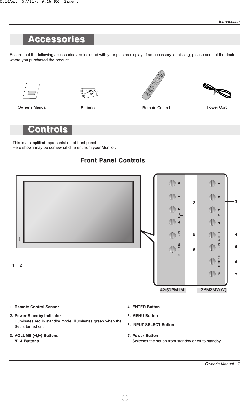
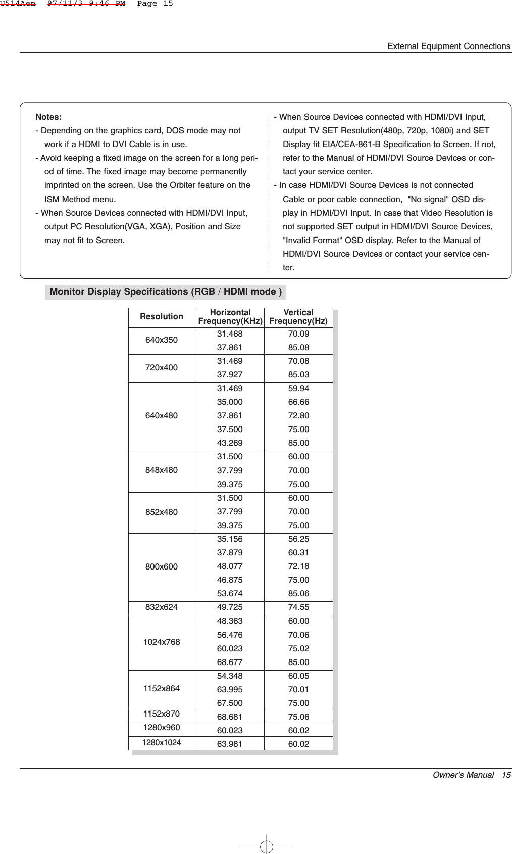
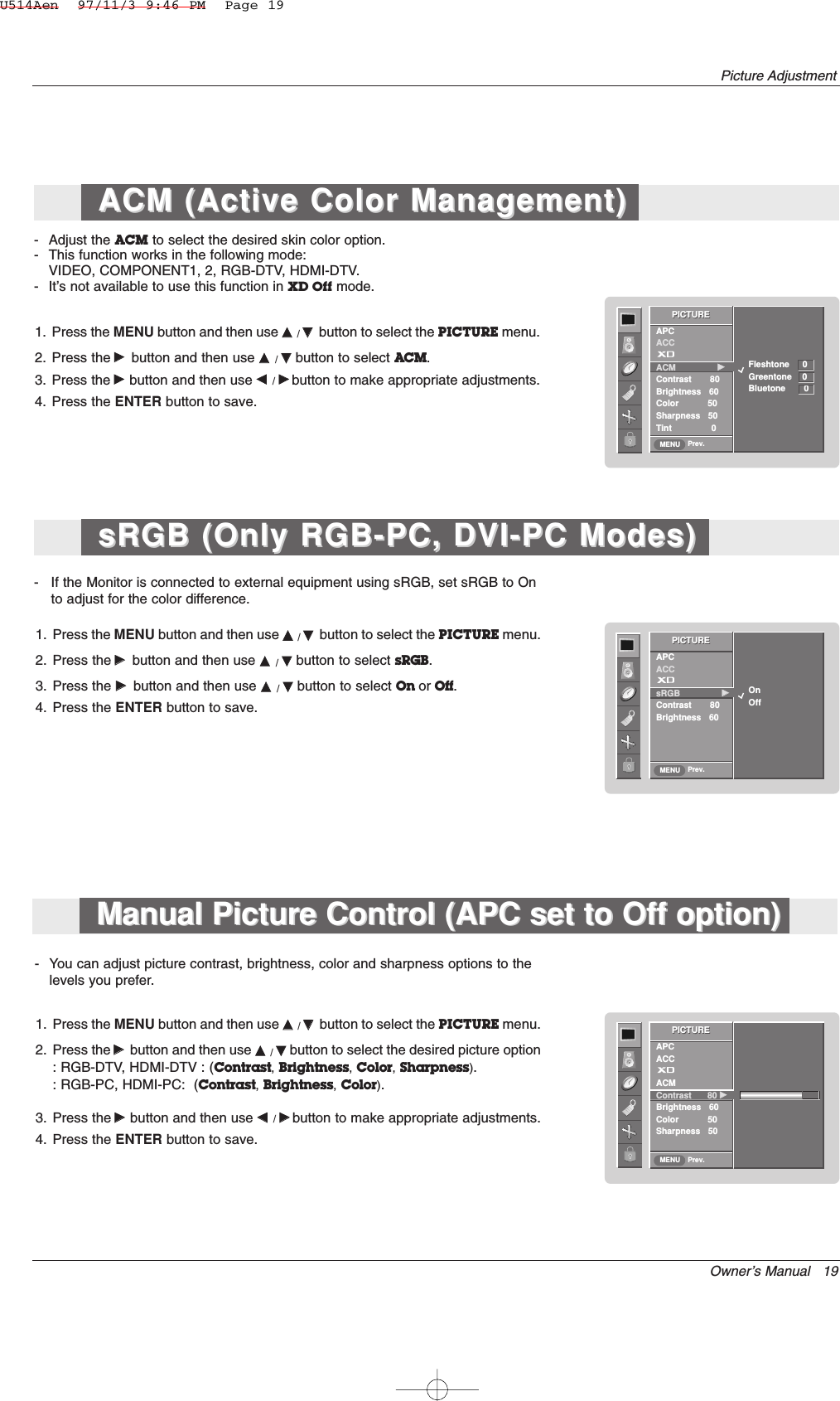
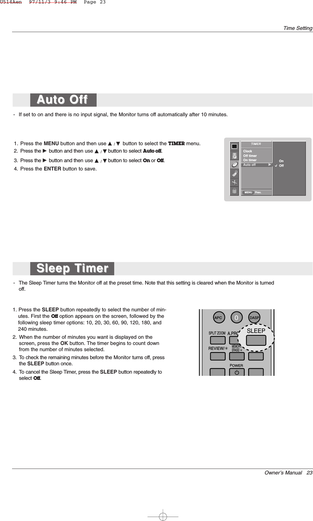
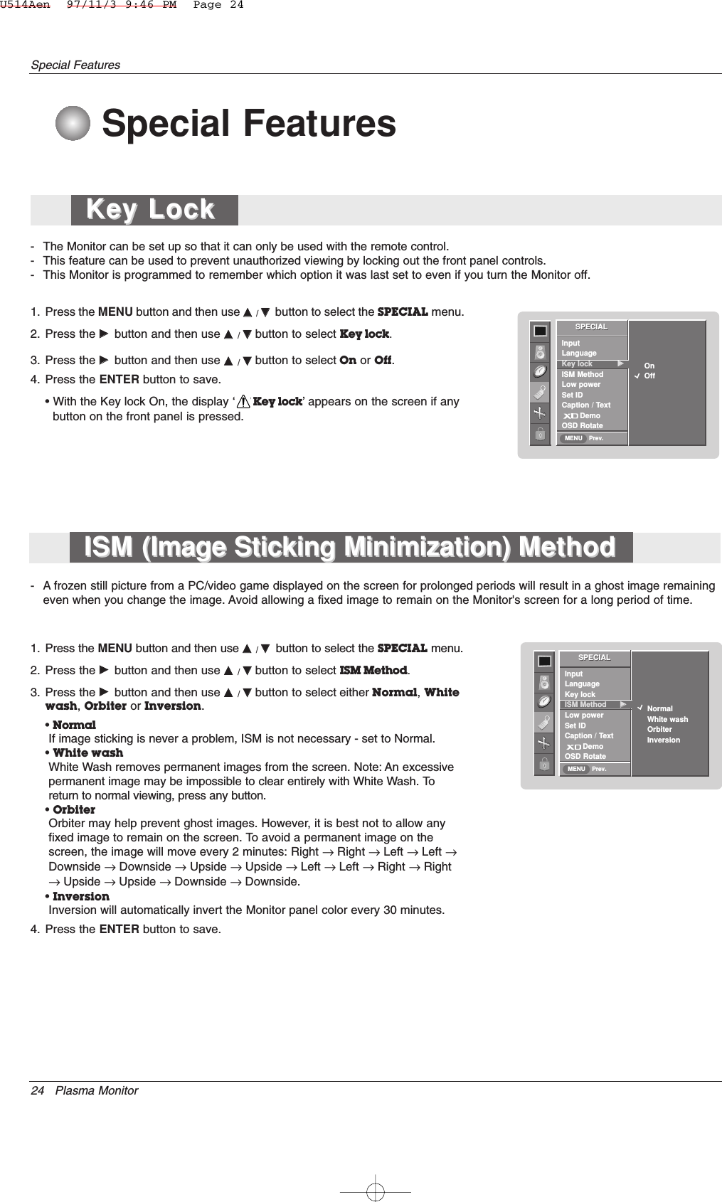
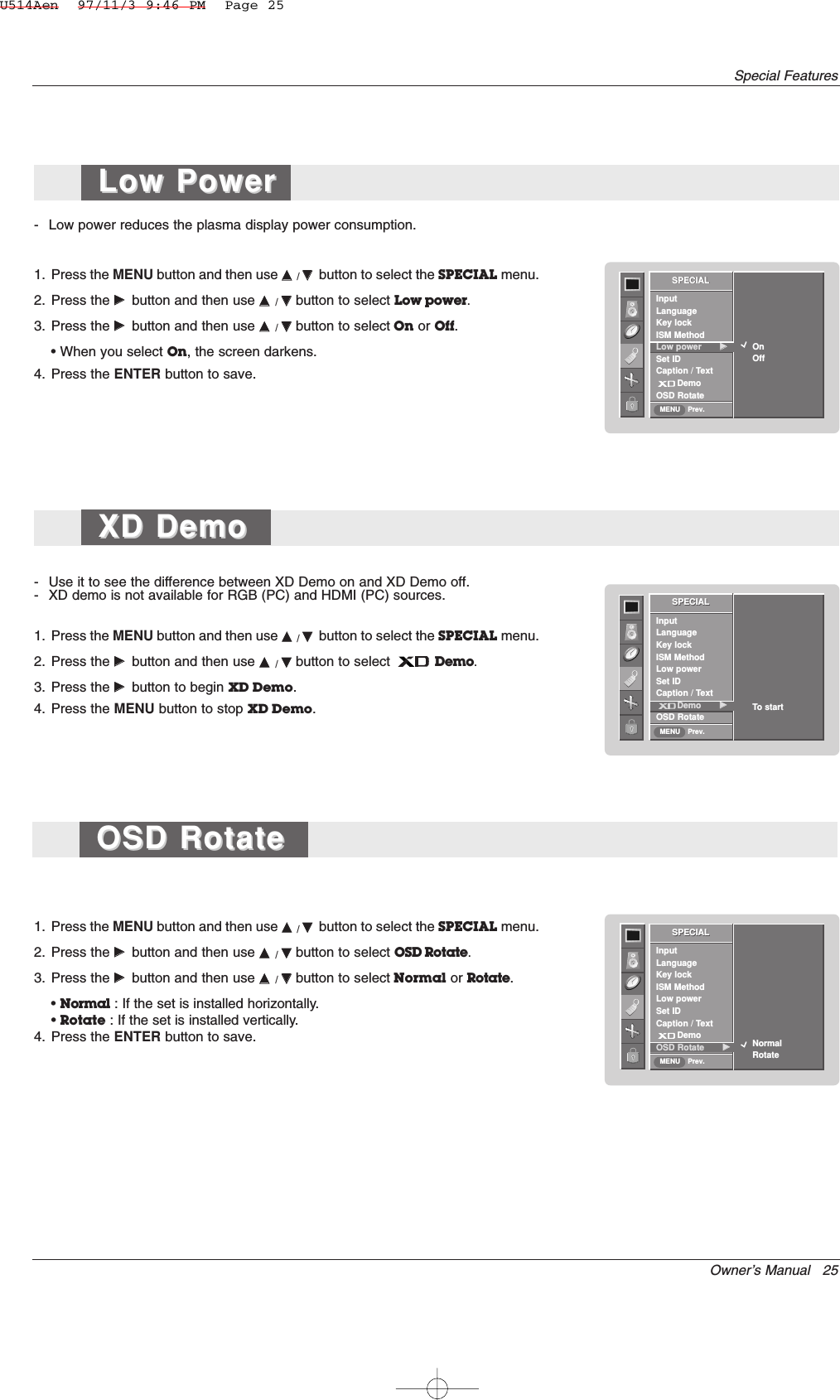
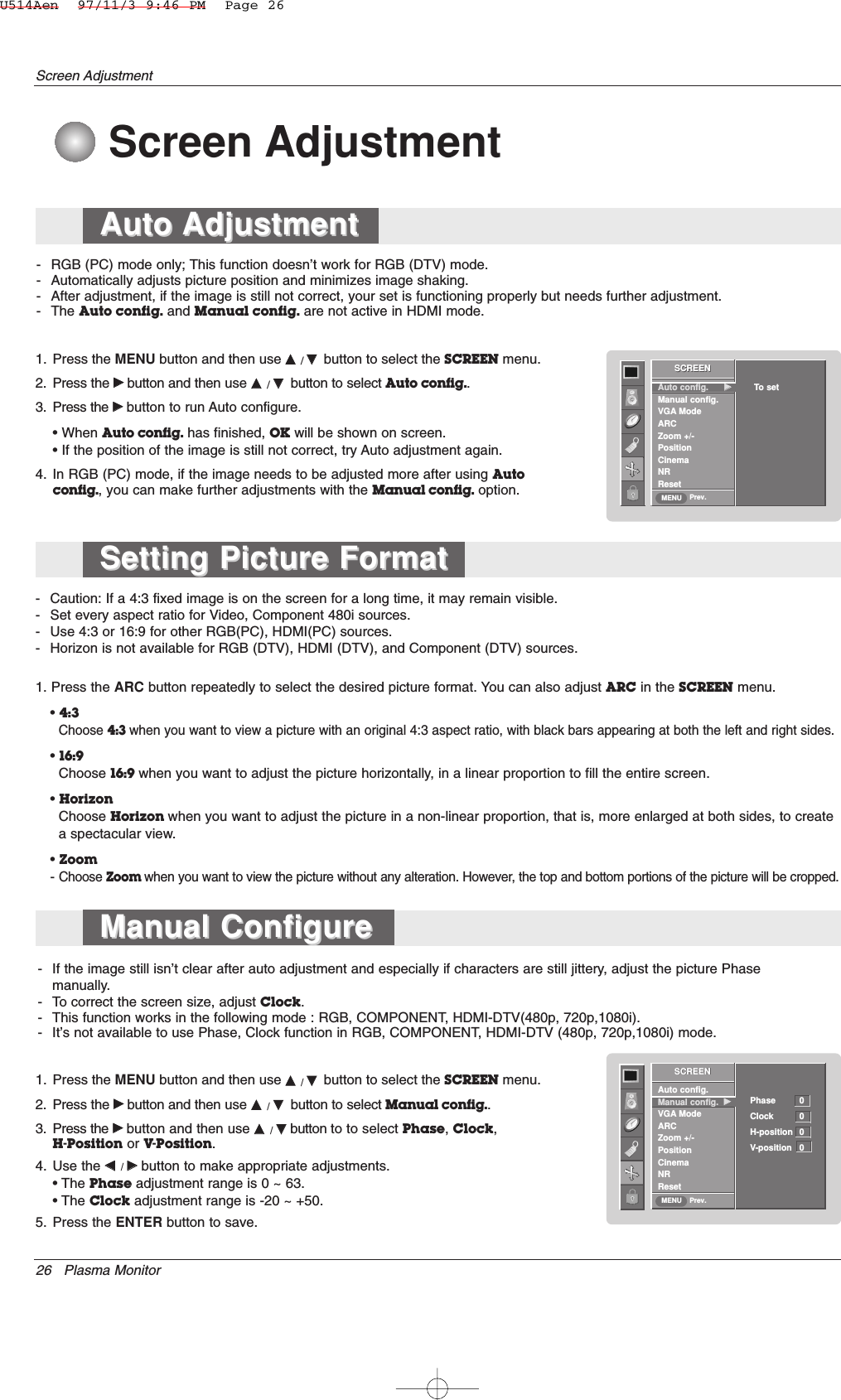
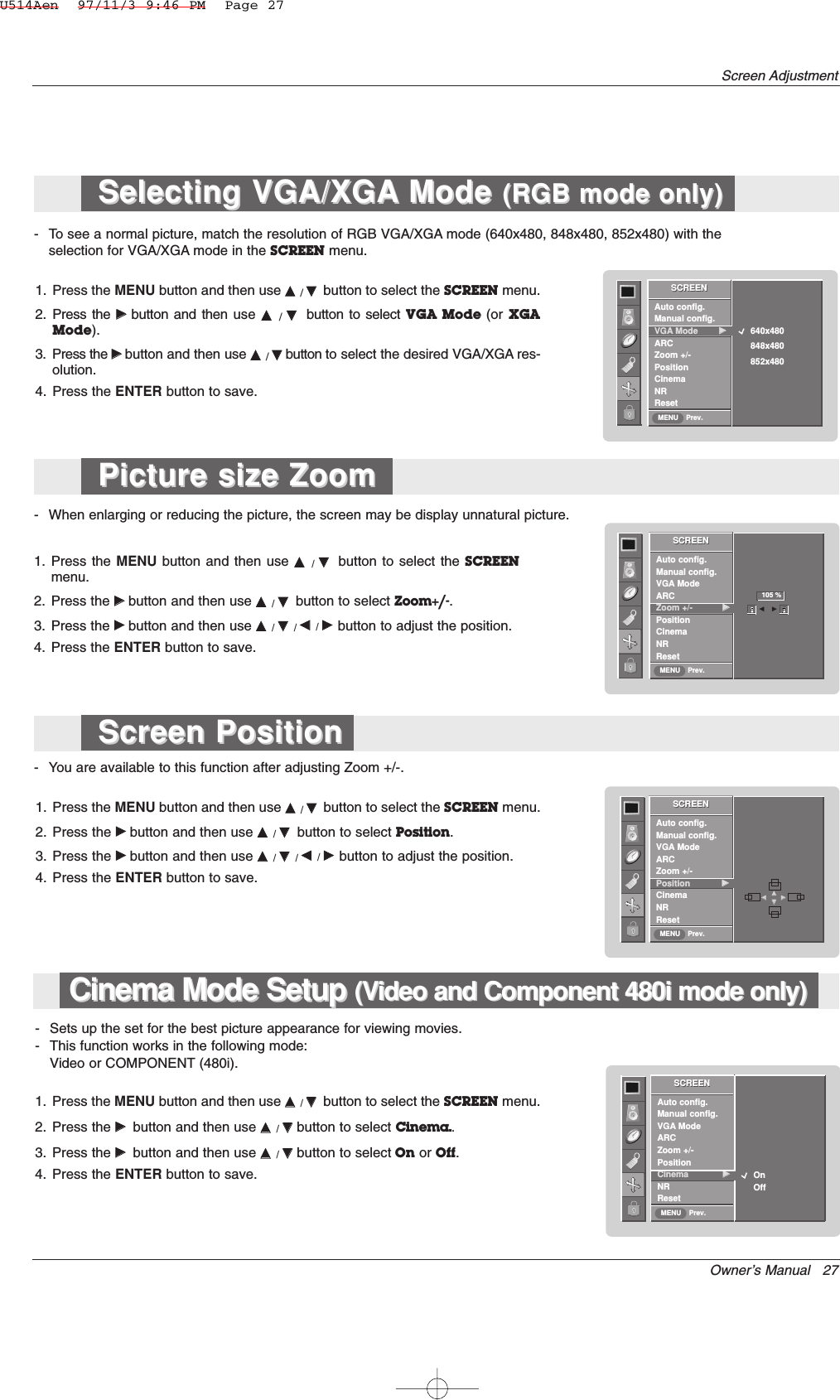
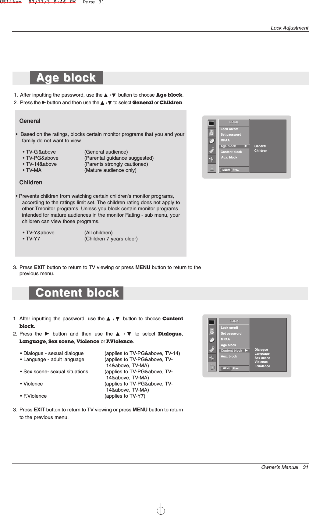
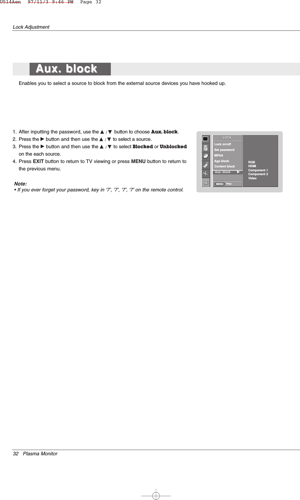
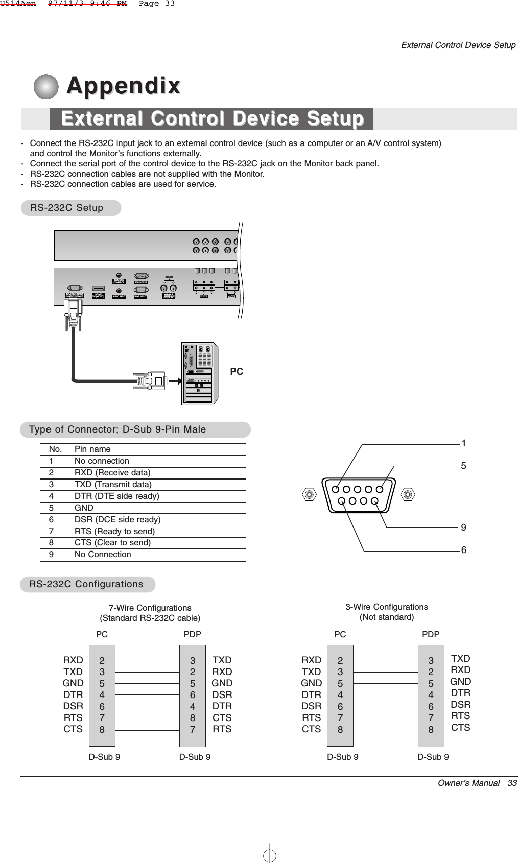
![34 Plasma MonitorExternal Control Device SetupSet IDSet ID- Use this function to specify a Monitor ID number. - Refer to ‘Real Data Mapping 1’. See page 36.1. Press the MENU button and then use DD /EEbutton to select the SPECIAL menu.2. Press the GGbutton and then use DD /EEbutton to select Set ID.3. Press the GGbutton and then use F / Gbutton to adjust Set ID to choose thedesired Monitor ID number. The adjustment range of Set ID is 1 ~ 99.4. Press the ENTER button to save.Transmission* [Command 1] : First command to control PDP set.(j, k, m or x)* [Command 2] : Second command to control PDP set.* [Set ID] : You can adjust the set ID to choose desired monitor ID number in special menu.Adjustment range is 1 ~ 99. When selecting Set ID ‘0’, every connected PDP set is controlled.Set ID is indicated as decimal (1~99) onmenu and as Hexa decimal (0x0~0x63)on transmission/receiving protocol.* [DATA] : To transmit command data.Transmit ‘FF’data to read status of command.* [Cr] : Carriage ReturnASCII code ‘0x0D’* [ ] : ASCII code ‘space (0x20)’[Command1][Command2][ ][Set ID][ ][Data][Cr]OK Acknowledgement* The Monitor transmits ACK (acknowledgement) based onthis format when receiving normal data. At this time, if thedata is data read mode, it indicates present status data. Ifthe data is data write mode, it returns the data of the PCcomputer.[Command2][ ][Set ID][ ][OK][Data][x]Error Acknowledgement* The Monitor transmits ACK (acknowledgement) based onthis format when receiving abnormal data from non-viable functions or communication errors.[Command2][ ][Set ID][ ][NG][Data][x]Transmission / Receiving ProtocolCommand Reference List*When setting the 22 ~ 27, a menu doesn’t display on screen.Data 1: Illegal Code2: not support function3: Wait more time01. Power k a 0 ~ 102. Input Select k b 0 ~ 503. Aspect Ratio k c Refer to p. 3704. Screen Mute k d 0 ~ 105. Volume Mute k e 0 ~ 106. Volume Control k f 0 ~ 6407. Contrast k g 0 ~ 6408. Brightness k h 0 ~ 6409. Color k i 0 ~ 6410. Tint (option) k j 0 ~ 6411. Sharpness k k 0 ~ 6412. OSD Select k l 0 ~ 113. Remote control lock modek m 0 ~ 114. Split Zoom k p 0 ~ 9915. Treble k r 0 ~ 6416. Bass k s 0 ~ 6417. Balance k t 0 ~ 6418. Color Temperature (ACC)k u 0 ~ 319. Red Adjustment k v 0 ~ 5020. Green Adjustment k w 0 ~ 5021. Blue Adjustment k $ 0 ~ 5022. Abnormal Status k z 0 ~ a23. ISM Method j p 0 ~ 324. Low Power j q 0 ~ 125. Orbiter Time Setting j r 1 ~ FE26. Orbiter Pixel Setting j s 1 ~ 327. Auto Configure j u 128. Key m c Key CodeCOMMAND 1 COMMAND 2 DATA(Hexadecimal)• Baud rate : 9600 bps (UART)• Data length : 8 bits• Parity : None* Use a crossed (reverse) cable.• Stop bit : 1 bit• Communication code : ASCII codeCommunication ParametersSPECIALPrev.InputLanguageKey lockISM Method GGLow powerSet IDCaption / TextDemoOSD RotateSPECIALMENU1U514Aen 97/11/3 9:46 PM Page 34](https://usermanual.wiki/LG-Electronics-USA/42PM3MVWUC/User-Guide-615257-Page-34.png)
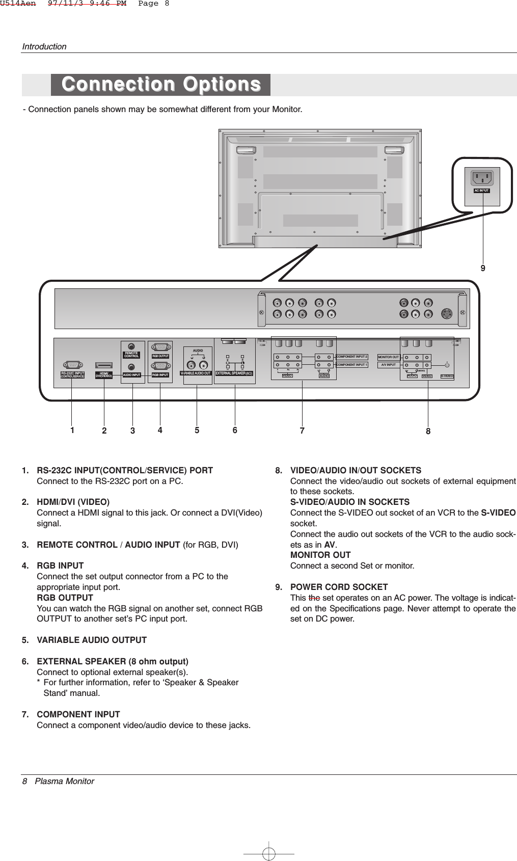
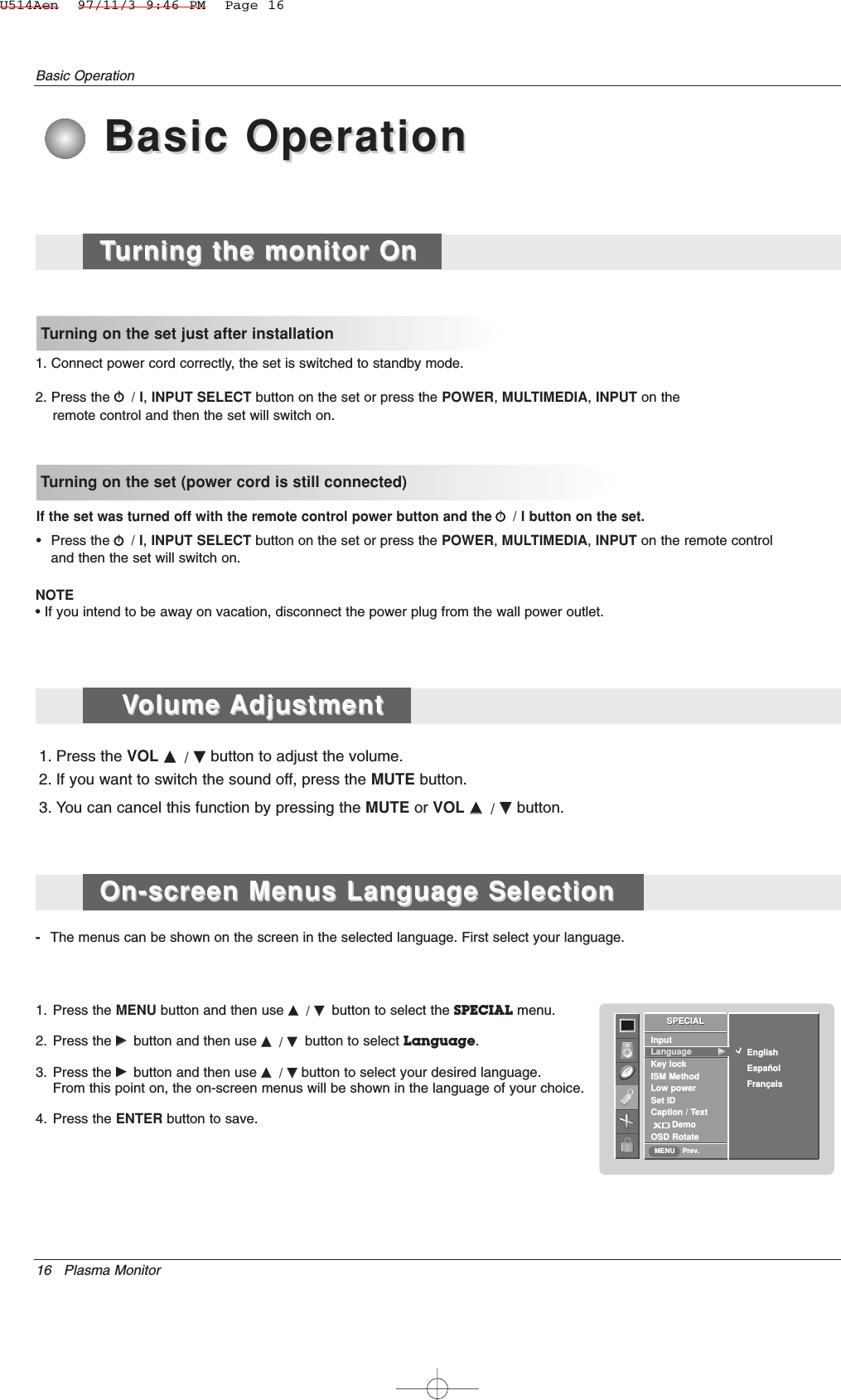
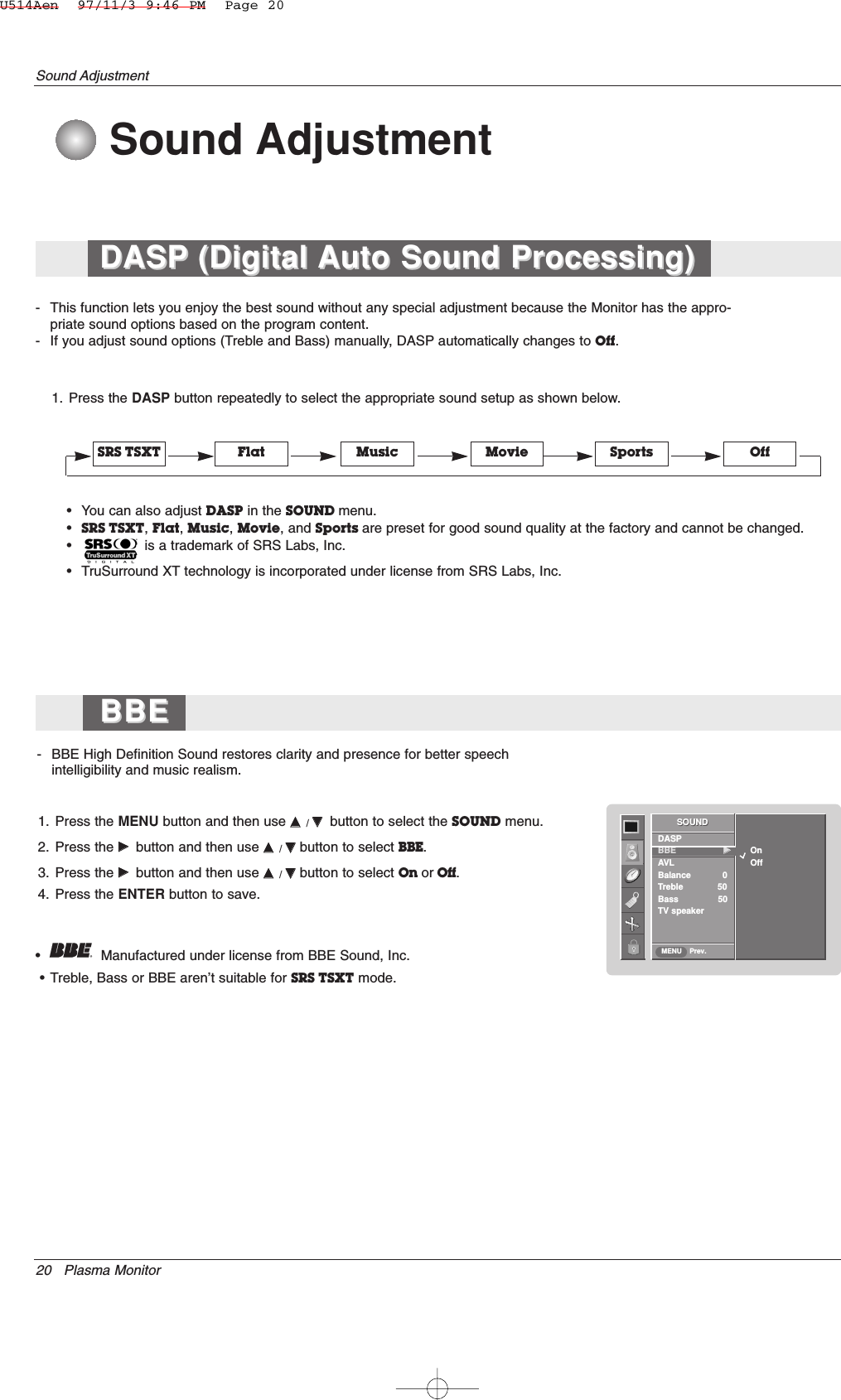
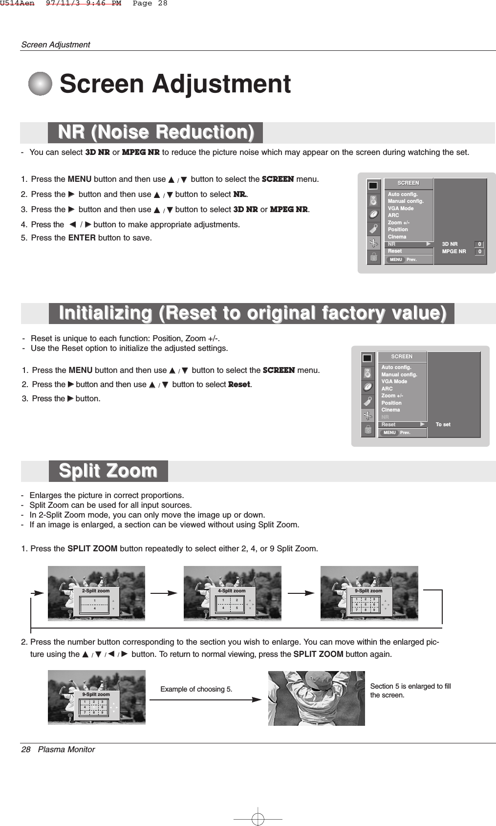
![Owner’s Manual 35External Control Device Setup05. Volume Mute (Command 2 : e)GTo control volume mute on/off.You can also adjust mute using the MUTE button onremote control.TransmissionData 0 : Volume mute off (Volume on)1 : Volume mute on (Volume off)[k][e][ ][Set ID][ ][Data][Cr]Ack[e][ ][Set ID][ ][OK][Data][x]03. Aspect Ratio (Command 2 : c) (Main Picture Size)GTo adjust the screen format. (Main picture format)You can also adjust the screen format using the ARC(Aspect Ratio Control) button on remote control or in theSCREEN menu.TransmissionData 1 : Normal screen (4:3) 2 : Wide screen (16:9) 3 : Horizon4 : Zoom[k][c][ ][Set ID][ ][Data][Cr]Ack* Using the PC input, you select either 16:9 or 4:3 screenaspect ratio.[c][ ][Set ID][ ][OK][Data][x]04. Screen Mute (Command 2 : d)GTo select screen mute on/off.TransmissionData 0 : Screen mute off (Picture on)1 : Screen mute on (Picture off)[k][d][ ][Set ID][ ][Data][Cr]Ack[d][ ][Set ID][ ][OK][Data][x]06. Volume Control (Command 2 : f)GTo adjust volume.You can also adjust volume with the volume buttonson remote control.TransmissionData Min : 0 ~ Max : 64* Refer to ‘Real data mapping 1’.[k][f][ ][Set ID][ ][Data][Cr]Ack[f][ ][Set ID][ ][OK][Data][x]02. Input Select (Command 2 : b)GTo select input source for the monitor. You can also select an input source using the INPUT but-ton on the Monitor's remote control.TransmissionData 0 : RGB1 : HDMI2 : Video4 : Component15 : Component2[k][b][ ][Set ID][ ][Data][Cr]Ack[b][ ][Set ID][ ][OK][Data][x]01. Power (Command2:a)GTo control Power On/Off of the monitor.TransmissionData 0 : Power Off 1 : Power On[k][a][ ][Set ID][ ][Data][Cr]Ack[a][ ][Set ID][ ][OK][Data][x]GTo show Power On/Off.Transmission[k][a][ ][Set ID][ ][FF][Cr]Ack* In like manner, if other functions transmit ‘0xFF’databased on this format, Acknowledgement data feed backpresents status about each function.[a][ ][Set ID][ ][OK][Data][x]* Real data mapping 10 : Step 0A : Step 10 (Set ID 10)F : Step 15 (Set ID 15)10 : Step 16 (Set ID 16)64 : Step 1006E : Step 11073 : Step 11574 : Step 116C7 : Step 199* Real data mapping 20 : -401 : -392 : -3828 : 04E : +384F : +3950 : +40U514Aen 97/11/3 9:46 PM Page 35](https://usermanual.wiki/LG-Electronics-USA/42PM3MVWUC/User-Guide-615257-Page-35.png)
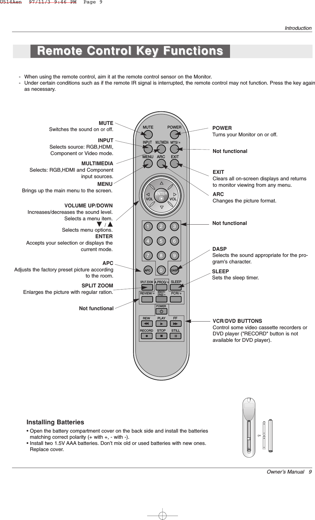
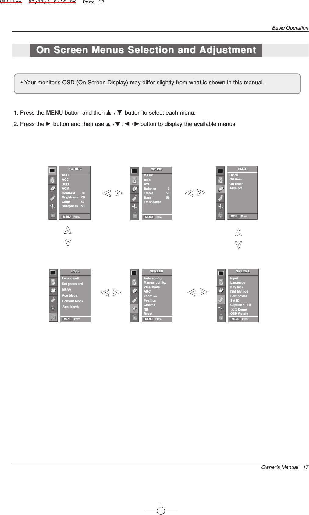
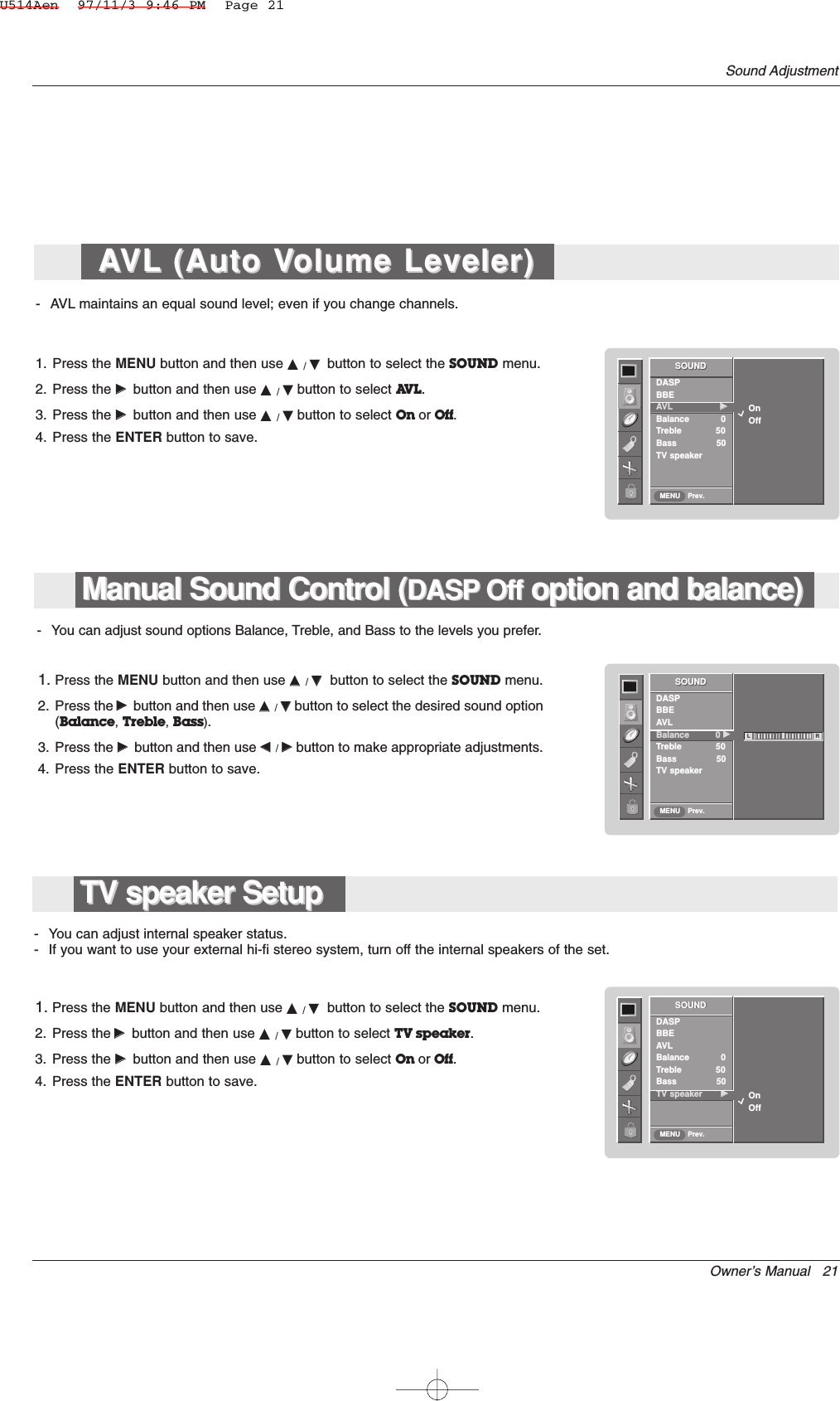
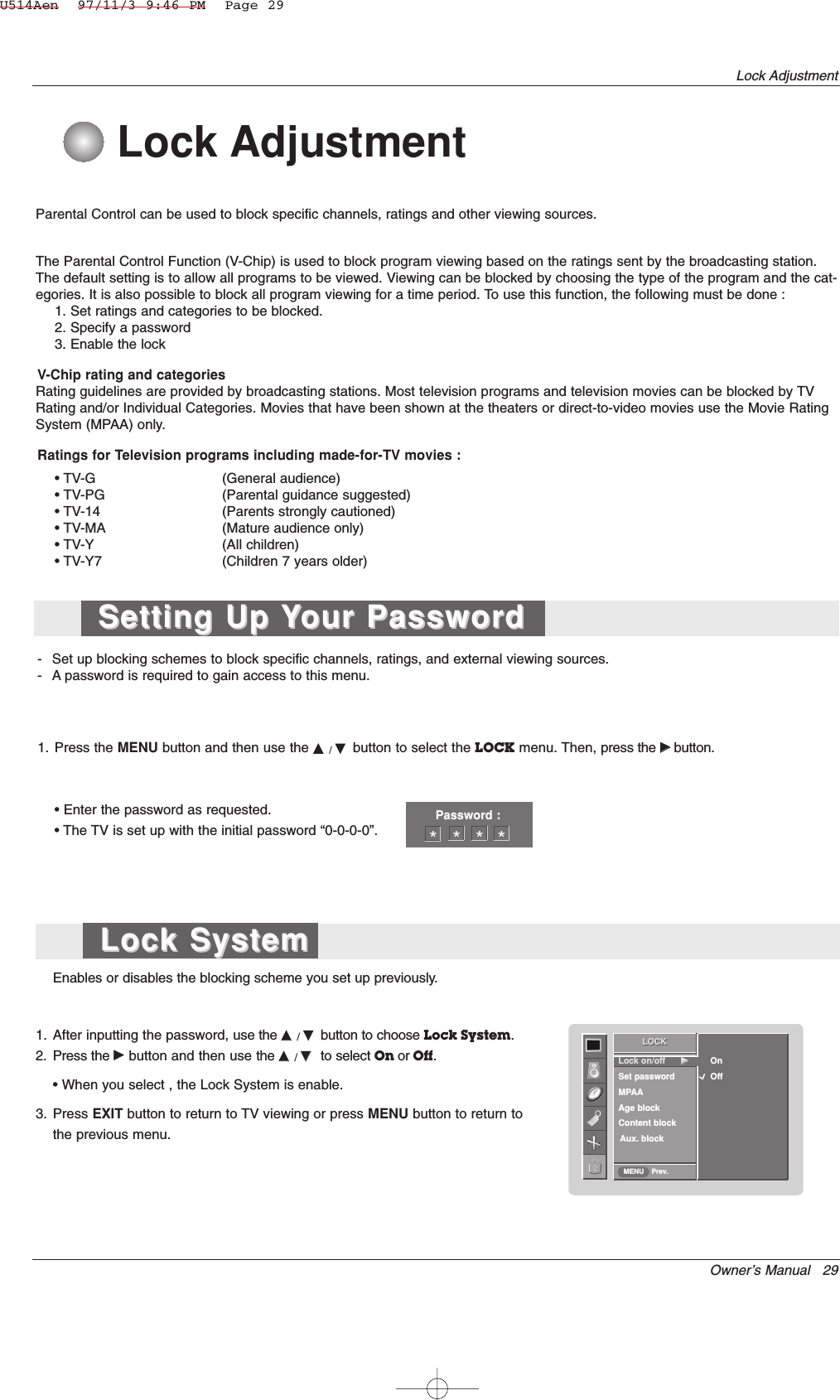
![36 Plasma MonitorExternal Control Device Setup07. Contrast (Command 2 : g)GTo adjust screen contrast. You can also adjust contrast in the PICTURE menu.TransmissionData Min : 0 ~ Max : 64* Refer to ‘Real data mapping 1’. See page 36.[k][g][ ][Set ID][ ][Data][Cr]Ack[g][ ][Set ID][ ][OK][Data][x]08. Brightness (Command 2 : h)GTo adjust screen brightness.You can also adjust brightness in the PICTURE menu.TransmissionData Min : 0 ~ Max : 64* Refer to ‘Real data mapping 1’. See page 36.[k][h][ ][Set ID][ ][Data][Cr]Ack[h][ ][Set ID][ ][OK][Data][x]13. Remote control lock mode (Command 2 : m)GTo lock the front panel controls on the monitor and remotecontrol.Transmission[k][m][ ][Set ID][ ][Data][Cr]AckData 0 : Lock off 1 : Lock on* If you’re not using the remote control, use this mode.When main power is on/off, external control lock isreleased.[m][ ][Set ID][ ][OK][Data][x]12. OSD Select (Command 2 : l)GTo select OSD (On Screen Display) on/off when con-trolling remotely.Transmission[k][l][ ][Set ID][ ][Data][Cr]AckData 0 : OSD off 1 : OSD on[l][ ][Set ID][ ][OK][Data][x]09. Color (Command 2 : i)GTo adjust the screen color.You can also adjust color in the PICTURE menu.TransmissionData Min : 0 ~ Max : 64* Refer to ‘Real data mapping 1’. See page 36.[k][i][ ][Set ID][ ][Data][Cr]Ack[i][ ][Set ID][ ][OK][Data][x]10. Tint (Command 2 : j) (option)GTo adjust the screen tint.You can also adjust tint in the PICTURE menu.TransmissionData Red : 0 ~ Green : 64* Refer to ‘Real data mapping 1’. See page 36.[k][j][ ][Set ID][ ][Data][Cr]Ack[j][ ][Set ID][ ][OK][Data][x]GTo adjust the screen sharpness.You can also adjust sharpness in the PICTURE menu.Transmission11. Sharpness (Command 2 : k)Data Min : 0 ~ Max : 64* Refer to ‘Real data mapping 1’. See page 36.[k][k][ ][Set ID][ ][Data][Cr]Ack[k][ ][Set ID][ ][OK][Data][x]14. Split Zoom (Command2:p)GTo operate split zoom function and select the splitzoom section number.TransmissionData Min: 0 ~ Max:99•Refer to ‘Real data mapping 2’.[k][p][ ][Set ID][ ][Data][Cr]Acknowledgement[p][ ][Set ID][ ][OK][Data][x]* Real data mapping 20 : Reset split zoom21: Selection 1 of 2 split zoom24: Selection 4 of 2 split zoom41: Selection 1 of 4 split zoom42: Selection 2 of 4 split zoom44: Selection 4 of 4 split zoom45: Selection 5 of 4 split zoom91: Selection 1 of 9 split zoom99: Selection 9 of 9 split zoomU514Aen 97/11/3 9:46 PM Page 36](https://usermanual.wiki/LG-Electronics-USA/42PM3MVWUC/User-Guide-615257-Page-36.png)
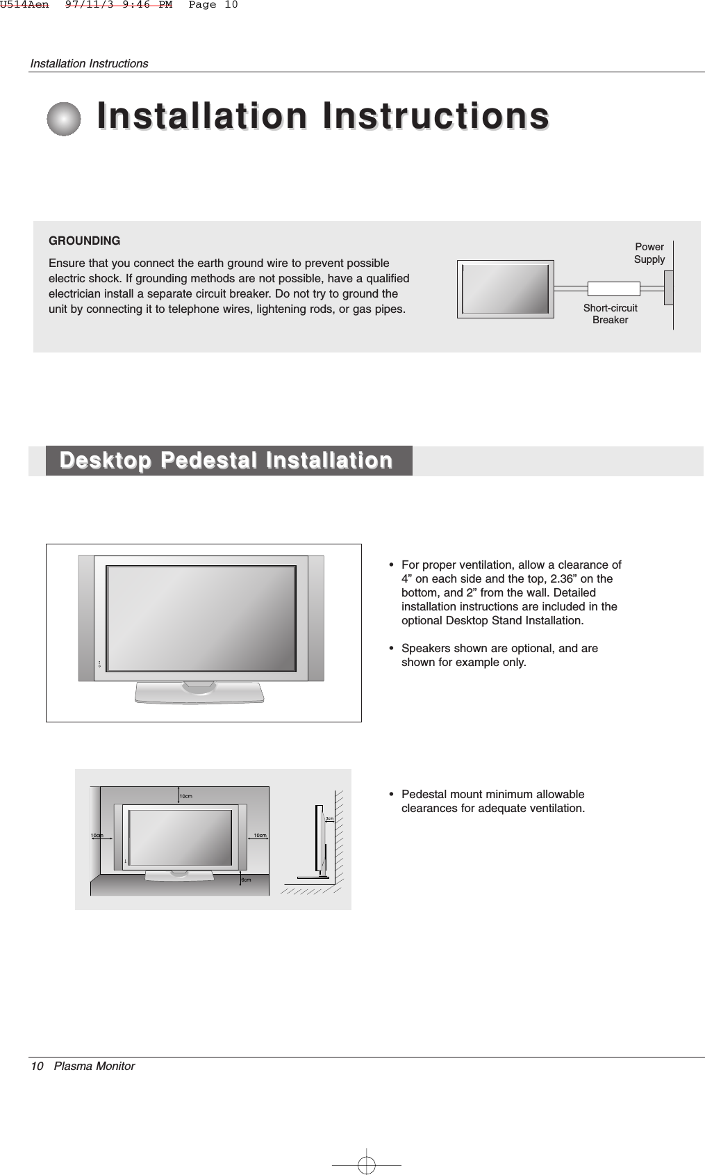
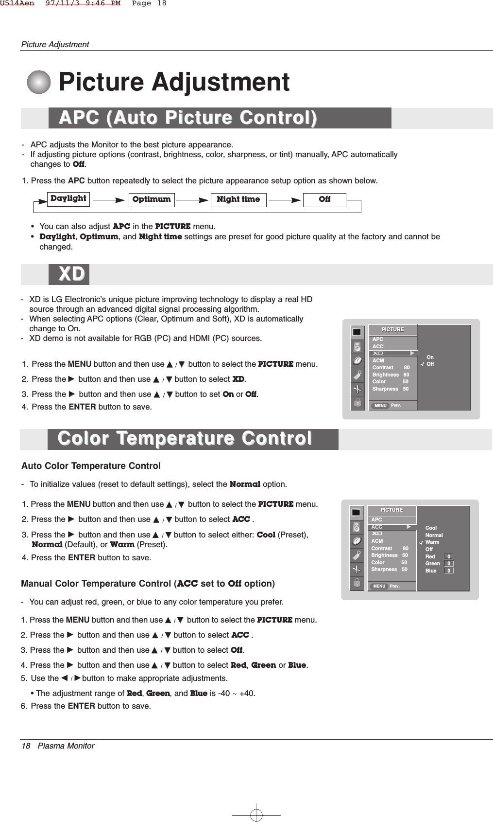
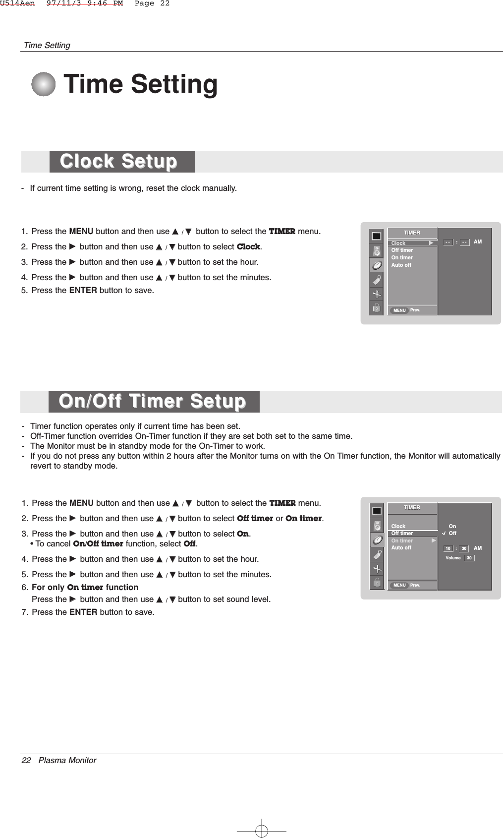
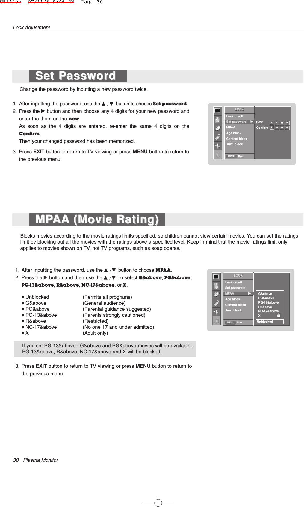
![Owner’s Manual 37External Control Device Setup20. Green Adjustment (Command 2 : w)GTo adjust green in color temperature.TransmissionData Min : 0 ~ Max : 50* Refer to ‘Real data mapping 2’. See page 36.[k][w][ ][Set ID][ ][Data][Cr]Ack[w][ ][Set ID][ ][OK][Data][x]21. Blue Adjustment (Command 2 : $)GTo adjust blue in color temperature.TransmissionData Min : 0 ~ Max : 50* Refer to ‘Real data mapping 2’. See page 36.[k][$][ ][Set ID][ ][Data][Cr]Ack[$][ ][Set ID][ ][OK][Data][x]19. Red Adjustment (Command 2 : v)GTo adjust red in color temperature.TransmissionData Min : 0 ~ Max : 50* Refer to ‘Real data mapping 2’. See page 36.[k][v][ ][Set ID][ ][Data][Cr]Ack[v][ ][Set ID][ ][OK][Data][x]18. Color Temperature (Command 2 : u)GTo adjust color temperature.You can also adjust ACC in the PICTURE menu.TransmissionData 0: Cool 1: Normal 2: Warm 3: Off[k][u][ ][Set ID][ ][Data][Cr]Ack[u][ ][Set ID][ ][OK][Data][x]16. Bass (Command 2 : s)GTo adjust bass.You can also adjust bass in the SOUND menu.TransmissionData Min : 0 ~ Max : 64* Refer to ‘Real data mapping 1’. See page 36.[k][s][ ][Set ID][ ][Data][Cr]Ack[s][ ][Set ID][ ][OK][Data][x]15. Treble (Command 2 :r)GTo adjust treble.You can also adjust treble in the SOUND menu.TransmissionData Min : 0 ~ Max : 64* Refer to ‘Real data mapping 1’. See page 36.[k][r][ ][Set ID][ ][Data][Cr]Ack[r][ ][Set ID][ ][OK][Data][x]17. Balance (Command 2 : t)GTo adjust balance.You can also adjust balance in the SOUND menu.TransmissionData Min : 0 ~ Max : 64* Refer to ‘Real data mapping 1’. See page 36.[k][t][ ][Set ID][ ][Data][Cr]Ack[t][ ][Set ID][ ][OK][Data][x]U514Aen 97/11/3 9:46 PM Page 37](https://usermanual.wiki/LG-Electronics-USA/42PM3MVWUC/User-Guide-615257-Page-37.png)
![38 Plasma MonitorExternal Control Device Setup22. Abnormal State (Command 2 : z)GTo recognize an abnormal state.TransmissionData FF : ReadData 0: Normal (Power on and signal exist)1: No signal (Power on)2: Turn the monitor off by remote control3: Turn the monitor off by sleep time function4: Turn the monitor off by RS-232C function5: 5V down6: AC down7: Turn the monitor off by Fan Alarm function (option)8: Turn the monitor off by Off time function9: Turn the monitor off by Auto sleep functiona: Turn the monitor off by AV board detect* This function is “read only”.[k][z][ ][Set ID][ ][FF][ ][Cr]Ack[z][ ][Set ID][ ][OK][Data][x]23. ISM Method (Command 1 : j, Command 2 : p)GTo control the ISM method. You can also adjust ISMMethod in SPECIAL menu.TransmissionData 0 : Normal Mode1 : White Wash2 : Orbiter3 : Inversion[j][p][ ][Set ID][ ][Data][Cr]Ack[p][ ][Set ID][ ][OK][Data][x]24. Low Power(Command 1 : j, Command 2 : q)GTo reduce the power consumption of the monitor. Youcan also adjust Low Power in SPECIAL menu.TransmissionData 0 : Off1 : On[j][q][ ][Set ID][ ][Data][ ][Cr]Ack[q][ ][Set ID][ ][OK][Data][x]25. Orbiter Time Setting(Command 1 : j, Command 2 : r)GTo adjust orbiter operation time term.TransmissionData Min: 1 ~ Max: FE* Refer to ‘Real data mapping 1’. See page 36.[j][r][ ][Set ID][ ][Data][ ][Cr]Ack[r][ ][Set ID][ ][OK][Data][x]26. Orbiter Pixel Setting(Command 1 : j, Command 2 : s)GTo adjust pixel number in orbiter function.TransmissionData Min: 1 ~ Max: 3* Refer to ‘Real data mapping 1’. See page 36.[j][s][ ][Set ID][ ][Data][Cr]Ack[s][ ][Set ID][ ][OK][Data][x]27. Auto Configure(Command 1 : j, Command 2 : u)GTo adjust picture position and minimize image shakingautomatically. It works only in RGB (PC) mode.TransmissionData 1: To set[j][u][ ][Set ID][ ][Data][Cr]Ack[u][ ][Set ID][ ][OK][Data][x]28. Key(Command 1 : m, Command 2 : c)GTo send IR remote key code.TransmissionData Key code - Refer to page 37.[m][c][ ][Set ID][ ][Data][Cr]Ack[c][ ][Set ID][ ][OK][Data][x]U514Aen 97/11/3 9:46 PM Page 38](https://usermanual.wiki/LG-Electronics-USA/42PM3MVWUC/User-Guide-615257-Page-38.png)