LG Electronics USA 42PM4MWA PLASMA MONITOR User Manual 42PM4M
LG Electronics USA PLASMA MONITOR 42PM4M
Users manual
2 Plasma Monitor
Warning
WARNING:
TO REDUCE THE RISK OF ELECTRIC SHOCK DO NOT REMOVE COVER (OR BACK). NO USER
SERVICEABLE PARTS INSIDE. REFER TO QUALIFIED SERVICE PERSONNEL.
The lightning flash with arrowhead symbol, within an equilateral triangle, is intended to alert the user to
the presence of uninsulated “dangerous voltage” within the product’s enclosure that may be of suffi-
cient magnitude to constitute a risk of electric shock to persons.
The exclamation point within an equilateral triangle is intended to alert the user to the presence of
important operating and maintenance (servicing) instructions in the literature accompanying the appli-
ance.
WARNING:
TO PREVENT FIRE OR SHOCK HAZARDS, DO NOT EXPOSE THIS PRODUCT TO RAIN OR MOISTURE.
FCC NOTICE
• A Class B digital device
This equipment has been tested and found to comply with the limits for a Class B digital device, pursuant to Part
15 of the FCC Rules. These limits are designed to provide reasonable protection against harmful interference in
a residential installation. This equipment generates, uses and can radiate radio frequency energy and, if not
installed and used in accordance with the instructions, may cause harmful interference to radio communications.
However, there is no guarantee that interference will not occur in a particular installation. If this equipment does
cause harmful interference to radio or television reception, which can be determined by turning the equipment off
and on, the user is encouraged to try to correct the interference by one or more of the following measures:
- Reorient or relocate the receiving antenna.
- Increase the separation between the equipment and receiver.
- Connect the equipment into an outlet on a circuit different from that to which the receiver is connected.
- Consult the dealer or an experienced radio/TV technician for help.
• Any changes or modifications not expressly approved by the party responsible for compli-
ance could void the user’s warranty.
CAUTION:
Do not attempt to modify this product in any way without written authorization from LG Electronics. Unauthorized mod-
ification could void the user’s warranty.
COMPLIANCE:
The responsible party for this product’s compliance is:
LG Electronics U.S.A., Inc
1000 Sylvan Avenue, Englewood Cliffs, NJ 07632
1-800-243-0000
http://www.lgusa.com
WARNING
RISK OF ELECTRIC SHOCK
DO NOT OPEN
/CAUTION
W
Warning
arning
Owner’s Manual 3
Safety Instructions
Safety Instructions
Safety Instructions
IMPORTANT SAFETY INSTRUCTIONS
Important safety instructions shall be provided with each apparatus. This information shall be given in a separate booklet
or sheet, or be located before any operating instructions in an instruction for installation for use and supplied with the appa-
ratus.
This information shall be given in a language acceptable to the country where the apparatus is intended to be used.
The important safety instructions shall be entitled “Important Safety Instructions”. The following safety instructions shall be
included where applicable, and, when used, shall be verbatim as follows. Additional safety information may be included by
adding statements after the end of the following safety instruction list. At the manufacturer’s option, a picture or drawing that
illustrates the intent of a specific safety instruction may be placed immediately adjacent to that safety instruction :
1. Read these instructions.
2. Keep these instructions.
3. Heed all warnings.
4. Follow all instructions.
5. Do not use this apparatus near water.
6. Clean only with dry cloth.
7. Do not block any ventilation openings. Install in accor-
dance with the manufacturer’s instructions.
8. Do not install near any heat sources such as radiators,
heat registers, stoves, or other apparatus (including ampli-
fiers)that produce heat.
9. Do not defeat the safety purpose of the polarized or
grounding-type plug. A polarized plug has two blades with
one wider than the other. A grounding type plug has two
blades and a third grounding prong, The wide blade or the
third prong are provided for your safety. If the provided plug
does not fit into your outlet, consult an electrician for replace-
ment of the obsolete outlet.
10. Protect the power cord from being walked on or pinched
particularly at plugs, convenience receptacles, and the point
where they exit from the apparatus.
11. Only use attachments/accessories specified by the man-
ufacturer.
Owner's Manual
4 Plasma Monitor
Safety Instructions
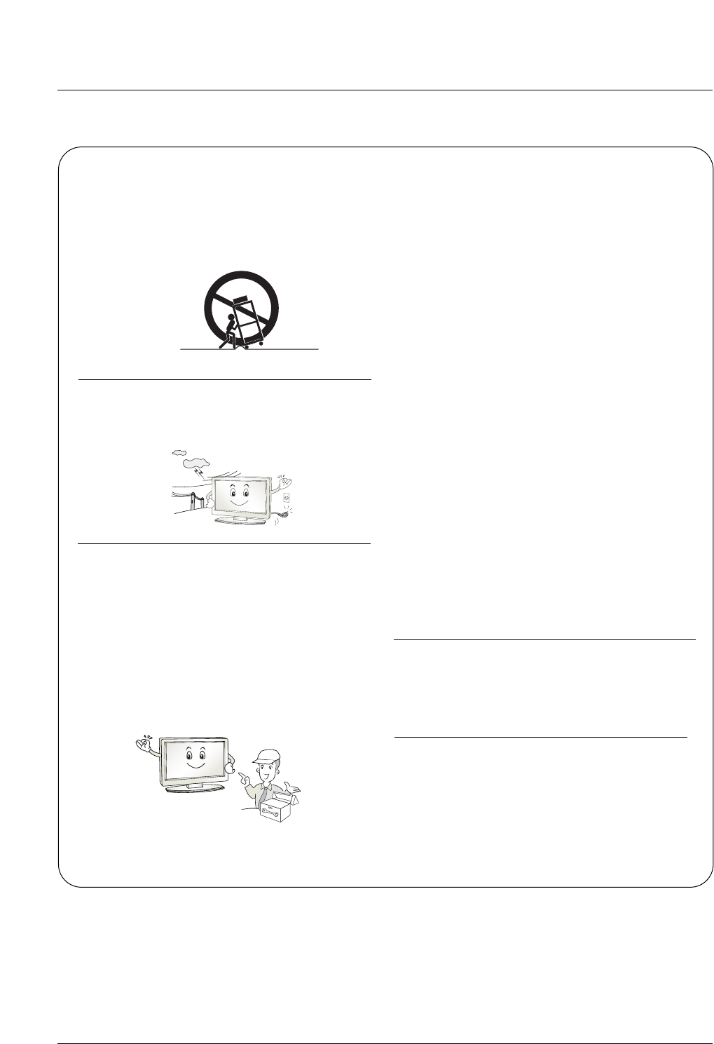
12. Use only with the cart, stand, tripod, bracket, or table
specified by the manufacturer, or sold with the apparatus.
When a cart is used, use caution when moving the
cart/apparatus combination to avoid injury from tip-over.
13. Unplug this apparatus during lightning storms or when
unused for long periods of time.
14. Refer all servicing to qualified service personnel.
Servicing is required when the apparatus has been dam-
aged in any way, such as power-supply cord or plug is dam-
aged, liquid has been spilled or objects have fallen into the
apparatus, the apparatus has exposed to rain or moisture,
does not operate normally, or has been dropped.
15. CAUTION concerning the Power Cord :
Most appliances recommend they be placed upon a dedi-
cated circuit; that is, a single outlet circuit which powers only
that appliance and has no additional outlets or branch cir-
cuits. Check the specification page of this owner's manual to
be certain.
Do not overload wall outlets. Overloaded wall outlets, loose
or damaged wall outlets, extension cords, frayed power
cords, or damaged or cracked wire insulation are dangerous.
Any of these conditions could result in electric shock or fire.
Periodically examine the cord of your
appliance, and if its appearance indicates damage or deteri-
oration, unplug it, discontinue use of the appliance, and have
the cord replaced with an exact replacement part by an
authorized servicer.
Protect the power cord from physical or mechanical abuse,
such as being twisted, kinked, pinched, closed in a door, or
walked upon. Pay particular attention to plugs, wall outlets,
and the point where the cord exits the appliance.
16. Outdoor Use Marking :
WARNING - To Reduce The Risk Of Fire Or Electric Shock,
Do Not Expose This Appliance To Rain Or Moisture.
17. Wet Location Marking :
Apparatus shall not be exposed to dripping or splashing and
no objects filled with liquids, such as vases, shall be placed
on the apparatus.
PORTABLE CART WARNING

Owner’s Manual 5
Contents
Safety Instructions . . . . . . . . . . . . . . . . . . . . . . . . . . . . .2~4
Introduction
Features Of This monitor . . . . . . . . . . . . . . . . . .6
Accessories . . . . . . . . . . . . . . . . . . . . . . . . . . . .7
Controls and Connection Options . . . . . . . . . .8~9
Remote Control Key Functions . . . . . . . . . . . . .10
Installation
Desktop Pedestal Installation . . . . . . . . . . . . . . . .11
External Equipment Connections
VCR Setup . . . . . . . . . . . . . . . . . . . . . . . . . . . .12
Cable TV Setup . . . . . . . . . . . . . . . . . . . . . . . .13
External A/V Source Setup . . . . . . . . . . . . . . . .13
DVD Setup . . . . . . . . . . . . . . . . . . . . . . . . . . . .14
DTV Setup . . . . . . . . . . . . . . . . . . . . . . . . . . . .15
PC Setup . . . . . . . . . . . . . . . . . . . . . . . . . .16~17
Operation
Turning on the Monitor . . . . . . . . . . . . . . . . . . . . .18
Menu Language Selection . . . . . . . . . . . . . . . . . .18
On Screen Menus Selection . . . . . . . . . . . . . . . . .19
Picture Menu Options
Picture Status Memory (PSM) . . . . . . . . . . . . . .20
Manual Picture Control . . . . . . . . . . . . . . . . . .20
Color Status Memory (PSM) . . . . . . . . . . . . . . .21
Manual Color Temperature Control . . . . . . . . . .21
XD . . . . . . . . . . . . . . . . . . . . . . . . . . . . . . . . . .22
Picture Reset . . . . . . . . . . . . . . . . . . . . . . . . . .22
Advanced - Cinema 3:2 Pull down mode . . . . . .23
Advanced - Black level . . . . . . . . . . . . . . . . . . .23
Sound Menu Options
Sound Status Memory (SSM) . . . . . . . . . . . . . .24
Manual Sound Control . . . . . . . . . . . . . . . . . . .24
AVL (Auto Volume Leveler) . . . . . . . . . . . . . . . .25
Balance . . . . . . . . . . . . . . . . . . . . . . . . . . . . . .25
TV Speaker on/off setup . . . . . . . . . . . . . . . . . .25
Timer Menu Options
Clock Setup . . . . . . . . . . . . . . . . . . . . . . . . . . .26
On/Off Timer Setup . . . . . . . . . . . . . . . . . . . . .26
Auto Sleep . . . . . . . . . . . . . . . . . . . . . . . . . . . .27
Sleep Timer . . . . . . . . . . . . . . . . . . . . . . . . . . .27
Special Menu Options
Child Lock . . . . . . . . . . . . . . . . . . . . . . . . . . . .28
ISM Method . . . . . . . . . . . . . . . . . . . . . . . . . . .28
Tile mode . . . . . . . . . . . . . . . . . . . . . . . . . . . . .29
Low power . . . . . . . . . . . . . . . . . . . . . . . . . . . .30
XD demo . . . . . . . . . . . . . . . . . . . . . . . . . . . . .30
Screen Menu Options
Auto Adjustment . . . . . . . . . . . . . . . . . . . . . . . .31
Manual Configure . . . . . . . . . . . . . . . . . . . . . . .31
Selecting XGA mode . . . . . . . . . . . . . . . . . . . . .32
Picture Size Control . . . . . . . . . . . . . . . . . . . . .32
Screen Position . . . . . . . . . . . . . . . . . . . . . . . .29
Initializing . . . . . . . . . . . . . . . . . . . . . . . . . . . . .33
External Control Device Setup . . . . . . . . . . . . . . . .34~39
IR Code . . . . . . . . . . . . . . . . . . . . . . . . . . . . . . . . .40~41
Troubleshooting Checklist . . . . . . . . . . . . . . . . . . .42~43
Troubleshooting Checklist . . . . . . . . . . . . . . . . . . . . . .44
Specifications . . . . . . . . . . . . . . . . . . . . . . . . . . . . . . . .45
Contents
Contents
After reading this manual, keep it handy for future reference.

6 Plasma Monitor
Introduction
Introduction
Introduction
Features Of This Monitor
Features Of This Monitor
What is a Plasma Monitor ?
If voltage is applied to gas within glass panels, ultraviolet rays are produced and fused with a fluorescent substance. At that
instant, light is emitted. A Plasma Display is a next generation flat Display using this phenomenon.
160° - Wide angle range of vision
Your flat panel plasma screen offers an exceptionally broad viewing angle -- over 160 degrees. This means that the display is
clear and visible to viewers anywhere in the room.
Wide Screen
The screen of the Plasma Display is 71" so wide that your viewing experience is as if you are in a theater.
Multimedia
Connect your plasma display to a PC and you can use it for conferencing, games, and internet browsing. The Picture-in-Picture
feature allows you to view your PC and video images simultaneously.
Versatile
The light weight and thin size makes it easy to install your plasma display in a variety of locations where conventional TVs would
not fit.
The Plasma Monitor Manufacturing Process: Why minute colored dots may be present on the Plasma
Monitor screen
The Plasma Display Panel which is the display device of this product is composed of 0.9 to 2.2 million cells. A few cell defects will
normally occur in the Plasma Monitor manufacturing process. Several minute colored dots visible on the screen should be accept-
able. This also occurs in other Plasma Monitor manufacturers' products and the tiny dots appearing does not mean that this
Plasma Monitor is defective. Thus a few cell defects are not sufficient cause for the Plasma Monitor to be exchanged or returned.
Our production technology is designed to minimize cell defects during the manufacture and operation of this product.
Cooling Fan Noise
In the same way that a fan is used in a PC computer to keep the CPU (Central Processing Unit) cool, the Plasma Monitor is
equipped with cooling fans to cool the Monitor and improve its reliability. Therefore, a certain level of noise could occur while the
fans are operating and cooling the Plasma Monitor.
The fan noise doesn't have any negative effect on the Plasma Monitor's efficiency or reliability. The noise from these fans is nor-
mal during the operation of this product. We hope you understand that a certain level of noise from the cooling fans is acceptable
and is not sufficient cause for the Plasma Monitor to be exchanged or returned.
Owner’s Manual 7
Introduction
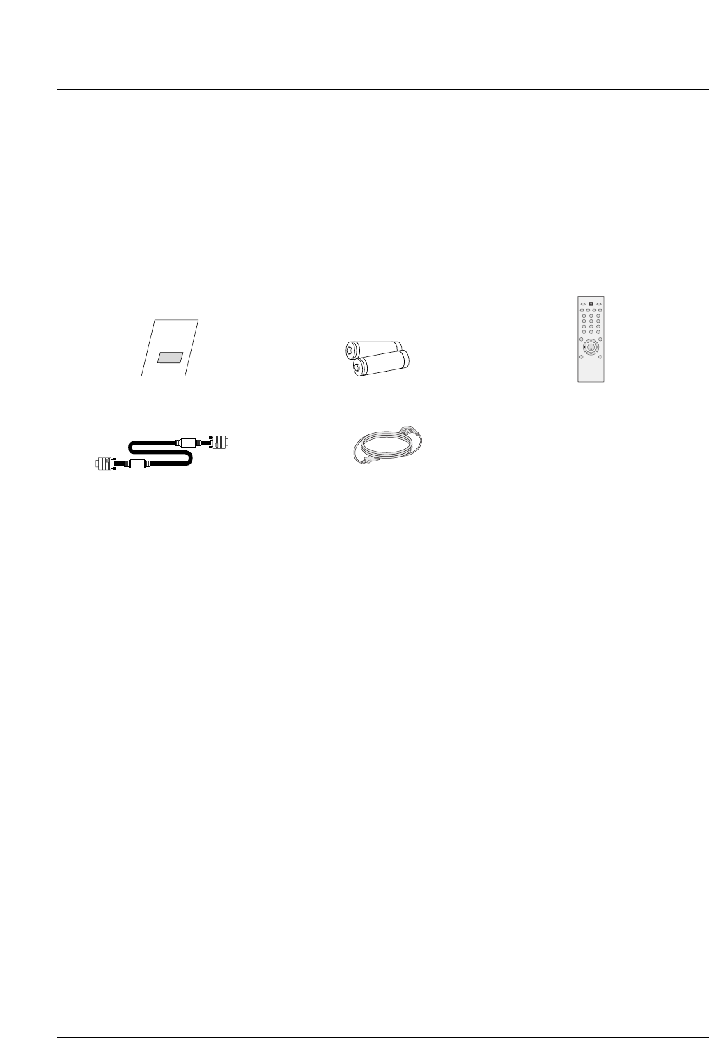
Ensure that the following accessories are included with your plasma display. If an accessory is missing, please contact the dealer
where you purchased the product.
Owner’s Manual
1.5V
1.5V
Batteries
Power Cord
123
456
78
0
**
*
9
SET
POWER
SLEEP
AV
PSM ARC AUTO
INPUT
VOL VOL
MENU
MUTE
EXIT
Remote Control
D-sub 15 pin cable
Accessories
Accessories
8 Plasma Monitor
Introduction
Controls
Controls
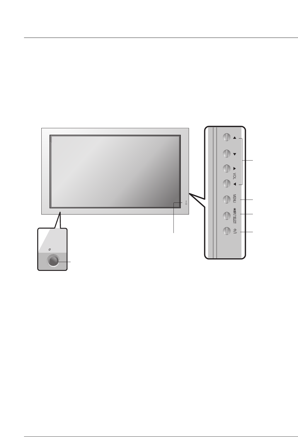
- This is a simplified representation of front panel.
- This picture shown below may be somewhat different from your monitor.
ON/OFF
1.Power Standby Indicator
Illuminates red in standby mode, Illuminates green when the
Set is turned on.
2. Remote Control Sensor
3. VOLUME (FF,GG) Buttons
EE, DDButtons
4. MENU Button
5. INPUT SELECT Button
6. Main Power Button
Switches the set on from standby or off to standby.
5
6
4
3
2
1
7
Owner’s Manual 9
Introduction
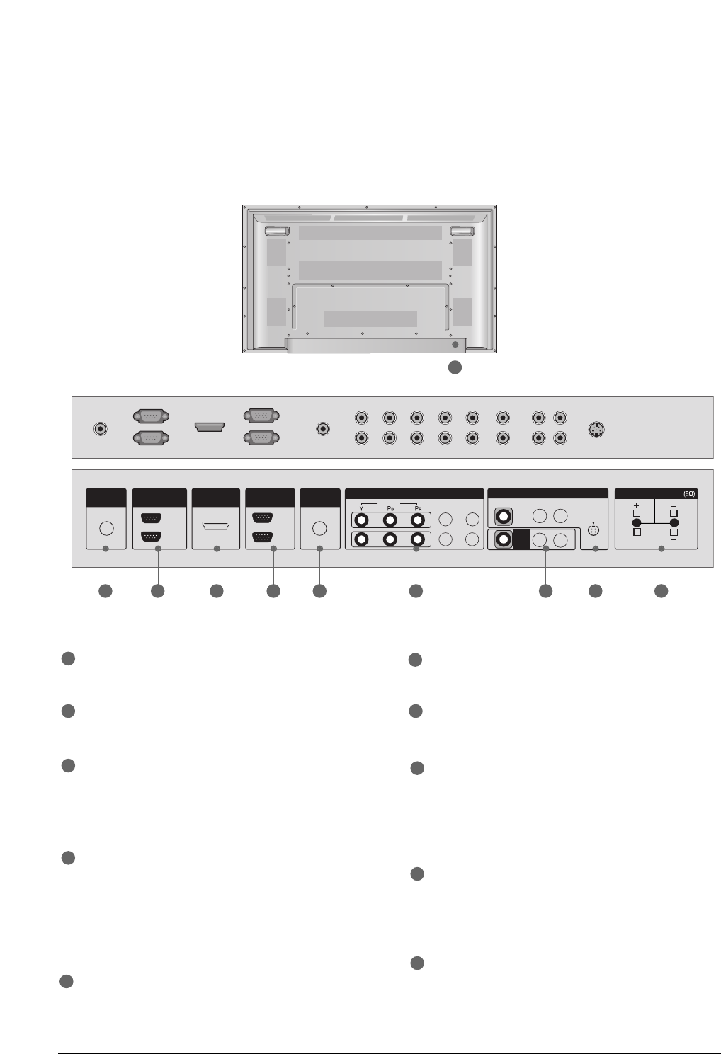
Connection Options
Connection Options
REMOTE CONTROL IN
Connect your wired remote control.
RS-232C IN (CONTROL & SERVICE) PORT
Connect to the RS-232C port on a PC.
HDMI/DVI IN
Connect a HDMI signal to 1(DVI) or 2.
Or DVI(VIDEO) signal to the 1(DVI) port with a DVI to
HDMI cable.
RGB INPUT
Connect the set output connector from a PC to the
appropriate input port.
RGB OUTPUT
You can watch the RGB signal on another set, connect
RGB OUTPUT to another set’s PC input port.
AUDIO (RGB/DVI)
Connect the monitor output from a PC to the appropriate
input port.
COMPONENT IN
Connect a component video/audio device to these jacks.
AV OUTPUT
Connect a second Set or monitor.
VIDEO IN
Connect audio/video output from an external device to
these jacks.
S-VIDEO
Connect S-Video out from an S-VIDEO device.
EXTERNAL SPEAKER (8 ohm output)
Connect to optional external speaker(s).
* For further information, refer to ‘Speaker & Speaker
Stand’manual.
POWER CORD SOCKET
This Monitor operates on an AC power. The voltage is
indicated on the Specifications page. Never attempt to
operate the Monitor on DC power.
1
7
2
3
4
5
6
8
9
10
- Connection panels shown may be somewhat different from your Monitor.
COMPONENT IN
OUT
IN
REMOTE
CONTROL IN
HDMI/DVI IN
RS-232C
(CONTROL&SERVICE)
IN
OUT
RGB
1
2
VIDEO
AUDIO
(RGB/DVI)
L-AUDIO-R
VIDEO
AV
OUT
AV IN
L-AUDIO-R
S-VIDEO
EXTERNAL SPEAKER
RL
1 2 3 4 6 7 8 95
10
10 Plasma Monitor
Introduction
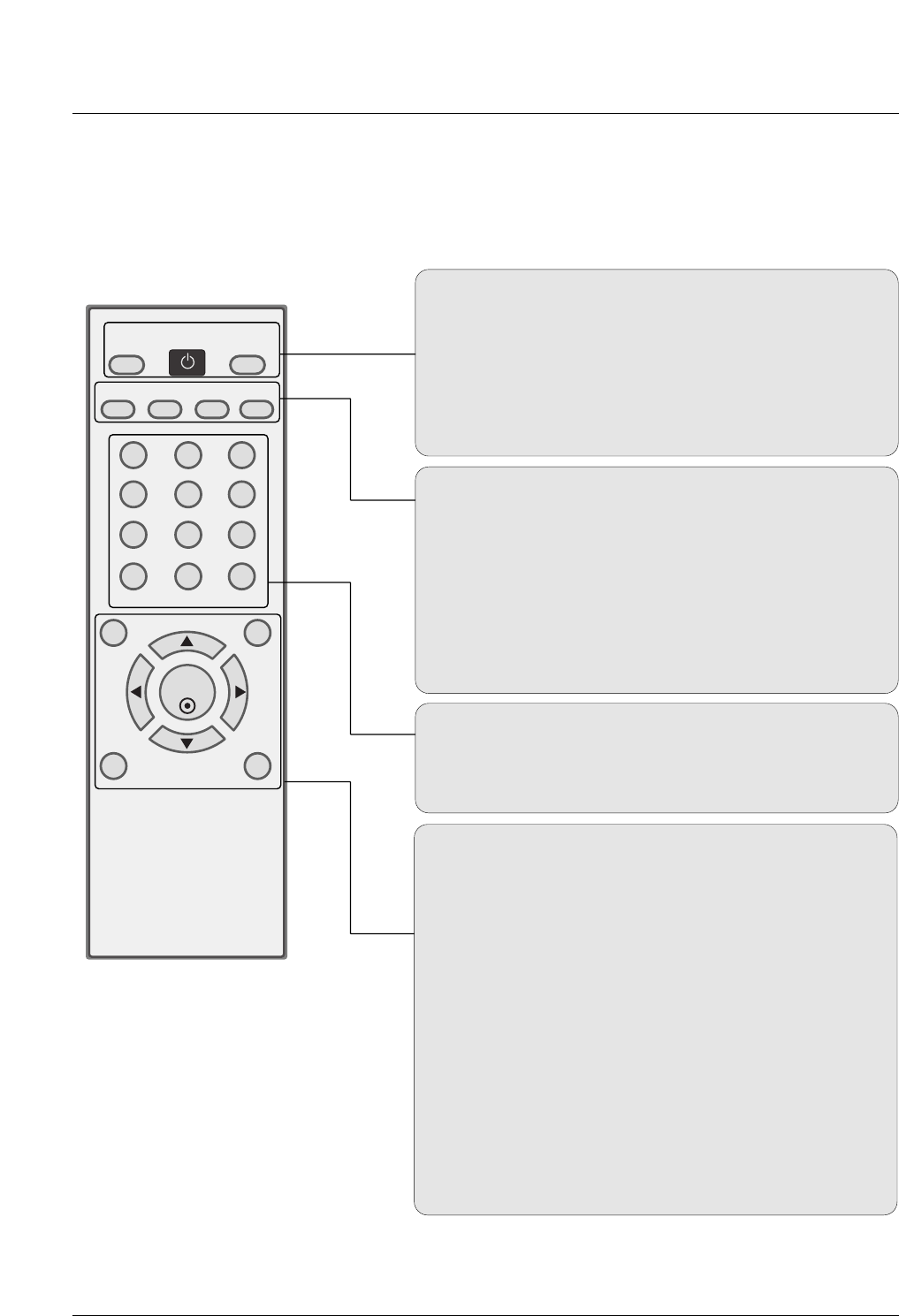
- When using the remote control, aim it at the remote control sensor on the monitor.
- Under certain conditions such as if the remote IR signal is interrupted, the remote control may not function. Press
the key again as necessary.
Remote Control Key Functions
Remote Control Key Functions
123
456
78
0
**
*
9
SET
POWER
SLEEP
AV
PSM ARC AUTO
INPUT
VOL VOL
MENU
MUTE
EXIT
AV
Selects: AV, Component 1-2, RGB, HDMI/DVI input sources.
POWER
Turns your monitor or any other programmed equipment on or
off, depending on mode.
INPUT
Selects: AV, Component 1-2, RGB, HDMI/DVI input sources.
AUTO
Automatic adjustment function
SLEEP
Sets the Sleep Timer.
PSM
Adjusts the factory preset picture according to the room.
ARC
Changes the picture format.
NUMBER buttons
Dosen’t work for monitor mode.
*
Not functional
MENU
Brings up the main menu to the screen.
EXIT
Clears all on-screen displays and returns to monitor viewing
from any menu.
VOLUME UP/DOWN
Increases/decreases the sound level.
THUMBSTICK (Up/Down/Left/Right/SET)
Navigate the on-screen menus and adjust the system set-
tings to your preference.
MUTE
Switches the sound on or off.
*
Not functional
Installing Batteries
• Open the battery compartment cover on the
back side and install the batteries matching
correct polarity (+ with +, - with -).
• Install two 1.5V AA batteries. Don’t mix old
or used batteries with new ones.
Replace cover.
Owner’s Manual 11
Introduction
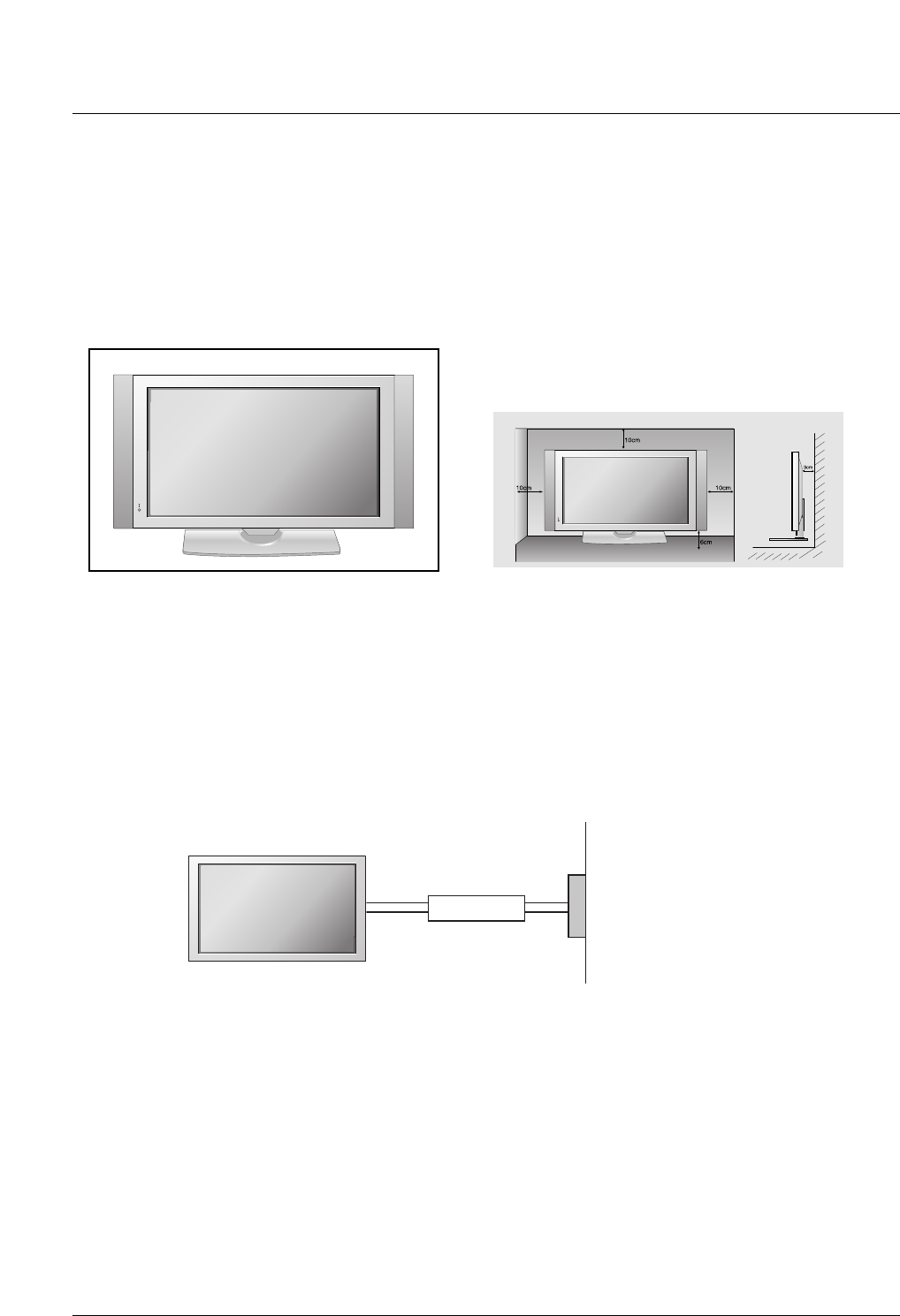
Desktop Pedestal Installation
Desktop Pedestal Installation
GROUNDING
Ensure that you connect the grounding / earth wire to prevent possible electric shock. If grounding
methods are not possible, have a qualified electrician install a separate circuit breaker. Do not try
to ground the unit by connecting it to telephone wires, lightening rods, or gas pipes.
Power Supply
Short-circuit Breaker
For proper ventilation, allow a clearance of 4inches on each side from the wall.
Installation
Installation
•This picture shown below may be somewhat different from your monitor.
12 Plasma Monitor
Installation
External Equipment Connections
External Equipment Connections
NOTE: Not all cables shown are included with the plasma display.
VCR Setup
VCR Setup
L R
S-VIDEO VIDEO
OUTPUT
SWITCH
ANT IN
ANT OUT
NENT IN
1
2
L-AUDIO-R
VIDEO
AV
OUT
AV IN
L-AUDIO-R
S-VIDEO
EXTERNAL SPEAK
R
ENT IN
1
2
L-AUDIO-R
VIDEO
AV
OUT
AV IN
L-AUDIO-R
S-VIDEO
EXTERNAL SPEAKER
RL
L R S-VIDEOVIDEO
OUTPUT
SWITCH
ANT IN
ANT OUT
VCR
VCR
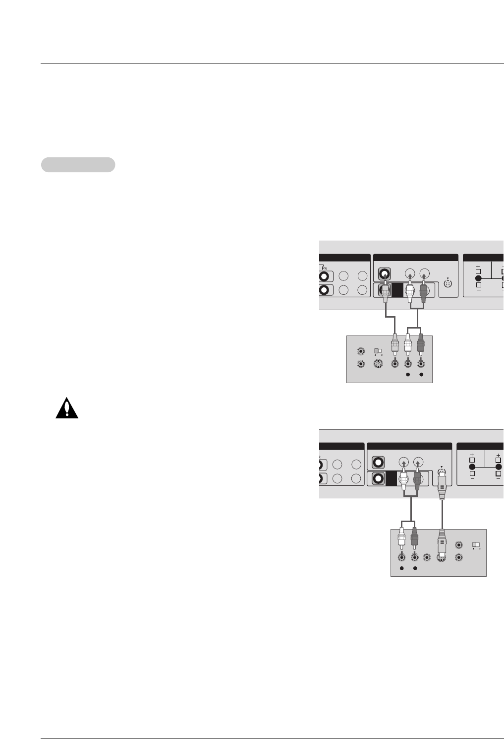
- To avoid picture noise (interference), leave an adequate distance between the VCR and monitor.
- Use the ISM Method (on the Special menu) feature to avoid having a fixed image remain on the screen for a long period of
time. Typically a frozen still picture from a VCR. If the 4:3 picture format is used; the fixed images on the sides of the screen
may remain visible on the screen.
Connection Option
1. Connect the audio and video cables from the VCR's output
jacks to the set input jacks, as shown in the figure.
When connecting the set to VCR, match the jack colors
(Video = yellow, Audio Left = white, and Audio Right = red).
If you connect an S-VIDEO output from VCR to the S-VIDEO
input, the picture quality is improved; compared to connect-
ing a regular VCR to the Video input.
2. Insert a video tape into the VCR and press PLAY on the
VCR. (Refer to the VCR owner’s manual.)
3. Select the input source with using the INPUT button on the
remote control.
Do not connect to both Video and S-
Video at the same time. In the event
that you connect both Video and the
S-Video cables, only the S-Video will
work.
Owner’s Manual 13
Installation
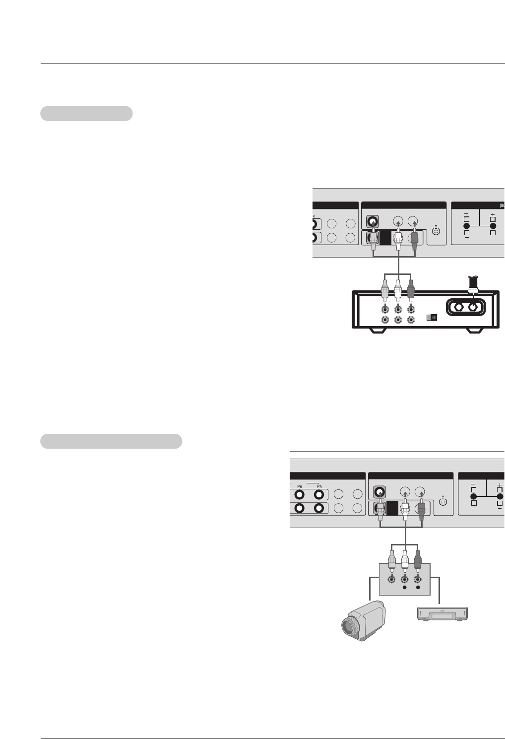
- After subscribing to a cable monitor service from a local provider and installing a converter, you can watch cable TV program-
ming. The monitor cannot display monitor programming unless a TV tuner device or cable TV converter box is connected to the
Monitor.
- For further information regarding cable monitor service, contact your local cable TV service provider(s).
How to connect
1. Connect the audio and video cables from the Cable Box's output
jacks to the monitor input jacks, as shown in the figure.
When connecting the monitor to a Cable Box, match the jack colors
(Video = yellow, Audio Left = white, and Audio Right = red).
Or, connect the Euro scart socket of the Cable box to the Euro scart
socket of the set.
How to use
1. Use the INPUT button on the remote control to select AV.
2. Select your desired channel with the remote control for cable box.
Cable
Cable TV Setup
TV Setup
ENT IN
1
2
L-AUDIO-R
VIDEO
AV
OUT
AV IN
L-AUDIO-R
S-VIDEO
EXTERNAL SPEAKER
RL
TV
VCR RF Cable
(R) AUDIO (L) VIDEO
34
OUTPUT
SWITCH
Cable Box
How to connect
1. Connect the audio and video cables from the external
equipment's output jacks to the monitor input jacks, as
shown in the figure.
When connecting the monitor to external equipment, match
the jack colors (Video = yellow, Audio Left = white, and
Audio Right = red).
Or, connect the Euro scart socket of the External A/V to the
Euro scart socket of the set.
How to use
1. Use the INPUT button on the remote control to select AV.
2. Operate the corresponding external equipment. Refer to
external equipment operating guide.
External
External A/V Source Setup
A/V Source Setup
COMPONENT IN
1
2
VIDEO
L-AUDIO-R
VIDEO
AV
OUT
AV IN
L-AUDIO-R
S-VIDEO
EXTERNAL SPEAKER
RL
L R
VIDEO
14 Plasma Monitor
Installation
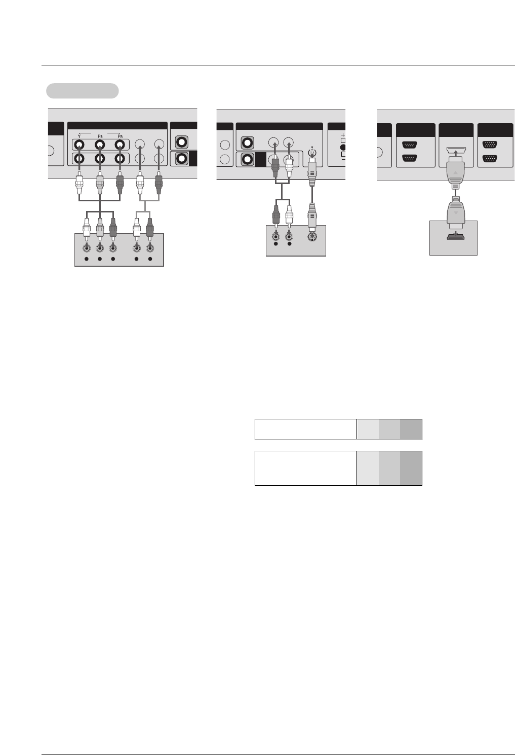
•Component Input ports
To get better picture quality, connect a DVD
player to the component input ports as shown.
Component ports of the
Monitor YPBPR
Video output ports
of DVD player
Y
Y
Y
Y
Pb
B-Y
Cb
PB
Pr
R-Y
Cr
PR
How to connect
1. Connect the DVD video outputs to the COMPONENT (Y, PB, PR) or HDMI IN 1(DVI) jacks and connect the DVD audio outputs
to the AUDIO INPUT jacks on the monitor, as shown in the figure.
2. If your DVD only has an S-Video output jack, connect this to the S-VIDEO input on the monitor and connect the DVD audio out-
puts to the AUDIO INPUT jacks on the monitor, as shown in the figure.
How to use
1. Turn on the DVD player, insert a DVD.
2. Use the INPUT button on the remote control to select Component 1, Component 2, or HDMI/DVI. (If connected to S-VIDEO,
select the AV external input source.)
3. Refer to the DVD player's manual for operating instructions.
DVD Setup
DVD Setup
DVD
COMPONENT IN
1
2
VIDEO
UDIO
B/DVI)
VIDEO
AV
OU
L-AUDIO-R
Y L RPBPR
L-AUDIO-R
VIDEO
AV
OUT
AV IN
DIO-R
S-VIDEO
EXTER
R
L R S-VIDEO
AUDIO
OUT
IN
MOTE
ROL IN
HDMI/DVI IN
RS-232C
(CONTROL&SERVICE)
IN
OUT
RGB
HDMI-DVD OUTPUT
Owner’s Manual 15
Installation
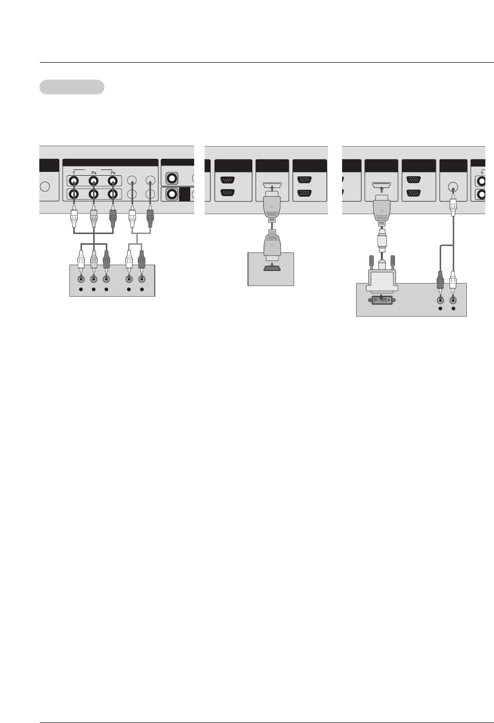
How to connect
1. Use the monitor’s COMPONENT (Y, PB, PR) INPUT, RGB or HDMI IN 1(DVI) to HDMI jack for video connec-
tions, depending on your set-top box connector. Then, make the corresponding audio connections.
How to use
1. Turn on the digital set-top box. (Refer to the owner’s manual for the digital set-top box.)
2. Use INPUT on the remote control to select Component 1, Component 2, RGB, or HDMI/DVI.
DTV Setup
DTV Setup
COMPONENT IN
1
2
VIDEO
AUDIO
GB/DVI)
VIDEO
AV
OUT
L-AUDIO-R
Y L RPBPR
OUT
IN
E
IN
HDMI/DVI IN
RS-232C
(CONTROL&SERVICE)
IN
OUT
RGB
HDMI-DTV OUTPUT
OUT
IN
HDMI/DVI IN
232C
L&SERVICE)
IN
OUT
RGB AUDIO
(RGB/DVI)
L R
DVI-DTV OUTPUT
Digital Set-top Box
- To watch digitally broadcast programs, purchase and connect a digital set-top box.
- This monitor supports HDCP (High-bandwidth Digital Contents Protection) protocol for
HDMI/DVI-DTV (480p,720p,1080i, 1080p) mode.
16 Plasma Monitor
Installation
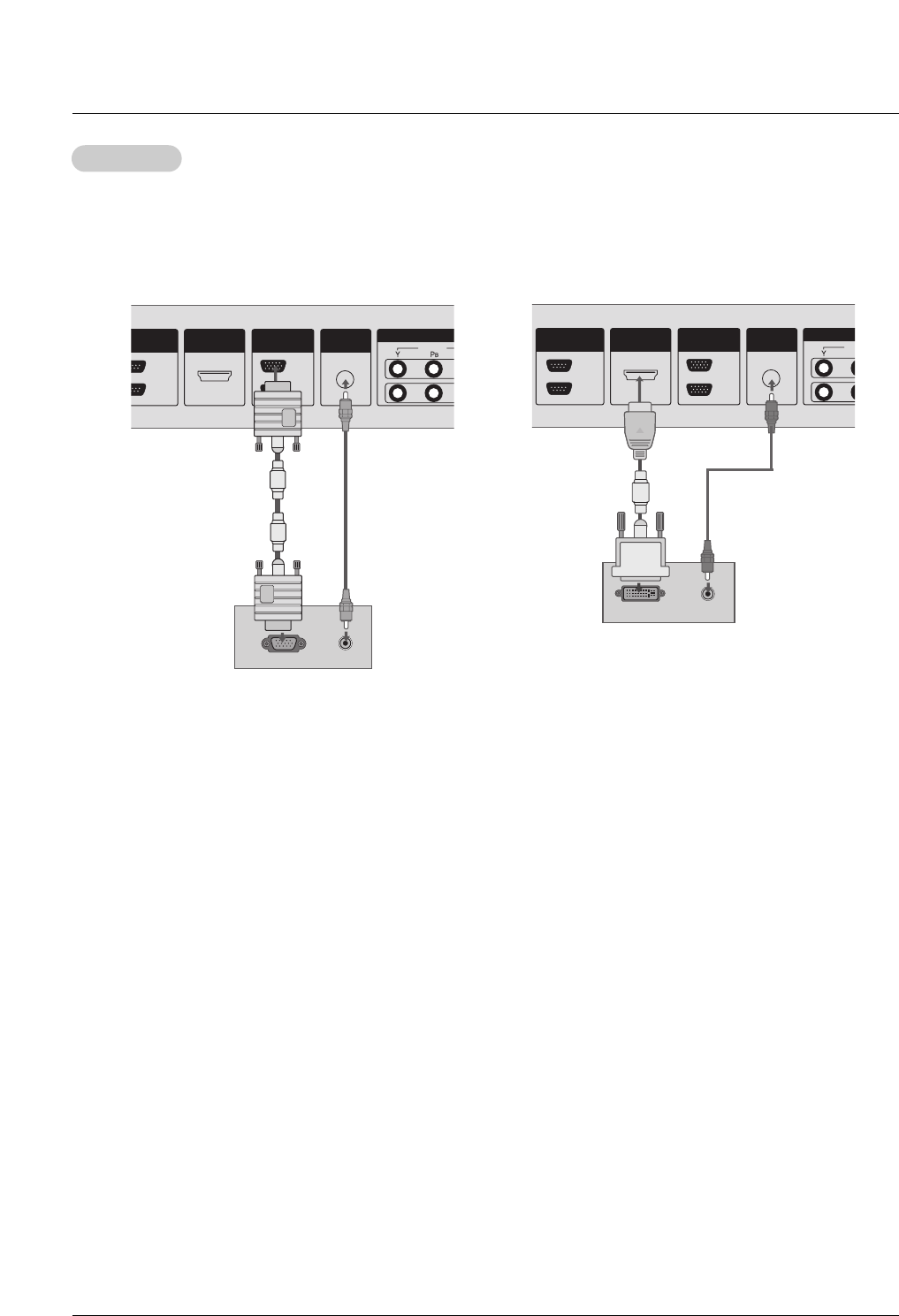
How to connect
1. To get the best picture quality, adjust the PC graphics card to a 1600x1200, 60Hz.
2. Use the monitor’s RGB INPUT or HDMI IN 1(DVI) port for video connections, depending on your PC connector.
If the graphic card on the PC does not output analog and digital RGB simultaneously, connect only one of either RGB IN or
HDMI IN 1(DVI) to display the PC on the monitor.
If the graphic card on the PC does output analog and digital RGB simultaneously, set the monitor to either RGB or HDMI1/DVI;
(the other mode is set to Plug and Play automatically by the monitor.)
3. Then, make the corresponding audio connections. If using a sound card, adjust the PC sound as required.
How to use
1. Turn on the PC and the monitor.
2. Turn on the display by pressing the POWER button on the monitor's remote control.
3. Use the INPUT button on the remote control to select RGB or HDMI/DVI.
4. Check the image on your monitor. There may be noise associated with the resolution, vertical pattern, contrast or brightness in
PC mode. If noise is present, change the PC mode to another resolution, change the refresh rate to another rate or adjust the
brightness and contrast on the menu until the picture is clear. If the refresh rate of the PC graphic card can not be changed,
change the PC graphic card or consult the manufacturer of the PC graphic card.
NOTES: • Avoid keeping a fixed image on the monitor's screen for a long period of time. The fixed image may become perma-
nently imprinted on the screen. Use the Orbiter screen saver when possible.
• The synchronization input form for Horizontal and Vertical frequencies is separate.
PC Setup
PC Setup
COMPO
OUT
IN
HDMI/DVI IN
RS-232C
ROL&SERVICE)
IN
OUT
RGB
VIDEO
AUDIO
(RGB/DVI)
RGB OUTPUT AUDIO
C
OUT
IN
HDMI/DVI IN
RS-232C
(CONTROL&SERVICE)
IN
OUT
RGB
VID
AUDIO
(RGB/DVI)
DVI-PC OUTPUT AUDIO
- This monitor provides Plug and Play capability, meaning that the PC adjusts automatically to its settings. The monitor sends
configuration information (EDID) to the PC using the Video Electronics Standard Association (VESA) Display Data Channel
(DDC) protocol.
- The monitor perceives 640x480, 60Hz as DTV 480p based on the PC graphic card. In this case, change the screen scanning
rate for the graphic card.
Owner’s Manual 17
Installation
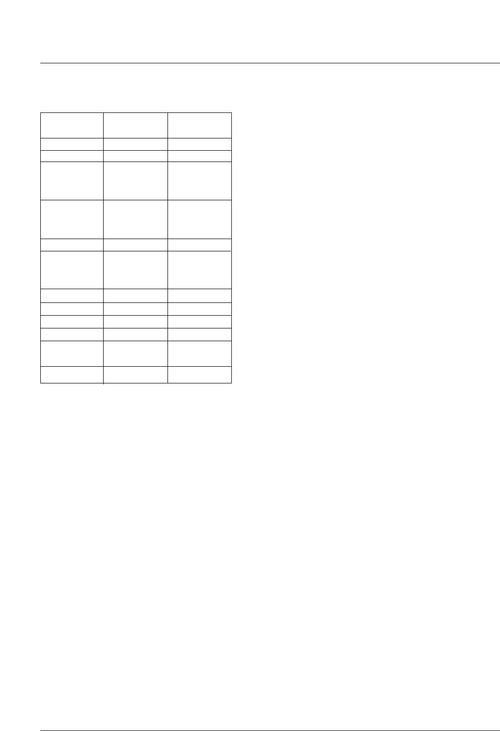
Monitor Display Specifications (RGB-PC / HDMI/DVI-PC Mode)
Resolution
640x480
720x400
640x480
800x600
Horizontal
Frequency(KHz)
31.469
31.468
31.469
37.500
43.269
37.879
46.875
53.674
49.725
48.363
60.023
68.68
44.442
47.00
47.72
47.00
63.981
79.98
75.00
70.08
70.08
59.94
75.00
85.00
60.31
75.00
85.06
74.55
60.00
75.02
85.00
60.00
60.00
60.00
60.00
60.00
75.00
60.00
Vertical
Frequency(Hz)
832x624
1024x768
1600x1200
1280x720
1280x1024
1280x768
1360x768
1366x768

18 Plasma Monitor
Operation
Operation
Operation
Menu Language Selection
Menu Language Selection
T
Turning on the Monitor
urning on the Monitor
Turning on the Monitor just after installation
1. Connect power cord correctly. At this moment, the Monitor is switched to standby mode.
2. Press the INPUT or button on the Monitor or press the POWER, INPUT button on the remote
control and then the Monitor will switch on.
-The menus can be shown on the screen in the selected language. First select your language.
1. Press the MENU button and then use DD/ EEbutton to select the SPECIAL menu.
2. Press the GGbutton and then use DD/ EEbutton to select Language.
3. Press the GGbutton and then use DD/ EEbutton to select your desired language.
From this point on, the on-screen menus will be shown in the language of your choice.
4. Press the ENTER button to save.
• Press the MENU button to return to the previous menu.
Owner’s Manual 19
Operation
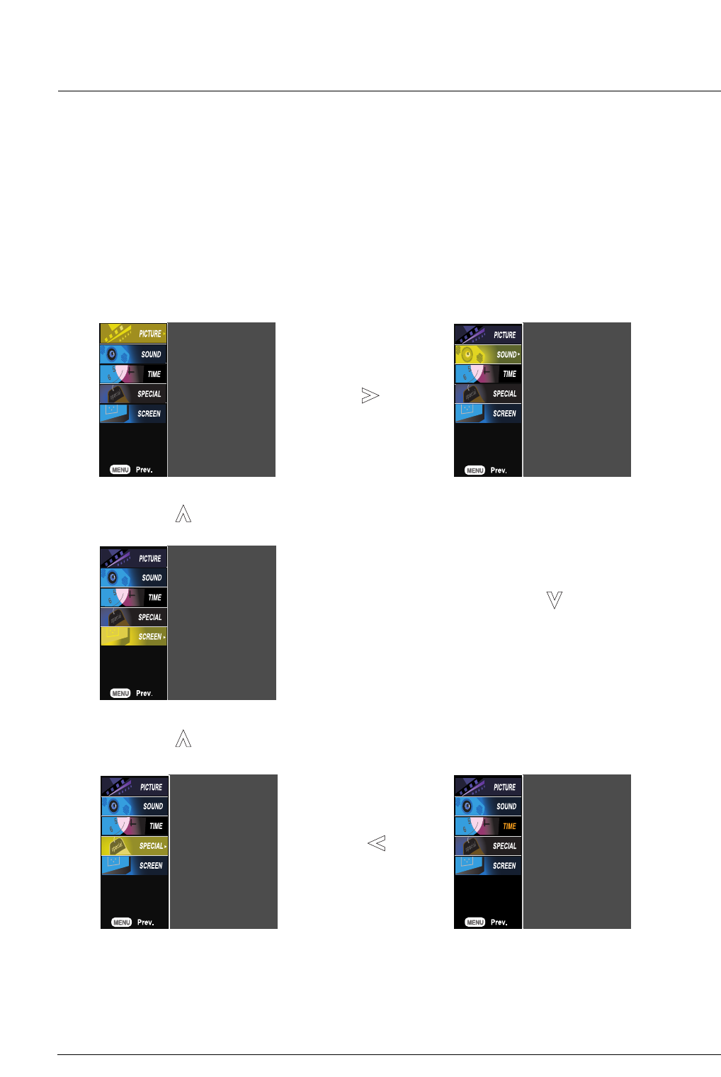
On Screen Menus Selection
On Screen Menus Selection
1. Press the MENU button and then use DD/ EEbutton to select the each menu.
2. Press the GGbutton and then use DD/ EE/ FF / GGbutton to display the available menus.
PSM
CSM
XD
Advanced
Reset
SSM
AVL
Balance
Speaker
Clock
Off time
On time
Auto sleep
Language
Child lock
ISM Method
Set ID
Tile mode
Logo light
XD Demo
Auto config.
Manual config.
XGA Mode
ARC
Reset
Your TV's OSD (On Screen Display) may differ slightly from what is shown in this manual.
20 Plasma Monitor
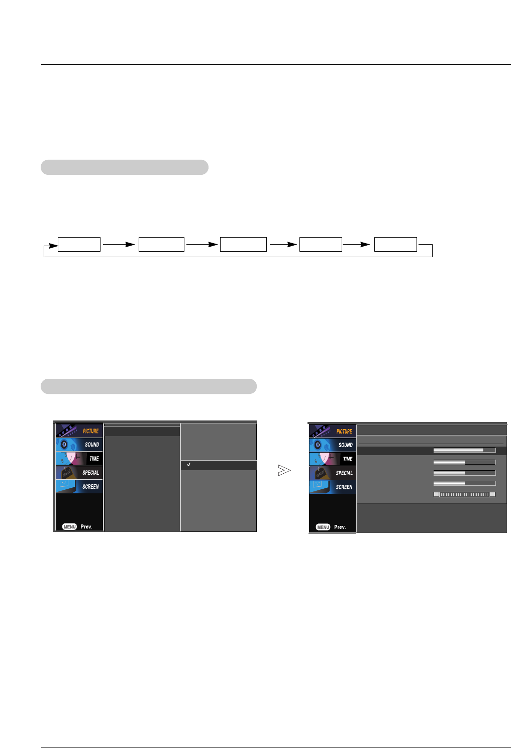
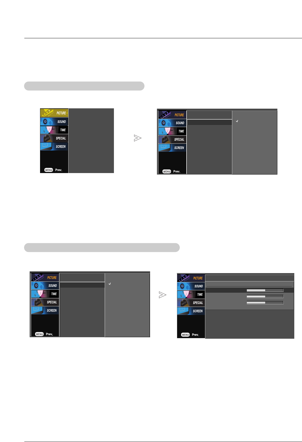
1. Press the PSM button repeatedly to select the picture appearance setup option as shown below.
Picture Status Memory (PSM)
Picture Status Memory (PSM)
- PSM adjusts the Monitor for the best picture appearance.
- When adjusting Picture menu options (contrast, brightness, color, sharpness, and tint) manually, PSM automatically changes to
User.
•You can also select Dynamic,Standard,Mild,User 1 or User 2 in the PICTURE menu.
•Dynamic,Standard, and Mild settings are preset for optimum picture quality at the factory and cannot be changed.
Dynamic Standard Mild User 1 User2
- You can adjust picture contrast, brightness, colour, sharpness, and tint to the levels you prefer.
1. Press the MENU button and then use DD / EEbutton to select the PICTURE menu.
2. Press the GGbutton and then use DD / EEbutton to select the desired picture option (Contrast,Brightness,Color,Sharpness or
Tint).
3. Press the GGbutton and then use FF / GGbutton to make appropriate adjustments.
4. Press the ENTER button to save the new settings.
Manual Picture Control (PSM -
Manual Picture Control (PSM - User option)
option)
PSM
CSM
XD
Advanced
Reset
Dynamic
Standard
Mild
User1 G
User2
User1
Contrast 85 G
Brightness 50
Color 50
Sharpness 50
Tint 0 R G
Picture Menu Options
Picture Menu Options
Owner’s Manual 21
PSM
CSM
XD
Advanced
Reset
PSM
CSM G
XD
Advanced
Reset
Cool
Normal
Warm
User
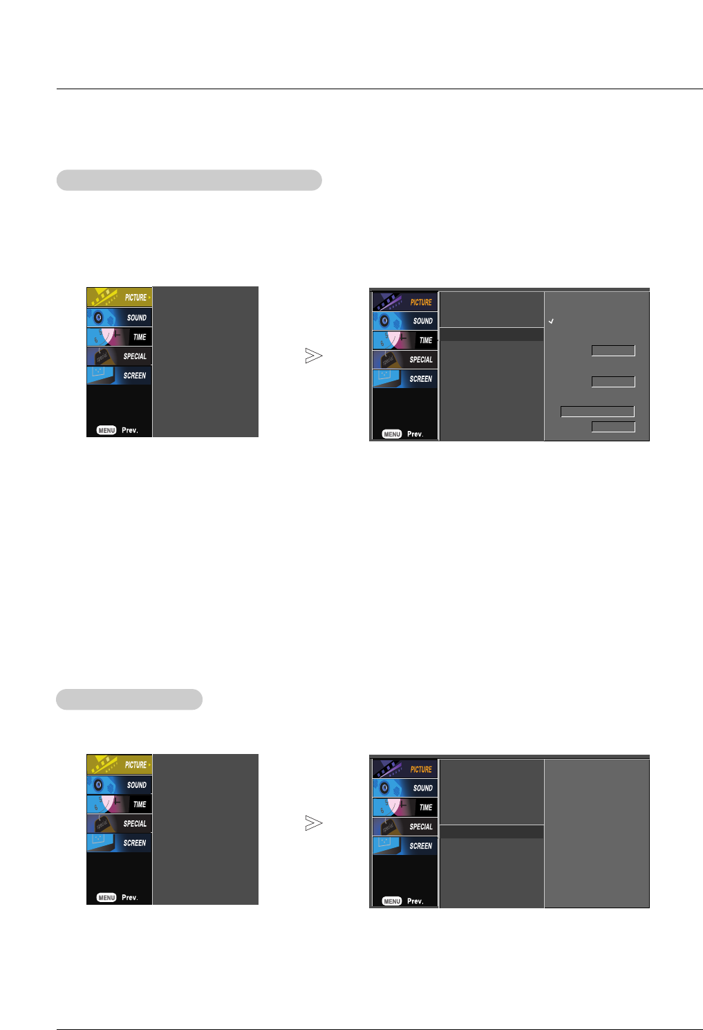
- To initialize values (reset to default settings), select the Cool option.
Color Status Memory (CSM)
Color Status Memory (CSM)
Manual Color
Manual Color T
Temperature control (CSM -
emperature control (CSM - User option)
option)
- You can adjust red, green, or blue to any color temperature you prefer.
1. Press the MENU button and then use DD / EEbutton to select the PICTURE menu.
2. Press the GGbutton and then use DD / EEbutton to select CSM.
3. Press the GGbutton and then use DD / EEbutton to select User.
4. Press the GGbutton and then use DD / EEbutton to select Red, Green or Blue.
5. Use the FF / GGbutton to make appropriate adjustments.
• The adjustment range of Red, Green and Blue is -10 ~ +10.
6. Press the ENTER button to save the new settings.
1. Press the MENU button and then use DD / EEbutton to select the PICTURE menu.
2. Press the GGbutton and then use DD / EEbutton to select CSM.
3. Press the GGbutton and then use DD / EEbutton to select either Cool, Normal, Warm, or User.
4. Press the ENTER button to save the new settings.
User
Red 0 G
Green 0
Blue 0
PSM
CSM G
XD
Advanced
Reset
Warm
Normal
Cool
User
22 Plasma Monitor
- XD is LG Electronic’s unique picture improving technology to display a real HD source through an advanced digital signal pro-
cessing algorithm.
- When selecting PSM options (Dynamic,Standard,Mild), XD is automatically changed to Auto.
- When selecting PSM options (User 1 or User 2), you can choose the Auto / Manual.
- When selecting the Manual, you can adjust the XD Contrast, XD color and XD Noise.
XD (Picture Improvement
XD (Picture Improvement T
Technology)
echnology)
PSM
CSM
XD G
Advanced
Reset
Auto
Manual
XD Contrast
On
XD Color
On
XD NR
Off
MPEG NR 0
PSM
CSM
XD
Advanced
Reset G
PSM
CSM
XD
Advanced
Reset
PSM
CSM
XD
Advanced
Reset
1. Press the MENU button and then use DD / EEbutton to select the PICTURE menu.
2. Press the GGbutton and then use DD/ EEbutton to select XD.
3. Press the GGbutton and then use DD / EEbutton to select either Auto or Manual.
Selecting the Manual
a. Press the GGbutton and then use FF / GGbutton to select XD Contrast, XD Color or XD Noise.
■XD Contrast: Optimizing the contrast automatically according to the brightness of the reflection.
■XD Color:Adjusting the colors of the reflection automatically to reproduce as closely as possible to the natural colors.
■XD NR: Removing the noise up to the point where it does not damage the original picture.
■MPEG NR: You can select it to reduce the picture noise which may appear on the screen while watching the AV.
b. Use the DD / EEbutton to select On or Off.
4. Press the ENTER button to save the new settings.
1. Press the MENU button and then use DD / EEbutton to select the PICTURE menu.
2. Press the GGbutton and then use DD / EEbutton to select Reset.
3. Press the GGbutton to reset the Picture menu options to original values.
To set
Picture Reset
Picture Reset
- Use to quickly reset all the Video menu options to their original factory preset values.
Owner’s Manual 23
Advanced - Cinema 3:2 Pull down Mode
Advanced - Cinema 3:2 Pull down Mode
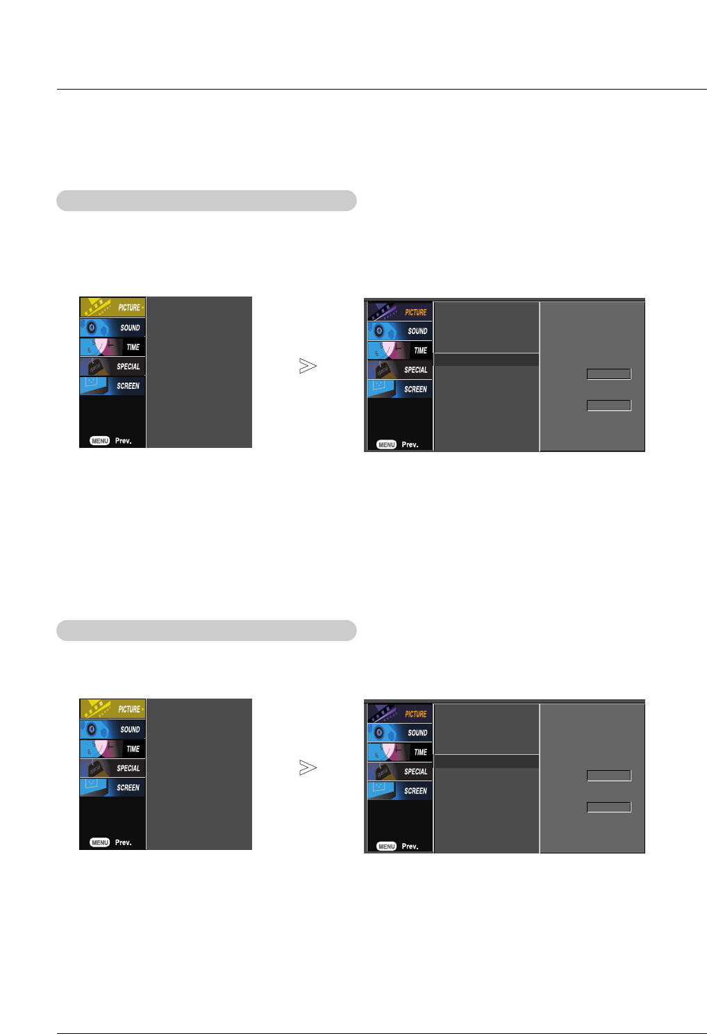
- Set up the TV for the best picture appearance for viewing movies.
- When you operate Cinema 3:2 Mode (3:2 Pull-Down Mode or Cinema Correction Mode), the TV will adjust 24 fps video from
movies to 30 fps video for display.
- This feature operates only in Analog, AV, and Component 480i mode.
1. Press the MENU button and then use DD / EEbutton to select the PICTURE menu.
2. Press the GGbutton and then use DD / EEbutton to select Advanced.
3. Press the GGbutton and then use DD / EEbutton to select Cinema.
4. Press the GGbutton and then use DD / EEbutton to select On or Off.
5. Press the ENTER button to save the new settings.
PSM
CSM
XD
Advanced G
Reset
Cinema
Off
Black level
Low
PSM
CSM
XD
Advanced
Reset
Advanced - Black (Darkness) Level
Advanced - Black (Darkness) Level
- Adjusting the contrast and the brightness of the screen using the black level of the screen.
- This feature operates only in AV or HDMI mode.
1. Press the MENU button and then use DD / EEbutton to select the PICTURE menu.
2. Press the GGbutton and then use DD / EEbutton to select Advanced.
3. Press the GGbutton and then use DD / EEbutton to select Black level.
4. Press the GGbutton and then use DD / EEbutton to select Low or High.
■Low: The screen gets darker.
■High: The screen gets brighter.
5. Press the ENTER button to save the new settings.
PSM
CSM
XD
Advanced G
Reset
Cinema
Off
Black level
Low
PSM
CSM
XD
Advanced
Reset
24 Plasma Monitor
Operation
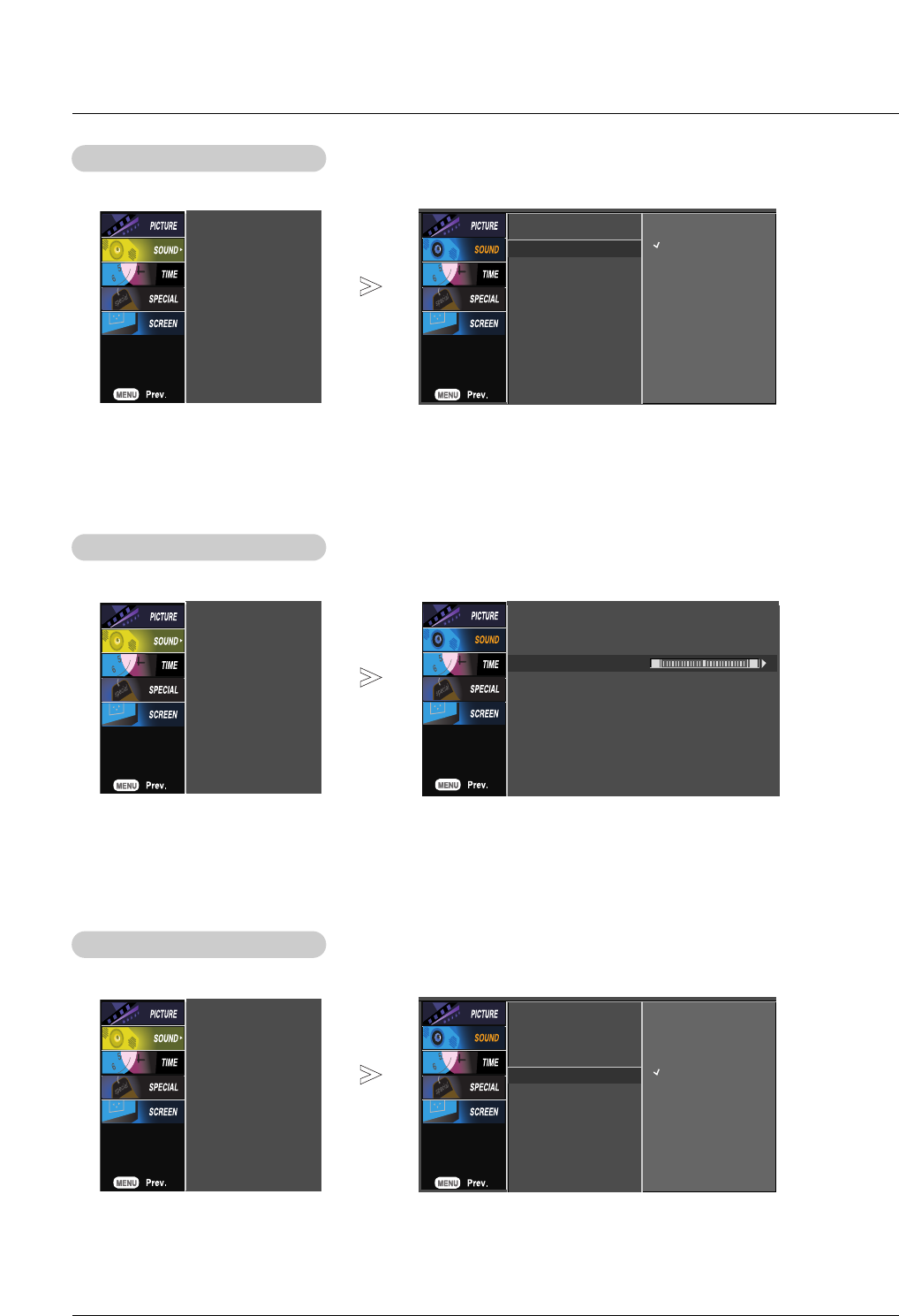
1. Press the MENU button and then use DD / EEbutton to select the SOUND menu.
2. Press the GGbutton and then use DD / EEbutton to select the desired sound option (Treble or Bass).
3. Press the GGbutton and then use FF / GGbutton to make appropriate adjustments.
4. Press the ENTER button to save the new settings.
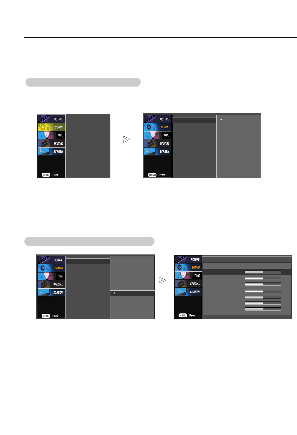
1. Press the MENU button and then use DD / EEbutton to select the SOUND menu.
2. Press the GGbutton and then use DD / EEbutton to select SSM.
3. Press the GGbutton and then use DD / EEbutton to select Surround MAX,Flat,Music,Movie,Sports,or User.
4. Press the ENTER button to save the new settings.
Manual Sound Control (SSM -
Manual Sound Control (SSM - User option)
option)
Sound Menu Options
Sound Menu Options
Sound Status Memory (SSM)
Sound Status Memory (SSM)
- SSM lets you enjoy the best sound without any special adjustment because the Monitor has the appropriate
sound options based on the program content.
- When adjusting sound options (treble, bass) manually, DASP automatically changes to Off.
SSM
AVL
Balance
Speaker
SSM G
AVL
Balance
Speaker
Surround MAX
Flat
Music
Movie
Sports
User
SSM
AVL
Balance
Speaker
Surround MAX
Flat
Music
Movie
Sports
User G
User
120Hz FFG
200Hz
500Hz
1.2KHz
3KHz
7.5KHz
12KHz
Owner’s Manual 25
Operation
- This feature maintains an equal volume level; even if you change channels.
1. Press the MENU button and then use DD / EEbutton to select the SOUND menu.
2. Press the GGbutton and then use DD / EEbutton to select AV L .
3. Press the GGbutton and then use DD / EEbutton to select On or Off.
4. Press the ENTER button to save the new settings.
1. Press the MENU button and then use DD / EEbutton to select the SOUND menu.
2. Press the GGbutton and then use DD / EEbutton to select Balance.
3. Press the GGbutton and then use FF / GGbutton to make appropriate adjustments.
4. Press the ENTER button to save the new settings.
A
AVL
VL (Auto V
(Auto Volume Leveler)
olume Leveler)
- Adjust the left/right sound of speaker to suit your taste and room situations.
Balance
Balance
SSM
AVL
Balance
Speaker
SSM
AVL G
Balance
Speaker
On
Off
- Turn the TV speakers off if using external audio equipment.
1. Press the MENU button and then use DD / EEbutton to select the SOUND menu.
2. Press the GGbutton and then use DD / EEbutton to select Speaker.
3. Press the GGbutton and then use DD / EEbutton to select On or Off.
4. Press the ENTER button to save the new settings.
TV Speakers On/Of
TV Speakers On/Off Setup
f Setup
SSM
AVL
Balance
Speaker
SSM
AVL
Balance
Speaker GOn
Off
SSM
AVL
Balance
Speaker
SSM
AVL
Balance 0
TV Speaker
L R
26 Plasma Monitor
Operation
- Timer function operates only if current time has already been set.
- Off-Timer function overrides On-Timer function if they are set to the same time.
- If you do not press any button within 2 hours after the monitor turns on with the On Timer function, the monitor will
automatically revert to standby mode.
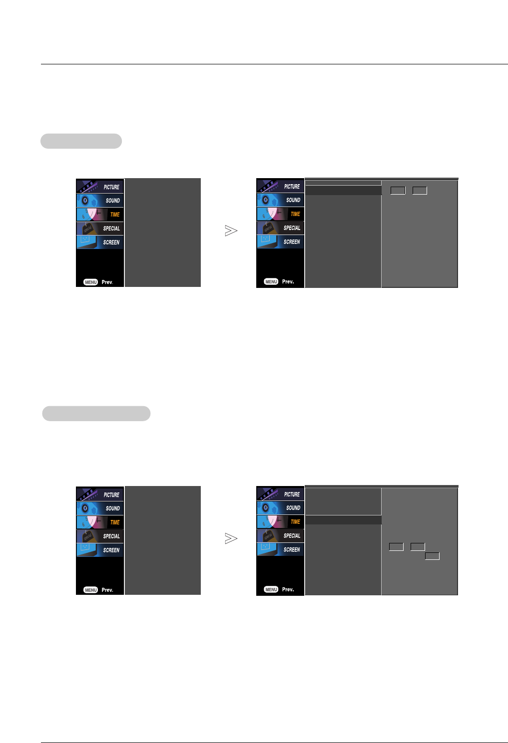
On/Of
On/Off
f T
Timer Setup
imer Setup
1. Press the MENU button and then use DD / EEbutton to select the TIME menu.
2. Press the GGbutton and then use DD / EEbutton to select Off time or On time.
3. Press the GGbutton and then use DD / EEbutton to select On.
• To cancel On/Off timer function, select Off.
4. Press the GGbutton and then use DD / EEbutton to set the hour.
5. Press the GGbutton and then use DD / EEbutton to set the minutes.
For only On timer function; Press the GGbutton and then use DD / EEbutton to set volume level.
6. Press the ENTER button to save the new settings.
Clock Setup
Clock Setup
- If current time setting is wrong, correct the clock setting.
1. Press the MENU button and then use DD / EEbutton to select the TIME menu.
2. Press the GGbutton and then use DD / EEbutton to select Clock.
3. Press the GGbutton and then use DD / EEbutton to set the hour.
4. Press the GGbutton and then use DD / EEbutton to set the minutes.
5. Press the ENTER button to save the new settings.
T
Timer Menu Options
imer Menu Options
Clock
Off time
On time
Auto sleep
Clock G
Off time
On time
Auto sleep
- - : - - - -
Clock
Off time
On time
Auto sleep
Clock
Off time
On time G
Auto sleep
On
Off
6 : 30 AM
Volume 17
Owner’s Manual 27
Operation
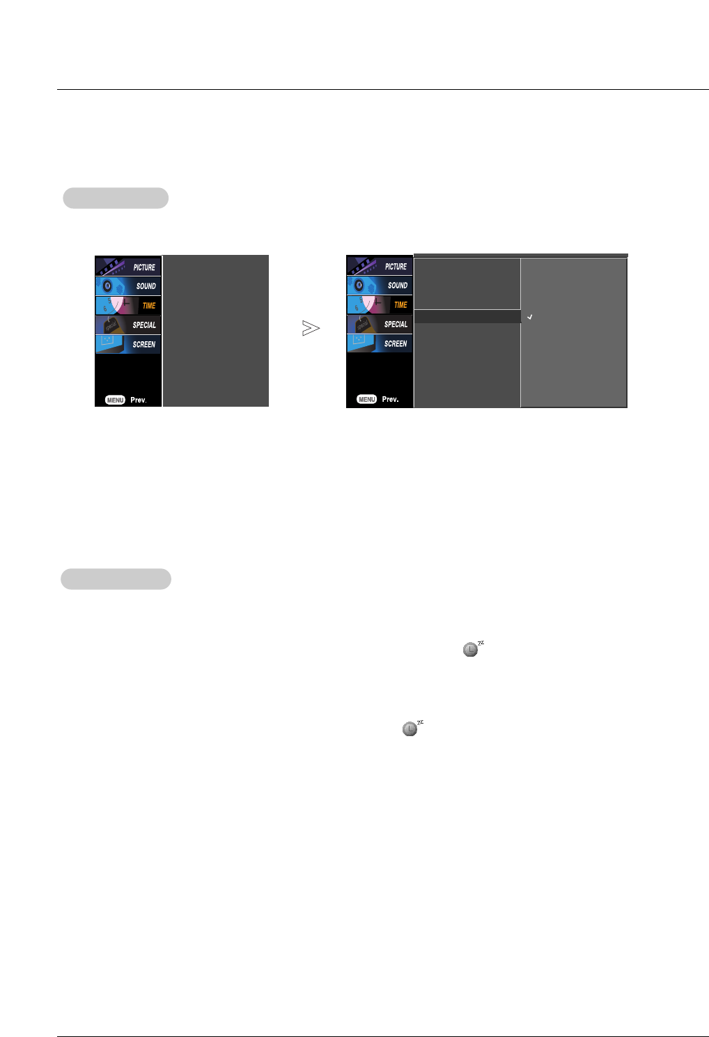
Auto Sleep
Auto Sleep
- If there is no input signal, the Monitor turns off automatically after 10 minutes.
1. Press the MENU button and then use DD / EEbutton to select the TIME menu.
2. Press the GGbutton and then use DD / EEbutton to select Auto sleep.
3. Press the GGbutton and then use DD / EEbutton to select On or Off.
4. Press the ENTER button to save the new settings.
Sleep
Sleep T
Timer
imer
- The sleep timer turns the Monitor off at a preset time. Note that this setting is cleared when the monitor is turned off.
1. Press the SLEEP button repeatedly to select the number of minutes. First the --- Min option appears on the
screen, followed by the following sleep timer options: 10, 20, 30, 60, 90, 120, 180, and 240 minutes.
2. When the number of minutes you want is displayed on the screen, press the ENTER button. The timer begins to
count down from the number of minutes selected.
3. To check the remaining minutes before the monitor turns off, press the SLEEP or ENTER button once.
4. To cancel the Sleep Timer, press the SLEEP button repeatedly until --- Min appears.
Clock
Off time
On time
Auto sleep
Clock
Off time
On time
Auto sleep GOn
Off
28 Plasma Monitor
Operation
Special Menu Options
Special Menu Options
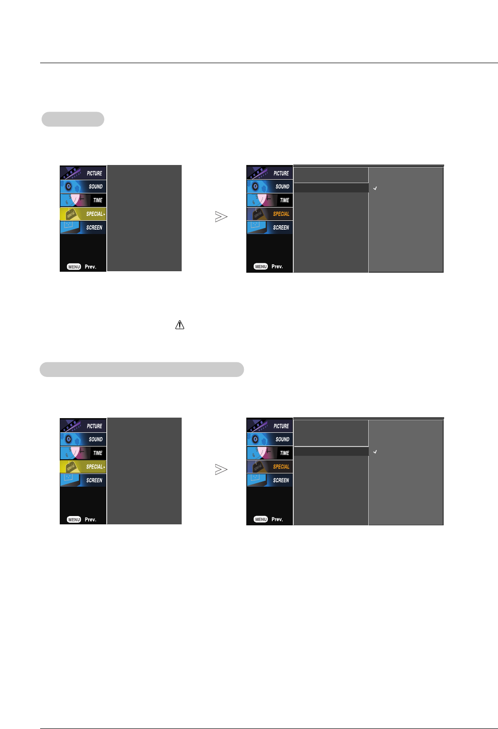
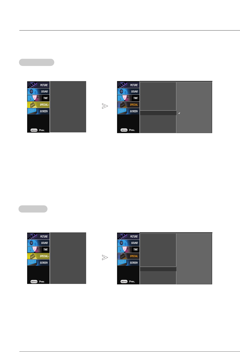
Child Lock
Child Lock
- The monitor can be set up so that it can only be used with the remote control.
- This feature can be used to prevent unauthorized viewing by disabling the front panel controls.
- This Monitor is programmed to remember which option it was last set to even if you turn the monitor off.
1. Press the MENU button and then use DD / EEbutton to select the SPECIAL menu.
2. Press the GGbutton and then use DD / EEbutton to select Child lock.
3. Press the GGbutton and then use DD / EEbutton to select On or Off.
• When you select On, the display ‘ Key lock’appears on the screen if any button on the front panel is pressed.
4. Press the ENTER button to save the new settings.
W
- A frozen still picture from a PC/video game displayed on the screen for prolonged periods will result in an ghost
image remaining; even when you change the image. Avoid allowing a fixed or still image to remain on the Monitor's
screen for a long period of time.
1. Press the MENU button and then use DD / EEbutton to select the SPECIAL menu.
2. Press the GGbutton and then use DD / EEbutton to select ISM Method.
3. Press the GGbutton and then use DD / EEbutton to select either Normal, White wash, Orbiter, or Inversion.
• Normal
If image sticking is never a problem, ISM is not necessary - set this to Normal.
• White wash
White Wash removes permanent images from the screen. Note: An excessive permanent image may be impossible to clear
completely using White Wash. To return to normal viewing, press the any button.
• Orbiter
Orbiter may help prevent ghost images. However, it is best not to allow any fixed image to remain on the screen. To avoid a
permanent image on the screen, the image will move every 2 minutes.
• Inversion
Inversion will automatically invert the Plasma Monitor color every 30 minutes.
• Orb. + Inv.
This function Inverts the panel color of the screen and may help prevent ghost image. The panel color is automatically inverted
every 30 minutes and the screen will move every 2 minutes.
4. Press the ENTER button to save the new settings.
Image Sticking Minimization (ISM) Method
Image Sticking Minimization (ISM) Method
Language
Child lock
ISM Method
Set ID
Tile mode
Low power
XD Demo
Language
Child lock G
ISM Method
Set ID
Tile mode
Low power
XD Demo
On
Off
Language
Child lock
ISM Method
Set ID
Tile mode
Low power
XD Demo
Language
Child lock
ISM Method G
Set ID
Tile mode
Low power
XD Demo
Normal
White Wash
Orbiter
Inversion
orb. + Inv.
Owner’s Manual 29
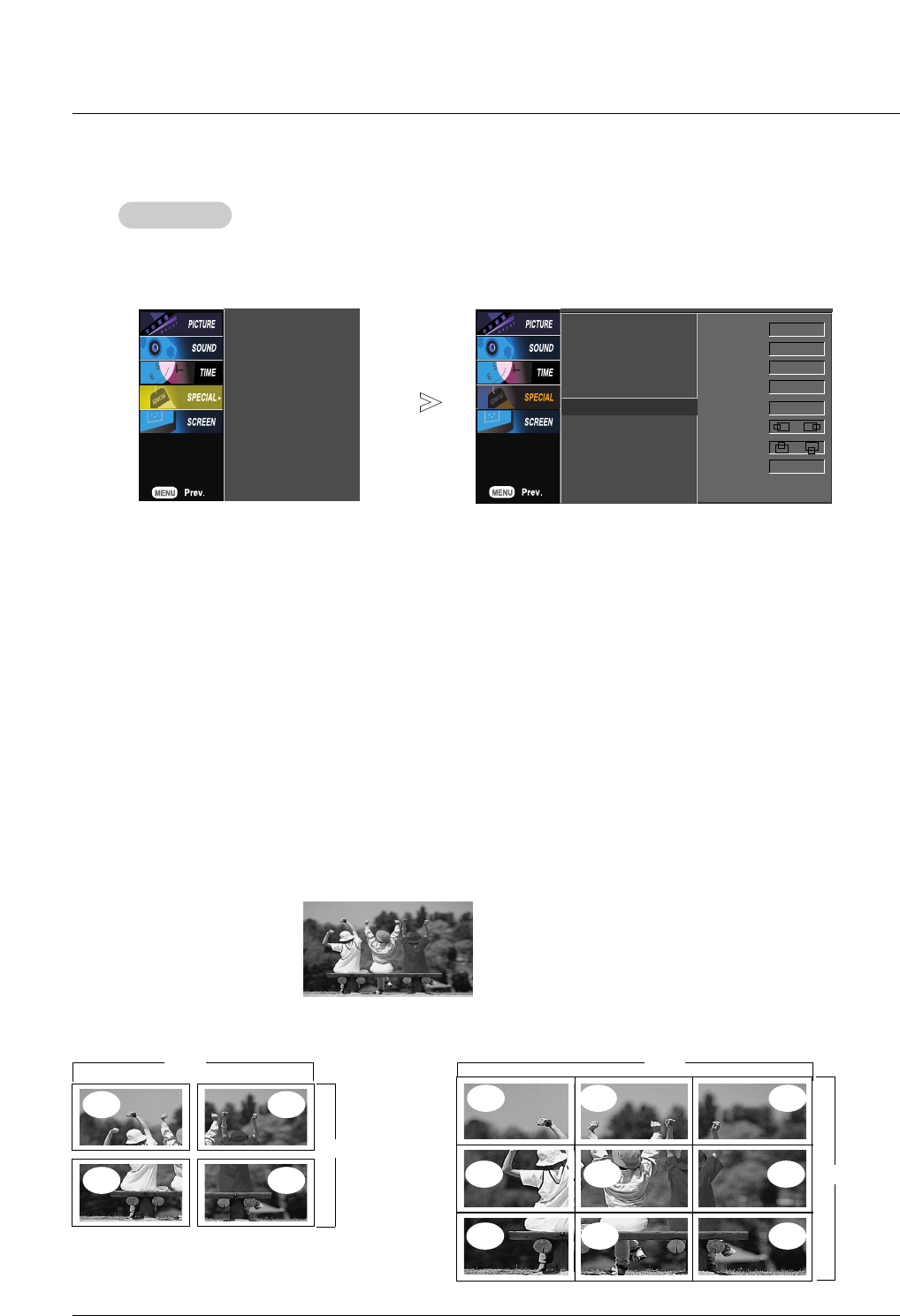
Operation
T
Tile Mode
ile Mode
- Must be displayed with various other products.
- Must be in a function that can be connected to RS-232C or RGB Out.
- It is used to enlarge the screen and also used with several products to view screen.
Tile mode and choose Tile alignment and set the ID of the current product to set location.
Only after pressing the SET button the adjustments made to the settings will be saved.
• Tile ID
Select the location of the Tile by setting an ID.
• H Size
Adjust the horizontal size of the screen taking into account the size of the bezel.
• V Size
Adjust the vertical size of the screen taking into account the size of the bezel.
• H-Position
Moving the screen position horizontally.
• V-Position
Moving the screen position vertically.
• Reset
Function to initialize and release Tile.
All Tile setting are released when selecting Tile recall and the screen returns to Full screen.
- Tile mode : row x column ( r = 1, 2, 3, 4 c = 1, 2, 3, 4)
- 4 x 4 available.
- Configuration of an integration screen is also available as well as configuration of One by one Display.
- Tile mode (product 1 ~ 4) : r(2) x c(2)
Language
Child lock
ISM Method
Set ID
Tile mode
Low power
XD Demo
Language
Child lock
ISM Method
Set ID
Tile mode G
Low power
XD Demo
Tile Mode off
Natural off
Tile ID 1
H-Size 0
V-Size 0
H-Position
V-Position
Reset To set
FFGG
FFGG
ID 1 ID 2
ID 3 ID 4
Row Row
Column
- Tile mode (product 1 ~16) : r(4) x c(4)
ID 1 ID 2
ID 4 ID 5
ID 3
ID 6
ID 9ID 7 ID 8
Column
30 Plasma Monitor
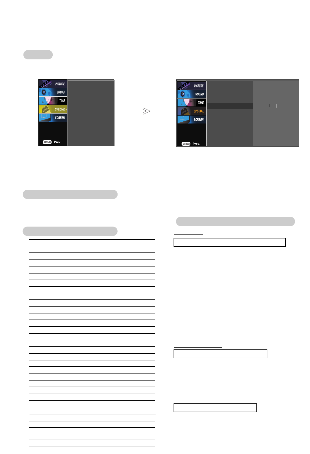
1. Press the MENU button and then use DD / EEbutton to select the SPECIAL menu.
2. Press the GGbutton and then use DD / EEbutton to select XD Demo.
3. Press the GGbutton to begin
XD Demo
.
4. Press the EXIT button to stop
XD Demo
.
XD Demo
XD Demo
- Use it to see the difference between XD Demo on and XD Demo off.
- XD demo is not available for RGB (PC) and HDMI (PC) sources.
Low Power
Low Power
- Low power reduces the plasma display's power consumption.
1. Press the MENU button and then use DD / EEbutton to select the SPECIAL menu.
2. Press the GGbutton and then use DD / EEbutton to select Low power.
3. Press the GGbutton and then use DD / EEbutton to select On or Off.
• When you select On, the screen darkens.
4. Press the ENTER button to save the new settings.
Language
Child lock
ISM Method
Set ID
Tile mode
Low power
XD Demo
Language
Child lock
ISM Method
Set ID
Tile mode
Low power G
XD Demo
On
Off
Language
Child lock
ISM Method
Set ID
Tile mode
Low power
XD Demo
Language
Child lock
ISM Method
Set ID
Tile mode
Low power
XD Demo GTo start
Owner’s Manual 31
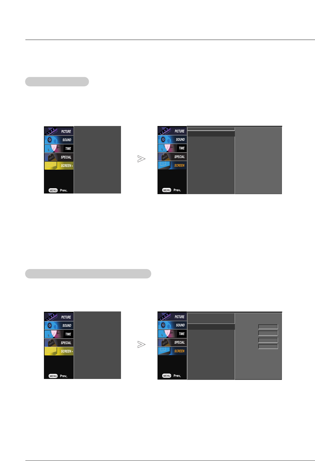
Auto
Auto Adjustment
Adjustment
- RGB (PC) mode only
- Automatically adjusts picture position and minimizes image shaking.
- After adjustment, if the image is still not correct, your set is functioning properly but needs further adjustment.
- The Auto config. and Manual config. are not active in HDMI mode.
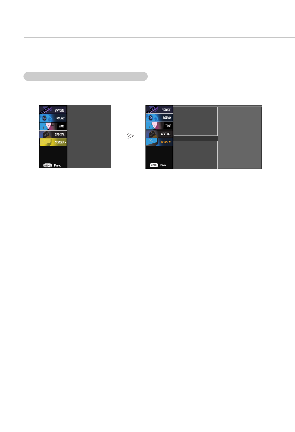
1. Press the MENU button and then use DD /EEbutton to select the SCREEN menu.
2. Press the GGbutton and then use DD /EEbutton to select Auto config..
3. Press the GGbutton to run Auto configure.
• When Auto config. has finished, OK will be seen on the screen.
• If the position of the image is still not correct, try Auto adjustment again.
4. In RGB (PC) mode, if the image needs to be adjusted more after using Auto config., you can make further adjustments with
the Manual config. option.
Auto config.
Manual config.
XGA Mode
ARC
Reset
Auto config. G
Manual config.
XGA Mode
ARC
Reset
To set
Manual Configure (RGB-PC mode only)
Manual Configure (RGB-PC mode only)
Auto config.
Manual config.
XGA Mode
ARC
Reset
Auto config.
Manual config. G
XGA Mode
ARC
Reset
- If the image still isn’t clear after auto adjustment is completed and especially if characters are still jittery, adjust the pic-
ture Phase manually.
- To correct the screen size, adjust Clock.
1. Press the MENU button and then use DD / EEbutton to select the SCREEN menu.
2. Press the GGbutton and then use DD / EEbutton to select Manual config..
3. Press the GGbutton and then use DD / EEbutton to to select Phase,Clock,
H-Position or V-Position.
4. Use the FF / GGbutton to make appropriate adjustments.
• The Phase adjustment range is 0 ~ 63.
• The Clock adjustment range is -128 ~ +128.
5. Press the ENTER button to save.
Phase 0
Clock 0
H-Position 0
V-Position 0
Screen Menu Options
Screen Menu Options
32 Plasma Monitor
Operation
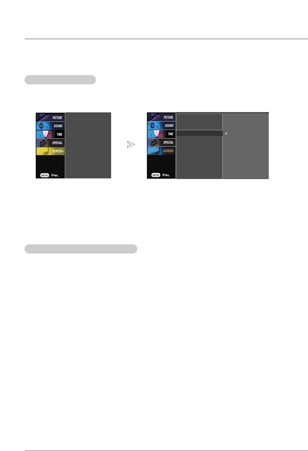
Picture Size (Aspect Ratio) Control
Picture Size (Aspect Ratio) Control
- This feature allows an analog picture with a 4:3 aspect ratio is displayed on your TV. When you receive an
analog picture with a 4:3 aspect ratio on your 16:9 TV, you need to specify how the picture is to be displayed.
- If a fixed image is displayed on the screen for a long time, the image may become imprinted on the screen
This phenomenon is common to all manufactures and in consequence the manufactures warranty does not
cover the product bearing this phenomenon.
1. Press the ARC button repeatedly to select the desired picture format. You can also select picture format in the
SCREEN menu.
• 4:3
- Choose 4:3 when you want to view a picture with an original 4:3 aspect ratio, with black bars appearing at both
the left and right sides.
• 16:9
- Choose 16:9 when you want to adjust the picture horizontally, in a linear proportion to fill the entire screen.
• Zoom 1
- Choose Zoom 1 when you want to view the picture without any alteration. However, the top and bottom por-
tions of the picture will be cropped.
• Zoom 1
- Choose Zoom 2 when you want the picture to be altered, both vertically extended and cropped. The picture
taking a halfway trade off between alteration and screen coverage.
- To see a normal picture, match the resolution of XGA mode (1024x768, 1280x768, 1360x768, 1366x768) with the selection for
XGA mode in the SCREEN menu.
1. Press the MENU button and then use DD /EEbutton to select the SCREEN menu.
2. Press the GGbutton and then use DD /EEbutton to select XGA Mode.
3. Press the GGbutton and then use DD /EEbutton to select the desired XGA resolution.
4. Press the ENTER button to save.
Selecting XGA
Selecting XGA mode
mode
Auto config.
Manual config.
XGA Mode
ARC
Reset
Auto config.
Manual config.
XGA Mode G
ARC
Reset
1024 x 768
1280 x 768
1360 x 768
1366 x 768
Owner’s Manual 33
Operation
Initializing (Reset to original factory value)
Initializing (Reset to original factory value)
1. Press the MENU button and then use DD / EEbutton to select the SCREEN menu.
2. Press the GGbutton and then use DD / EEbutton to select Reset.
3. Press the GGbutton.
- Use the Reset option to initialize the adjusted settings.
Auto config.
Manual config.
XGA Mode
ARC
Reset
Auto config. G
Manual config.
XGA Mode
ARC
Reset To set
34 Plasma Monitor
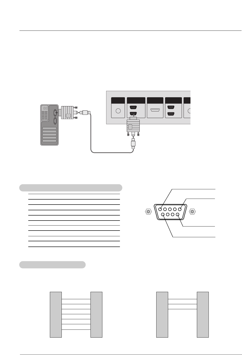
No. Pin Name
1 No Connection
2 RXD (Receive data)
3 TXD (Transmit data)
4 DTR (DTE side ready)
5 GND
6 DSR (DCE side ready)
7 RTS (Ready to send)
8 CTS (Clear to send)
9 No Connection
1
5
6
9
2
3
5
4
6
7
8
RXD
TXD
GND
DTR
DSR
RTS
CTS
TXD
RXD
GND
DSR
DTR
CTS
RTS
PC
7-Wire Configuration
(Standard RS-232C cable)
D-Sub 9
3
2
5
6
4
8
7
PDP
D-Sub 9
2
3
5
4
6
7
8
RXD
TXD
GND
DTR
DSR
RTS
CTS
TXD
RXD
GND
DTR
DSR
RTS
CTS
PC
3- Wire Configuration
(Not standard)
D-Sub 9
3
2
5
4
6
7
8
PDP
D-Sub 9
- Connect the RS-232C input jack to an external control device (such as a computer or an A/V control system)
and control the Monitor’s functions externally.
- Connect the serial port of the control device to the RS-232C jack on the Monitor back panel.
- RS-232C connection cables are not supplied with the Monitor.
T
Type of Connector: D-Sub 9-pin Male
ype of Connector: D-Sub 9-pin Male
RS-232C Configurations
RS-232C Configurations
External Control Device Setup
External Control Device Setup
OUT
IN
REMOTE
CONTROL IN
HDMI/DVI IN
RS-232C
(CONTROL&SERVICE)
IN
OUT
RGB AUD
(RGB
Operation
Owner’s Manual 35
External Control Device Setup
Transmission
* [Command 1]: k, j, m
* [Command 2]: To control PDP set.
* [Set ID]: You can adjust the set ID to choose desired moni-
tor ID number in Special menu. Adjustment range
is 1 ~ 99. When selecting Set ID ‘0’, every con-
nected PDP set is controlled. Set ID is indicated
as decimal (1~99) on menu and as Hexa decimal
(0x0~0x63) on transmission/receiving protocol.
* [DATA]: To transmit command data.
Transmit ‘FF’data to read status of command.
* [Cr]: Carriage Return
ASCII code ‘0x0D’
* [ ]: ASCII code ‘space (0x20)’
[Command1][Command2][ ][Set ID][ ][Data][Cr]
OK Acknowledgement
* The Monitor transmits ACK (acknowledgement) based on
this format when receiving normal data. At this time, if the
data is data read mode, it indicates present status data. If
the data is data write mode, it returns the data of the PC
computer.
[Command2][ ][Set ID][ ][OK][Data][x]
Error Acknowledgement
* The Monitor transmits ACK (acknowledgement) based on
this format when receiving abnormal data from
non-viable functions or communication errors.
[Command2][ ][Set ID][ ][NG][x]
T
Transmission / Receiving Protocol
ransmission / Receiving Protocol
01. Power k a 0 ~ 1
02. Input Select k b 1 ~ 9
03. Aspect Ratio k c 0 ~ 3
04. Screen Mute k d 0 ~ 1
05. Volume Mute k e 0 ~ 1
06. Volume Control k f 0 ~ 64
07. Contrast k g 0 ~ 64
08. Brightness k h 0 ~ 64
09. Color k i 0 ~ 64
10. Tint k j 0 ~ 64
11. Sharpness k k 0 ~ 64
12. OSD Select k l 0 ~ 1
13.
Remote Control Lock Mode
k m 0 ~ 1
14. PIP/DW k n 0 ~ 3
15. PIP Position k q 0 ~ 3
16. Treble k r 0 ~ 64
17. Bass k s 0 ~ 64
18. Balance k t 0 ~ 64
19. Color Temperature k u 0 ~ 3
20. Red adjustment k v 0 ~ 14
21. Green adjustment k w 0 ~ 14
22. Blue adjustment k $ 0 ~ 14
23. PIP Input Select k y 1 ~ 9
24. Abnormal State k z 0 ~ a
25. ISM Method j p 0 ~ 3
26. Low Power j q 0 ~ 1
27. Picture Size Setting j t 0 ~oa
for DW mode
28. Auto Configure j u 1
29. Key m c
Key code
COMMAND 1 COMMAND 2 DATA
(Hexadecimal)
Command Reference List
Command Reference List
Set ID
Set ID
- Use this function to specify a monitor ID number.
- Refer to ‘Real Data Mapping 1’. See page 38.
1. Press the MENU button and then use the DD /EEbutton to select the SPECIAL menu.
2. Press the GGbutton and then use DD /EEbutton to select Set ID.
3. Press the GGbutton and then use F / Gbutton to adjust Set ID to choose the desired monitor ID number.
• The adjustment range of Set ID is 1 ~ 99.
• Baud rate : 9600 bps (UART)
• Data length : 8 bits
• Parity : None
• Stop bit : 1 bit
• Communication code : ASCII code
Communication Parameters
Communication Parameters
Data 1: Illegal Code
2: Not supported function
Language
Child lock
ISM Method
Set ID
Tile mode
Low power
XD Demo
Language
Child lock
ISM Method
Set ID G
Tile mode
Low power
XD Demo
1
36 Plasma Monitor
02. Input Select (Command 2:b) (Main Picture Input)
GTo select input source for the Monitor.
You can also select an input source using the INPUT
button on the Monitor's remote control.
Transmission
Data 2 : AV
4 : Component1
5 : Component2
6 : RGB (DTV)
7 : RGB (PC)
8 : HDMI (DTV)
9 : HDMI (PC)
[k][b][ ][Set ID][ ][Data][Cr]
Acknowledgement
[b][ ][Set ID][ ][OK][Data][x]
01. Power (Command 2:a)
GTo control Power On/Off of the Monitor.
Transmission
Data 0 : Power Off 1 : Power On
[k][a][ ][Set ID][ ][Data][Cr]
Acknowledgement
[a][ ][Set ID][ ][OK][Data][x]
GTo show Power On/Off.
Transmission
[k][a][ ][Set ID][ ][FF][Cr]
Acknowledgement
Data 0 : Power Off 1 : Power On
* In a like manner, if other functions transmit ‘FF’data
based on this format, Acknowledgement data feedback
presents status about each function.
[a][ ][Set ID][ ][OK][Data][x]
03. Aspect Ratio (Command 2:c) (Main picture format)
GTo adjust the screen format.
You can also adjust the screen format using the ARC
(Aspect Ratio Control) button on remote control or in the
Screen menu.
Transmission
Data 0 : Normal screen (4:3)
1 : Wide screen (16:9)
2 : Wide screen (Horizon)
3 : Full screen (Zoom)
[k][c][ ][Set ID][ ][Data][Cr]
Acknowledgement
[c][ ][Set ID][ ][OK][Data][x]
05. Volume Mute (Command 2:e)
GTo control volume mute on/off.
You can also adjust mute using the MUTE button on
remote control.
Transmission
Data 0 : Volume mute on (Volume off)
1 : Volume mute off (Volume on)
[k][e][ ][Set ID][ ][Data][Cr]
Acknowledgement
[e][ ][Set ID][ ][OK][Data][x]
04. Screen Mute (Command 2:d)
GTo select screen mute on/off.
Transmission
Data 0 : Screen mute off (Picture on)
1 : Screen mute on (Picture off)
[k][d][ ][Set ID][ ][Data][Cr]
Acknowledgement
[d][ ][Set ID][ ][OK][Data][x]
06. Volume Control (Command 2:f)
GTo adjust volume.
You can also adjust volume with the volume buttons
on remote control.
Transmission
Data Min : 0 ~ Max : 64
•Refer to ‘Real data mapping 1’. See page 38.
[k][f][ ][Set ID][ ][Data][Cr]
Acknowledgement
[f][ ][Set ID][ ][OK][Data][x]
Data 2 : AV
4 : Component1
5 : Component2
6 : RGB (DTV)
7 : RGB (PC)
8 : HDMI (DTV)
9 : HDMI (PC)
Data 0 : Screen mute off (Picture on)
1 : Screen mute on (Picture off)
Data 0 : Volume mute on (Volume off)
1 : Volume mute off (Volume on)
Data Min : 0 ~ Max : 64
External Control Device Setup
07. Contrast (Command 2:g)
GTo adjust screen contrast.
You can also adjust contrast in the picture menu.
Transmission
Data Min : 0 ~ Max : 64
•Refer to ‘Real data mapping 1’. See page 38.
[k][g][ ][Set ID][ ][Data][Cr]
Acknowledgement
[g][ ][Set ID][ ][OK][Data][x]
Data Min : 0 ~ Max : 64
Owner’s Manual 37
External Control Device Setup
13. Remote Control Lock Mode (Command2:m)
GTo lock the remote control and front panel controls on the
monitor
Transmission
[k][m][ ][Set ID][ ][Data][Cr]
Acknowledgement
Data 0: lock off 1: lock on
•If you’re not using the remote control and front panel con-
trols on the monitor, use this mode. When main power is
on/off, remote control lock is released.
[m][ ][Set ID][ ][OK][Data][x]
GTo adjust the screen sharpness.
You can also adjust sharpness in the Picture menu.
Transmission
11. Sharpness (Command2:k)
Data Min: 0 ~ Max: 64
•Refer to ‘Real data mapping 1’. See page 38.
[k][k][ ][Set ID][ ][Data][Cr]
Acknowledgement
[k][ ][Set ID][ ][OK][Data][x]
12. OSD Select (Command2:l)
GTo select OSD (On Screen Display) on/off.
Transmission
[k][l][ ][Set ID][ ][Data][Cr]
Acknowledgement
Data 0: OSD off 1: OSD on
[l][ ][Set ID][ ][OK][Data][x]
09. Color (Command2:i)
GTo adjust the screen color.
You can also adjust color in the Picture menu.
Transmission
Data Min : 0 ~ Max : 64
•Refer to ‘Real data mapping 1’. See page 38.
[k][i][ ][Set ID][ ][Data][Cr]
Acknowledgement
[i][ ][Set ID][ ][OK][Data][x]
10. Tint (Command2:j)
GTo adjust the screen tint.
You can also adjust tint in the Picture menu.
Transmission
Data Red : 0 ~ Green : 64
•Refer to ‘Real data mapping 1’. See page 38.
[k][j][ ][Set ID][ ][Data][Cr]
Acknowledgement
[j][ ][Set ID][ ][OK][Data][x]
08. Brightness (Command2:h)
GTo adjust screen brightness.
You can also adjust brightness in the Picture menu.
Transmission
Data Min : 0 ~ Max : 64
•Refer to ‘Real data mapping 1’. See page 38.
[k][h][ ][Set ID][ ][Data][Cr]
Acknowledgement
[h][ ][Set ID][ ][OK][Data][x]
Data Min : 0 ~ Max : 64
Data Min : 0 ~ Max : 64
Data Red : 0 ~ Green : 64
Data Min : 0 ~ Max : 64
Data 0: OSD off 1: OSD on
Data 0: lock off 1: lock on
14. Balance (Command2:t)
GTo adjust balance.
You can also adjust balance in the Sound menu.
Transmission
Data Min: 0 ~ Max: 64
•Refer to ‘Real data mapping 1’. See page 38.
[k][t][ ][Set ID][ ][Data][Cr]
Acknowledgement
[t][ ][Set ID][ ][OK][Data][x]
Data Min: 0 ~ Max: 64
15. Color Temperature (Command2:u)
GTo adjust color temperature.
You can also adjust ACC in the Picture menu.
Transmission
Data 0: Normal 1: Cool 2: Warm 3: User
[k][u][ ][Set ID][ ][Data][Cr]
Acknowledgement
[u][ ][Set ID][ ][OK][Data][x]
Data 0: Normal 1: Cool 2: Warm 3: User
38 Plasma Monitor
External Control Device Setup
17. ISM Method (Command2:p)
GTo avoid having a fixed image remain on screen.
Transmission
Data 1: Inversion
2: Orbiter
3: Orb.+Inv.
4: White Wash
8: Normal
[j][p][ ][Set ID][ ][Data][Cr]
Acknowledgement
[p][ ][Set ID][ ][OK][Data][x]
18. Auto Configure (Command2:u)
GTo adjust picture position and minimize image shaking
automatically. Auto Configure only works in RGB-PC
mode.
Transmission
Data 1
•Refer to ‘Real data mapping1’. See page 38.
[j][u][ ][Set ID][ ][Data][Cr]
Acknowledgement
[u][ ][Set ID][ ][OK][Data][x]
16. Abnormal State (Command2:z)
GTo recognize an abnormal state.
Transmission
Data 0: Power on(signal)
1: Power on(No signal)
2: Remote control off
3: Sleep time off
4: RS-232C off
5: 5V monitor off
6: AC detect off
7: Fan Alarm off
8: Off timer off
9: No signal off
a: Connection Detect off
[k][z][ ][Set ID][ ][FF][Cr]
Acknowledgement
[z][ ][Set ID][ ][OK][Data][x]
Data FF:Read
Data 1: Inversion
2: Orbiter
3: Orb.+Inv.
4: White Wash
8: Normal
Data 1
19. Key (Command2:c)
GTo adjust Key code for IR remote control.
Transmission
Data Key code : Refer to See page 41.
[m][c][ ][Set ID][ ][Data][Cr]
Acknowledgement
[c][ ][Set ID][ ][OK][Data][x]
* If you do not press any button within 2 hours after the monitor turns
on with the On Timer function, the monitor will automatically revert to
standby mode.
20. Tile Mode (Command : d d)
GChange a Tile Mode.
Transmission
Data 0: Tile mode is off.
12: 1 x 2 mode (column x row)
13: 1 x 3 mode
14: 1 x 4 mode
44: 4 x 4 mode
[d][d][ ][Set ID][ ][Data][Cr]
Acknowledgement
[d][ ][Set ID][ ][OK][Data][x]
Data 0: Tile mode is off.
12: 1 x 2 mode (column x row)
13: 1 x 3 mode
14: 1 x 4 mode
44: 4 x 4 mode
* Real data mapping 1
0 : Step 0
A : Step 10 (SET ID 10)
F : Step 15 (SET ID 15)
10 : Step 16 (SET ID 16)
63 : Step 99 (SET ID 99)
64 : Step 100
* Real data mapping 2
0: -10
1: - 9
2 : - 8
A : 0
12 : + 8
13 : + 9
14 : + 10
Owner’s Manual 39
External Control Device Setup
26. Low Power (Command2:q)
GTo control the low power function on/off.
Transmission
Data 0: Low power off
1: Low power on
[j][q][ ][Set ID][ ][Data][Cr]
Acknowledgement
[q][ ][Set ID][ ][OK][Data][x]
Data 0: Low power off
1: Low power on
21. Tile H Size (Command : d g)
GTo set the Horizontal size.
Transmission
Data Min: 0 ~ Max: 64
[d][g][ ][Set ID][ ][Data][Cr]
Acknowledgement
[g][ ][Set ID][ ][OK][Data][x]
Data Min: 0 ~ Max: 64
22. Tile V Size (Command : d h)
GTo set the Vertical size.
Transmission
Data Min: 0 ~ Max: 64
[d][h][ ][Set ID][ ][Data][Cr]
Acknowledgement
[h][ ][Set ID][ ][OK][Data][x]
Data Min: 0 ~ Max: 64
23. Tile ID Set (Command : d i)
GTo assign the Tile ID for Tiling function.
Transmission
Data Min: 0 ~ Max: 64
[d][i][ ][Set ID][ ][Data][Cr]
Acknowledgement
[i][ ][Set ID][ ][OK][Data][x]
Data Min: 0 ~ Max: 64
24. Elapsed time return (Command : d l)
GTo read the elapsed time.
Transmission
* The data is always FF(in Hex).
[d][l][ ][Set ID][ ][Data][Cr]
Acknowledgement
[l][ ][Set ID][ ][OK][Data][x]
* The data means used hours. (Hexadecimal code)
40 Plasma Monitor
G Connect your wired remote control to the Remote Control port on the Monitor.
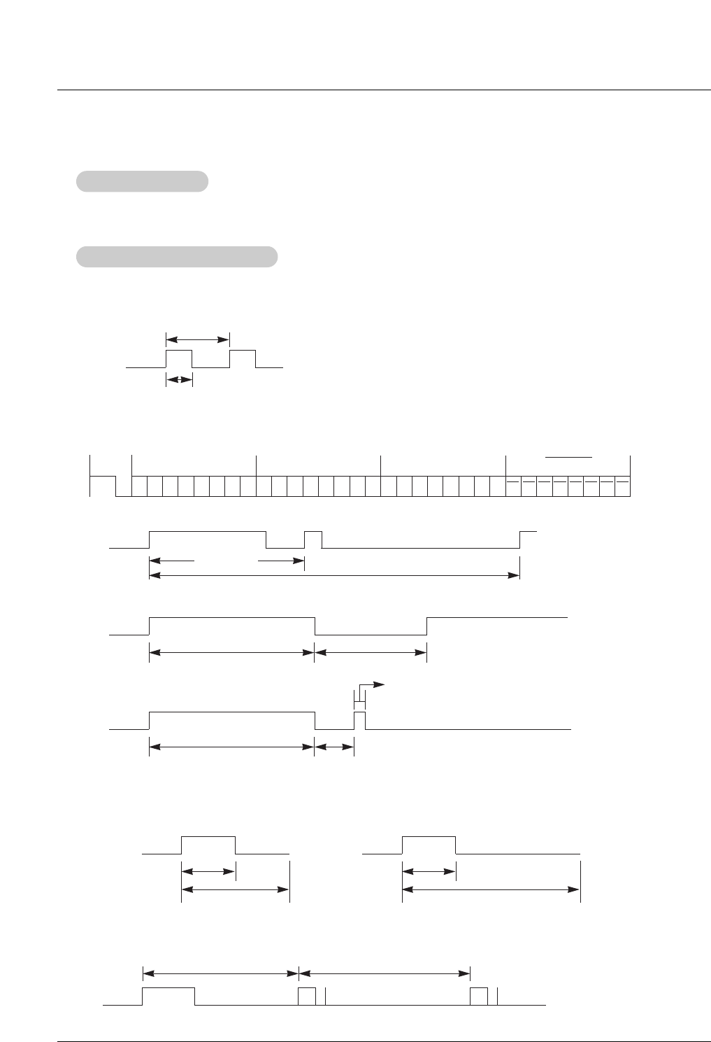
G Output waveform
Single pulse, modulated with 37.917KHz signal at 455KHz
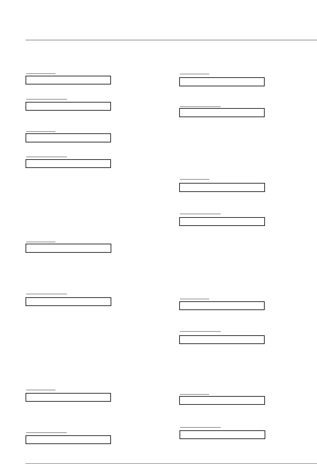
G Configuration of frame
G Repeat code
G Lead code
• 1st frame
Low
custom code
Lead
code
High
custom code Data code Data code
TC
Tf
T1
C0
Carrier frequency
FCAR = 1/TC= fOSC/12
Duty ratio = T1/TC= 1/3
• Repeat frame
C1 C2 C3 C4 C5 C6 C7 C0 C1 C2 C3 C4 C5 C6 C7 D0 D1 D2 D3 D4 D5 D6 D7 D0 D1 D2 D3 D4 D5 D6 D7
Repeat code
9 ms 4.5 ms
0.55 ms
9 ms
2.25 ms
G Bit description
G Frame interval : Tf
The waveform is transmitted as long as a key is depressed.
• Bit “0”
Tf Tf
Tf=108ms @455KHz
0.56 ms 0.56 ms
1.12 ms
• Bit “1”
2.24 ms
How to Connect
How to Connect
Remote Control IR Code
Remote Control IR Code
IR Code
IR Code
External Control Device Setup
Owner’s Manual 41
IR Code
Number Key 0
Number Key 1
Number Key 2
Number Key 3
Number Key 4
Number Key 5
Number Key 6
Number Key 7
Number Key 8
Number Key 9
SLEEP
MUTE
POWER
VOL+
VOL-
CH+
CH-
APC
DASP
ENTER (Á)
AII INPUT SELECT
MENU
ARC
Window Position
Window Size
F
G
D
E
EXIT
PIP
XD
PIP Input
DW
Video
HDMI2
Key lock
Index
Auto config.
Input video1
Input video2
Input Component 1
Input Component 2
Input RGB
Input HDMI1/DVI
10
11
12
13
14
15
16
17
18
19
0E
09
08
02
03
00
01
4D
52
44
0B
43
79
62
64
07
06
40
41
5B
60
92
61
6B
CD
CE
3E
75
99
5A
D0
BF
D4
D5
C6
R/C Button
R/C Button
R/C Button
R/C Button
R/C Button
R/C Button
R/C Button
R/C Button
R/C Button
R/C Button
R/C Button
R/C Button
R/C Button (Power On/Off)
R/C Button
R/C Button
R/C Button
R/C Button
R/C Button
R/C Button
R/C Button
R/C Button
R/C Button
R/C Button (4:3/16:9/Horizon/Zoom mode Selection)
R/C Button
R/C Button
R/C Button
R/C Button
R/C Button
R/C Button
R/C Button
R/C Button
R/C Button
R/C Button
R/C Button
R/C Button
R/C Button
R/C Button
R/C Button
Discrete IR Code (Only RGB mode)
Discrete IR Code (Input Video 1 Selection)
Discrete IR Code (Input Video 2 Selection)
Discrete IR Code (Input Component 1 Selection)
Discrete IR Code (Input Component 2 Selection)
Discrete IR Code (Input RGB Selection)
Discrete IR Code (Input HDMI1/DVI Selection)
Code (Hexa) Function Note
42 Plasma Monitor
Programming the Remote
The video function does not work.
No picture &
No sound
No or poor color
or poor picture
•Adjust Color in menu option.
•Keep a sufficient distance between the product and the VCR.
•Try another channel. The problem may be with the broadcast.
•Are the video cables installed properly?
•Activate any function to restore the brightness of the picture.
Picture appears
slowly after
switching on
•This is normal, the image is muted during the product startup process.
Please contact your service center, if the picture has not appeared after five
minutes.
Horizontal/verti-
cal bars or pic-
ture shaking
•Check for local interference such as an electrical appliance or power tool.
Poor reception on
some channels
•Station or cable product experiencing problems, tune to another station.
•Station signal is weak, reorient antenna to receive weaker station.
•Check for sources of possible interference.
Lines or streaks
in pictures •Check antenna (Change the direction of the antenna).
•Check whether the product is turned on.
•Try another channel. The problem may be with the broadcast.
•Is the power cord inserted into wall power outlet?
•Check your antenna direction and/or location.
•Test the wall power outlet, plug another product’s power cord into the outlet
where the product’s power cord was plugged in.
The remote control
doesn’t work
The operation does not work normally.
•Check to see if there is any object between the product and the remote
control causing obstruction.
•Are batteries installed with correct polarity (+ to +, - to -)?
•Correct remote operating mode set: TV, VCR etc.?
•Install new batteries.
Power is suddenly
turned off
•Is the sleep timer set?
•Check the power control settings. Power interrupted
•No broadcast on station tuned with Auto off activated.
T
Troubleshooting Checklist
roubleshooting Checklist
Owner’s Manual 43
Programming the Remote
The audio function does not work.
Picture OK &
No sound
•Press the VOL or VOLUME button.
•Sound muted? Press MUTE button.
•Try another channel. The problem may be with the broadcast.
•Are the audio cables installed properly?
Unusual sound
from inside the
product
•A change in ambient humidity or temperature may result in an unusual
noise when the product is turned on or off and does not indicate a fault with
the product.
No output from one
of the speakers
•Adjust Balance in menu option.
Screen color is
unstable or single
color
•Check the signal cable.
•Reinstall the PC video card.
The signal is out of
range.
There is a problem in PC mode.
(Only PC mode applied)
•Adjust resolution, horizontal frequency, or vertical frequency.
•Check the input source.
Vertical bar or
stripe on back-
ground &
Horizontal Noise &
Incorrect position
•Work the Auto configure or adjust clock, phase, or H/V position. (Option)

44 Plasma Monitor
Troubleshooting Checklist
1. Here’s a great way to keep the dust off your screen for a while. Wet a soft cloth in a mixture of lukewarm water
and a little fabric softener or dish washing detergent. Wring the cloth until it’s almost dry, and then use it to wipe
the screen.
2. Make sure the excess water is off the screen, and then let it air-dry before you turn on your TV.
To remove dirt or dust, wipe the cabinet with a soft, dry, lint-free cloth.
Please do not use a wet cloth.
If you expect to leave your TV dormant for a long time (such as a vacation), it’s a good idea to
unplug the power cord to protect against possible damage from lightning or power surges.
- Early malfunctions can be prevented. Careful and regular cleaning can extend the amount of time you will have
your new TV. Be sure to turn the power off and unplug the power cord before you begin any cleaning.
Cleaning the Screen
Cleaning the Screen
Cleaning the Cabinet
Cleaning the Cabinet
Extended
Extended Absence
Absence
Maintenance
Maintenance
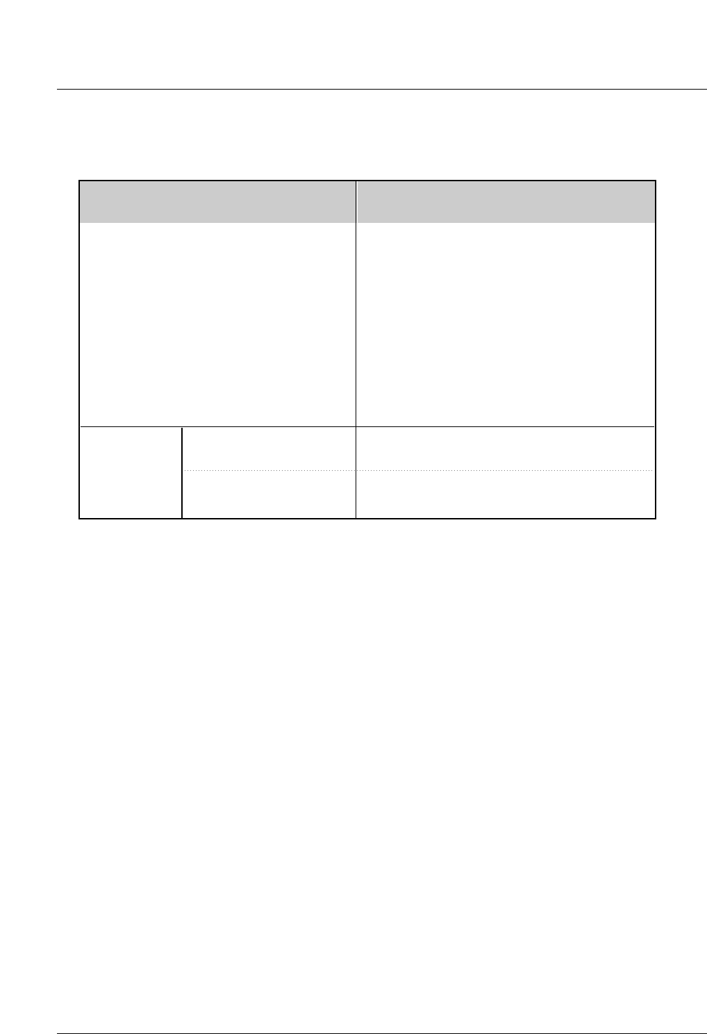
Owner’s Manual 45
Specifications
•The specifications shown above may change without notice for quality improvement.
Product Specifications
Product Specifications
MODELS
Width (inches / mm)
Height (inches / mm)
Depth (inches / mm)
Weight (pounds / kg)
Power requirement
Resolution
42PM4M
(42PM4M-WA)
42.0 / 1066.0
25.6 / 650.0
3.8 / 97.5
66.1 / 30.0
AC100-240V ~ 50/60Hz
1920 x 1080 (Dot)
32 ~ 104°F (0 ~ 40°C)
Less than 80%
-4 ~ 140°F (-20 ~ 60°C)
Less than 85%
Environmental
condition
Operating Temperature
Operating Humidity
Storage Temperature
Storage Humidity