LG Electronics USA 42PX5DUB Plasma Display Panel User Manual 528Ben
LG Electronics USA Plasma Display Panel 528Ben
Contents
- 1. User Manual Part 1
- 2. User Manual Part 2
User Manual Part 1

Please read this manual carefully and completely before
operating your TV.
Retain this manual for future reference.
Record model number and serial number of the TV in the
spaces provided below.
See the label attached on the back cover and relate this
information to your dealer if you require service.
Model Number :
Serial Number :
MODELS: 42PX4D/42PX5D
42PX4D-UB/42PX5D-UB
LG Electronics U.S.A., Inc.
TM
R
TruSurround XT
PLASMA TV
OWNER’S MANUAL
2 Plasma TV
Warning/Caution
WARNING/CAUTION:
TO REDUCE THE RISK OF ELECTRIC SHOCK DO NOT REMOVE COVER (OR BACK). NO USER
SERVICEABLE PARTS INSIDE. REFER TO QUALIFIED SERVICE PERSONNEL.
The lightning flash with arrowhead symbol, within an equilateral triangle, is intended to alert the user to
the presence of uninsulated “dangerous voltage” within the product’s enclosure that may be of suffi-
cient magnitude to constitute a risk of electric shock to persons.
The exclamation point within an equilateral triangle is intended to alert the user to the presence of
important operating and maintenance (servicing) instructions in the literature accompanying the appli-
ance.
WARNING/CAUTION:
TO PREVENT FIRE OR SHOCK HAZARDS, DO NOT EXPOSE THIS PRODUCT TO RAIN OR MOISTURE.
FCC NOTICE
• A Class B digital device
This equipment has been tested and found to comply with the limits for a Class B digital device, pursuant to Part
15 of the FCC Rules. These limits are designed to provide reasonable protection against harmful interference in
a residential installation. This equipment generates, uses and can radiate radio frequency energy and, if not
installed and used in accordance with the instructions, may cause harmful interference to radio communications.
However, there is no guarantee that interference will not occur in a particular installation. If this equipment does
cause harmful interference to radio or television reception, which can be determined by turning the equipment off
and on, the user is encouraged to try to correct the interference by one or more of the following measures:
- Reorient or relocate the receiving antenna.
- Increase the separation between the equipment and receiver.
- Connect the equipment into an outlet on a circuit different from that to which the receiver is connected.
- Consult the dealer or an experienced radio/TV technician for help.
• Any changes or modifications not expressly approved by the party responsible for compli-
ance could void the user’s authority to operate the equipment.
.
CAUTION:
Do not attempt to modify this product in any way without written authorization from LG Electronics. Unauthorized mod-
ification could void the user’s authority to operate this product.
COMPLIANCE:
The responsible party for this product’s compliance is:
LG Electronics U.S.A., Inc
1000 Sylvan Avenue, Englewood Cliffs, NJ 07632
1-800-243-0000
http://www.lgusa.com
WARNING
RISK OF ELECTRIC SHOCK
DO NOT OPEN
/CAUTION
WARNING/CAUTION
TO REDUCE THE RISK OF FIRE AND ELECTRIC SHOCK, DO NOT EXPOSE THIS PRODUCT TO
RAIN OR MOISTURE.
W
Warning/Caution
arning/Caution

Owner’s Manual 3
TV Guide On Screen Notices for U.S.A.
TV Guide On Screen Notices for U.S.A.
In the United States, TV GUIDE and other related marks are registered marks of Gemstar-TV Guide International, Inc. and/or
one of its affiliates. In Canada, TV GUIDE is a registered mark of Transcontinental Inc., and is used under license by
Gemstar-TV Guide International, Inc.
The TV Guide On Screen system is protected by one or more of the following issued United States patents 6,498,895,
6,418,556, 6,331,877; 6,239,794; 6,154,203; 5,940,073; 4,908,713; 4,751,578; 4,706,121.
The TV Guide On Screen system is manufactured under license from Gemstar-TV Guide International, Inc. and/or one of its
affiliates.
Digital Cable Compatibility
Digital Cable Compatibility
This digital television is capable of receiving basic analog, digital basic and digital premium cable television programming by
direct connection to a cable system providing such programming. A security card provided by your cable operator is required
to view encrypted digital programming. Certain advanced interactive digital cable services such as video-on-demand, cable
operator enhanced program (For example, electronic program guide provided by the cable operator), and data enhanced
television service may require the use of a set top box. For more information contact your local cable operator.
Use of the CableCARDTM TradeMark.
“CableCARDTM is a trademark of Cable Television Laboratories, Inc.”
Trademark Notice
Aux Etats Unis TV GUIDE et d’autres marques relatives sont des marques déposées de Gemstar-TV Guide International,
Inc. et/ou d’une de ses sociétés affiliées. Au Canada TV GUIDE est une marque déposée de Transcontinental Inc., utilisée
sous licence de Gemstar-TV Guide International, Inc.
Le système TV Guide On Screen est fabriqués sous licence de Gemstar-TV Guide International, Inc. et/ou d’une de ses sociétés
affiliées.
Le système TV Guide On Screen est protégés par un ou plusieurs brevets émis aux Etats Unis, comme le 6,498,895,
6,418,556, 6,331,877; 6,239,794; 6,154,203; 5,940,073; 4,908,713; 4,751,578; 4,706,121.
License Notice
Patent Notice

4 Plasma TV
Safety Instructions
IMPORTANT SAFETY INSTRUCTIONS
Important safety instructions shall be provided with each apparatus. This information shall be given in a separate booklet or
sheet, or be located before any operating instructions in an instruction for installation for use and supplied with the appara-
tus. This information shall be given in a language acceptable to the country where the apparatus is intended to be used. The
important safety instructions shall be entitled “Important Safety Instructions”. The following safety instructions shall be includ-
ed where applicable, and, when used, shall be verbatim as follows. Additional safety information may be included by adding
statements after the end of the following safety instruction list. At the manufacturer’s option, a picture or drawing that illus-
trates the intent of a specific safety instruction may be placed immediately adjacent to that safety instruction :
1. Read these instructions.
2. Keep these instructions.
3. Heed all warnings.
4. Follow all instructions.
5. Do not use this apparatus near water.
6. Clean only with dry cloth.
7. Do not block any ventilation openings. Install in accordance with the manufacturer’s instructions.
8. Do not install near any heat sources such as radiators, heat registers, stoves, or other apparatus (including ampli-
fiers)that produce heat.
9. Do not defeat the safety purpose of the polarized or grounding-type plug. A polarized plug has two blades with
one wider than the other. A grounding type plug has two blades and a third grounding prong, The wide blade or the
third prong are provided for your safety. If the provided plug does not fit into your outlet, consult an electrician for
replacement of the obsolete outlet.
10. Protect the power cord from being walked on or pinched particularly at plugs, convenience receptacles, and the
point where they exit from the apparatus.
11. Only use attachments/accessories specified by the manufacturer.
12. Use only with the cart, stand, tripod, bracket, or table specified by the manufacturer, or sold with the apparatus.
When a cart is used, use caution when moving the cart/apparatus combination to avoid injury from tip-over.
Safety Instructions
Safety Instructions
PORTABLE CART WARNING

Owner’s Manual 5
Safety Instructions
13. Unplug this apparatus during lightning storms or when unused for long periods of time.
14. Refer all servicing to qualified service personnel. Servicing is required when the apparatus has been damaged
in any way, such as power-supply cord or plug is damaged, liquid has been spilled or objects have fallen into
the apparatus, the apparatus has exposed to rain or moisture, does not operate normally, or has been dropped.
15. CAUTION concerning the Power Cord :
Most appliances recommend they be placed upon a dedicated circuit; that
is, a single outlet circuit which powers only that appliance and has no
additional outlets or branch circuits. Check the specification page of
this owner's manual to be certain.
Do not overload wall outlets. Overloaded wall outlets, loose or damaged
wall outlets, extension cords, frayed power cords, or damaged or
cracked wire insulation are dangerous. Any of these conditions could
result in electric shock or fire. Periodically examine the cord of your
appliance, and if its appearance indicates damage or deterioration,
unplug it, discontinue use of the appliance, and have the cord replaced
with an exact replacement part by an authorized servicer.
Protect the power cord from physical or mechanical abuse, such as being
twisted, kinked, pinched, closed in a door, or walked upon. Pay
particular attention to plugs, wall outlets, and the point where the
cord exits the appliance.
16. Outdoor Use Marking :
WARNING - To Reduce The Risk Of Fire Or Electric Shock, Do Not Expose This Appliance To Rain Or Moisture.
17. Wet Location Marking :
Apparatus shall not be exposed to dripping or splashing and no objects filled with liquids, such as vases, shall
be placed on the apparatus.

6 Plasma TV
Contents
After reading this manual, keep it handy for future reference.
Warning/Caution . . . . . . . . . . . . . . . . . . . . . . . . . . . . . . . .2
Digital Cable Compatibility . . . . . . . . . . . . . . . . . . . . . . . . .3
Safety Instructions . . . . . . . . . . . . . . . . . . . . . . . . . . . . .4~5
Introduction
Controls . . . . . . . . . . . . . . . . . . . . . . . . . . . . . . .8
Connection Options . . . . . . . . . . . . . . . . . . . . . .9
Remote Control Key Functions . . . . . . . . . . 10~11
Installation
Accessories . . . . . . . . . . . . . . . . . . . . . . . . . . . . .12
Installation Instructions . . . . . . . . . . . . . . . . . .12~13
Joining the TV assembly to the wall to protect the set tum-
bling . . . . . . . . . . . . . . . . . . . . . . . . . . . . . . . . .12
Swivel function . . . . . . . . . . . . . . . . . . . . . . . . . .13
External Equipment Connections . . . . . . . . . .14~19
Antenna or Cable Connection . . . . . . . . . . .14~15
VCR Setup . . . . . . . . . . . . . . . . . . . . . . . . . . .15
External A/V Source Setup . . . . . . . . . . . . . . . .16
DVD Setup . . . . . . . . . . . . . . . . . . . . . . . . . . . .16
CableCARDTM Setup . . . . . . . . . . . . . . . . . . . . .17
HDSTB Setup . . . . . . . . . . . . . . . . . . . . . . . . .17
PC Setup . . . . . . . . . . . . . . . . . . . . . . . . . . . . .18
Monitor Out Setup . . . . . . . . . . . . . . . . . . . . . .19
Digital Audio Output . . . . . . . . . . . . . . . . . . . . .19
HDMI1/DVI (VIDEO), HDMI2 . . . . . . . . . . . . .20~22
TV Guide On Screen Setup . . . . . . . . . . . . . .23~32
IEEE 1394 . . . . . . . . . . . . . . . . . . . . . . . . . . . . . . . .33~40
TV Guide On ScreenTM System . . . . . . . . . . . . .41~59
Operation
Turning the TV On . . . . . . . . . . . . . . . . . . . . . . . .60
TV Setup . . . . . . . . . . . . . . . . . . . . . . . . . . . . . . .61
On-screen Menus Language Selection . . . . . . .61
Setup Menu Options
EZ Scan (Channel Search) . . . . . . . . . . . . . . . .62
Manual Scan . . . . . . . . . . . . . . . . . . . . . . . . . .62
Channel Edit . . . . . . . . . . . . . . . . . . . . . . . . . . .63
DTV Signal Strength . . . . . . . . . . . . . . . . . . . . .63
Channel Label Setup . . . . . . . . . . . . . . . . . . . .64
Main Picture Source Selection . . . . . . . . . . . . .64
Input Label . . . . . . . . . . . . . . . . . . . . . . . . . . . .64
Video Menu Options
EZ Picture . . . . . . . . . . . . . . . . . . . . . . . . . . . .65
Manual Picture Control (Custom Option) . . . . . .65
Color Temperature Control . . . . . . . . . . . . . . . .65
Video Reset . . . . . . . . . . . . . . . . . . . . . . . . . . .65
Audio Menu Options
Audio Language . . . . . . . . . . . . . . . . . . . . . . . .66
EZ SoundRite / EZ Sound . . . . . . . . . . . . . . . . .66
Manual Sound Control (Custom Option) . . . . . .66
Front Surround . . . . . . . . . . . . . . . . . . . . . . . . .67
TV Speakers On/Off Setup . . . . . . . . . . . . . . . .67
BBE . . . . . . . . . . . . . . . . . . . . . . . . . . . . . . . . .68
Stereo/SAP Broadcasts Setup . . . . . . . . . . . . . .68
Time Menu Options
Auto Clock Setup . . . . . . . . . . . . . . . . . . . . . . .69
Manual Clock Setup . . . . . . . . . . . . . . . . . . . . .69
On/Off Timer Setup . . . . . . . . . . . . . . . . . . . . .69
Sleep Timer / Auto Off . . . . . . . . . . . . . . . . . . . .70
Option Menu Features
Aspect Ratio Control . . . . . . . . . . . . . . . . . . . . .71
Cinema 3:2 Mode Setup . . . . . . . . . . . . . . . . . .71
Caption . . . . . . . . . . . . . . . . . . . . . . . . . . . . . . .72
Caption / Text . . . . . . . . . . . . . . . . . . . . . . . . . .72
Caption Option . . . . . . . . . . . . . . . . . . . . . . . .73
ISM Method . . . . . . . . . . . . . . . . . . . . . . . . . . .74
Low Power . . . . . . . . . . . . . . . . . . . . . . . . . . . .75
Auto Demo . . . . . . . . . . . . . . . . . . . . . . . . . . . .75
Freeze & Magnify . . . . . . . . . . . . . . . . . . . . . . .75
Lock Menu Options
Parental Lock Setup . . . . . . . . . . . . . . . . . . . . .77
CableCARDTM Function
Cable menu options . . . . . . . . . . . . . . . . . . . . .78
Scrambled channel . . . . . . . . . . . . . . . . . . . . . .78
Cable Channel List . . . . . . . . . . . . . . . . . . . . . .79
Emergency Alert Message . . . . . . . . . . . . . . . .79
. . . . . . . . . . . . . . . . . . . . . . . . . .80~85
Remote Control
PIP (Picture-in-Picture)/Twin Picture . . . . . . . . . . .86
Watching PIP/POP/Twin Picture . . . . . . . . . . . ..86
Selecting an Input Signal Source for PIP/Twin Picture
. .86
Swapping PIP/Twin Picture . . . . . . . . . . . . . . . .86
TV Program Selection for PIP . . . . . . . . . . . . . .86
Moving the PIP sub picture . . . . . . . . . . . . . . . .87
Adjusting Main and Sub Picture Sizes for Twin Picture . .87
POP(Picture-out-of-Picture: Channel Scan) . . . .87
APM(Adaptive Picture Mode) . . . . . . . . . . . . . . . .88
Brief Info. . . . . . . . . . . . . . . . . . . . . . . . . . . . . . . .89
EZ Mute . . . . . . . . . . . . . . . . . . . . . . . . . . . . . . . .90
Screen Setup for PC mode . . . . . . . . . . . . . . . . . .91
External Control Device Setup . . . . . . . . . . . . . . . .92~97
IR Codes . . . . . . . . . . . . . . . . . . . . . . . . . . . . . . . .98~99
Programming the Remote . . . . . . . . . . . . . . . . . . . . .100
Programming Codes . . . . . . . . . . . . . . . . . . . . .101~102
Troubleshooting Checklist . . . . . . . . . . . . . . . . . . . . .103
Maintenance . . . . . . . . . . . . . . . . . . . . . . . . . . . . . . . .104
Product Specifications . . . . . . . . . . . . . . . . . . . . . . . .105
Warranty . . . . . . . . . . . . . . . . . . . . . . . . . . . . . . .107~108
Contents
Contents
Setup and Operation Checklist
Setup and Operation Checklist
Setup and Operation Checklist
(See pages 14~19 for available connection and operational setup options.)
1. Unpack TV and all accessories.
2. Connect all external video and audio equipment.
see pages 16~19.
3 Install batteries in remote control.
See page 11.
4. Turn TV on.
See page 60.
5. Turn video source equipment on.
6. Select viewing source for TV.
See pages 65.
7. Fine-tune source image and sound to your personal prefer-
ence or as required by source.
See pages 65~ 68.
8. Additional features set up
See Contents above.

Owner’s Manual 7
Introduction
Introduction
Introduction
What is a Plasma Display Panel (PDP)?
A plasma display panel is the latest display technology and the best way to achieve flat panel displays with excellent image quality
and large screen sizes that are easily viewable. The PDP can be thought of as a descendant of the neon lamp and it can be also
be viewed as a series of fluorescent lamps.
How does it work?
PDP is an array of cells, known as pixels, which are comprised of 3 sub pixels, corresponding to the colors red, green, and blue.
Gas in a plasma state is used to react with phosphors in each sub-pixel to produce colored light (red, green, or blue). These phos-
phors are the same types used in Cathode Ray Tube (CRT) devices such as televisions and common computer monitors.
You get the rich, dynamic colors that you expect. Each sub-pixel is individually controlled by advanced electronics to produce over
16 million different colors. All of these mean that you get perfect images that are easily viewable in a display that is less than 5
inches thick.
160° - Wide angle range of vision
Your flat panel plasma screen offers an exceptionally broad viewing angle -- over 160 degrees. This means that the display is
clear and visible to viewers anywhere in the room who can see the screen.
Wide Screen
The screen of the Plasma Display is so wide that your viewing experience is as if you are in a theater.
Multimedia
Connect your plasma display to a PC and you can use it for conferencing, games, and Internet browsing. The Picture-in-Picture
feature allows you to view your PC and video images simultaneously.
Versatile
The light weight and thin size makes it easy to install your plasma display in a variety of locations where conventional TVs will not
fit.
The PDP Manufacturing Process: a few minute colored dots may be present on the PDP screen
The PDP (Plasma Display Panel), which is the display device of this product, is composed of 0.9 to 2.2 million cells. A few cell
defects will normally occur in the PDP manufacturing process. Several tiny, minute colored dots visible on the screen should be
acceptable. This also occurs in other PDP manufacturers' products. The tiny dots appearing does not mean that this PDP is defec-
tive. Thus a few cell defects are not sufficient cause for the PDP to be exchanged or returned. Our production technology mini-
mizes these cell defects during the manufacture and operation of this product.
8 Plasma TV
Introduction
TV GUIDE
TV GUIDE
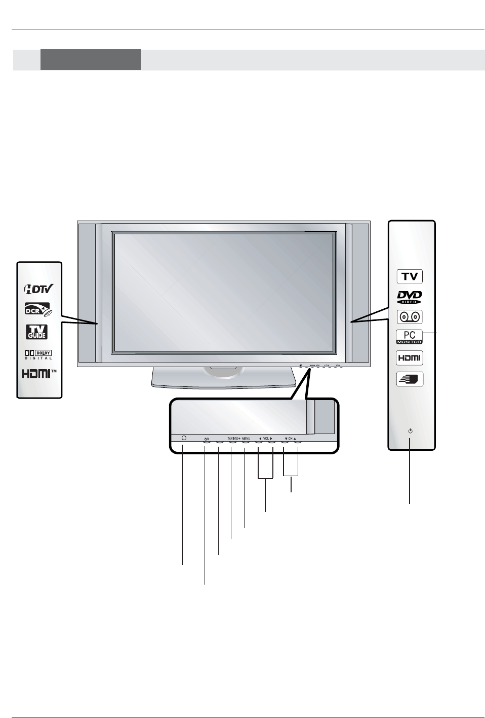
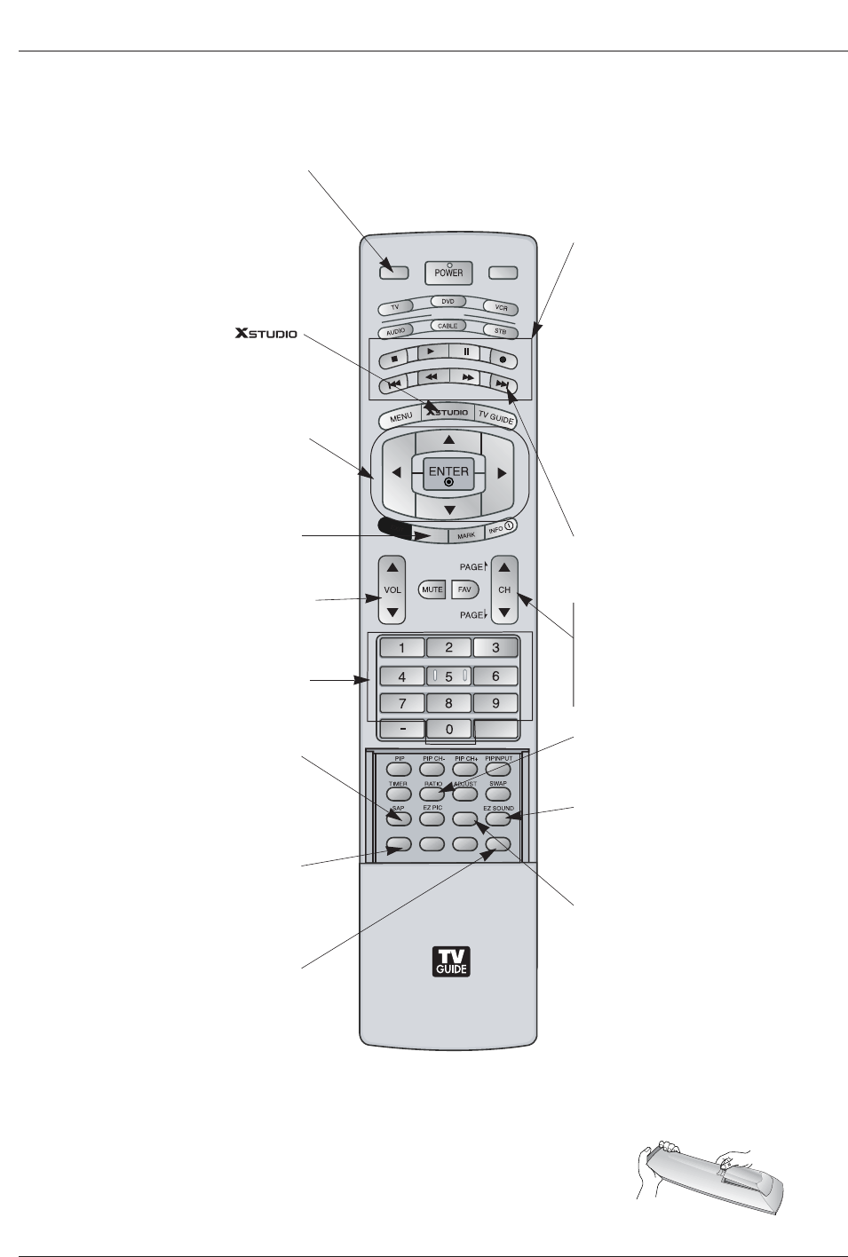
- This is a simplified representation of a front panel.
Here shown may be somewhat different from your TV.
MENU Button
TV/VIDEO Button
VOLUME (FF,G) Buttons
CHANNEL (E,D) Buttons
INDEX
Switches
LED Display
on or off.
TV GUIDE Button
Remote Control
Sensor
Power Standby Indicator
When the TV is turned on,
blinks orange in standby
mode, blinks green. And
after orange stop blinking,
you can directly turn on the
TV. But in case of green,
screen is displayed in 3~4
seconds later.
POWER Button
Controls
Controls
Front Panel Controls
Front Panel Controls
S-VIDEO
FRONT
A/V INPUT
VIDEO
L / MONO
AUDIO
R
RS-232C INPUT
(CONTROL/SERVICE)
AUDIO
R
L
DIGITAL AUDIO
(OPTICAL)
DVI
INPUT
COMPONENT2
INPUT
OUTPUT
AUDIO
INPUT
RGB INPUT
VIDEO
HDMI 2
HDMI1 /DVI
COMPONENT INPUT 1
R
L
(MONO)
CABLE
ANTENNA
AC INPUT
DVD
/DTV
INPUT
IEEE-1394
COMPONENT INPUT 2
MONITOR OUTPUT
A/V INPUT
VIDEO
AUDIO
S-VIDEO
REMOTE
CONTROL
Cable
Owner’s Manual 9
Introduction
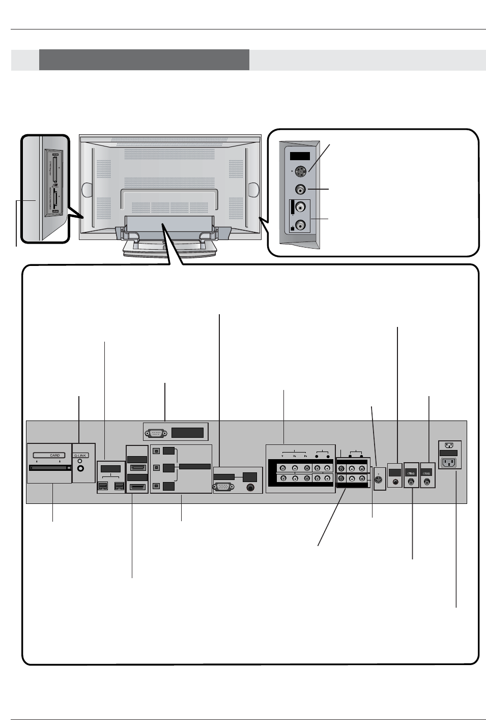
S-VIDEO Input
A connection is available to provide
better picture quality than the video
input.
Memory Card Slots
G-LINKTM
Connect an IR
controller to this
jack.
CableCARD™
Used for
CableCARD™
received from Cable
Service Provider.
VIDEO Input
Connects the video signal from a
video device.
AUDIO Input
Connections are available for listening
stereo sound from an external device.
Antenna Input
Connect over-the-
air signals to this
jack.
RGB/AUDIO INPUT
Connect the monitor output
from a PC to the appropriate
input port.
Digital Audio (DVI: Digital
Visual
Interface/Component2)
Input/
Digital Audio Output
Connect digital audio from
various types of equipment.
Note: In standby mode,
these ports will not work.
DVD/DTV Input
(Component 1-2)
Connect a component
video/audio device to
these jacks.
Monitor Output
Connect a second
TV or Monitor.
Remote Control Port
Connect your wired
remote control here.
S-Video Input
Connect S-
Video out from
an S-VIDEO
device to the S-
VIDEO input.
CABLE Input
Connect cable signals to this
jack, either directly or through
a cable box.
RS-232C INPUT (CON-
TROL/SERVICE) PORT
Connect to the RS-232C
port on a PC.
HDMI1/DVI, HDMI 2
Connect a HDMI sig-
nal to HDMI1/DVI or
HDMI2. Or connect a
DVI(Video) signal to
HDMI1/DVI.
Audio/Video Input
Connect audio/video
output from an
external device to
these jacks.
Power Cord Socket
This TV operates on an AC power. The voltage
is indicated on the Specifications page. Never
attempt to operate the TV on DC power.
IEEE1394
Connect a DVHS, a
MicroMV Camcorder, or
a set-top box to
IEEE1394 Connector.
Connection Options
Connection Options
Back Connection Panel
Back Connection Panel
Note:
- After removing the cover, you can insert the CableCARD™ or connect to the G-LINK jack.
10 Plasma TV
Installation
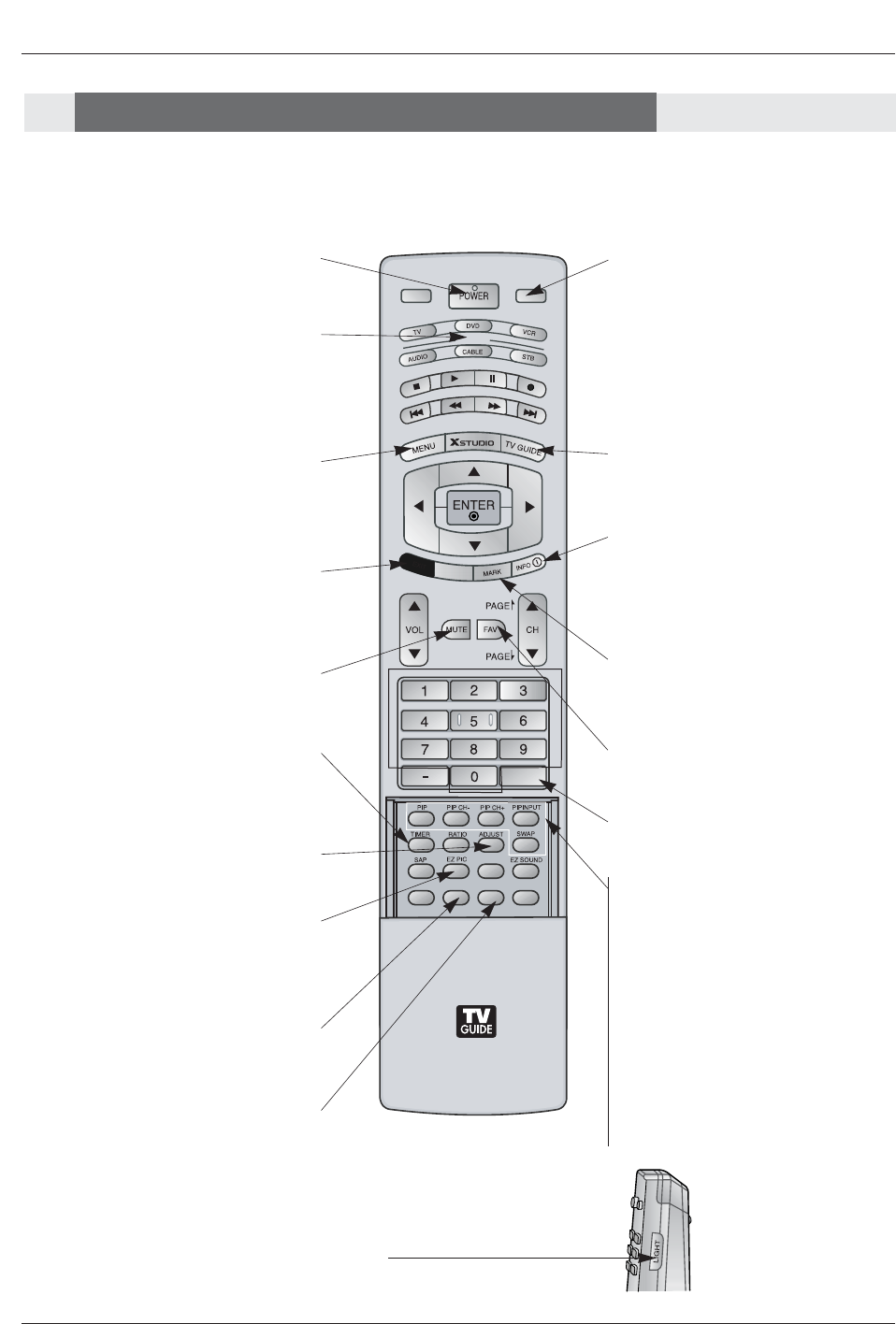
- When using the remote control, aim it at the remote control sensor on the TV.
MODE
DAY -
DAY +
FLASHBK
APM
CC
1394
FREEZE
TV INPUT TV/VIDEO
M/C EJECT
AUTO DEMO
EXIT
MUTE
Switches the sound on or off.
(Refer to p.86)
MODE
Selects the remote operating mode: TV,
DVD, VCR, AUDIO, CABLE or STB. Select
a mode other than TV, for the remote to
operate an external device.
FLASHBK
Tunes to the recent channels.
EXIT
Clears all on-screen displays and returns to
TV viewing from any menu.
TIMER
Lets you select the amount of time before
your TV turns itself off automatically.
MENU
Brings up the main menu to the screen.
Enters or exits a Panel Menu in the TV Guide
On Screen system.
PIP
Switches to PIP, POP (Picture-out-of-
Picture) and Twin picture modes in regu-
lar sequence.
Switches the video window locking or
unlocking in the Listings Grid.
PIPCH-/PIPCH+
Changes to the next higher/lower PIP
channel.
PIP INPUT
Selects the input source for the sub pic-
ture in PIP/Twin picture mode.
SWAP
Exchanges the main/sub images in
PIP/Twin picture mode.
EZ PIC
Selects a factory preset picture mode
depending on the viewing environment.
ADJUST
Adjusts screen position, size, and phase in
PC mode.
FREEZE
Freezes the currently-viewed picture. Main
picture is frozen in PIP/Twin picture mode.
TV/VIDEO
External input modes rotate in regular
sequence: Antenna, Cable, Video, Front
Video, Component 1-2, RGB-DTV (or
RGB-PC), HDMI1/DVI and HDMI2 input
sources.
(Video, Front Video, Component 1-2 input
sources are linked automatically, only if
these are connected )
POWER
Turns your TV or any other programmed
equipment on or off, depending on mode.
TV GUIDE
Brings up the TV Guide On Screen sys-
tem to the screen.
Mark
Selects a photo or music you want to
view or play in Xstudio mode.
LIGHT
Illuminates the remote control
buttons of selected mode.
INFO
Channel information is displayed on top of
the screen. But not available in
Component 1-2, RGB, HDMI1/DVI and
HDMI2 mode.(Refer to p.85)
FAV
Scrolls the Favorite channels.
AUTO DEMO
Starts the demonstration to explain the main
features of this TV.
Remote Control Key Functions
Remote Control Key Functions
Owner’s Manual 11
Installation
DAY+/DAY-
Moves forward or backward in 24 hour
increments in the Listings Grid.
MODE
DAY -
DAY +
FLASHBK
APM
CC
1394
FREEZE
TV INPUT TV/VIDEO
M/C EJECT
AUTO DEMO
EXIT
NUMBER buttons
VCR/DVD BUTTONS
• Controls some video cassette recorders
or DVD players. ("RECORD" button is not
available for DVD players.)
< Only TV mode >
•In Photo mode of Xstudio, the view state
changes to the slide show state with
“PLAY” button and the slide show state
changes to the view state with “PAUSE”
button.
• In Music mode of Xstudio, controls the
music with “PAUSE”, “STOP”, ”PLAY”,
”(Left/Right) SKIP” buttons. Note that FF
and REW do not work in the mode.
•Controls the DVHS or Camcorder of
IEEE 1394 mode.
RATIO
Changes the aspect ratio.
CC
Select a closed caption:
Off, CC1~4, Text1~4.
THUMBSTICK (Up/Down/Left/Right/ENTER)
Allows you to navigate the on-screen menus
and adjust the system settings to your pref-
erence.
CHANNEL UP/DOWN
Selects available channels found with
Manual scan.
PAGE UP/PAGE DOWN
Moves from one full set of screen infor-
mation to the next one.
SAP
Selects MTS sound: Mono, Stereo, and
SAP in Analog mode. Change the audio lan-
guage in DTV mode. EZ SOUND
Selects the sound appropriate for the
program's character.
APM (Adaptive Picture Mode)
Concurrently, compare with the
Daylight, Normal, Night Time and
Custom on the screen. (Refer to p.85)
VOLUME UP/DOWN
Increases/decreases the sound level.
1394 (Refer to p.33-37)
Brings up the menu to select the Photo or
Music mode of Xstudio for memory cards.
M/C EJECT
Remove the Memory
Card.
Installing Batteries
• Open the battery compartment cover on the back side and install the batteries
matching correct polarity (+ with +, - with -).
• Install two 1.5V AA batteries. Don’t mix old or used batteries with new ones.
Replace cover.
TV INPUT
• Rotates the input mode between Antenna
and Cable.
• Video, Front Video, Component 1-2,
RGB-DTV (or RGB-PC), HDMI1/DVI,
HDMI2
and IEEE1394 input sources, screen
returns to the last TV channel.
12 Plasma TV
Installation
Owner’s Manual
1.5V
1.5V
Batteries Power Cord
MODE
DAY-
DAY+
FLASHBK
APM
CC
AUTO DEMO
M/C EJECT
TV INPUT TV/VIDEO
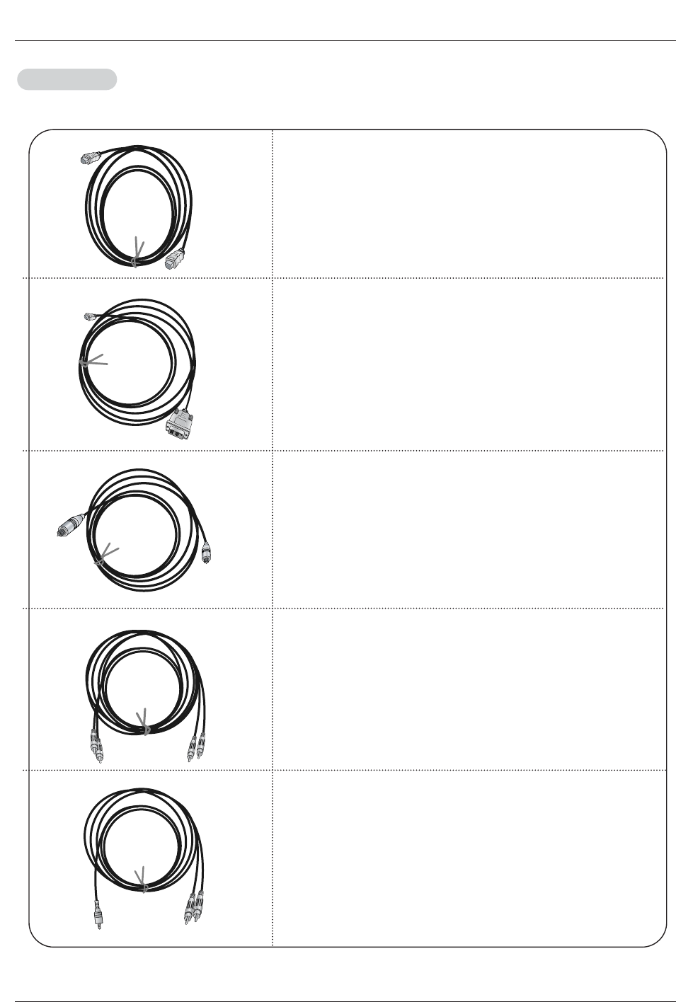
75ΩRound Cable
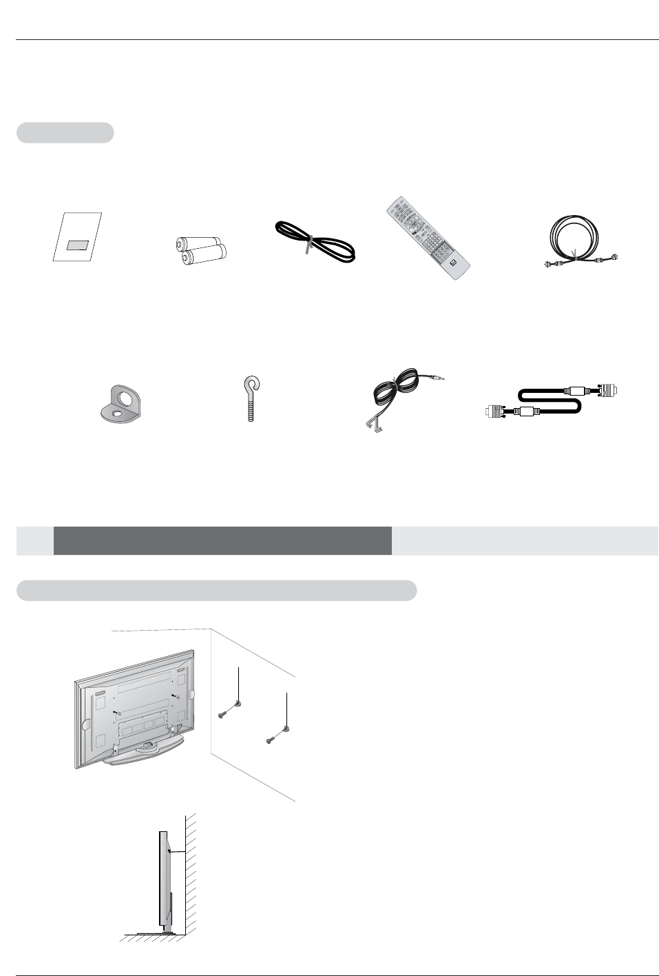
Ensure that the following accessories are included with your plasma display. If an accessory is missing, please contact the dealer
where you purchased the product.
• After the set must be mounted on the desk top, Insert
the 2 eye-bolts and tighten securely in the upper holes
as shown.
Install wall the brackets on the wall with 2 bolts*, (not
supplied with the product), as shown.
Match the height of the eye-bolts and the wall brack-
ets.
Check to be sure the eye-bolts or the brackets are
tightened securely.
• Secure the TV assembly to the wall with strong strings
or wire cables, (not supplied with the product), as
shown.
2-Wall brackets 2-eye-bolts G-LINK Cable
Remote Control
Installation
Installation
Accessories
Accessories
Installation Instructions
Installation Instructions
Joining the
Joining the TV assembly to the wall to protect the set tumbling
TV assembly to the wall to protect the set tumbling
D-sub 15 pin Cable
Owner’s Manual 13
Installation
Power
Supply
Short-circuit
Breaker
4 inches
4 inches
4 inches4 inches
2 inches
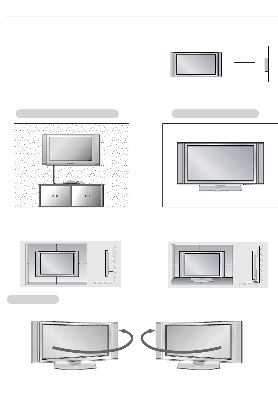
W
Wall Mount: Horizontal installation
all Mount: Horizontal installation
For proper ventilation, allow a clearance of 4” on each
side and 2” from the wall. Detailed installation instruc-
tions are available from your dealer, see the optional
Wall Mounting Bracket Installation.
4 inches
4 inches
2.36 inches
4 inches
2 inches
Desktop Pedestal Installation
Desktop Pedestal Installation
For proper ventilation, allow a clearance of 4” on each
side and the top, 2.36” on the bottom, and 2” from the
wall. Detailed installation instructions are included in
the optional Desktop Stand Installation.
GROUNDING
Ensure that you connect the grounding / earth wire to prevent possible
electric shock. If grounding methods are not possible, have a qualified
electrician install a separate circuit breaker. Do not try to ground the
unit by connecting it to telephone wires, lightening rods, or gas pipes.
• The TV can be installed in various ways such as on a wall, or on a desktop etc.
• The TV is designed to be mounted horizontally.
- Here shown may be somewhat different from your TV.
Swivel function
Swivel function
• After installing the TV, you can adjust the the TV set manually to the left or right direction by 20 degrees to suit your viewing
position.
Note: Before adjusting the angle, you must loosen (to the left) the shaft bolt on the middle of stand’s back.
And when stand be level with TV, you must close (to the right) the shaft bolt to set the hole.
- Swivel stand of 42PX4D/5D models is separately saled.
14 Plasma TV
Installation
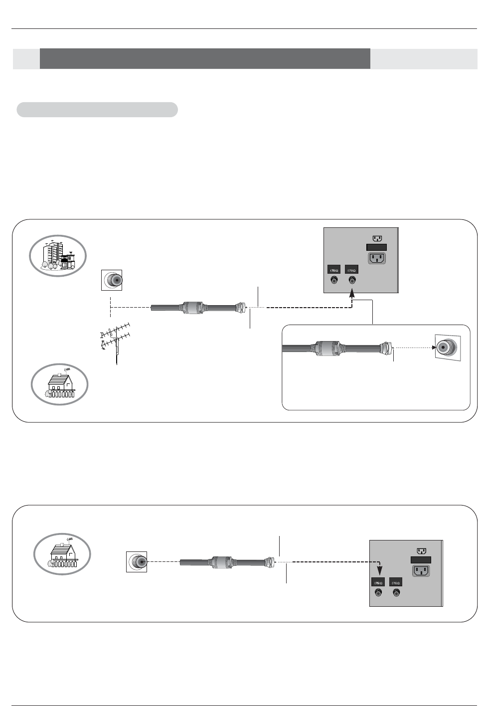
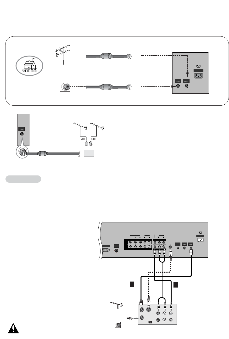
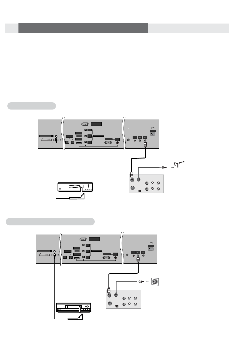
Antenna or Cable Connection
Antenna or Cable Connection
1. Analog and Digital TV signals provided on antenna
External Equipment Connections
External Equipment Connections
- Wall Antenna Socket or Outdoor Antenna without a Cable Box Connection
- For optimum picture quality, adjust antenna direction if needed.
2. Analog and Digital TV signals provided on cable
CABLE
ANTENNA
AC INPUT
Multi-family Dwellings/Apartments
(Connect to wall antenna socket)
Single-family Dwellings /Houses
(Connect to wall jack for outdoor antenna)
Outdoor
Antenna
Wall Antenna
Socket
VHF Antenna
UHF Antenna
RF Coaxial Wire (75 ohm)
Bronze Wire
Turn clockwise to tighten.
Bronze Wire
Be careful not to bend the bronze wire when
connecting the antenna.
Bronze Wire
Cable TV Wall
Jack RF Coaxial Wire (75 ohm)
CABLE
ANTENNA
AC INPUT
Turn clockwise to tighten.
Owner’s Manual 15
Installation
- To avoid picture noise (interference), leave an adequate distance between the VCR and TV
- Use the ISM Method (on the Option menu) feature to avoid having a fixed image remain on the screen for a long period of time.
If the 4:3 picture format is used; the fixed images on the sides of the screen may remain visible on the screen.
Connection Option 1
Set VCR output switch to channel 3 or 4 and
then tune the TV to the same channel number.
Connection Option 2
1. Connect the audio and video cables from the
VCR's output jacks to the TV input jacks, as
shown in the figure.
When connecting the TV to VCR, match the
jack colors (Video = yellow, Audio Left = white,
and Audio Right = red).
If you connect an S-VIDEO output from VCR to
the S-VIDEO input, the picture quality is
improved; compared to connecting a regular
VCR to the Video input.
2. Insert a video tape into the VCR and press
PLAY on the VCR. (Refer to the VCR owner’s
manual.)
3. Select the input source with using the
TV/VIDEO button on the remote control. Note
that this TV finds the connected input sources
automatically for Video, Front Video and
Component 1-2. It is presumed that RGB,
HDMI1/DVI and HDMI2 sources are connected.
Do not connect to both Video and
S-Video at the same time.
VCR Setup
VCR Setup
UT
CE)
AUDIO
R
L
(OPTICAL)
RGB INPUT
VIDEO
COMPONENT INPUT 1
R
L
(MONO)
CABLE
ANTENNA
AC INPUT
DVD
/DTV
INPUT
COMPONENT INPUT 2
MONITOR OUTPUT
A/V INPUT
VIDEO
AUDIO
S-VIDEO OUT
IN
(R) AUDIO (L) VIDEO
34
OUTPUT
SWITCH
ANT OUT
ANT IN
AUDIO
INPUT
S-VIDEO
REMOTE
CONTROL
VCR Rear
12
• To improve the picture quality in a poor signal area,
please purchase a signal amplifier and install properly.
• If the antenna needs to be split for two TV’s, install a “2-
Way Signal Splitter” in the connections.
• If the antenna is not installed properly, contact your deal-
er for assistance.
ANTENNA
Signal
Amplifier
3. Analog and Digital TV signals provided on cable and antenna
Antenna
RF Coaxial Wire (75 ohm)
Bronze Wire
Turn clockwise to tighten.
Cable TV Wall
Jack RF Coaxial Wire (75 ohm)
CABLE
ANTENNA
AC INPUT
Bronze Wire
16 Plasma TV
Installation
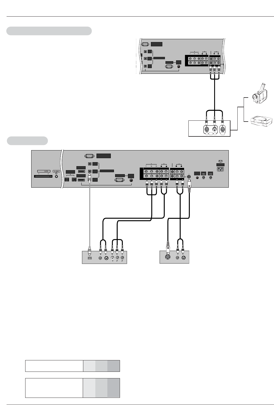
•Component Input ports
To get better picture quality, connect a DVD player to the compo-
nent input ports as shown below.
How to connect
Connect the audio and video cables from the external equip-
ment's output jacks to the TV input jacks, as shown in the
figure.
When connecting the TV to external equipment, match the
jack colors (Video = yellow, Audio Left = white, and Audio
Right = red).
How to use
1. Select the input source with using the TV/VIDEO button on
the remote control. Note that this TV finds the connected
input sources automatically for Video, Front Video and
Component 1-2. It is presumed that RGB, HDMI1/DVI and
HDMI2 sources are connected.
2. Operate the corresponding external equipment. For connec-
tion instructions to operate the TV Guide On Screen system,
see page 24.
Component ports
on the TV YPBPR
Video output ports
on DVD player
Y
Y
Y
Y
Pb
B-Y
Cb
PB
Pr
R-Y
Cr
PR
How to connect
1. Connect the DVD video outputs (Y, PB, PR) to the COMPONENT (Y, PB, PR) INPUT jacks on the TV and connect the DVD
audio outputs to the AUDIO INPUT jacks on the TV, as shown in the figure.
2. If your DVD only has an S-Video output jack, connect this to the S-VIDEO input on the TV and connect the DVD audio outputs
to the AUDIO INPUT jacks on the TV, as shown in the figure.
Note: If your DVD player does not provide component video output, use S-Video output.
How to use
1. Turn on the DVD player and then insert a DVD.
2. Use the TV/VIDEO button on the remote control to select Component 1 or Component 2. (If connected to S-VIDEO, select
the Video or Front Video external input source.)
3. Refer to the DVD player's manual for operating instructions.
External
External A/V Source Setup
A/V Source Setup
DVD Setup
DVD Setup
RS-232C INPUT
(CONTROL/SERVICE)
AUDIO
R
L
DIGITAL AUDIO
(OPTICAL)
DVI
INPUT
COMPONENT2
INPUT
OUTPUT
RGB INPUT
VIDEO
HDMI 2
HDMI /DVI
COMPONENT INPUT 1
R
L
(MONO)
V
I
D
E
O
S
R
E
M
O
T
E
C
O
N
T
R
O
L
CABLE
ANTENNA
AC INPUT
DVD
/DTV
INPUT
COMPONENT INPUT 2
MONITOR OUTPUT
A/V INPUT
VIDEO
AUDIO
RL
AUDIO VIDEO
AUDIO
INPUT
RS-232C INPUT
(CONTROL/SERVICE)
AUDIO
R
L
DIGITAL AUDIO
(OPTICAL)
DVI
INPUT
COMPONENT2
INPUT
OUTPUT
RGB INPUT
VIDEO
HDMI 2
HDMI1 /DVI
COMPONENT INPUT 1
R
L
(MONO)
CABLE
ANTENNA
AC INPUT
DVD
/DTV
INPUT
IEEE-1394
COMPONENT INPUT 2
MONITOR OUTPUT
A/V INPUT
VIDEO
AUDIO
BR
(R) AUDIO (L)
DIGITAL AUDIO
OPTICAL
(R) AUDIO (L)
S-VIDEO
AUDIO
INPUT
S-VIDEO
REMOTE
CONTROL
Cable
DVD
or
Camcorder
Video Game
Device
Notes:
• Digital Audio will not work for Component 1 input source.
• Digital Audio operation has priority if Digital Audio and AUDIO L/R
are connected at the same time.
or
Owner’s Manual 17
Installation
- This TV can receive Digital Over-the-air/Cable signals without an external digital set-top box. However, if you do receive Digital
signals from a digital set-top box or other digital external device, refer to the figure as shown below.
- This TV supports HDCP (High-bandwidth Digital Contents Protection) protocol for Digital Contents (480p,720p,1080i).
How to connect
Use the TV’s COMPONENT (Y, PB, PR) INPUT, RGB, HDMI1/DVI or
HDMI2 jack for video connections, depending on your set-top box con-
nector. Then, make the corresponding audio connections.
How to use
1. Turn on the digital set-top box. (Refer to the owner’s manual for the
digital set-top box.)
2. Use TV/VIDEO on the remote control to select Component 1,
Component 2,RGB-DTV, or HDMI1/DVI,HDMI2 source.
HDSTB Setup
HDSTB Setup
RS-232C INPUT
(CONTROL/SERVICE)
AUDIO
R
L
DIGITAL AUDIO
(OPTICAL)
DVI
INPUT
COMPONENT2
INPUT
OUTPUT
RGB INPUT
VIDEO
HDMI 2
HDMI1 /DVI
COMPONENT INPUT 1
R
L
(MONO)
CABLE
ANTENNA
AC INPUT
DVD
/DTV
INPUT
IEEE-1394
COMPONENT INPUT 2
MONITOR OUTPUT
A/V INPUT
VIDEO
AUDIO
Cable
(R) AUDIO (L)
RGB-DTV OUTPUT
BR
(R) AUDIO (L)
DIGITAL AUDIO
OPTICAL
(R) AUDIO (L)
DVI-DTV OUTPUT
DIGITAL AUDIO
OPTICAL
HDMI-DTV OUTPUT
AUDIO
INPUT
S-VIDEO
REMOTE
CONTROL
Digital Set-top Box
or
or
or
or
Signal
480i
480p
720p
1080i
Component 1/2
Yes
Yes
Yes
Yes
RGB-DTV,HDMI1/DVI,HDMI2
No
Yes
Yes
Yes
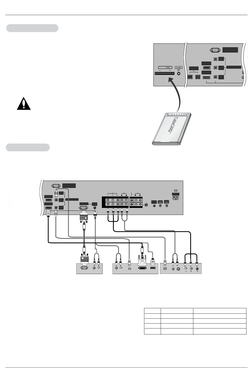
CableCARD
CableCARDTM
TM Setup
Setup
RS-232C INPUT
(CONTROL/SERVICE)
DIGITAL AUDIO
(OPTICAL)
DVI
INPUT
COMPONENT2
INPUT
OUTPUT
RGB IN
HDMI 2
HDMI1 /DVI
IEEE-1394
Cable
How to use
Insert the CableCARDTM
TM received from the cable service provider to
the CableCARDTM
TM slot of TV back panel.
If the pairing information about this TV and the CableCARD is auto-
matically displayed on the screen, contact with the cable service
provider.
Note :
• CableCARDTM
TM have the types of Motorola, Scientific Atlanta, SCM etc..
These 3 types of CableCARDTM
TM can be used for this PLASMA TV.
Caution: When removing the CableCARDTM
TM, do not
drop it as this may cause damage to the
CableCARDTM
TM.
or

18 Plasma TV
<When the PC supports DVI>
How to connect
1. Connect the PC to HDMI1/DVI port of this TV with an HDMI-to-DVI cable(not supplied with this product).
If you do not need to connect audio, HDMI2 port is also available for the DVI video connection.
2. If the PC(or the sound card of the PC) has a fiber optic digital audio output connector, connect the PC's audio output to DIGI-
TAL AUDIO(OPTICAL) port for DVI INPUT.
3. If the PC(or the sound card of the PC) has an analog audio output connector, connect the PC's audio output to AUDIO INPUT
port located on the right side of RGB INPUT port.
How To Use
1. To get the best picture quality, adjust the PC graphics card to 1024x768, 60Hz.
2. Select HDMI1/DVI input source in main input option of SETUP menu.(Refer to P.61)
TV/VIDEO button is also available for this purpose.
3. Check the image on your TV. There may be noise associated with the resolution, vertical pattern, contrast or brightness in PC
mode. If noise is present, change the PC output to another resolution, change the refresh rate to another rate or adjust the
brightness and contrast on the VIDEO menu until the picture is clear. If the refresh rate of the PC graphic card can not be
changed, change the PC graphic card or consult the manufacturer of the PC graphic card.
<When the PC supports RGB>
How to connect
1. Connect the PC to RGB INPUT port of this TV with a RGB cable(not supplied with this product).
2. If the PC(or the sound card of the PC) has an analog audio output connector, connect the PC's audio output to AUDIO INPUT
port located on the right side of RGB INPUT port.
How To Use
1. To get the best picture quality, adjust the PC graphics card to 1024x768, 60 Hz.
2. Select RGB-PC input source in main input option of SETUP menu.(Refer to P.61)
Once you select RGB-PC in main input option of SETUP menu, TV/VIDEO button is also available for this purpose.
3. Check the image on your TV. There may be noise associated with the resolution, vertical pattern, contrast or brightness in PC
mode. If noise is present, change the PC output to another resolution, change the refresh rate to another rate or adjust the
brightness and contrast on the VIDEO menu until the picture is clear. If the refresh rate of the PC graphic card can not be
changed, change the PC graphic card or consult the manufacturer of the PC graphic card.
720x400
Installation
PC Setup
PC Setup
- This TV provides Plug and Play capability, meaning that the PC adjusts automatically to the TV's settings.
- The TV perceives 640x480, 60Hz as DTV 480p based on the PC graphic card, change the screen scanning rate for the graphic
card accordingly.
800x600
70.08
85.03
59.94
72.80
75.00
85.00
35.156
37.879
48.077
46.875
53.674
48.363
56.476
60.023
56.25
60.31
72.18
75.00
85.06
60.00
70.06
75.02
Vertical
Frequency(Hz) Resolution Horizontal
Frequency(KHz)
Vertical
Frequency(Hz)
1024x768
Resolution
640x480
Horizontal
Frequency(KHz)
31.469
37.927
31.469
37.861
37.500
43.269
Monitor Display Specifications (RGB-PC )
Owner’s Manual 19
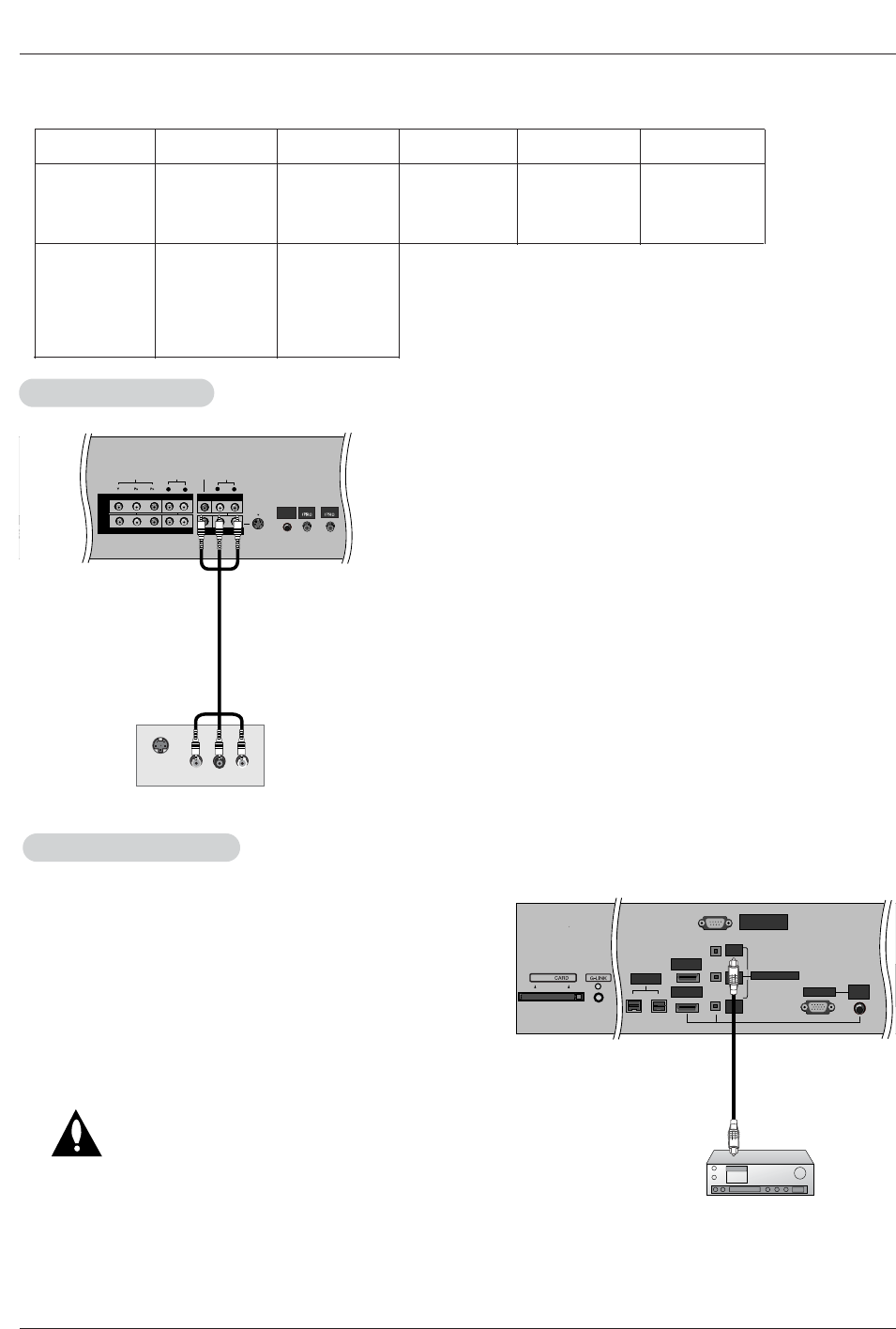
Installation
Send the TV’s audio to external audio equipment (stereo system) via
the Digital Audio Output (Optical) port.
How to connect
1. Connect one end of an optical cable to the TV Digital Audio
(Optical) Output port.
2. Connect the other end of the optical cable to the digital audio (opti-
cal) input on the audio equipment.
See the external audio equipment instruction manual for operation.
Caution: Do not look into the optical output port.
Looking at the laser beam may damage
your vision.
Digital
Digital Audio Output
Audio Output
RS-232C INPUT
(CONTROL/SERVICE)
DIGITAL AUDIO
(OPTICAL)
DVI
INPUT
COMPONENT2
INPUT
OUTPUT
RGB INPUT
HDMI 2
HDMI1 /DVI
DVD
/DTV
INPU
IEEE-1394
AUDIO
INPUT
Cable
The TV has a special signal output capability which allows you to
hook up the second TV or monitor.
Connect the second TV or monitor to the TV’s MONITOR OUTPUT.
See the Operating Manual of the second TV or monitor for further
details regarding the device’s input settings.
Note
•Component 1-2, RGB-PC/RGB-DTV, HDMI1/DVI,HDMI2, DTV
input sources cannot be used for Monitor out.
AUDIO
R
L
AUDIO INPUT
RGB INPUT
VIDEO
COMPONENT INPUT 1
R
L
(MONO)
CABLE
ANTENNA
AC INPUT
DVD
/DTV
INPUT
COMPONENT INPUT 2
MONITOR OUTPUT
A/V INPUT
VIDEO
AUDIO
S-VIDEO IN
(L) AUDIO (R)
VIDEO
S-VIDEO
REMOTE
CONTROL
Monitor Out Setup
Monitor Out Setup
Resolution
640x480
800x600
Horizontal
Frequency(KHz)
31.469
37.861
37.500
35.156
37.879
48.077
46.875
59.94
72.80
75.00
56.25
60.31
72.18
75.00
48.363
56.476
60.023
60.00
70.06
75.02
Vertical
Frequency(Hz) Resolution Horizontal
Frequency(KHz)
Vertical
Frequency(Hz)
1024x768
Monitor Display Specifications (HDMI/DVI Mode)

20 Plasma TV
Installation
- HDMITM, the HDMI logo and High-Definition Multimedia Interface is a trademark or registered trademark of HDMI Licensing.
- This TV can receive the High-Definition Multimedia Interface(HDMI) or the Digital Visual Interface(DVI).
- This TV supports HDCP(High-bandwidth Digital Contents Protection) Protocol for 720x480p, 1280x720p, and 1920x1080i resolu-
tion.
- When you connect this TV with a source device(DVD player, Set Top Box or PC) supporting Auto HDMI/DVI function, the output
resolution of the source device will be automatically set to 1280x720p.
- If the source device does not support Auto HDMI/DVI, you need to set the output resolution appropriately.
To get the best picture quality, adjust the DVD Player or Set Top Box's output resolution to 1280x720p, and the PC graphics card's
output resolution to 1024x768, 60Hz.
- If the source device has an HDMI output, no other audio connection is necessary because HDMI-to-HDMI connection includes
both video and audio.
- If the source device has a DVI output and no HDMI output, a separated audio connection is necessary.
<When the source device(DVD player or Set Top Box) supports HDMI>
How To Connect
1. Connect the source device to HDMI1/DVI or HDMI2 port of this TV with an HDMI cable(not supplied with this product).
2. No separated audio connection is necessary.
How To Use
- If the source device supports Auto HDMI function, the output resolution of the source device will be automatically set to 1280x720p.
- If the source device does not support Auto HDMI, you need to set the output resolution appropriately.
To get the best picture quality, adjust the output resolution of the source device to 1280x720p.
- Select HDMI1/DVI or HDMI2 input source in main input option on the SETUP menu.(Refer to P.61)
TV/VIDEO button is also available for this purpose.
<When the source device(DVD player or Set Top Box) supports DVI>
How To Connect
1. Connect the source device to HDMI1/DVI port of this TV with a HDMI-to-DVI cable(not supplied with this product).
Do not use HDMI2 port for DVI connection if you want to connect audio.
2. A separated audio connection is necessary.
3. If the source device has a fiber optic digital audio output, connect the audio output to DIGITAL AUDIO(OPTICAL) port for DVI
INPUT.
4. , connect the PC's audio output to AUDIO INPUT port located on the right side of RGB INPUT port.
How To Use
- If the source device supports Auto DVI function, the output resolution of the source device will be automatically set to 1280x720p.
- If the source device does not support Auto DVI, you need to set the output resolution appropriately.
To get the best picture quality, adjust the output resolution of the source device to 1280x720p.
- Select HDMI1/DVI input source in main input option on the SETUP menu.(Refer to P.61)
TV/VIDEO button is also available for this purpose.
HDMI
HDMI
Owner’s Manual 21
Installation
Cable sample
HDMI Cable
(not supplied with the product)
HDMI to DVI Cable
(not supplied with the product)
Fiber Optic Digital Audio Cable
(not supplied with the product)
Analog Audio Cable(RCA type)
(not supplied with the product)
Analog Audio Cable(Stereo to RCA type)
(not supplied with the product)
Reference
Reference
22 Plasma TV
Installation
How to use
1. Connect the HDMI1/DVI Source Devices(DVD Player or Set Top Box or PC) and the TV SET.
2. Turn on the display by pressing the POWER button on the TV SET and HDMI1/DVI Source Devices remote control.
3. Select HDM1/DVI Input source in Main Input option on the SETUP menu.(Refer to P.61)
4. Check the image on your TV SET. There may be noise associated with the resolution, vertical pattern, contrast or brightness in
HDMI1/DVI Source Devices. If noise is present, change the HDMI1/DVI Source Devices to another resolution, change the
refresh rate or adjust the brightness and contrast on the menu until the picture is clear. If the refresh rate of the PC graphics
card can not changed, change the PC graphics card or consult the manufacturer of the PC graphics card.
Notes:
- Depending on the graphics card, DOS mode may not work if a HDMI to DVI Cable is in use.
- Avoid keeping a fixed image on the screen for a long period of time. The fixed image may become permanently imprinted on the
screen. Use the Orbiter feature on the ISM Method menu.
- When Source Devices connected with HDMI1/DVI Input, output PC Resolution(VGA, SVGA, XGA), Position and Size may not fit
to Screen. As shown the picture below, press the ADJUST button to adjust the screen Position of TV SET and contact an PC
graphics card service center.
- When Source Devices connected with HDMI1/DVI Input, output TV SET Resolution(480p, 720p, 1080i) and TV SET Display fit
EIA/CEA-861-B Specification to Screen. If not, refer to the Manual of HDMI1/DVI Source Devices or contact your service cen-
ter.
- In case HDMI1/DVI Source Devices is not connected Cable or poor cable connection, "NO SIGNAL" OSD display in HDMI1/DVI
Input. In case that Video Resolution is not supported TV SET output in HDMI1/DVI Source Devices, "INVALID FORMAT" OSD
display. Refer to the Manual of HDMI1/DVI Source Devices or contact your service center.
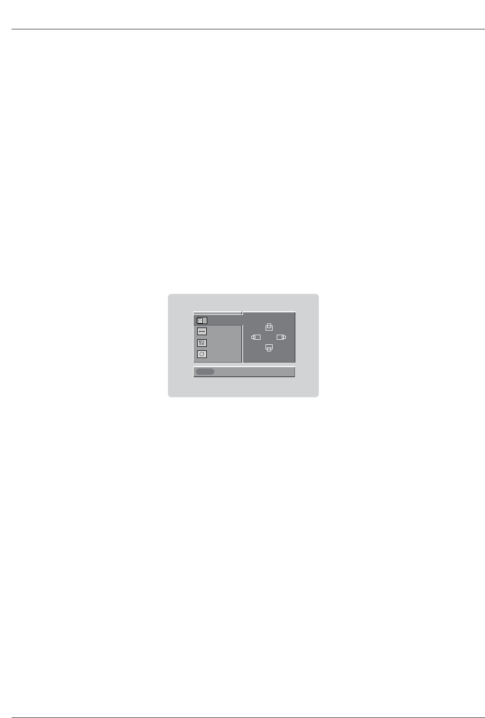
Close
POSITION G
SIZE
PHASE
RESET
Adjust
D
FG
E
In This Mode, the Supported TV SET Resolution Specification
- 1920 x 1080 I @ 59.94Hz / 60Hz, 16:9
- 1280 x 720 P @ 59.94Hz / 60Hz, 16:9(preferred format)
- 720 x 480 P @ 59.94Hz / 60Hz, 16:9
- 720 x 480 P @ 59.94Hz / 60Hz, 4:3
In This Mode, the Supported PC Resolution Specification
- 640 x 480 @ 60Hz
- 640 x 480 @ 72Hz
- 640 x 480 @ 75Hz
- 800 x 600 @ 56Hz
- 800 x 600 @ 60Hz
- 800 x 600 @ 72Hz
- 800 x 600 @ 75Hz
- 1024 x 768 @ 60Hz(preferred format)
- 1024 x 768 @ 70Hz
- 1024 x 768 @ 75Hz
PC mode
Owner’s Manual 23
Installation
- The TV Guide On Screen system uses Setup information to provide you with show listings and lineups in your area—which are
updated several times a day.
- Once you set up the TV according to manufacturer’s instructions, you are ready to set up the TV Guide On Screen system.
- To download program listings the TV Guide On Screen system needs to be able to change channels on your cable box when
the TV is not in use. Please connect the supplied G-LINK cable to the G-LINK jack of the TV. After you connect the G-LINK
cable you will be able to control your cable box using the TV’s remote.
Note:The TV Guide On Screen system interactive program guide provides listings for cable-ready, cable box, and digital cable
services as well as over-the-air broadcast. It does not provide listings for satellite services.
RS-232C INPUT
(CONTROL/SERVICE)
DIGITAL AUDIO
(OPTICAL)
DVI
INPUT
COMPONENT2
INPUT
OUTPUT
RGB INPUT
HDMI 2
HDMI /DVI
CABLE
ANTENNA
AC INPUT
IEEE-1394
Cable
S-VIDEO
OUT
IN
(R) AUDIO (L) VIDEO
34
OUTPUT
SWITCH
ANT IN
ANT OUT
AUDIO
INPUT
S-VIDEO
REMOTE
CONTROL
RS-232C INPUT
(CONTROL/SERVICE)
DIGITAL AUDIO
(OPTICAL)
DVI
INPUT
COMPONENT2
INPUT
OUTPUT
RGB INPUT
HDMI 2
HDMI /DVI
CABLE
ANTENNA
AC INPUT
IEEE-1394
Cable
S-VIDEO
OUT
IN
(R) AUDIO (L) VIDEO
34
OUTPUT
SWITCH
ANT IN
ANT OUT
S-VIDEO
REMOTE
CONTROL
AUDIO
INPUT
VCR Rear
VCR Front
VCR Rear
VCR Front
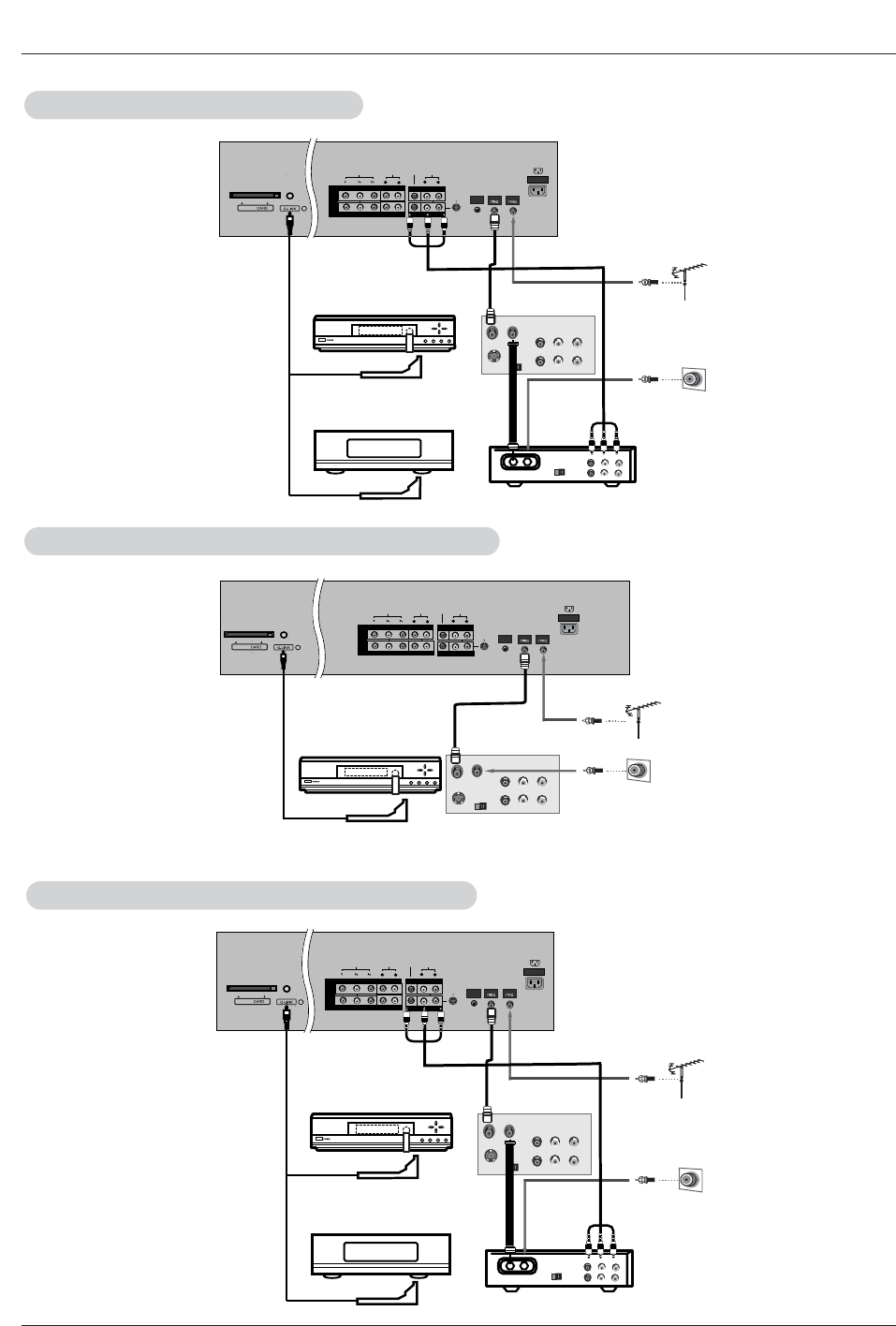
TV Guide On Screen Setup
TV Guide On Screen Setup
Antenna Service
Antenna Service
How to connect VCR and Cable Box
Cable Service without a Cable Box
Cable Service without a Cable Box
24 Plasma TV
Installation
AUDIO
R
L
VIDEO
COMPONENT INPUT 1
R
L
(MONO)
CABLE
ANTENNA
AC INPUT
DVD
/DTV
INPUT
COMPONENT INPUT 2
MONITOR OUTPUT
A/V INPUT 1
VIDEO
AUDIO
Cable
S-VIDEO
OUT
IN
(R) AUDIO (L) VIDEO
34
OUTPUT
SWITCH
RF
TV
VCR
Cable
(R) AUDIO (L) VIDEO
34
OUTPUT
SWITCH
ANT OUT
ANT IN
S-VIDEO
REMOTE
CONTROL
AUDIO
R
L
VIDEO
COMPONENT INPUT 1
R
L
(MONO)
CABLE
ANTENNA
AC INPUT
DVD
/DTV
INPUT
COMPONENT INPUT 2
MONITOR OUTPUT
A/V INPUT 1
VIDEO
AUDIO
Cable
S-VIDEO
OUT
IN
(R) AUDIO (L) VIDEO
34
OUTPUT
SWITCH
ANT IN
ANT OUT
S-VIDEO
REMOTE
CONTROL
AUDIO
R
L
VIDEO
COMPONENT INPUT 1
R
L
(MONO)
CABLE
ANTENNA
AC INPUT
DVD
/DTV
INPUT
COMPONENT INPUT 2
MONITOR OUTPUT
A/V INPUT 1
VIDEO
AUDIO
Cable
S-VIDEO
OUT
IN
(R) AUDIO (L) VIDEO
34
OUTPUT
SWITCH
RF
TV
VCR
Cable
(R) AUDIO (L) VIDEO
34
OUTPUT
SWITCH
ANT OUT
ANT IN
S-VIDEO
REMOTE
CONTROL
Cable Box Rear
VCR Rear
VCR Front
Cable Box Front
or
VCR Rear
VCR Front
Cable Box Rear
VCR Rear
VCR Front
Cable Box Front
or
Cable Service with a Cable Box
Cable Service with a Cable Box
Antenna and Cable Service without a Cable Box
Antenna and Cable Service without a Cable Box
Antenna and Cable Service with a Cable Box
Antenna and Cable Service with a Cable Box
Owner’s Manual 25
Installation
Note:
• The G-LINKTM cable is necessary for the TV Guide On Screen system to work with your Cable Box and VCR. See Page
23~24 for G-LINKTM connection instructions.
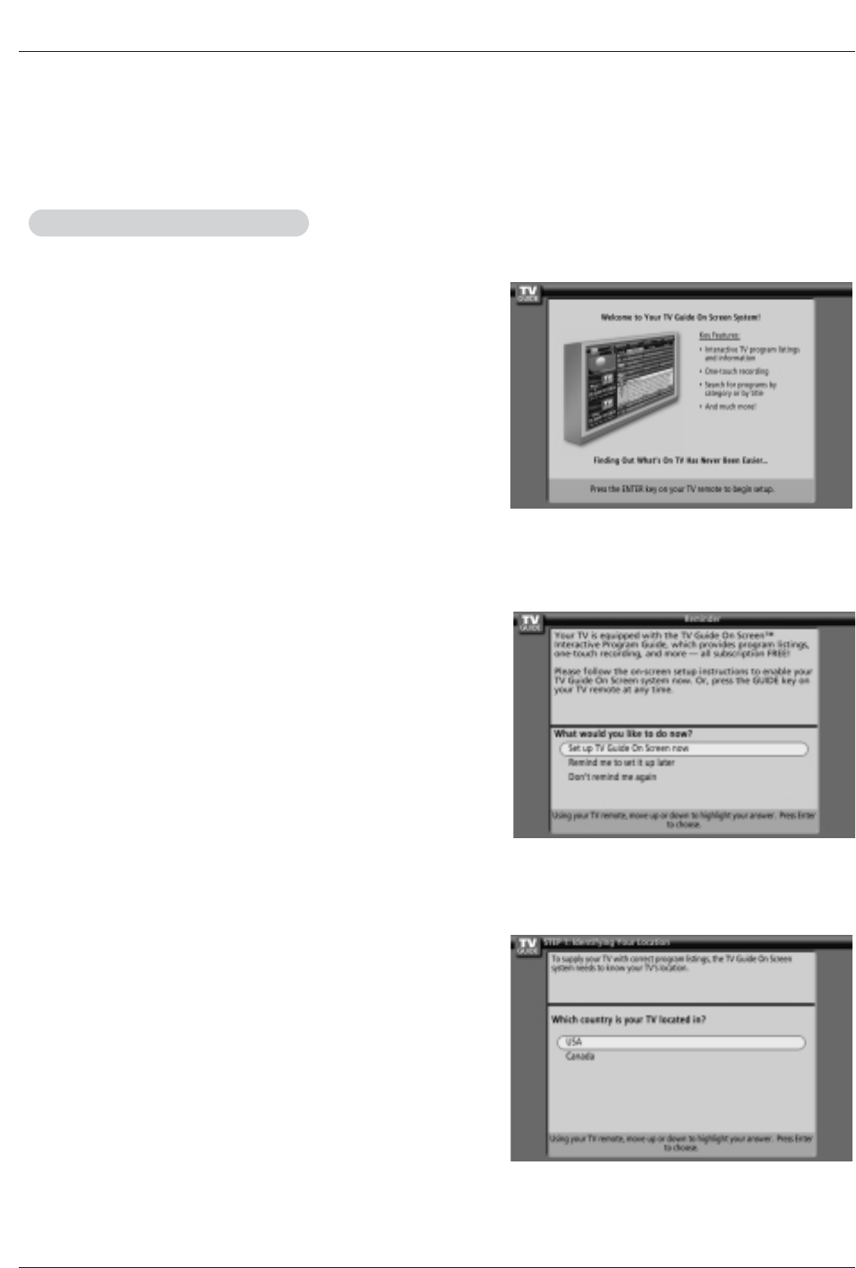
The TV Guide On Screen system's Welcome Screen appears:
-- by pressing the TV Guide key
-- when you power On your TV if you previously skipped "Set up TV
Guide On Screen now" on the Reminder Screen.
The Welcome Screen highlights features of the TV Guide On Screen
system.
Press ENTER to begin Setup.
How to use
1. Screen 1: Country
• This screen asks you the location of your TV.
• Use the D/Ebutton to highlight a country.
• Press ENTER to display Screen 2.
The TV Guide On Screen system's Reminder Screen appears:
-- after initial TV set up
-- if you power Off the TV and then power it back On
To make a selection, use the D/Ebutton to highlight to an option,
and press ENTER.
• "Set up TV Guide On Screen now," displays the Welcome Screen.
Press ENTER to begin Setup.
• "Remind me to set up later" returns you to watching TV.
• "Don't remind me again" returns you to watching TV and stops the
reminder screen from appearing upon power On.
2.Reminder Screen
1.Welcome Screen
TV Guide On Screen Setup
TV Guide On Screen Setup
26 Plasma TV
Installation
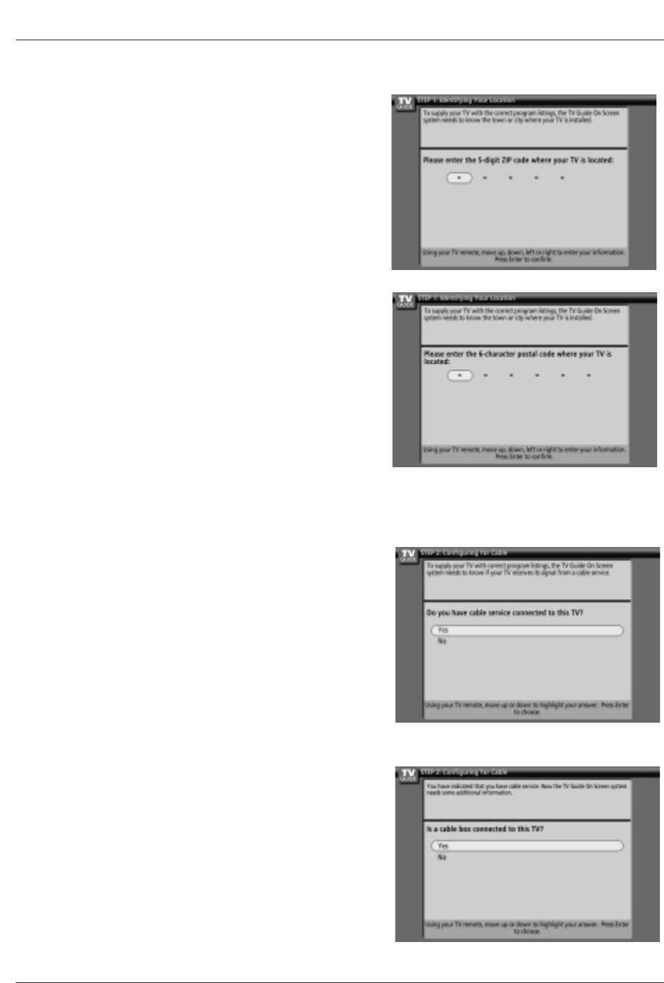
2. Screen 2: Enter Zip or Postal Code
Option 1
• If you selected USA in Screen 1, you see the ZIP Code screen.
• You input numbers by either pressing the number keys on the remote
or using the D/Ebutton to display a number, and then the F/Gbut-
ton to move to another field.
• Press ENTER to display Screen 3.
Option 2
• If you selected Canada in Screen 1, you see the Postal Code screen.
• You input characters by using the D/Ebutton, and then the F/G
button to move to another field.
• Press ENTER to display Screen 3.
3. Screen 3: Do you have Cable Service connected?
• If you select Yes, you see Screen 4.
• If you select No, you see Screen 12.
4. Screen 4: Do you have a Cable Box?
• If you select Yes, you see Screen 5.
• If you select No, you see Screen 12.
Owner’s Manual 27
Installation
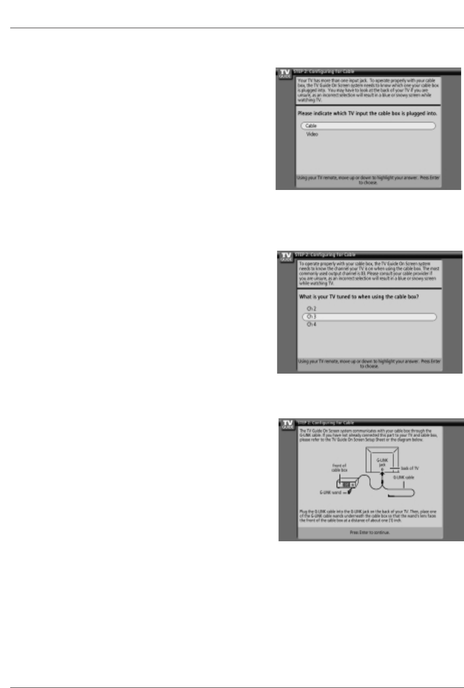
6. Screen 6: Cable Box Tuning Channel
• Select the channel used for the cable box.
• Press ENTER to display Screen 7.
7. Screen 7: Cable Box Configuration Diagram
• The diagram shows the correct way to install the G-LINK Cable from
the back of the device to the cable box.
Make sure the G-LINKTM Cable is properly installed.
• Press ENTER to display Screen 8.
5. Screen 5: Which TV input is the cable box plugged into?
• If you select Cable, you see Screen 6.
• If you make any other choice, you see Screen 7 .
28 Plasma TV
Installation
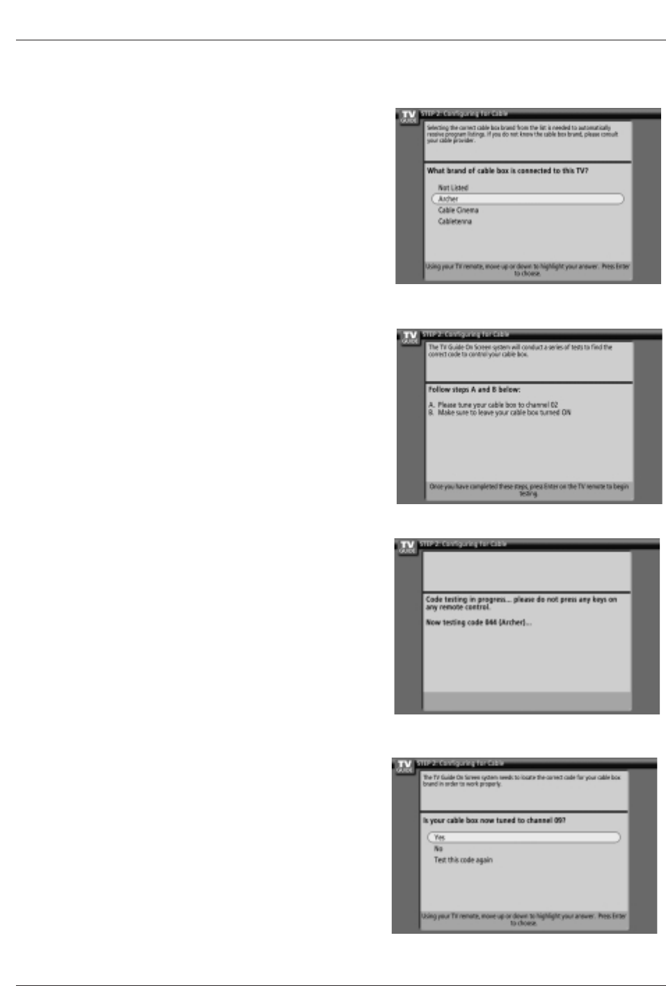
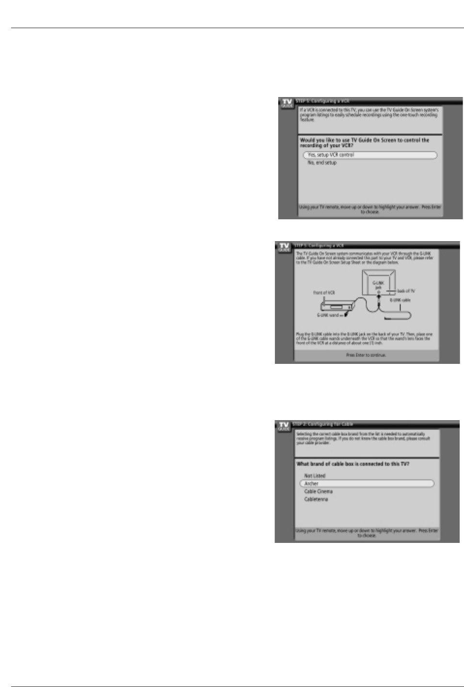
8. Screen 8: Cable Box Brand Name
• Use the D/Ebutton to select a cable box brand.
• Press ENTER to display Screen 9.
9. Screen 9: Cable Box Preparation
• Follow the on-screen instructions, and press ENTER to display
Screen 10.
10. Screen 10: Cable Box Code Testing
• When testing is done, Screen 11 displays automatically.
11. Screen 11: Cable Box Tuned to Channel 9?
• If you select Yes, you see Screen 12.
• If you select No, a different code is tested in Screen 10.
Note:
• Many Cable Boxes require testing more than one code.
• If you select Test this code again, the same code is tested again
in Screen 10.
Owner’s Manual 29
Installation
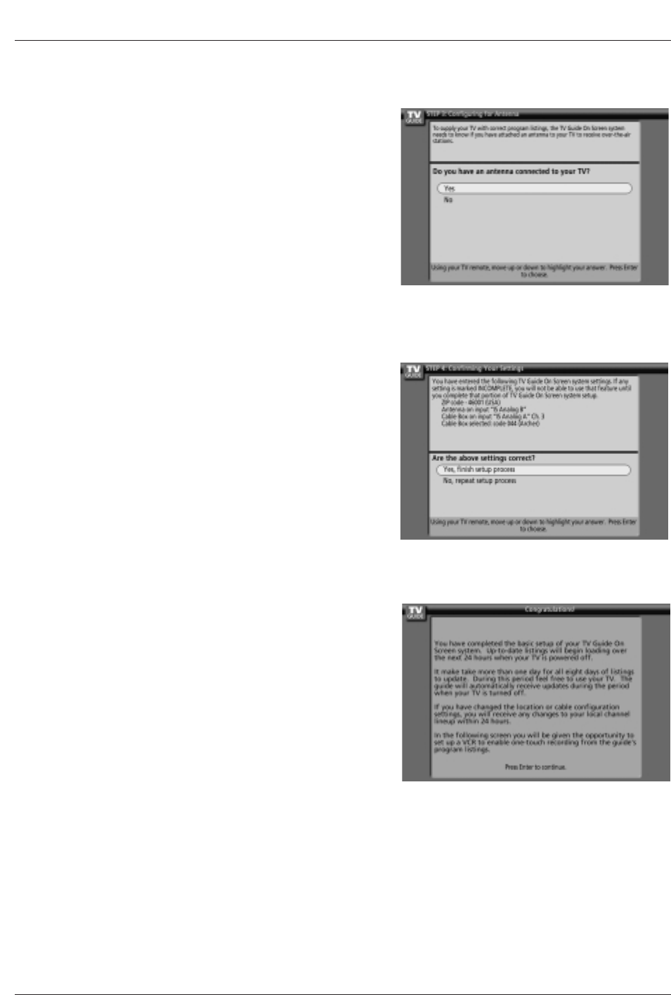
14. Screen 14: Congratulations
• Press ENTER to display Screen 15.
13. Screen 13: Are your basic settings correct?
• If you select Yes, you see Screen 14.
• If you select No, you see Screen 1.
12. Screen 12: Do you have an antenna connected?
• If you select Yes, you see Screen 13.
Note:
• If you selected No in Screen 3 then you must
select Yes in this screen to receive a channel
lineup and listings.
• If you select No, you see Screen 13.
30 Plasma TV
Installation
17. Screen 17: VCR Brand Name
• Use the D/Ebutton to select the brand of the recording device.
• Press ENTER, and you see Screen 18.
16. Screen 16: VCR Configuration Diagram
• This screen shows the correct way to install the G-LINKTM Cable from
the back of the TV to the Recording device.
Make sure the G-LINKTM Cable is properly installed.
• Press ENTER, and you see Screen 17.
15. Screen 15: Is a VCR Connected?
• If you select Yes, you see Screen 16.
• If you select No, you see Screen 21.
Owner’s Manual 31
Installation
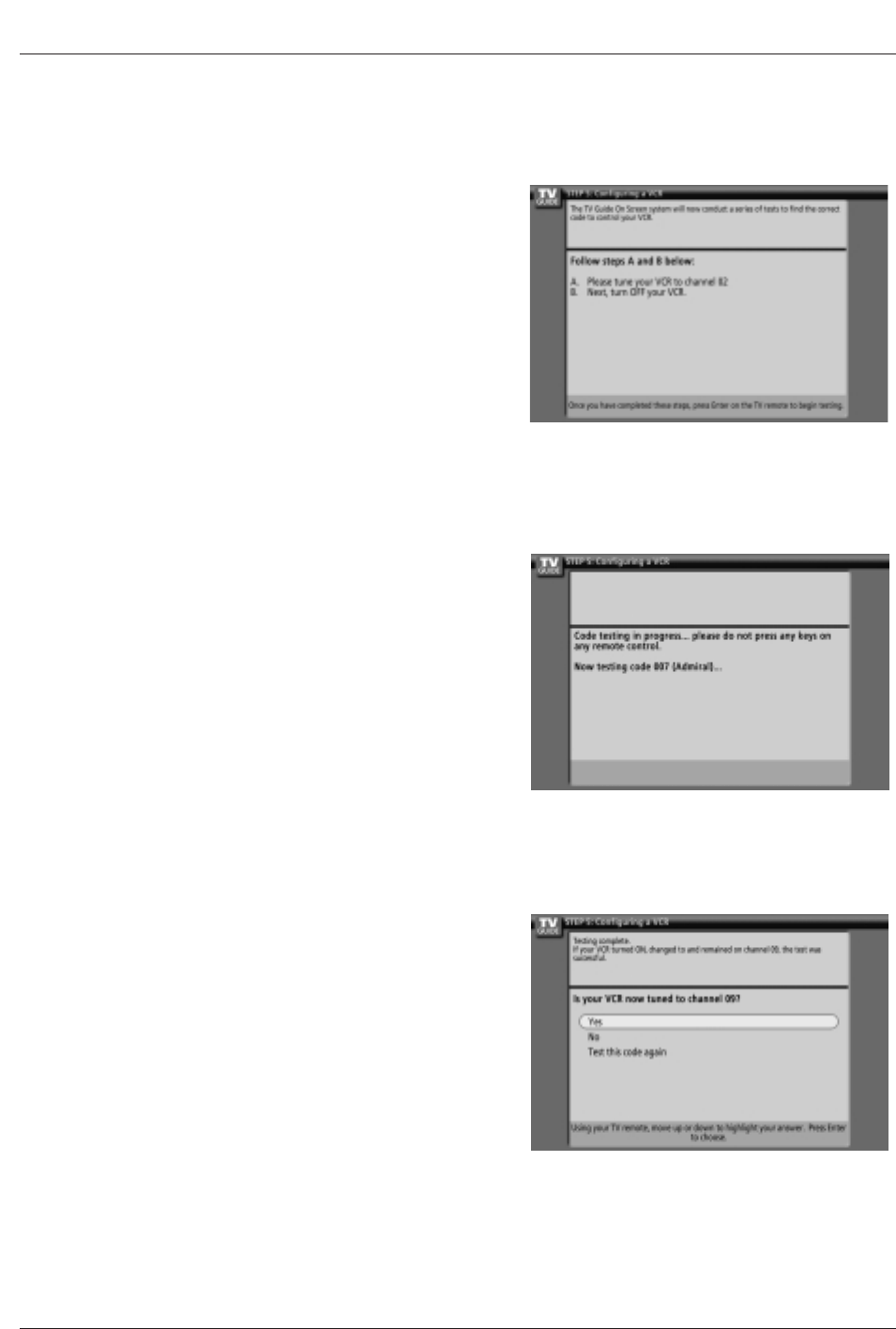
18. Screen 18: VCR Preparation
• Follow the on-screen instructions, and press ENTER to display
Screen 19.
19. Screen 19: VCR Code Testing
• When testing is done, Screen 20 displays automatically.
20. Screen 20: VCR Tuned to Channel 9?
• If you select Yes, you see Screen 21.
• If you select No, a different code is tested in Screen 19.
Notes :
• Many VCRs require testing more than one code.
• If you select Test this code again, the same code is tested again in
Screen 19.
32 Plasma TV
Installation
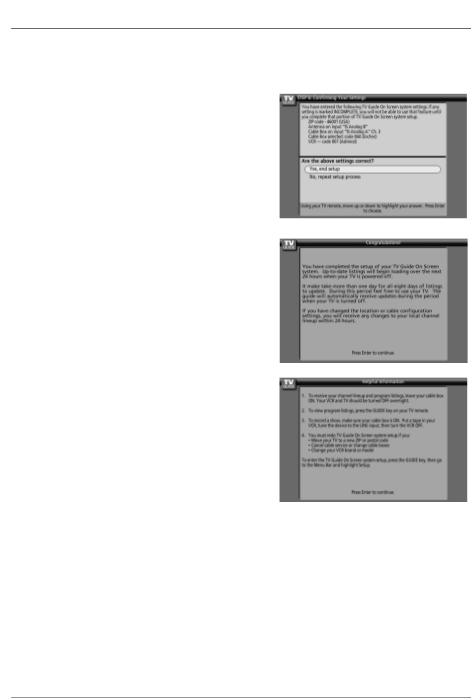
21. Screen 21: Confirming Your Settings
• Verify the Setup information is correct.
• If it is, select Yes, end setup, and you see Screen 22.
• If it is not, select No, repeat setup process, and you see Screen 1.
22. Screen 22: Congratulations
• You have successfully completed Setup!
• Press ENTER and you see Screen 23.
23. Screen 23: Helpful Information
• This screen tells you valuable information on using your TV Guide On
Screen system
.
• Press ENTER to watch TV.
Notes:
• The TV Guide On Screen system receives program listings data through your cable or over-the-air video signal. In order to
receive regular program listings, please remember to do the following:
1. Turn OFF your TV when it is not in use. (Do not unplug the power cord.)
2. If you have a Cable box connected, leave it ON.
3. If you have a VCR connected, turn it OFF when not in use. (Do not unplug the power cord.)
4. If you have more than one Cable system in your area, you may be prompted to select which Cable system’s program data to
download. If so prompted, please follow the on-screen instructions.
Owner’s Manual 33
Operation
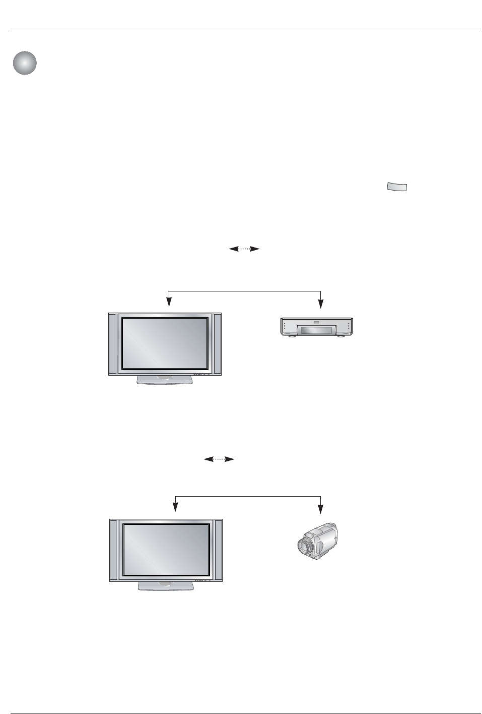
- It's available to communicate to either direction and you can give and take a image, sound, or each control command
with one cable.
W
WHow to connect the 1394
•To operate the IEEE1394, these methods are available as shown below.
1. When connecting the DVHS or the MicroMV Camcorder, as shown in the (a) or (b) figure, press the button to show
the control panel.
IEEE 1394 Functions
IEEE 1394 Functions
1394
Note: When connecting the DVHS and the MicroMV Camcorder, in case of showing ‘input error’, it’s okay.
(a) TV DVHS
<Connect the IEEE1394 Cable>
<Connect the IEEE1394 Cable>
(b) TV MicroMV Camcorder
<TV>
<TV>
<DVHS>
<MicroMV Camcorder>
34 Plasma TV
Operation
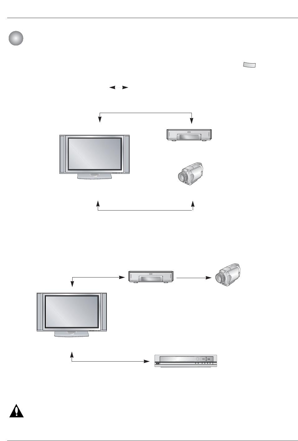
IEEE 1394 Functions
IEEE 1394 Functions
-When connecting the 1394 and then playing, you must use the original DVHS tape. If not, it may
occur errors.
-If the operation normally doesn’t work on Daisy Chain connection, please change an arrangement
of connected device.
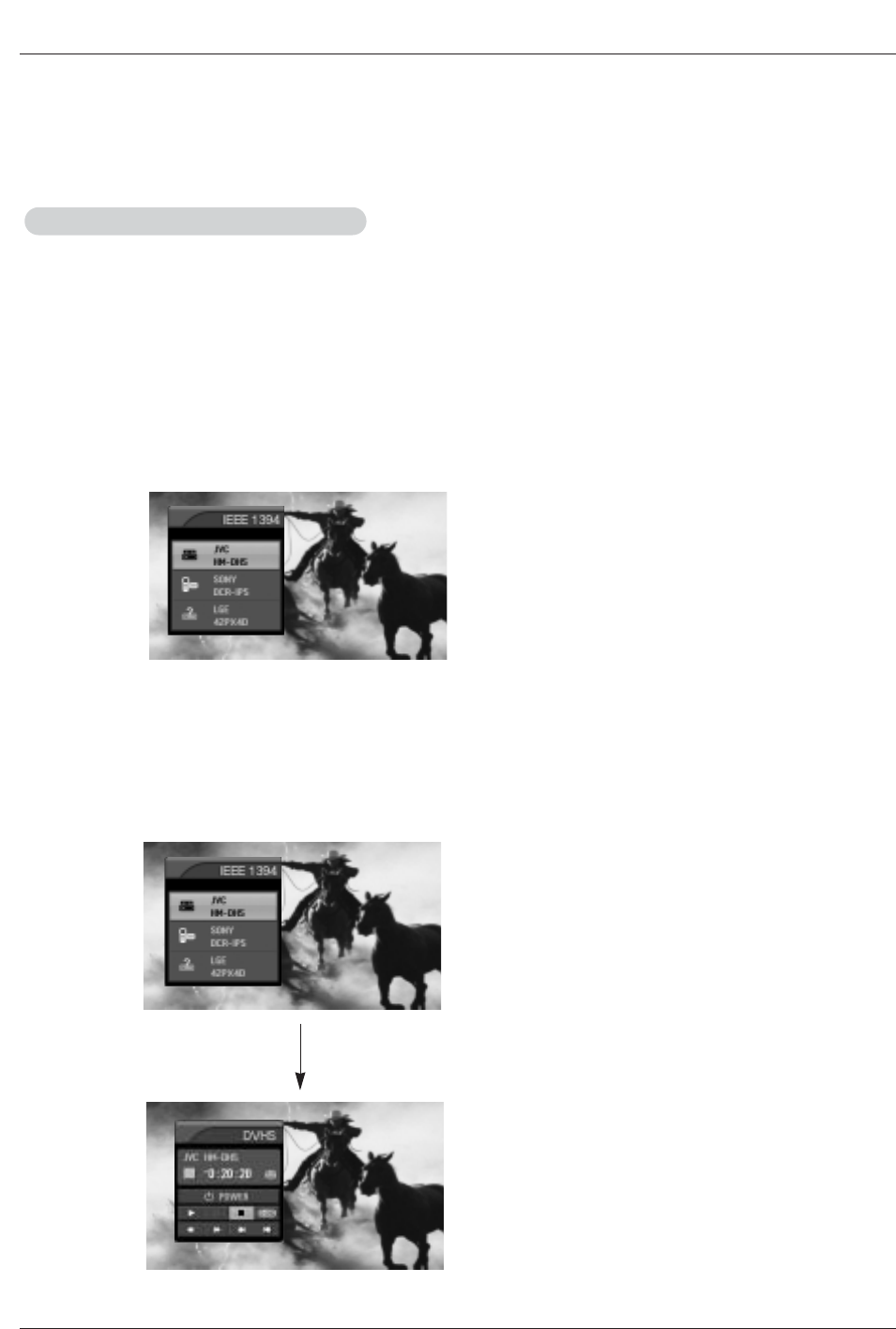
2. When connecting the DVHS and the MicroMV Camcorder, as shown in the (c) or (d) figure, press the button to show
the control panel and then select the DVHS or the MicroMV Camcorder.
1394
(c) TV DVHS + MicroMV Camcorder
<Connect the IEEE1394 Cable>
<TV>
<DVHS>
<MicroMV Camcorder>
<Connect the IEEE1394 Cable>
(d) Daisy Chain Connection
<TV>
<DVHS> <MicroMV Camcorder>
<Generic>
<Connect the
IEEE1394 Cable>
<Connect the IEEE1394 Cable>
<Connect the
IEEE1394
Cable>
Owner’s Manual 35
Operation
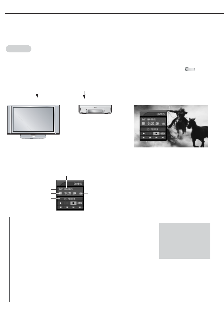
DVHS
DVHS
W
WHow to play the DVHS
<TV>
<DVHS>
1. Connect the IEEE 1394 jack at the TV to the IEEE 1394
jack at the DVHS with IEEE 1394 Cable.
2. When watching the TV, press the button.
1394
<Connect the IEEE1394 Cable>
• The control panel of DVHS
-Depending on the connected equipment, marked control panel may be different.
3
4
• Show the control panel of DVHS.
5
7
6
8
9
12
1. DVHS Model
2. Connected Equipment to the 1394
3. DVHS Company
4. DVHS Operating Status
5. Power On/Off
6. DVHS Play Time
7. Tape Status
• Tape shape Icon - Tape in or not
• Lock shape Icon - Writable or not
8. Initializing Play Time
9. DVHS Play, Pause, Stop, Search, Skip.
(Notes:
• Skip- This function is for a fast search. It searches the program’s start
Skip- point and then plays. On skipping, Search (
FFF
,
GG
), Pause ( II ) and
Skip- Play (
G
) are displayed on the Control Panel. In some models, it’s not
Skip- available to operate the Skipping ( I
FF
,
GG
I) function.
* Supported DVHS List
JVC(HM-DH40000K)
JVC(HM-DH40000U)
JVC(HM-DH5U)
MITSUBISHI(HV-HD1000)
PANASONIC(NV-DH2)
Notes:
• In case the DVHS have a incorrect recognition to Generic, the power of DVHS is completely pull out and then connect
again.
• When searching the screen(
FF
,
GG
) , the DVHS may be strangely seen. And also the DVHS may late respond by devices.
36 Plasma TV
Operation
IEEE 1394 Functions
IEEE 1394 Functions
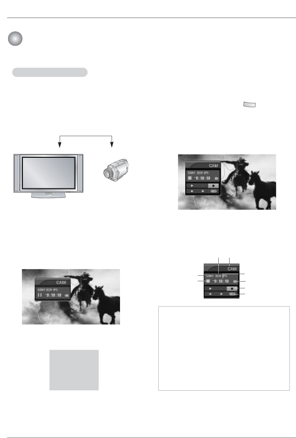
• The control panel of MicroMV Camcorder
-Depending on the connected equipment, marked control panel
-may be different.
1. MicroMV Camcorder Model
2. Connected Equipment to the 1394
3. MicroMV Camcorder Company
4. MicroMV Camcorder Operating Status
5. MicroMV Camcorder Play Time
6. Tape Status
• Tape shape Icon - Tape in or not
• Lock shape Icon - Writable or not
7. MicroMV Camcorder Play, Search, Pause or Stop
8. Initializing Play Time
3
46
5
7
8
12
Notes:
• In memory mode of MicroMV Camcorder , it doesn’t apply to connect the IEEE1394.
• Regardless of a mode of MicroMV Camcorder, if the tape is ejected, it doesn’t apply to connect the IEEE1394.
W
W
V
How to play the MicroMV Camcorder
MicroMV Camcorder
MicroMV Camcorder
1. Connect the IEEE 1394 jack at the TV to the IEEE 1394
jack at the MicroMV Camcorder with IEEE 1394 Cable.
<TV>
<MicroMV Camcorder>
2. When watching the TV, press the button.
1394
• Show the control panel of MicroMV Camcorder.
• Show the control panel of CAM.
* Supported MicroMV Camcorder List
SONY DCR IP-1
SONY DCR IP-5
SONY DCR IP-45
SONY DCR IP-210
<Connect the IEEE1394 Cable>
• In camera mode of MicroMV Camcorder, this control
panel is showed.
Owner’s Manual 37
Operation
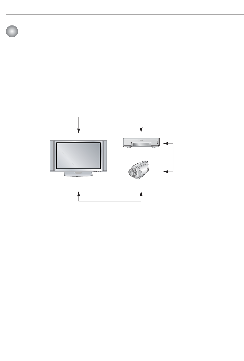
W
WHow to play the MicroMV Camcorder and DVHS
MicroMV Camcorder and DVHS
MicroMV Camcorder and DVHS
1. Synchronously, connect the IEEE 1394 jack of the TV to the IEEE 1394 jack of the DVHS and the
MicroMV Camcorder with IEEE 1394 Cable.
2. Press the D/Ebutton to select device, then press ENTER button to play it . And then selected device
will be showed OSD.
38 Plasma TV
Operation
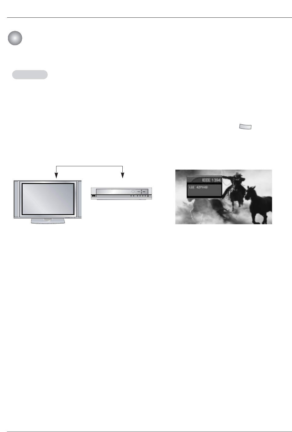
Generic
Generic
W
W
V
How to play the Generic
<TV>
<Generic>
1. Connect the IEEE 1394 jack of the TV to the IEEE 1394
jack of the Generic device with IEEE 1394 Cable.
: If the stream which is satisfied with standard of IEC 61883(MPEG 2 TS Data) inputs, this
is a function which is able to show the stream on the TV screen.
<Connect the IEEE1394 Cable>
2. When watching the TV, press the and then D/E
buttons to select the Generic device and then use the
ENTER button.
1394
3. Press the TV INPUT button to stop the IEEE1394
function.
Note: (Applicable devices) a device which output MPEG 2 TS Data stream through IEEE1394 port.
( ex: LST-3410, Digital Cable STB etc.)
IEEE 1394 Functions
IEEE 1394 Functions
Owner’s Manual 39
Operation
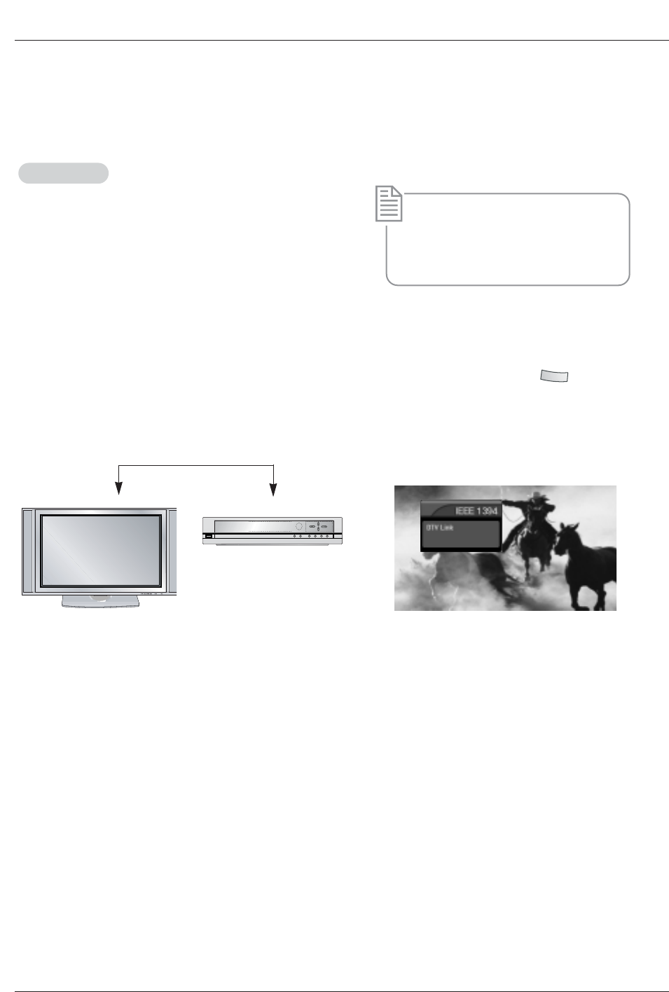
DTV Link
DTV Link : DTV Link applies to 1394 connection of device labeled DTV Link logo.
W
W
V
How to play the DTV Link
<DTV Link-Producer>
1. Connect the IEEE 1394 jack of the TV to the IEEE 1394
jack of the DTV Link supported device IEEE 1394 Cable.
* What’s the DTV Link?
It is normal standard of CEA which restricts
by a remote and displays OSD and plays to
stream of a remote control by using a con-
nection of IEEE1394.
<Connect the IEEE1394 Cable>
2. When watching the TV, press the and then D/E
buttons to select the DTV Link supported device and then
use the ENTER button.
1394
<TV>
3. Press the TV INPUT button to stop the IEEE1394
function.
Note: On a condition of connecting the IEEE 1394, you can control the DTV Link device while watching the OSD through
DTV and DTV remote control.
( ex: change of channel, play, record, a show of recording list etc.)
40 Plasma TV
Operation
W
W
V
Don’t connect !
•When connecting with these 2 methods, the IEEE1394 will not work properly.
(a) LOOP Connection
<Connect the IEEE1394 Cable>
<TV>
<DVHS>
<MicroMV Camcorder>
<Connect the IEEE1394 Cable>
<Connect the
IEEE1394
Cable>
(b) When connecting the 4 devices and over, the 1394 will not work properly.
Note: When the same devices connect with 2 devices and over, it’s undesirable.
IEEE 1394 Functions
IEEE 1394 Functions

Owner’s Manual 41
Operation
TV Guide On Screen
TV Guide On ScreenTM
TM System
System
Overview
-Your new TV contains the TV Guide On Screen system Interactive Program Guide.
-The TV Guide On Screen system has features that help you get the most out of your viewing
experience.
TV Guide On Screen system Overview
The TV Guide On Screen system has the following features:
•Eight days of show listings (today plus seven days).
•Icons that indicate show rating, stereo, HDTV, new episode, etc.
•Intuitive up/down/left/right navigation using your remote control.
•Set shows to Record.
•Schedule show Reminders.
•Search shows by category (e.g., Movies, Sports, Children, etc.).
•Search for shows based on keywords or alphabetically by title.
•Direct tuning to a channel.
•Show information while watching TV.
•Streamlined System Setup and default setting options.
•Channel lineup customization.
•Help screens while in the TV Guide On Screen system.
42 Plasma TV
Operation
TV Guide On Screen
TV Guide On ScreenTM
TM System
System
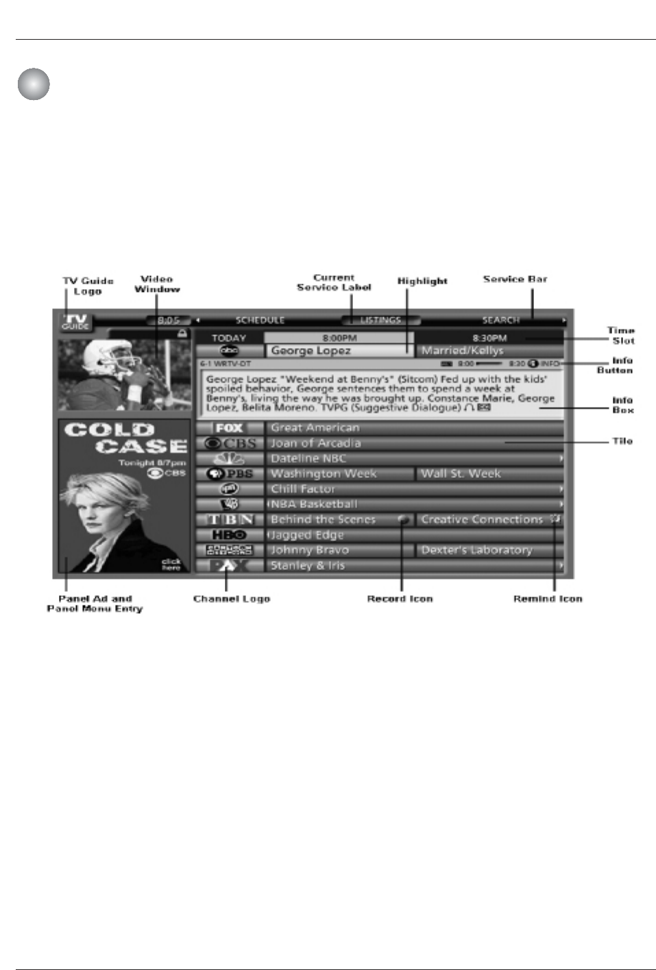
•Video Window - displays TV video while the TV Guide On Screen system is displayed
•Service Bar - provides access to the 4 main Guide Services
•Current Service Label - indented to indicate current Service displayed
•Tile - displays show title
•Highlight - indicates an active tile
•INFO Box - provides information for a highlighted item
•INFO Button - cycles through the various Info Box sizes
•Channel Logo - identifies network
•Record/Remind Icons - indicates a show is set to Record or set as a Reminder
•Panel Ad - location where show- or product-specific information appears (and also where Panel Menu appears)
Screen Components
-The screens displayed in the TV Guide On Screen system share many of the same compo-
nents, as shown in the following figure:
Owner’s Manual 43
Operation
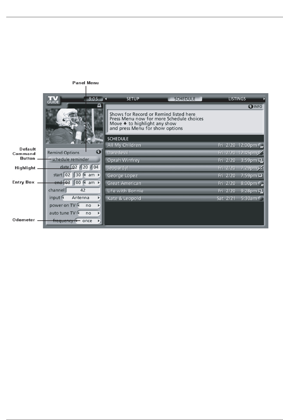
• A Panel Menu appears when the Menu key is pressed on a highlighted tile and additional options are available. It also
appears when you press ENTER on a show starting in the future.
• When a Panel Menu appears, the highlighted tile changes color to indicate the Panel Menu relates to this tile.
• The Panel Menu displays below the Video Window.
• Help is available for a displayed Panel Menu by pressing the INFO button.
• The D/Ebutton move between the options within the Panel Menu.
• The left and right arrows move to adjacent options unless the highlight is on an odometer, where these arrows change the
odometer choice.
• Pressing ENTER from an odometer or number entry box moves the highlight to the default command button of that Panel
Menu, for example, Schedule Reminder.
• Pressing ENTER from a highlighted command button executes the action and closes the Panel Menu (e.g., Schedule
Reminder, Cancel).
• Select Cancel to cancel any changes and press ENTER to close this menu.
• Pressing Menu is a shortcut to Cancel. Press Menu to cancel any changes and close the menu.
• If a Panel Menu contains more menu options than can be displayed on a single screen, D/Ebutton appear at the top or
bottom of a menu. Simply scroll down to access these options.
Panel Menu
44 Plasma TV
Operation
TV Guide On Screen
TV Guide On ScreenTM
TM System
System
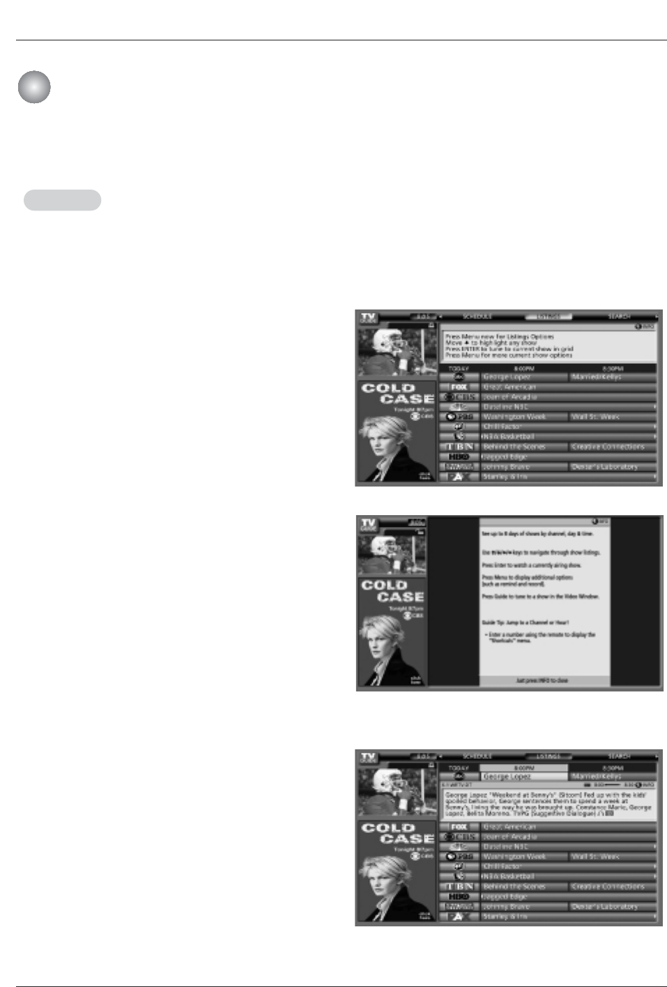
- Access Listings by pressing the TV Guide button on your remote or on the front panel of your TV.
- Listings is always the first Service displayed in the TV Guide On Screen system.
- With Listings highlighted, press the Info button to display a Help screen.
Press the Info button again to close the screen.
•View 8 days of show listings
•Read show descriptions
•Tune directly to a show currently airing
•Set a show to Remind
•Set a show to Record
•Lock and unlock the Video Window
•Access Panel and Channel Ads
Use the D/E/F/Gbuttons to move the highlight
within Listings to:
Notes:
• There may be times when the TV Guide On Screen
system could display partial or no program listings. The
reasons for this include:
1. Program schedule information was not provided to TV
Guide On Screen.
2.The transmission of the program listings was interrupt-
ed.
3.The phrase “No Listings” will be replaced with program
information during the next transmission, which should
occur within the next 24 hours.
4.Please remember to turn off your TV when not in use in
order to receive program listings.
Main Services
Listings
Listings
Owner’s Manual 45
Operation
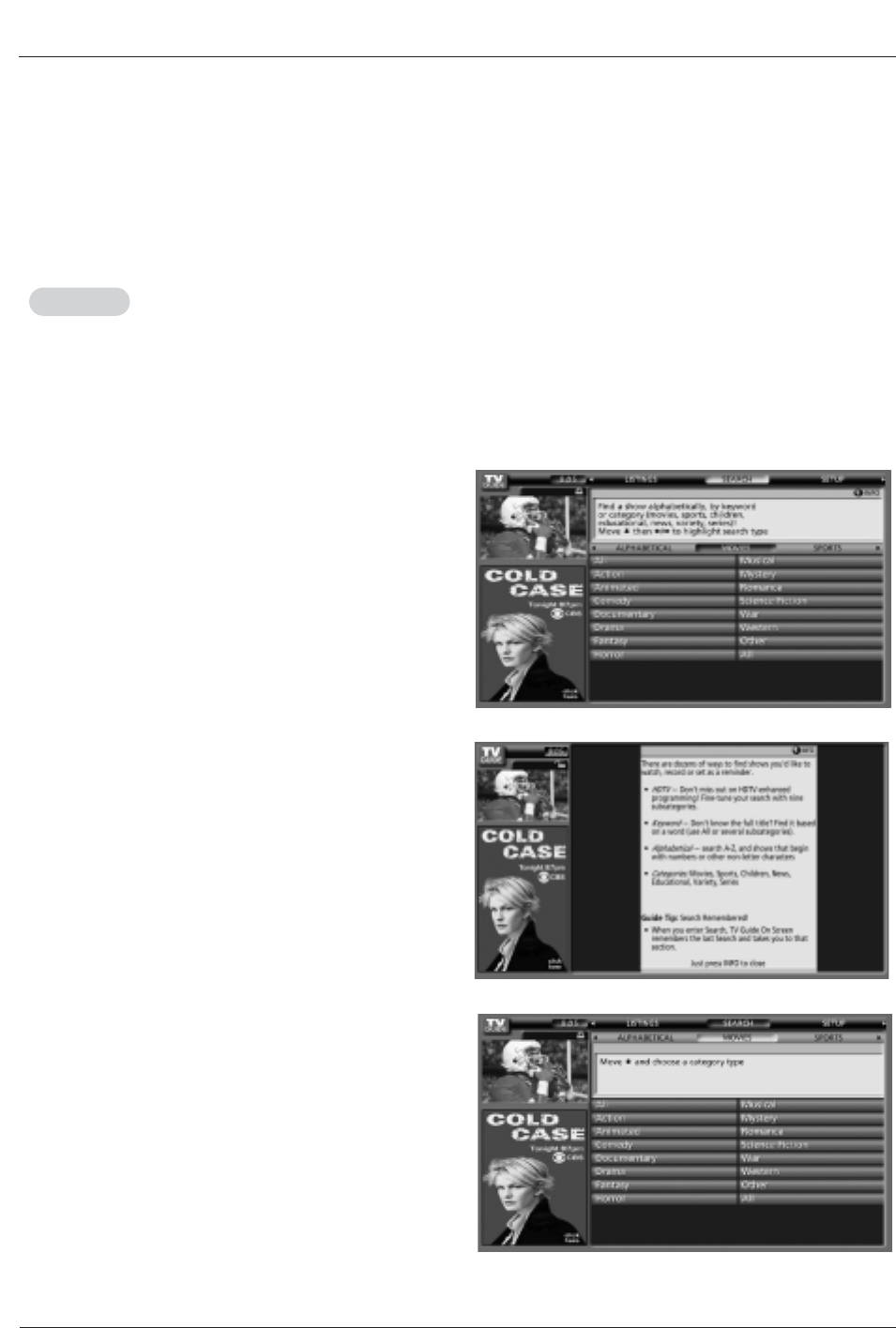
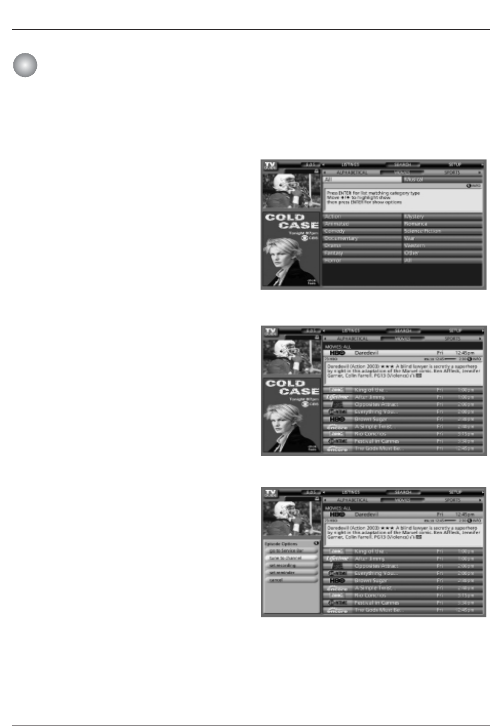
- Search lets you find shows by category (Alphabetical, Movies, Sports, Children, Educational, News, Variety, Series, HDTV) or by
Keyword.
- With Search highlighted, press the INFO button to display a Help screen.
Press the INFO button again to close the screen.
•Category Search Example: Movies
1. From Search, use the Ebutton to highlight Movies.
Search
Search
46 Plasma TV
Operation
TV Guide On Screen
TV Guide On ScreenTM
TM System
System
2. Use the Ebutton to highlight a subcategory (for example, All).
3. Press ENTER to display a list of all Movies, organized by date
and time.
You can choose to set a recording, a reminder, or tune to
the channel.
4. Highlight a show and press ENTER to watch (if on now) or
the Menu key to display the Episode Options menu.
Go to Service Bar - closes the menu, changes no infor-
mation, and returns to the Search Service Bar.
Tune to Channel - exits the TV Guide On Screen system
and tunes to the channel of the highlighted show (show
airs in the future).
Note: This option reads Watch Now if the show is cur-
rently airing.
Set Recording - displays the Record Options menu, from
which you can set frequency, start and end time, etc.
Set Reminder - displays the Remind Options menu, from
which you can set frequency, when, automatically power
On, and auto-tune the TV.
Cancel - closes the menu, changes no information, and
returns to the highlighted show.
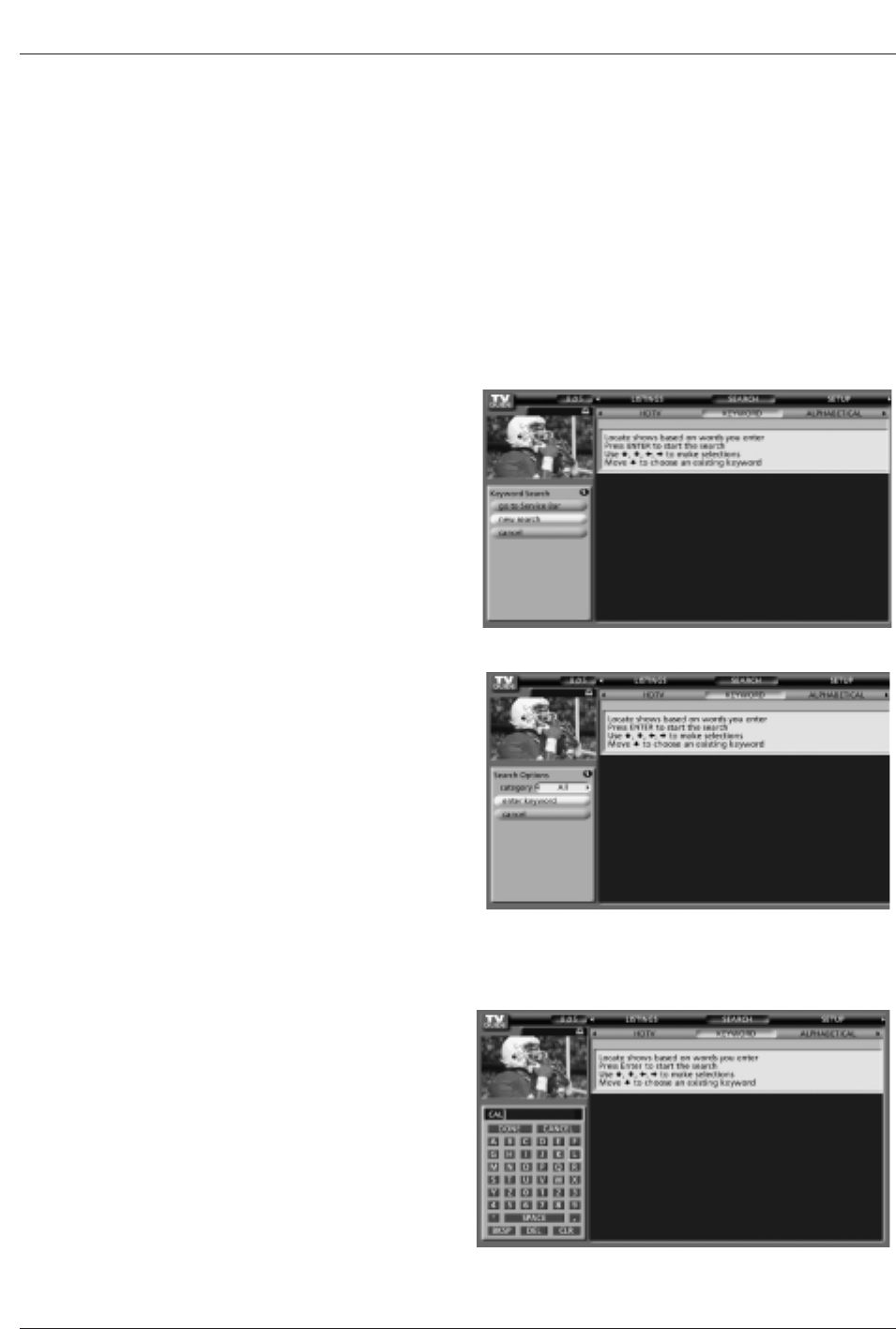
Owner’s Manual 47
Operation
-Keyword search lets you enter a word(s) to look for a particular show by category or for every show title that matches.
• Keyword Search
1. Highlight the Keyword navigation label, and press
ENTER button to display the Keyword Search menu.
2. Highlight New Search, and press ENTER button.
3. The Search Options menu is displayed.
4. Highlight Category, and use the F/Gbutton to select
a category to search (e.g. All, HDTV, Children, Sports,
etc.). When finished, use the Ebutton to highlight
Enter Keyword.
5. Highlight Enter Keyword, and press ENTER.
Then the keyboard is displayed.
6. Use the D/E/F/Gbutton to highlight a character,
and press ENTER to display it. When complete, high-
light Done and press ENTER.
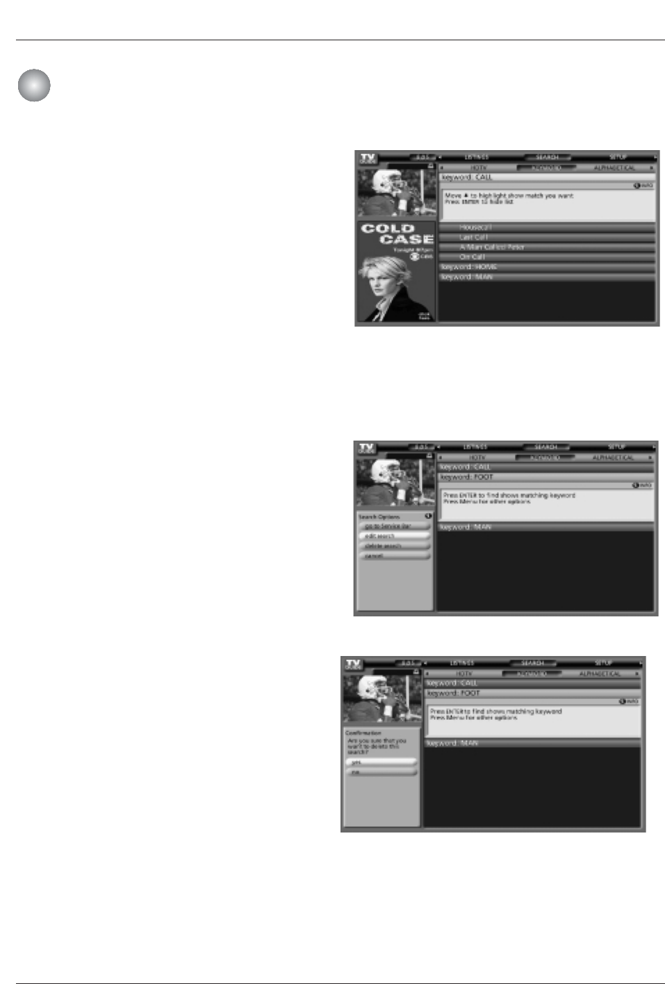
48 Plasma TV
Operation
TV Guide On Screen
TV Guide On ScreenTM
TM System
System
The TV Guide On Screen system stores all the key-
words you create. To edit or delete a keyword, highlight
the keyword and press the Menu key. A Search Options
menu is displayed.
Go to Service Bar - closes the menu, changes no infor-
mation, and returns to the Search Service Bar.
Edit Search - displays the keyboard, where you can
change the keyword.
Delete Search - A Confirm menu is displayed.
•Yes - deletes the Search
• No - closes the panel menu
Cancel - closes the menu, changes no information, and
returns to the highlighted show.
7. A list of all matching shows for that keyword is dis-
played.
Like the Category Search Example, you can highlight
a show, and press ENTER to display all airings. You
can then highlight a specific listing and press ENTER
to watch (if On now) or the Menu key to display the
Episode Options menu.
From the Episode Options menu, choose to set a
recording, a reminder, or tune to the channel, as pre-
viously described.
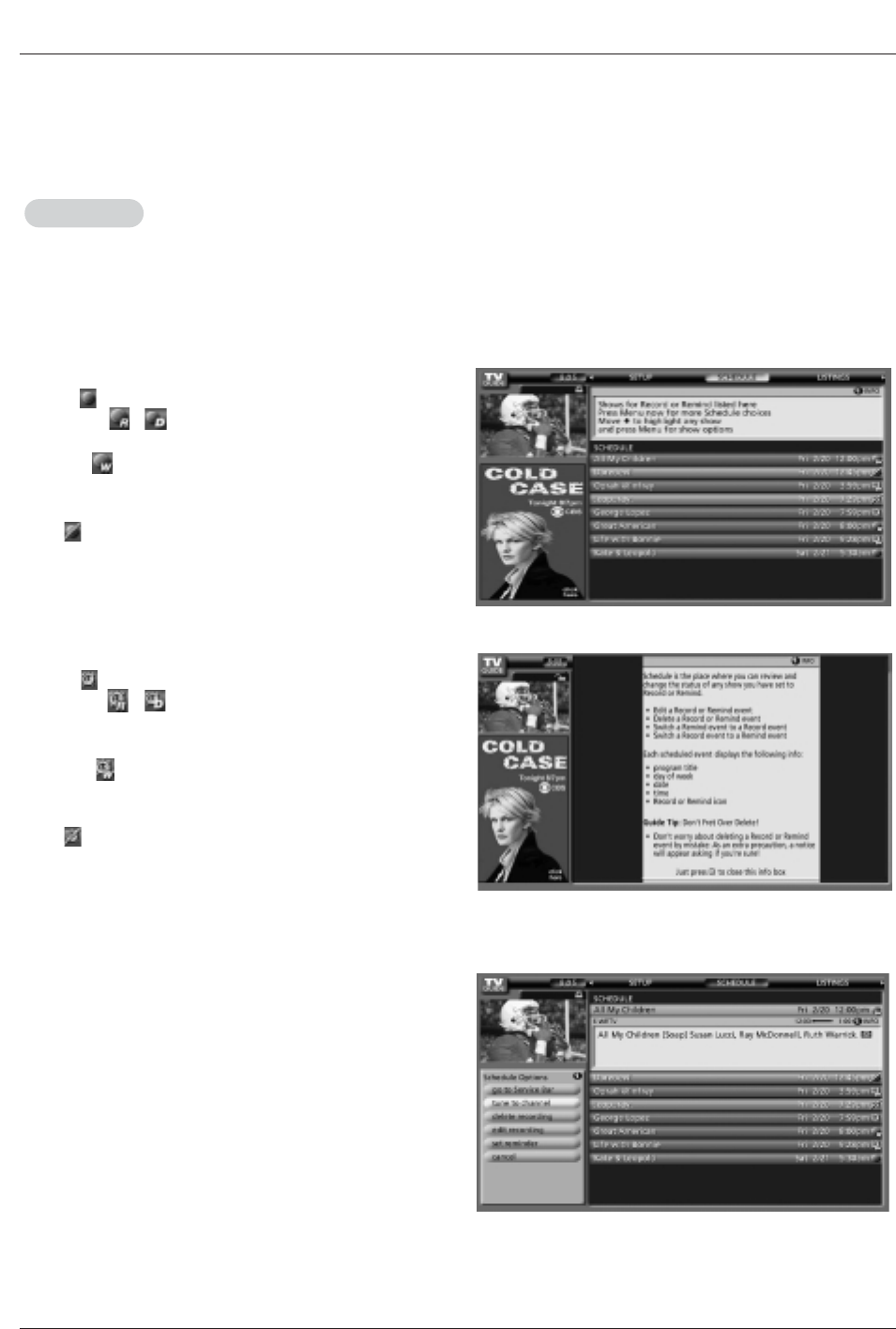
Owner’s Manual 49
Operation
- Schedule lets you review, edit, or delete Record and Remind events that you set previously.
- With Schedule highlighted, press the INFO button to display a Help screen. Press the INFO button again to close the
screen.
- An icon identifies the event type:
Record
WOnce —records the show one time
WRegularly , —records the show every time the
show airs on the same channel and starts at the same time
WWeekly —records the show each time the show airs on
the same day of the week, on the same channel and starts at
the same time
WOff —keeps the show in the list but will not record this
show until the frequency is changed.
Remind
WOnce —sets a show reminder one time
WRegularly , —sets a show reminder every
time the show airs on the same channel and starts at
the same time
WWeekly —sets a show reminder each time the
show airs on the same day of the week, on the same
channel and starts at the same time
WOff —keeps the show in the list but will not remind
until the frequency is changed
Highlight an event, and press the Menu key for options.
Go to Service Bar - closes the menu, changes no information,
and returns to the Schedule Service Bar.
Tune to channel - exits the TV Guide On Screen system and
tunes to the highlighted show.
Delete Recording - removes the recording from the Schedule,
after a Confirm screen.
Edit Recording - opens a menu from which you can change
existing recording information.
Set Reminder - opens a menu from which you can set a
Reminder for the show (Record is not cancelled).
Cancel - closes the menu, changes no information, and returns
to the highlighted show.
Schedule
Schedule
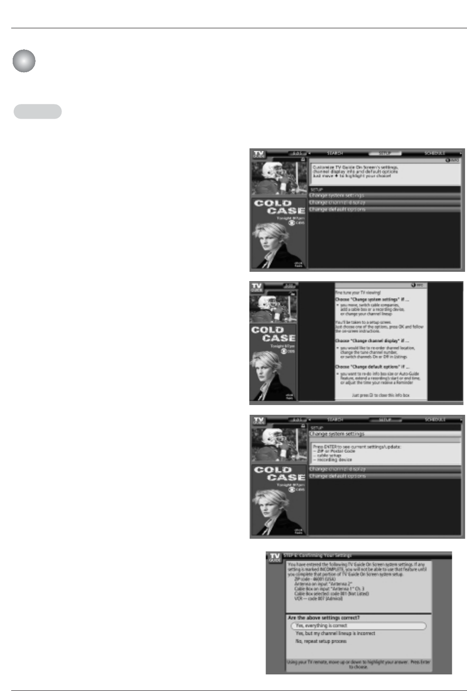
50 Plasma TV
Operation
TV Guide On Screen
TV Guide On ScreenTM
TM System
System
- After you initially complete Guide Setup, you can make changes to Guide settings in the following areas:
• Change System Settings
• Change Channel Display
• Change Default Options
Highlight a choice, press ENTER, and follow the on-screen instruc-
tions.
• Change System Settings
This option appears after you have completed the initial Guide
Setup process.
Press ENTER to display the Confirming Your Settings screen. You
see your current settings.
Choose one of the options, press ENTER, and follow the on-screen
instructions.
With Setup highlighted, press the INFO button to display a Help
screen. Press the INFO button again to close the screen.
Setup
Setup
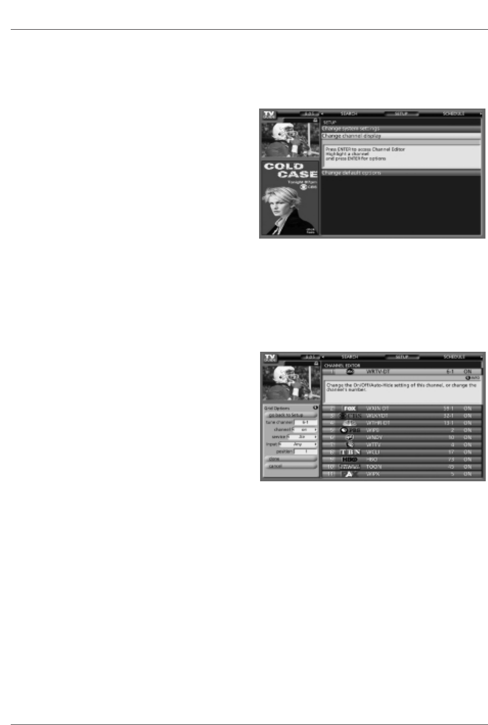
Owner’s Manual 51
Operation
Press ENTER to display the Channel Editor screen.
Then, highlight a channel and press Menu. A Grid Options
menu is displayed.
Highlight Go Back to Setup to close the menu, change no
information, and return to the Setup Service Bar.
Or make changes and when finished, press ENTER to high-
light Done. Press ENTER again to close the menu and
accept the changes.
Highlight Cancel to close the menu, change no information,
and return to the highlighted channel.
• Change Channel Display
Change Channel Display lets you edit channel information
that appears in Listings. With Change Channel Display
you can :
•Change the position number to indicate where in the
Listings the channel displays
•Change the tune channel number
•Switch a channel
WOn - the channel is always displayed
WOff - the channel is never displayed
WAuto-Hide - the channel is only displayed when
program information is available.
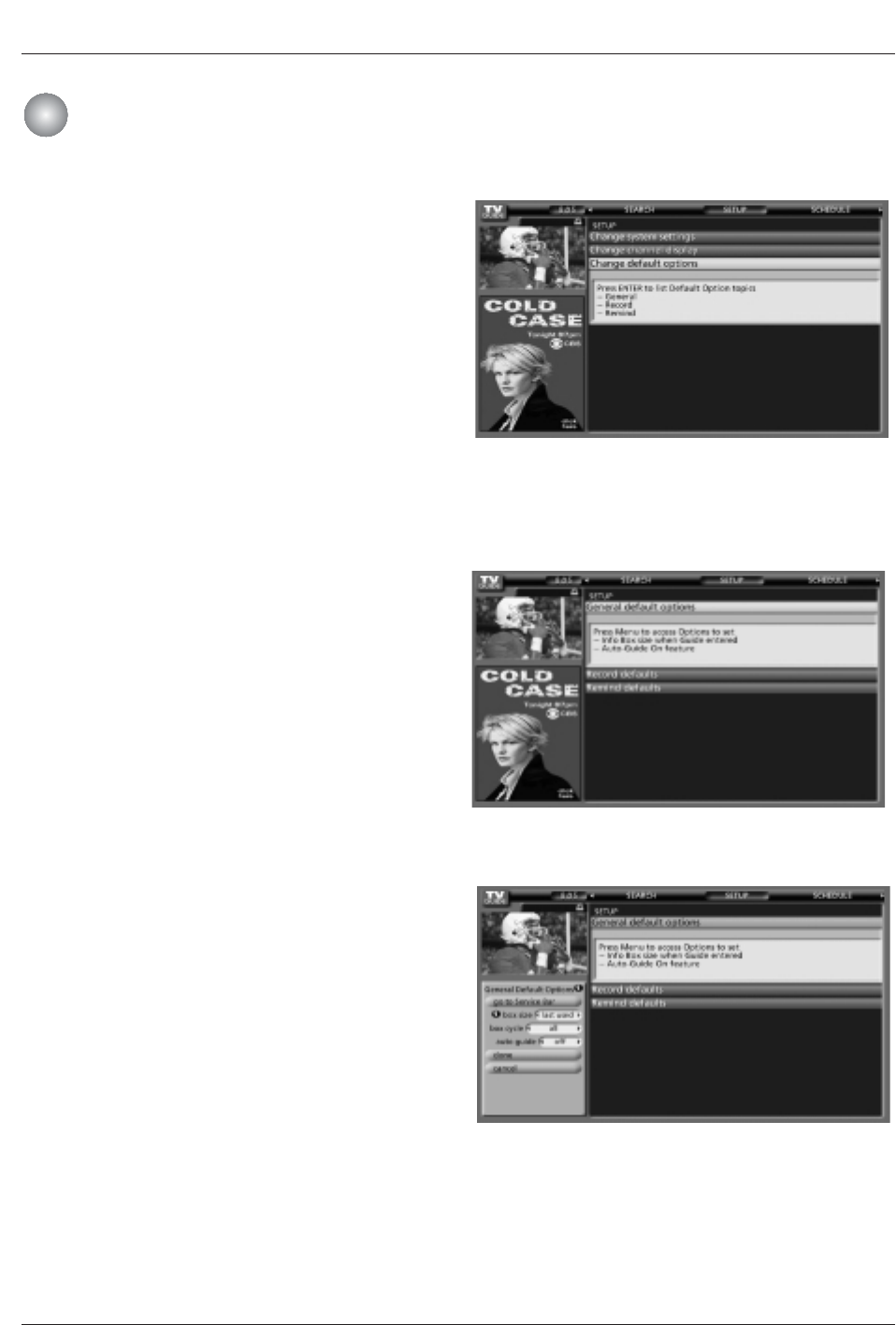
52 Plasma TV
Operation
TV Guide On Screen
TV Guide On ScreenTM
TM System
System
General Default Options lets you set defaults for the following:
•The initial Info Box size when the TV Guide On Screen system
is entered.
Choices are No, Small, Large, and Last Used
(Default = Last Used).
•The Info Box size rotation when the Info key is pressed while in
the TV Guide On Screen system.
Choices are No only, Small only, Large only, No & Small, No &
Large, Small & Large, All (Default = All)
•Automatic entry into the TV Guide On Screen system (Auto-
Guide) when the TV is powered On.
Choices are On and Off (Default = On).
Highlight General Default Options, and press the Menu key to dis-
play the General Default Options menu.
Highlight Go to Service Bar to close the menu, change no infor-
mation, and return to the Setup Service Bar.
When finished, press ENTER to highlight Done. Press ENTER
again to close the menu and accept the changes.
Highlight Cancel to close the menu, change no information, and
return to the highlighted option.
• Change Default Options
Change Default Options lets you change default settings in
the following categories:
•General Default Options
•Record Defaults
•Remind Defaults
Highlight Change Default Options, and press ENTER.
<General Default Options>
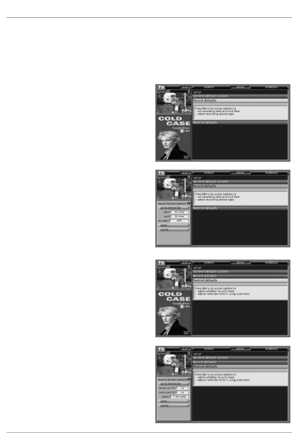
Owner’s Manual 53
Operation
< Record Defaults>
• Record Default Options lets you set defaults for the following:
• When to start the record event. Choices are 120 minutes early to
120 minutes late, to On time. (Default = On time)
• When to end the record event. Choices are 120 minutes early to
120 minutes late, to On time. (Default = On time)
• Recorder choice: Please choose the VCR only. This TV does not
support other devices with a recording feature.
Highlight Record Defaults, and press the Menu key to display the
Record Default Options menu.
Highlight Go to Service Bar to close the menu, change no infor-
mation, and return to the Setup Service Bar.
< Remind Defaults>
Remind Default Options lets you set defaults for the following:
• Power On the TV, if Off, when a Reminder is scheduled. Choices
are Yes and No.
(Default = No)
• Automatically tune the TV to the channel (TV must be On), when
a Reminder is scheduled. Choices are Yes and No.
(Default = No)
• When to display the reminder screen. Choices are 30 seconds to
15 minutes early, to 30 seconds to 15 minutes late, to On time.
(Default = 1 min early)
Highlight Remind Defaults, and press the Menu key to display the
Remind Default Options menu.
Highlight Go to Service Bar to close the menu, change no infor-
mation, and return to the Setup Service Bar.
When finished, press ENTER to highlight Done. Press ENTER
again to close the menu and accept the changes.
Highlight Cancel to close the menu, change no information, and
return to the highlighted option.
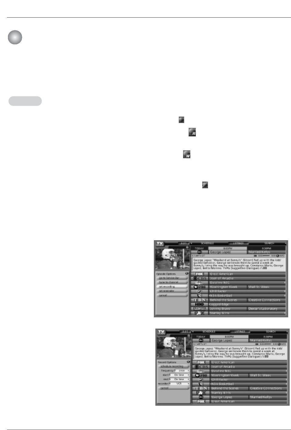
54 Plasma TV
TV Guide On Screen
TV Guide On ScreenTM
TM System
System
Operation
WOnce —records the show one time
WRegularly —records the show every time the show
airs on the same channel and starts at the same time
WWeekly —records the show each time the show
airs on the same day of the week, on the same channel
and starts at the same time
WOff (not cancel) —keeps the show in the list but
will not record this show until the frequency is changed.
WCancel (no icon displayed)—does not record
2) From a Panel Menu
• Highlight a show, and press Menu to display the Episode
Options menu.
• Highlight Set Recording, and press ENTER to display the
Record Options menu.
• Highlight the Frequency option, and use the left and right
arrows to choose among Once, Regularly, Weekly, and Off,
as previously described.
• Recorder choice: Please choose the VCR only. This TV does
not support other devices with a recording feature.
Note: Video Window Lock is switched to on or off using PIP
button in Listings mode.
You can set a show to Record in Listings, Search, and
Schedule or change Record settings for a show in Schedule.
There are 3 ways to set a show to Record:
1) Using the Record Button on the Remote
• Press the Record button on the remote to record the show
Once with current default settings (Start and End recording
On Time). Each time you press the Record button, you
change the record frequency (but not the default settings)
among Once (default), Regularly, Weekly, Off, and then
Cancel.
Note: The proper Record icon appears on the show tile, as
the Record button is pressed.
Record
Record
Record And Remind Features