LG Electronics USA 42PX7DCUA Plasma Display Panel User Manual U558A 42PX7DC
LG Electronics USA Plasma Display Panel U558A 42PX7DC
Contents
- 1. User Manual 1
- 2. User Manual 2
User Manual 1

PLASMA TV
OWNER’S MANUAL
Please read this manual carefully and completely before
operating your TV.
Retain this manual for future reference.
Record model number and serial number of the TV in the
spaces provided below.
See the label attached on the back cover and relate this
information to your dealer if you require service.
Model Number :
Serial Number :
MODEL: 42PX7DC
LG Electronics U.S.A., Inc.
2 Plasma TV
Warning/Caution
WARNING/CAUTION:
TO REDUCE THE RISK OF ELECTRIC SHOCK DO NOT REMOVE COVER (OR BACK). NO USER
SERVICEABLE PARTS INSIDE. REFER TO QUALIFIED SERVICE PERSONNEL.
The lightning flash with arrowhead symbol, within an equilateral triangle, is intended to alert the user to
the presence of uninsulated “dangerous voltage” within the product’s enclosure that may be of suffi-
cient magnitude to constitute a risk of electric shock to persons.
The exclamation point within an equilateral triangle is intended to alert the user to the presence of
important operating and maintenance (servicing) instructions in the literature accompanying the appli-
ance.
WARNING/CAUTION:
TO PREVENT FIRE OR SHOCK HAZARDS, DO NOT EXPOSE THIS PRODUCT TO RAIN OR MOISTURE.
FCC NOTICE
• A Class B digital device
This equipment has been tested and found to comply with the limits for a Class B digital device, pursuant to Part
15 of the FCC Rules. These limits are designed to provide reasonable protection against harmful interference in
a residential installation. This equipment generates, uses and can radiate radio frequency energy and, if not
installed and used in accordance with the instructions, may cause harmful interference to radio communications.
However, there is no guarantee that interference will not occur in a particular installation. If this equipment does
cause harmful interference to radio or television reception, which can be determined by turning the equipment off
and on, the user is encouraged to try to correct the interference by one or more of the following measures:
- Reorient or relocate the receiving antenna.
- Increase the separation between the equipment and receiver.
- Connect the equipment into an outlet on a circuit different from that to which the receiver is connected.
- Consult the dealer or an experienced radio/TV technician for help.
• Any changes or modifications not expressly approved by the party responsible for compli-
ance could void the user’s authority to operate the equipment.
CAUTION:
Do not attempt to modify this product in any way without written authorization from LG Electronics. Unauthorized mod-
ification could void the user’s authority to operate this product.
COMPLIANCE:
The responsible party for this device compliance is:
Zenith Electronics Corporation
1-201-816-2000
Marked and Distributed in the United States by LG Electronics U.S.A., Inc.
1000 Sylvan Avenue, Englewood Cliffs, NJ 07632
http://www.zenith.com
WARNING
RISK OF ELECTRIC SHOCK
DO NOT OPEN
/CAUTION
WARNING/CAUTION
TO REDUCE THE RISK OF FIRE AND ELECTRIC SHOCK, DO NOT EXPOSE THIS PRODUCT TO
RAIN OR MOISTURE.
W
Warning/Caution
arning/Caution

Operating Guide 3
Safety Instructions
IMPORTANT SAFETY INSTRUCTIONS
Important safety instructions shall be provided with each apparatus. This information shall be given in a separate booklet or
sheet, or be located before any operating instructions in an instruction for installation for use and supplied with the appara-
tus. This information shall be given in a language acceptable to the country where the apparatus is intended to be used. The
important safety instructions shall be entitled “Important Safety Instructions”. The following safety instructions shall be includ-
ed where applicable, and, when used, shall be verbatim as follows. Additional safety information may be included by adding
statements after the end of the following safety instruction list. At the manufacturer’s option, a picture or drawing that illus-
trates the intent of a specific safety instruction may be placed immediately adjacent to that safety instruction :
1. Read these instructions.
2. Keep these instructions.
3. Heed all warnings.
4. Follow all instructions.
5. Do not use this apparatus near water.
6. Clean only with dry cloth.
7. Do not block any ventilation openings. Install in accordance with the manufacturer’s instructions.
8. Do not install near any heat sources such as radiators, heat registers, stoves, or other apparatus (including ampli-
fiers)that produce heat.
9. Do not defeat the safety purpose of the polarized or grounding-type plug. A polarized plug has two blades with
one wider than the other. A grounding type plug has two blades and a third grounding prong, The wide blade or the
third prong are provided for your safety. If the provided plug does not fit into your outlet, consult an electrician for
replacement of the obsolete outlet.
10. Protect the power cord from being walked on or pinched particularly at plugs, convenience receptacles, and the
point where they exit from the apparatus.
11. Only use attachments/accessories specified by the manufacturer.
12. Use only with the cart, stand, tripod, bracket, or table specified by the manufacturer, or sold with the apparatus.
When a cart is used, use caution when moving the cart/apparatus combination to avoid injury from tip-over.
Safety Instructions
Safety Instructions
PORTABLE CART WARNING

4 Plasma TV
Safety Instructions
13. Unplug this apparatus during lightning storms or when unused for long periods of time.
14. Refer all servicing to qualified service personnel. Servicing is required when the apparatus has been damaged
in any way, such as power-supply cord or plug is damaged, liquid has been spilled or objects have fallen into
the apparatus, the apparatus has exposed to rain or moisture, does not operate normally, or has been dropped.
15. CAUTION concerning the Power Cord :
Most appliances recommend they be placed upon a dedicated circuit; that
is, a single outlet circuit which powers only that appliance and has no
additional outlets or branch circuits. Check the specification page of
this owner's manual to be certain.
Do not overload wall outlets. Overloaded wall outlets, loose or damaged
wall outlets, extension cords, frayed power cords, or damaged or
cracked wire insulation are dangerous. Any of these conditions could
result in electric shock or fire. Periodically examine the cord of your
appliance, and if its appearance indicates damage or deterioration,
unplug it, discontinue use of the appliance, and have the cord replaced
with an exact replacement part by an authorized servicer.
Protect the power cord from physical or mechanical abuse, such as being
twisted, kinked, pinched, closed in a door, or walked upon. Pay
particular attention to plugs, wall outlets, and the point where the
cord exits the appliance.
16. Outdoor Use Marking :
WARNING - To Reduce The Risk Of Fire Or Electric Shock, Do Not Expose This Appliance To Rain Or Moisture.
17. Wet Location Marking :
Apparatus shall not be exposed to dripping or splashing and no objects filled with liquids, such as vases, shall
be placed on the apparatus.
Safety Instructions
Safety Instructions

Operating Guide 5
Contents
After reading this manual, keep it handy for future reference.
Warning/Caution . . . . . . . . . . . . . . . . . . . . . . . . . . . . . . . .2
Safety Instructions . . . . . . . . . . . . . . . . . . . . . . . . . . . . .3~4
Introduction
Controls . . . . . . . . . . . . . . . . . . . . . . . . . . . . . . .7
Connection Options . . . . . . . . . . . . . . . . . . . . . .8
Remote Control Key Functions . . . . . . . . . . . 9~10
Installation
Accessories . . . . . . . . . . . . . . . . . . . . . . . . . . . . .11
Installation Instructions
Joining the TV assembly to the wall to protect the set
tumbling . . . . . . . . . . . . . . . . . . . . . . . . . . . . . . . . .11
Desktop Pedestal Installation . . . . . . . . . . . . . . . .12
External Equipment Connections
Antenna Connection . . . . . . . . . . . . . . . . . . . . .13
VCR Setup . . . . . . . . . . . . . . . . . . . . . . . . . . .14
External A/V Source Setup . . . . . . . . . . . . . . . .14
DVD Setup . . . . . . . . . . . . . . . . . . . . . . . . . . . .15
HDSTB Setup . . . . . . . . . . . . . . . . . . . . . . . . .16
PC Setup . . . . . . . . . . . . . . . . . . . . . . . . . .17~18
Digital Audio Output . . . . . . . . . . . . . . . . . . . . .19
Operation
Turning the TV On . . . . . . . . . . . . . . . . . . . . . . . .20
On-screen Menus Language Selection . . . . . . . . .20
Setup Menu Options
EZ Scan (Channel Search) . . . . . . . . . . . . . . . .21
Manual Scan . . . . . . . . . . . . . . . . . . . . . . . . . .21
Channel Edit . . . . . . . . . . . . . . . . . . . . . . . . . . .22
DTV Signal Strength . . . . . . . . . . . . . . . . . . . . .22
Channel Label Setup . . . . . . . . . . . . . . . . . . . .23
Input Source . . . . . . . . . . . . . . . . . . . . . . . . . . .23
Video Menu Options
EZ Picture . . . . . . . . . . . . . . . . . . . . . . . . . . . .24
Manual Picture Control (Custom Option) . . . . . .24
Color Temperature Control . . . . . . . . . . . . . . . .24
Video Reset . . . . . . . . . . . . . . . . . . . . . . . . . . .24
Audio Menu Options
Audio Language . . . . . . . . . . . . . . . . . . . . . . . .25
EZ SoundRite / EZ Sound . . . . . . . . . . . . . . . . .25
Manual Sound Control (Custom Option) . . . . . .25
Front Surround . . . . . . . . . . . . . . . . . . . . . . . . .26
TV Speakers On/Off Setup . . . . . . . . . . . . . . . .26
BBE . . . . . . . . . . . . . . . . . . . . . . . . . . . . . . . . .27
Stereo/SAP Broadcasts Setup . . . . . . . . . . . . . .27
Time Menu Options
Auto Clock Setup . . . . . . . . . . . . . . . . . . . . . . .28
Manual Clock Setup . . . . . . . . . . . . . . . . . . . . .28
On/Off Timer Setup . . . . . . . . . . . . . . . . . . . . .28
Sleep Timer / Auto Off . . . . . . . . . . . . . . . . . . . .29
Option Menu Features
Aspect Ratio Control . . . . . . . . . . . . . . . . . . . . .30
Cinema 3:2 Mode Setup . . . . . . . . . . . . . . . . . .30
Caption . . . . . . . . . . . . . . . . . . . . . . . . . . . . . . .31
Caption / Text . . . . . . . . . . . . . . . . . . . . . . . . . .31
Caption Option . . . . . . . . . . . . . . . . . . . . . . . .32
ISM Method . . . . . . . . . . . . . . . . . . . . . . . . . . .32
Low Power . . . . . . . . . . . . . . . . . . . . . . . . . . . .33
Lock Menu Options
Parental Lock Setup . . . . . . . . . . . . . . . . . . . . .35
EPG (Electronic Program Guide) . . . . . . . . . . . . .36
Brief Info. . . . . . . . . . . . . . . . . . . . . . . . . . . . . . . .37
Mute . . . . . . . . . . . . . . . . . . . . . . . . . . . . . . . . . .38
Freeze . . . . . . . . . . . . . . . . . . . . . . . . . . . . . . . . .38
Screen Setup for PC mode . . . . . . . . . . . . . . . . . .39
External Control Device Setup . . . . . . . . . . . . . . . .40~45
IR Codes . . . . . . . . . . . . . . . . . . . . . . . . . . . . . . . .46~47
Programming the Remote . . . . . . . . . . . . . . . . . . . . . .48
Programming Codes . . . . . . . . . . . . . . . . . . . . . . .49~50
Troubleshooting Checklist . . . . . . . . . . . . . . . . . . . . . .51
Maintenance . . . . . . . . . . . . . . . . . . . . . . . . . . . . . . . . .52
Product Specifications . . . . . . . . . . . . . . . . . . . . . . . . .53
Warranty . . . . . . . . . . . . . . . . . . . . . . . . . . . . . . . . .55~56
Contents
Contents
Setup and Operation Checklist
Setup and Operation Checklist
Setup and Operation Checklist
(See pages 13~21 for available connection and operational setup options.)
1. Unpack TV and all accessories.
2. Connect all external video and audio equipment.
see pages 13~18.
3 Install batteries in remote control.
See page 9.
4. Turn TV on.
See page 22.
5. Turn video source equipment on.
6. Select viewing source for TV.
See pages 25.
7. Fine-tune source image and sound to your personal prefer-
ence or as required by source.
See pages 26~ 29.
8. Additional features set up
See Contents above.

6 Plasma TV
Introduction
Introduction
Introduction
What is a Plasma Display Panel (PDP)?
A plasma display panel is the latest display technology and the best way to achieve flat panel displays with excellent image quality
and large screen sizes that are easily viewable. The PDP can be thought of as a descendant of the neon lamp and it can be also
be viewed as a series of fluorescent lamps.
How does it work?
PDP is an array of cells, known as pixels, which are comprised of 3 sub pixels, corresponding to the colors red, green, and blue.
Gas in a plasma state is used to react with phosphors in each sub-pixel to produce colored light (red, green, or blue). These phos-
phors are the same types used in Cathode Ray Tube (CRT) devices such as televisions and common computer monitors.
You get the rich, dynamic colors that you expect. Each sub-pixel is individually controlled by advanced electronics to produce over
16 million different colors. All of these mean that you get perfect images that are easily viewable in a display that is less than 5
inches thick.
160° - Wide angle range of vision
Your flat panel plasma screen offers an exceptionally broad viewing angle -- over 160 degrees. This means that the display is
clear and visible to viewers anywhere in the room who can see the screen.
Wide Screen
The screen of the Plasma Display is so wide that your viewing experience is as if you are in a theater.
Multimedia
Connect your plasma display to a PC and you can use it for conferencing, games, and Internet browsing.
Versatile
The light weight and thin size makes it easy to install your plasma display in a variety of locations where conventional TVs will not
fit.
The PDP Manufacturing Process: a few minute colored dots may be present on the PDP screen
The PDP (Plasma Display Panel), which is the display device of this product, is composed of 0.9 to 2.2 million cells. A few cell
defects will normally occur in the PDP manufacturing process. Several tiny, minute colored dots visible on the screen should be
acceptable. This also occurs in other PDP manufacturers' products. The tiny dots appearing does not mean that this PDP is defec-
tive. Thus a few cell defects are not sufficient cause for the PDP to be exchanged or returned. Our production technology mini-
mizes these cell defects during the manufacture and operation of this product.
Operating Guide 7
Introduction
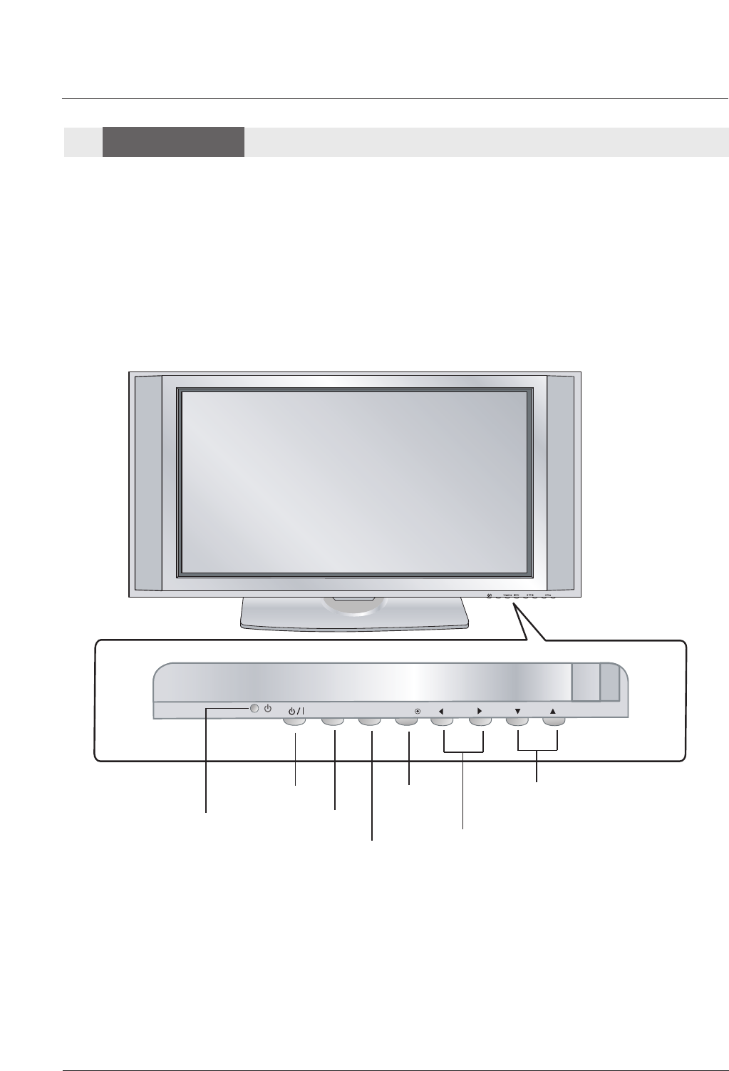
- This is a simplified representation of front panel.
Here shown may be somewhat different from your TV.
Controls
Controls
Front Panel Controls
Front Panel Controls
TV GUIDE
CH
VOL
MENUINPUT ENTER
POWER Button
Remote Control Sensor
VOLUME (FF,GG) Buttons
CHANNEL (EE, DD) Buttons
MENU Button
INPUT Button
ENTER Button
8 Plasma TV
Introduction
AUDIO IN(RGB/DVI)AUDIO IN(RGB/DVI)
SPEAKER OUT(8 )SPEAKER OUT(8 )
SERVICE ONLYSERVICE ONLY
AC IN
2
ANTENNA
ANTENNA INANTENNA IN M.P.IM.P.I
L/MONOMONO
R
AUDIO
VIDEO
INTERFACEINTERFACE
RESETRESETRESETRESET UPDATEUPDATEUPDATEUPDATE
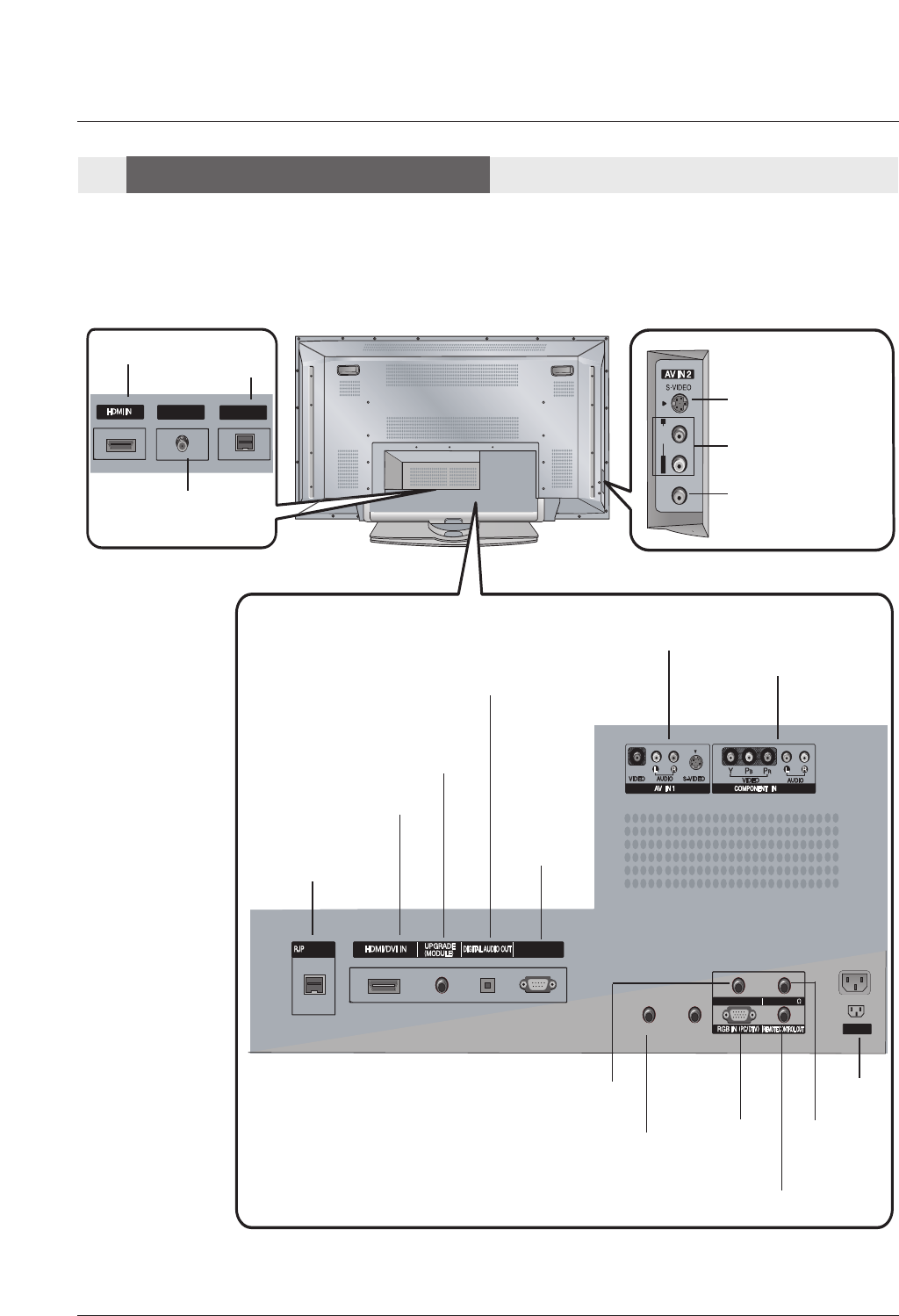
S-VIDEO Input
VIDEO Input
AUDIO Input
Connection Options
Connection Options
Back Connection Panel
Back Connection Panel
AC IN
AUDIO IN(RGB/DTV)
RGB IN(PC/DTV)
REMOTE CONTROL Port
SPEAKER
OUT
RJP INTERFACE
HDMI/DVI IN
UPGRADE
(MODULE)
DIGITAL AUDIO OUT
SERVICE
ONLY
AV IN 1
COMPONENT IN
HDMI IN 2
ANTENNA IN
M.P.I
Operating Guide 9
Introduction
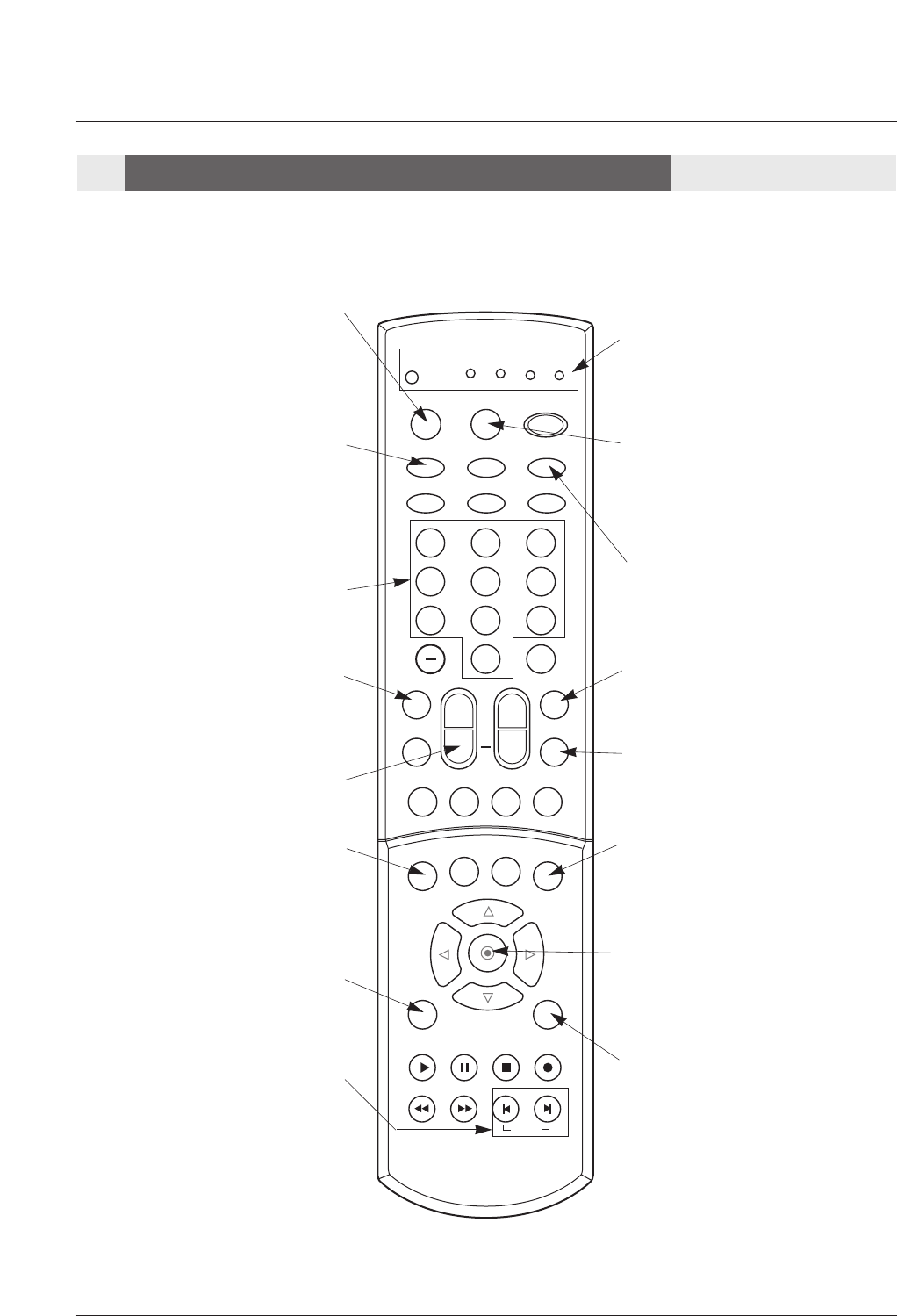
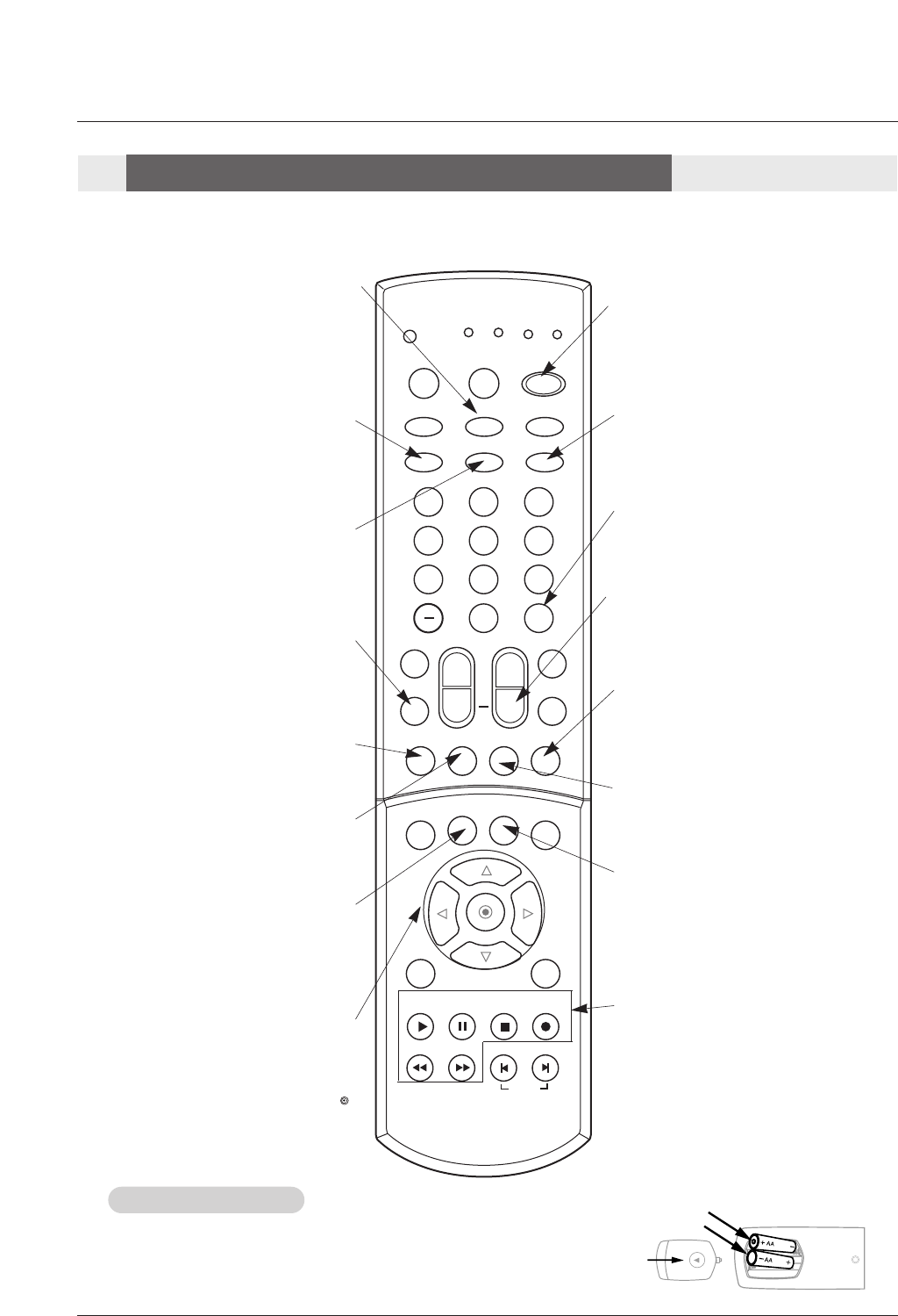
- When using the remote control, aim it at the remote control sensor on the TV.
123
456
789
0
TV
MODE INFO POWER
INPUT EZ PIC
EZ SOUND
VCR
CABLE
DVD HDSTB
MUTE
SWAPPIPCH- PIPCH+
PIP
RATIO
RECORD
STOP
PAUSE
REW
PLAY
FF
MENU EXIT
CC FREEZE
PIP INPUT
VOL CH
FAV
SAP TIMER
SIGNALADJUST
MULTIMEDIA
SKIP
FLASHBK
+
Remote Control Key Functions
Remote Control Key Functions
INDICATOR LIGHTS
Show active remote mode
every time any button is
pressed.
MODE
Selects the remote operating mode:
TV, VCR, Cable, DVD and Satellite.
Select other operating modes, for the
remote to control external devices.
INFO
When you watch the TV, information dis-
plays on top of the screen. Not available
in Component 1-2, RGB, HDMI1/DVI
mode.(Refer to p.?)
INPUT
External input modes rotate in regular
sequence: Antenna, Cable, Av1, Front
Video, Component 1-2, RGB-DTV (or
RGB-PC) and HDMI/DVI input sources.
(Av1, Front Video, Component 1-2 input
sources are linked automatically, only if
these are connected )
FAV
Scrolls the Favorite channels.
EZ PIC
Selects a factory preset picture mode
depending on the viewing environment.
MUTE
Switches the sound on or off.
(Refer to
p.?)
TIMER
Lets you select the amount of time
before your TV turns itself off automati-
cally.
VOLUME UP/DOWN
Increases/decreases the sound level.
NUMBER KEYPAD
For direct channel selection and
programming functions.
RATIO
Changes the screen format or aspect
ratio.
PIP INPUT
Selects the input source for the sub
picture.
ENTER
When in the menu system and other
on-screen displays, selects highlighted
options.
MENU
Brings up the main menu to the
screen.
EXIT
Clears all on-screen displays and returns
to TV viewing from any menu.
SKIP
Playing CDs: Selects songs.
Playing DVDs: Selects movie chapters.
10 Plasma TV
Introduction
123
456
789
0
TV
MODE INFO POWER
INPUT EZ PIC
EZ SOUND
VCR
CABLE
DVD HDSTB
MUTE
SWAPPIPCH- PIPCH+
PIP
RATIO
RECORD
STOP
PAUSE
REW
PLAY
FF
MENU EXIT
CC FREEZE
PIP INPUT
VOL CH
FAV
SAP TIMER
SIGNALADJUST
MULTIMEDIA
SKIP
FLASHBK
+
Remote Control Key Functions
Remote Control Key Functions
• Open the battery compartment cover on the back side and install the batteries
matching correct polarity (+ with +, - with -).
• Install two 1.5V AA batteries. Don’t mix old or used batteries with new ones.
Close cover.
Installing Batteries
Installing Batteries
back of
remote
MULTIMEDIA
Selects: RGB,HDMI/DVI, HDMI2 and
Component input sources.
CC
Selects a closed caption mode for dis-
playing captioning information if avail-
able on program.
POWER
Turns your TV or any other programmed
equipment on or off, depending on mode.
SIGNAL
Displays the digital signal strength.
ADJUST
Adjusts screen position, size, and
phase in PC mode.
EZ SOUND
Selects the sound appropriate for the pro-
gram's character.
SAP
Selects MTS sound: Mono, Stereo, and
SAP in Analog mode. Change the audio
language in DTV mode.
CHANNEL UP/DOWN
Scrolls through available channels in
EZ Scan memory.
FLASHBK
Tunes to the last channel viewed.
PIPCH+
Changes to next higher PIP channel.
SWAP
Exchanges the main/sub images in
PIP/Twin picture mode.
PIPCH-
Changes to next lower PIP channel
PIP
Toggles between PIP and Twin picture
mode.
FREEZE
Freezes the currently-viewed picture.
Main picture is frozen in PIP/Twin picture
mode.
THUMBSTICK
Allows you to navigate the on-screen
menus and to adjust the system settings
and preferences, by moving to an option
with
F G
and selecting the highlighted
option with .
D
E
RECORD, PAUSE, REW, FFWD,
PLAY, STOP
Control the functions on your VCR.
Operating Guide 11
Installation
Owner’s Manual
1.5V
1.5V
Batteries Power Cord
123
456
789
0
TV
MODE INFO POWER
INPUT EZ PIC
EZ SOUND
VCR
CABLE
DVD
HDSTB
MUTE
SWAPPIPCH- PIPCH+
PIP
RATIO
RECORD
STOP
PAUSE
REW
PLAY
FF
MENU EXIT
CC FREEZE
PIP INPUT
VOL CH
FAV
SAP TIMER
SIGNALADJUST
MULTIMEDIA
SKIP
FLASHBK
+
75ΩRound Cable
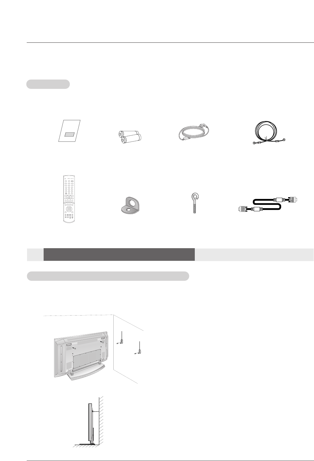
Ensure that the following accessories are included with your plasma display. If an accessory is missing, please contact the dealer
where you purchased the product.
2-Wall brackets 2-eye-bolts
Remote Control
- Secure the TV assembly by joining it to a wall by using the TV/Wall brackets.
- This TV’s stand is sold, separately .
- Here shown may be somewhat different from your TV.
Joining the TV assembly to the wall to protect the set tumbling
•If the set will be mounted on a desk top, insert
the 2 eye-bolts and tighten them securely in the upper
holes as shown.
Install the wall brackets on the wall with 2 bolts*, (not
supplied with the product), as shown.
Match the height of the eye-bolts and the wall brack-
ets.
Check to be sure the eye-bolts and the brackets are
tightened securely.
• Secure the TV assembly to the wall with strong strings
or wire cables, (not supplied with the product), as
shown.
Installation
Installation
Installation Instructions
Installation Instructions
Accessories
Accessories
D-sub 15 pin Cable (RGB)
12 Plasma TV
Installation
GROUNDING
Ensure that you connect the earth ground wire to prevent possible
electric shock. If grounding methods are not possible, have a qualified
electrician install a separate circuit breaker. Do not try to ground the
unit by connecting it to telephone wires, lightening rods, or gas pipes.
TV GUIDE
Power
Supply
Short-circuit
Breaker
4 inches
4 inches
2.36 inches
4 inches
2 inches
TV GUIDE
Desktop Pedestal Installation
Desktop Pedestal Installation
TV GUIDE
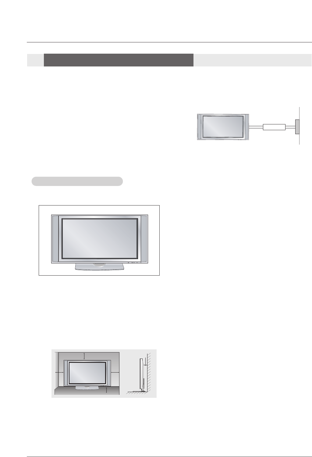
•The TV can be installed in various ways such as on a wall, or on a desktop etc.
•The TV is designed to be mounted horizontally.
Installation Instructions
Installation Instructions
For proper ventilation, allow a clearance of 4” on
each side and the top, 2.36” on the bottom, and
2” from the wall. Detailed installation instructions
are included in the optional Desktop Stand
Installation.
To Install on a Desktop
Pedestal mount minimum
allowableclearances for adequate ventilation.
Operating Guide 13
Installation
External Equipment Connections
External Equipment Connections
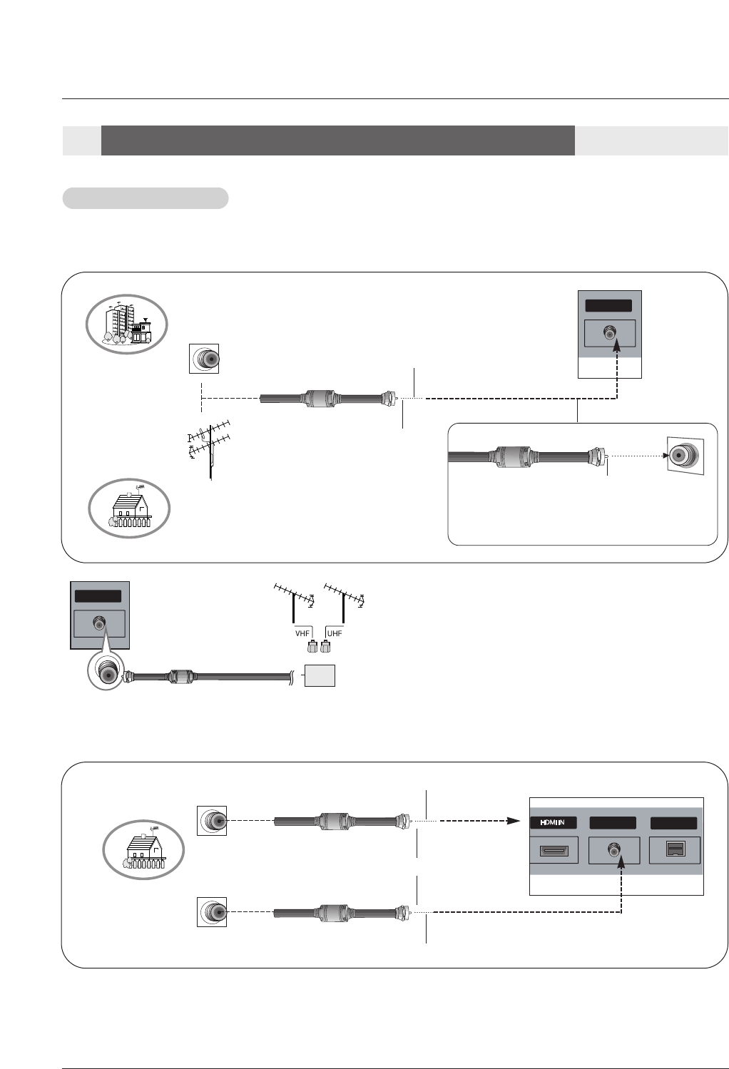
- Antenna or Cable Service without a Cable Box Connections
- For optimum picture quality, adjust antenna direction if needed.
Antenna Connection
Antenna Connection
Analog and Digital TV signals provided on one antenna
NOTE: If you are not sure of the type of signal(s) you are receiving, let EZ Scan complete all the channel signal-type searches.
The TV will let you know when the analog, cable, and digital channel scans are complete.
Analog and DTV signals provided on two separate antennas
•In a poor signal area to improve picture quality, purchase
and install a signal amplifier.
•If the antenna needs to be split for two TV’s, install a “2-
Way Signal Splitter” in the connections.
•If the antenna is not installed properly, contact your deal-
er for assistance.
AUDIO IN(RGB/DVI)
SPEAKER OUT(8 )
SERVICE ONLY
2
ANTENNA
ANTENNA IN
ANTENNA IN M.P.I
L/MONO
R
INTERFACE
RESETRESET UPDATEUPDATE
Multi-family Dwellings/Apartments
(Connect to wall antenna socket)
Single-family Dwellings /Houses
(Connect to wall jack for outdoor antenna)
Outdoor
Antenna
Wall Antenna
Socket
VHF Antenna
UHF Antenna
RF Coaxial Wire (75 ohm)
Copper Wire
Turn clockwise to tighten.
Copper Wire
Be careful not to bend the Copper wire when
connecting the antenna.
AUDIO IN(RGB/DVI)
SPEAKER OUT(8 )
SERVICE ONLY
2
ANTENNA
ANTENNA IN
ANTENNA IN
M.P.I
M.P.I
L/MONO
R
INTERFACE
RESETRESET UPDATEUPDATE
Wall Antenna
Socket RF Coaxial Wire (75 ohm)
Analog Antenna
Digital Antenna
Copper Wire
Copper Wire
Turn clockwise to tighten.
Wall Antenna
Socket RF Coaxial Wire (75 ohm)
AUDIO IN(RGB/DVI)
SPEAKER OUT(8 )
SERVICE ONLY
2
ANTENNA
ANTENNA INANTENNA IN M.P.I
L/MONO
R
INTERFACE
RESETRESET UPDATEUPDATE
Signal
Amplifier
14 Plasma TV
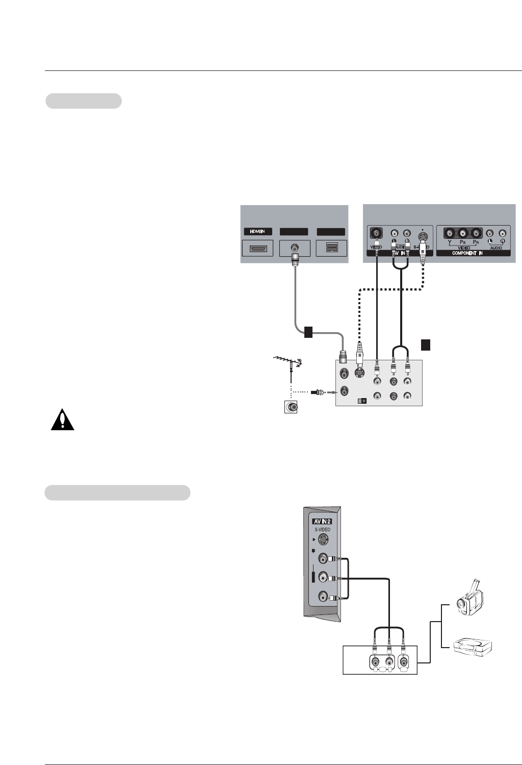
How to connect
Connect the audio and video cables from the external equip-
ment's output jacks to the TV input jacks, as shown in the
figure.
When connecting the TV to external equipment, match the
jack colors (Video = yellow, Audio Left = white, and Audio
Right = red).
How to use
1. Select the input source with using the INPUT button on the
remote control. Note that this TV finds the connected input
sources automatically for Video, Front Video and
Component 1-2. It is presumed that RGB and HDMI/DVI
sources are connected.
2. Operate the corresponding external equipment.
External
External A/V Source Setup
A/V Source Setup
RL
AUDIO VIDEO
L/MONO
MONO
R
AUDIO
VIDEO
Camcorder
Video Game
Device
Installation
- To avoid picture noise (interference), leave an adequate distance between the VCR and TV
- Use the ISM Method (on the Option menu) feature to avoid having a fixed image remain on the screen for a long period of time.
If the 4:3 picture format is used; the fixed images on the sides of the screen may remain visible on the screen.
Connection Option 1
Set VCR output switch to channel 3 or 4 and
then tune the TV to the same channel number.
Connection Option 2
1. Connect the audio and video cables from the
VCR's output jacks to the TV input jacks, as
shown in the figure.
When connecting the TV to VCR, match the
jack colors (Video = yellow, Audio Left = white,
and Audio Right = red).
If you connect an S-VIDEO output from VCR to
the S-VIDEO input, the picture quality is
improved; compared to connecting a regular
VCR to the Video input.
2. Insert a video tape into the VCR and press
PLAY on the VCR. (Refer to the VCR owner’s
manual.)
3. Select the input source with using the INPUT
button on the remote control. Note that this TV
finds the connected input sources automatically
for AV1, Front Video and Component 1-2. It is
presumed that RGB and HDMI/DVI sources are
connected.
Do not connect to both Video and
S-Video at the same time.
VCR Setup
VCR Setup
S-VIDEO OUT
IN
(R) AUDIO (L)
VIDEO
34
OUTPUT
SWITCH
ANT OUT
ANT IN
2
ANTENNA
ANTENNA INANTENNA IN M.P.IM.P.I
VCR Rear
1
2
or
Operating Guide 15
Installation
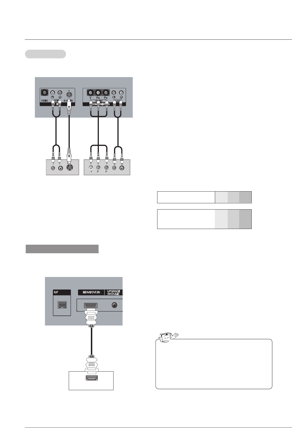
•Component Input ports
To get better picture quality, connect a DVD player to the compo-
nent input ports as shown below.
Component ports
on the TV YPBPR
Video output ports
on DVD player
Y
Y
Y
Y
Pb
B-Y
Cb
PB
Pr
R-Y
Cr
PR
How to connect
1. Connect the DVD video outputs (Y, PB, PR) to the COMPO-
NENT (Y, PB, PR) INPUT jacks on the TV and connect the
DVD audio outputs to the AUDIO INPUT jacks on the TV, as
shown in the figure.
2. If your DVD only has an S-Video output jack, connect this to
the S-VIDEO input on the TV and connect the DVD audio out-
puts to the AUDIO INPUT jacks on the TV, as shown in the
figure.
Note: If your DVD player does not have component video out-
put, use S-Video.
How to use
1. Turn on the DVD player, insert a DVD.
2. Use the INPUT button on the remote control to select
Component 1. (If connected to S-VIDEO, select the AV1 or
Front Video external input source.)
3. Refer to the DVD player's manual for operating instructions.
DVD Setup
DVD Setup
(R) AUDIO (L)
S-VIDEO
BR
(R) AUDIO (L)
INTERFACE
DVD
or
HDMI-DVD OUTPUT
INTERFACEINTERFACE
When supporting HDMI
1. Connect the HDMI output of the DVD to the HDMI/DVI
IN jack on the set.
2. Select HDMI1/DVI or HDMI2 input source with using the
INPUT button on the remote control.
3. Refer to the DVD player's manual for operating instruc-
tions.
•TV can receive the video and audio signal simulta-
neously with using a HDMI cable.
•If the DVD supports Auto HDMI function, the DVD
output resolution will be automatically set to
1280x720p.
•If the DVD does not support Auto HDMI, you need
to set the output resolution appropriately. To get the
best picture quality, adjust the output resolution of
the DVD to 1280x720p.
DVD
16 Plasma TV
Installation
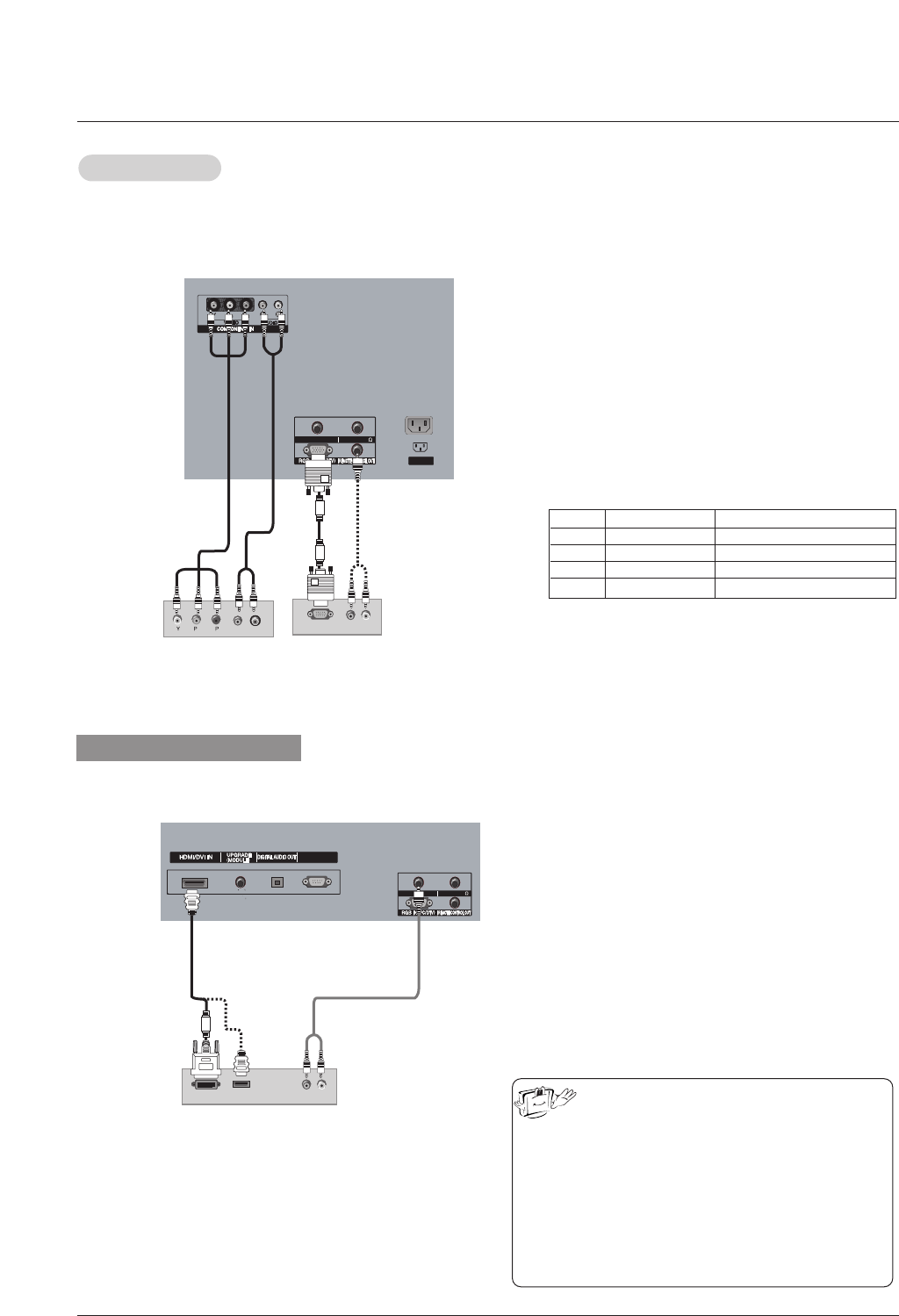
- This TV can receive Digital Over-the-air/Cable signals without an external digital set-top box. However, if you do receive Digital
signals from a digital set-top box or other digital external device, refer to the figure as shown below.
- This TV supports HDCP (High-bandwidth Digital Contents Protection) protocol for Digital Contents (480p,720p,1080i).
How to connect
Use the TV’s COMPONENT (Y, PB, PR) INPUT, RGB or
HDMI/DVI jack for video connections, depending on your
set-top box connector. Then, make the corresponding
audio connections.
How to use
1. Turn on the digital set-top box. (Refer to the owner’s
manual for the digital set-top box.)
2. Use INPUT on the remote control to select Component
1, Component 2, RGB-DTV, or HDMI/DVI source.
HDSTB Setup
HDSTB Setup
Digital Set-top Box
Signal
480i
480p
720p
1080i
Component 1/2
Yes
Yes
Yes
Yes
RGB-DTV , HDMI/DVI
No
Yes
Yes
Yes
or
AUDIO IN(RGB/DVI)
SPEAKER OUT(8 )
SERVICE ONLY
AUDIO IN(RGB/DVI)AUDIO IN(RGB/DVI)
SPEAKER OUT(8 )SPEAKER OUT(8 )
AC INPUT
(R) AUDIO (L)
RGB-DTV OUTPUT
BR
(R) AUDIO (L)
When supporting HDMI
AUDIO IN(RGB/DVI)AUDIO IN(RGB/DVI)
SPEAKER OUT(8 )SPEAKER OUT(8 )
SERVICE ONLYSERVICE ONLY
AUDIO IN(RGB/DVI)
SPEAKER OUT(8 )
(R) AUDIO (L)
DVI-DTV OUTPUT
HDMI-DTV OUTPUT
1. Connect the DVI output of the digital set-top box to the
HDMI /DVI IN or HDMI IN 2 jack on the set.
2. Connect the audio output of the digital set-top box to the
AUDIO IN(RGB/DVI) jack on the set.
3. Turn on the digital set-top box. (Refer to the owner’s
manual for the digital set-top box.)
4. Select HDMI1/DVI or HDMI2 input source with using the
INPUT button on the remote control.
• If the digital set-top box has a DVI output and no
HDMI output, a separated audio connection is nec-
essary.
•If the digital set-top box supports Auto DVI function,
the output resolution of the digital set-top box will be
automatically set to 1280x720p.
•If the digital set-top box does not support Auto DVI,
you need to set the output resolution appropriately.
To get the best picture quality, adjust the output res-
olution of the digital set-top box to 1280x720p.
Operating Guide 17
Installation
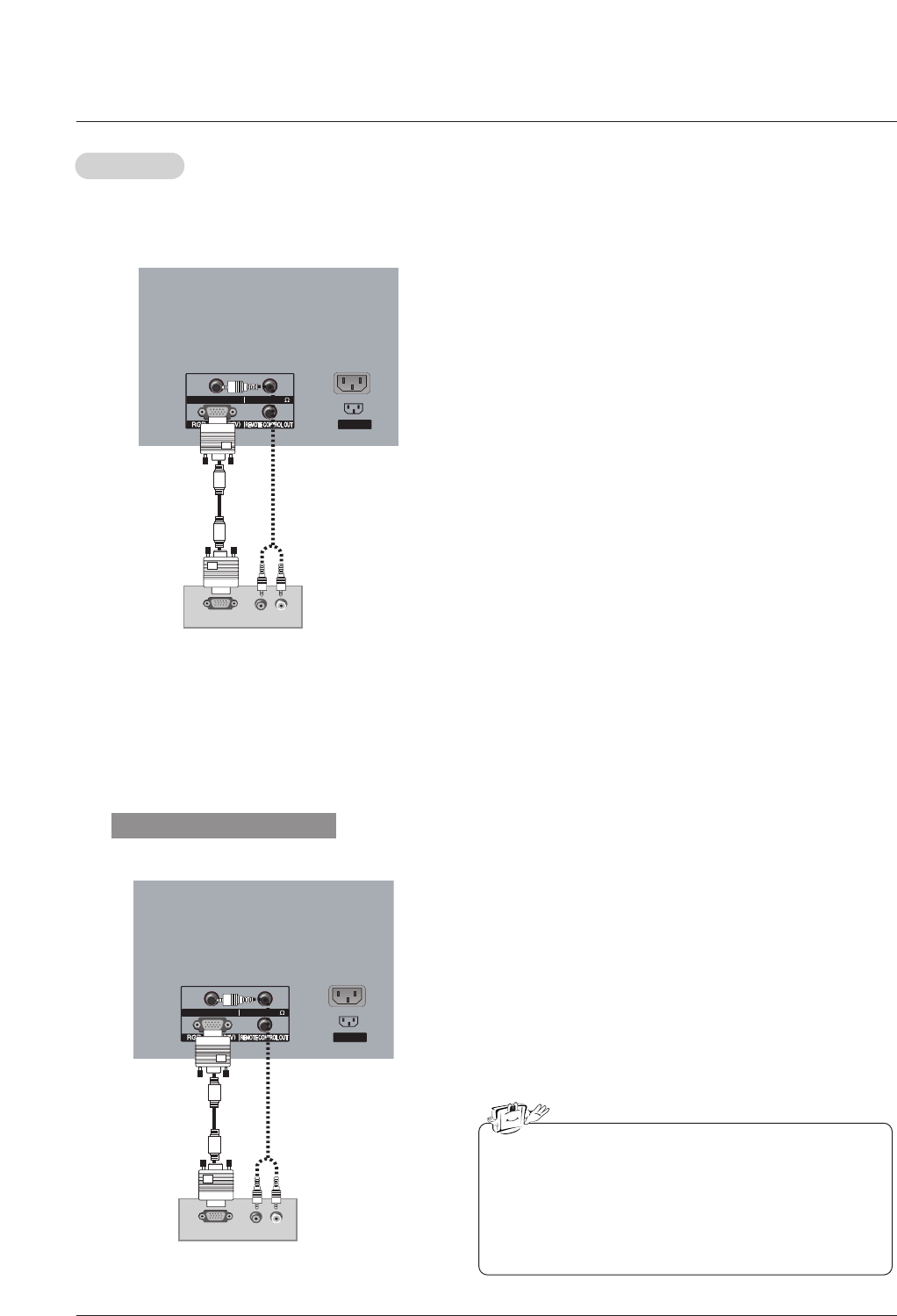
PC Setup
PC Setup
- This TV provides Plug and Play capability, meaning that the PC adjusts automatically to the TV's settings.
- The TV perceives 640x480, 60Hz as DTV 480p based on the PC graphic card, change the screen scanning rate for the graphic
card accordingly.
AUDIO IN(RGB/DVI)
SPEAKER OUT(8 )
SERVICE ONLY
AUDIO IN(RGB/DVI)AUDIO IN(RGB/DVI)
SPEAKER OUT(8 )SPEAKER OUT(8 )
AC INPUT
(R) AUDIO (L)
RGB-PC OUTPUT
AUDIO IN(RGB/DVI)
SPEAKER OUT(8 )
SERVICE ONLY
AUDIO IN(RGB/DVI)AUDIO IN(RGB/DVI)
SPEAKER OUT(8 )SPEAKER OUT(8 )
AC INPUT
(R) AUDIO (L)
RGB-PC OUTPUT
When supporting HDMI
1. Connect the DVI output of the PC to the HDMI/DVI IN{1(DVI)}
jack on the set.
2. Connect the PC audio output to the AUDIO(RGB/DVI) jack
on the set.
3. Turn on the PC and the set.
4. Select HDMI1/DVI input source with using the INPUT button
on the remote control.
• HDMI2 source does not support DVI source.
• If the PC has a DVI output and no HDMI output, a separat-
ed audio connection is necessary.
•If the PC does not support Auto DVI, you need to set the
output resolution appropriately. To get the best picture qual-
ity, adjust the output resolution of PC graphics card's output
resolution to 1024x768, 60Hz.
How to connect
1. To get the best picture quality, adjust the PC graphics card
to 1024x768, 60Hz.
2. Use the TV’s RGB INPUT or DVI (Digital Visual Interface)
INPUT port for video connections, depending on your PC
connector.
• If the graphic card on the PC does not output analog and
digital RGB simultaneously, connect only one of either
RGB INPUT or DVI INPUT to display the PC on the TV.
• If the graphic card on the PC does output analog and digi-
tal RGB simultaneously, set the TV to either RGB or DVI;
(the other mode is set to Plug and Play automatically by
the TV.)
3. Then, make the corresponding audio connections. If using a
sound card, adjust the PC sound as required.
How to use
1. Turn on the PC and the TV.
2. Turn on the display by pressing the POWER button on the
TV's remote control.
3. Select RGB-PC or DVI-PC input source in main input option
of SETUP menu. (Refer to P.23)
4. Check the image on your TV. There may be noise associat-
ed with the resolution, vertical pattern, contrast or brightness
in PC mode. If noise is present, change the PC mode to
another resolution, change the refresh rate to another rate
or adjust the brightness and contrast on the menu until the
picture is clear. If the refresh rate of the PC graphic card
can not be changed, change the PC graphic card or consult
the manufacturer of the PC graphic card.
18 Plasma TV
Installation
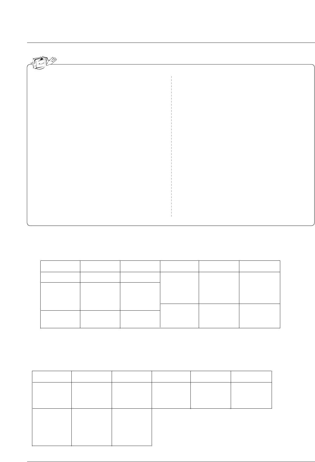
Resolution
640x480
800x600
Horizontal
Frequency(KHz)
31.469
37.861
37.500
35.156
37.879
48.077
46.875
59.94
72.80
75.00
56.25
60.31
72.18
75.00
48.363
56.476
60.023
60.00
70.06
75.02
Vertical
Frequency(Hz) Resolution Horizontal
Frequency(KHz)
Vertical
Frequency(Hz)
1024x768
Monitor Display Specifications (HDMI/DVI Mode)
720x400
800x600
70.08
59.94
72.80
75.00
70.08
35.156
37.879
48.077
46.875
48.363
56.476
60.023
56.25
60.31
72.18
75.00
60.00
70.06
75.02
Vertical
Frequency(Hz) Resolution Horizontal
Frequency(KHz)
Vertical
Frequency(Hz)
1024x768
Resolution
640x480
Horizontal
Frequency(KHz)
31.469
31.469
37.861
37.500
31.469
Monitor Display Specifications (RGB-PC )
640x350
1. Depending on the graphics card, DOS mode may
not work if a HDMI to DVI Cable is in use.
2. When Source Devices connected with HDMI/DVI
Input, output PC Resolution (VGA, SVGA, XGA),
Position and Size may not fit to Screen.Press the
ADJUST button to adjust the screen Position of TV
SET and contact an PC graphics card service cen-
ter.
3 When Source Devices connected with HDMI/DVI
Input, output TV SET Resolution (480p, 720p,
1080i) and TV SET Display fit EIA/CEA-861-B
Specification to Screen. If not, refer to the Manual
of HDMI/DVI Source Devices or contact your ser-
vice center.
4. In case HDMI/DVI Source Devices is not connect-
ed Cable or poor cable connection, "NO SIGNAL"
OSD display in HDMI/DVI Input. In case that Video
Resolution is not supported TV SET output in
HDMI/DVI Source Devices, "INVALID FORMAT"
OSD display. Refer to the Manual of HDMI1/DVI
Source Devices or contact your service center.
5. Check the image on your TV. There may be noise
associated with the resolution, vertical pattern,
contrast or brightness in PC, HDMI/DVI mode. If
noise is present, change the PC or HDMI/DVI
mode to another resolution, change the refresh
rate to another rate or adjust the brightness and
contrast on the menu until the picture is clear. If the
refresh rate of the PC graphic card can not be
changed, change the PC graphic card or consult
the manufacturer of the PC graphic card.
6. Avoid keeping a fixed image on the TV's screen for
a long period of time. The fixed image may become
permanently imprinted on the screen.
7. The synchronization input form for Horizontal and
Vertical frequencies is separate.
Operating Guide 19
Installation
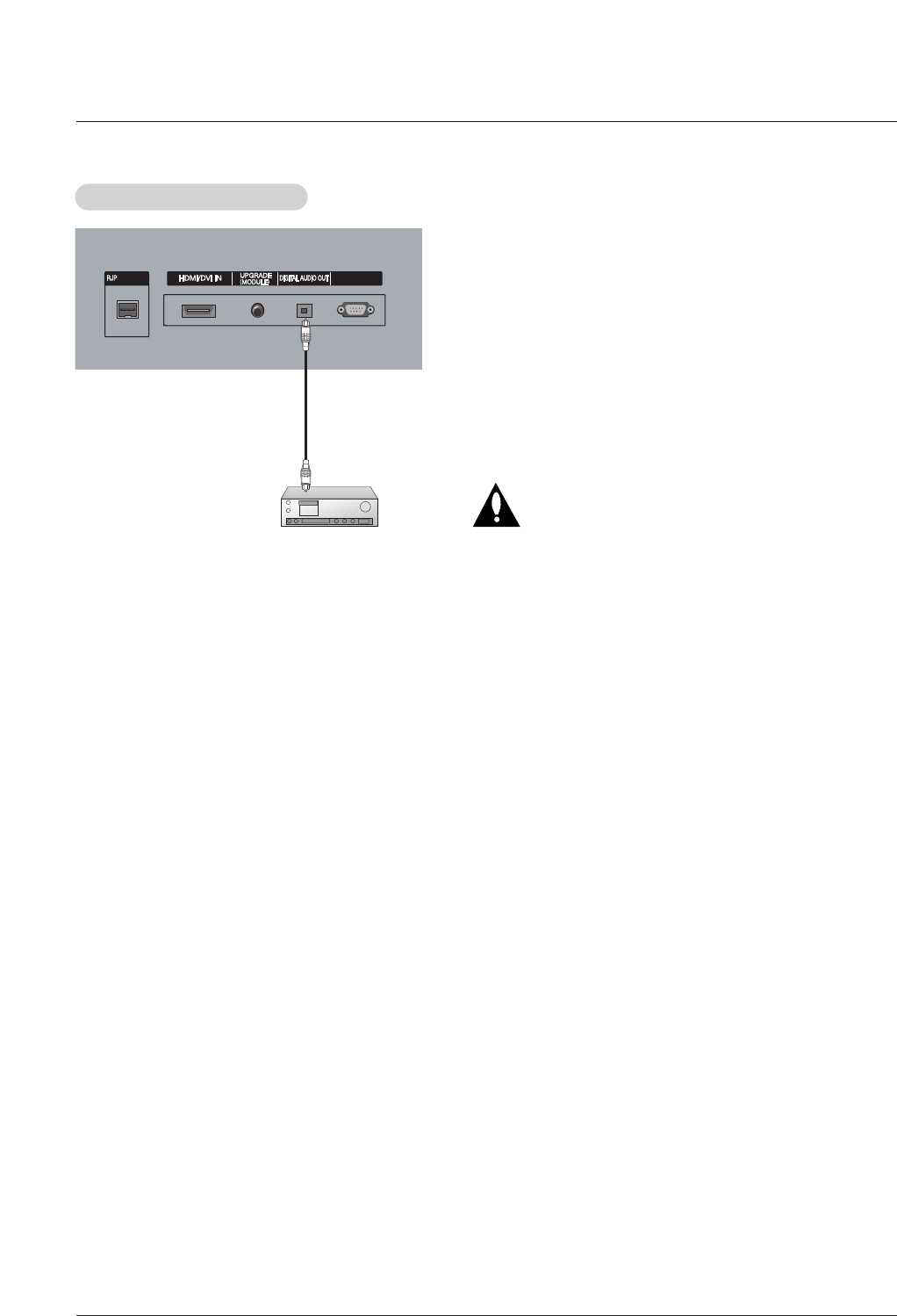
Send the TV’s audio to external audio equipment (stereo system) via
the Digital Audio Output (Optical) port.
How to connect
1. Connect one end of an optical cable to the TV Digital Audio
(Optical) Output port.
2. Connect the other end of the optical cable to the digital audio (opti-
cal) input on the audio equipment.
See the external audio equipment instruction manual for operation.
Note: When connecting with external audio equipments, such as
amplifers or speakers, please turn the TV speakers off.(Refer to
p.28)
Caution: Do not look into the optical output port.
Looking at the laser beam may damage
your vision.
Digital
Digital Audio Output Setup
Audio Output Setup
SERVICE ONLYSERVICE ONLY
INTERFACEINTERFACE
External Audio Equipment

20 Plasma TV
Operation
1. First, connect power cord correctly. At this moment, the TV switches to standby mode.
In standby mode to turn TV on, press the , INPUT , CH (DD/ EE)button on the TV or press the POWER,
TV INPUT, INPUT, CH (DD/ EE), Number (0 ~ 9) button on the remote control.
-The menus can be shown on the screen in the selected language. First select your language.
1. Press the MENU button and then use DD/ EEbutton to select the OPTION
menu.
2. Press the GGbutton and then use DD/ EEbutton to select Language.
3. Press the GGbutton and then use DD/ EEbutton to select your desired language.
From this point on, the on-screen menus will be shown in the selected lan-
guage.
4. Press EXIT button to return to TV viewing or press MENU button to return to
the previous menu.
2. Select the viewing source by using INPUT button on the remote control.
This TV is programmed to remember which power state it was last set to, even if the power cord is out.
3. When finished using the TV, press the POWER button on the remote control. The TV reverts to standby mode.
TV Setup
TV Setup
On-screen Menus Language Selection
On-screen Menus Language Selection
Operation
Operation
T
Turning the TV On
urning the TV On
* In this manual, the OSD (On Screen Display) may be different from your TV’s because it is just an
example to help you with the TV operation.
Operating Guide 21
Operation
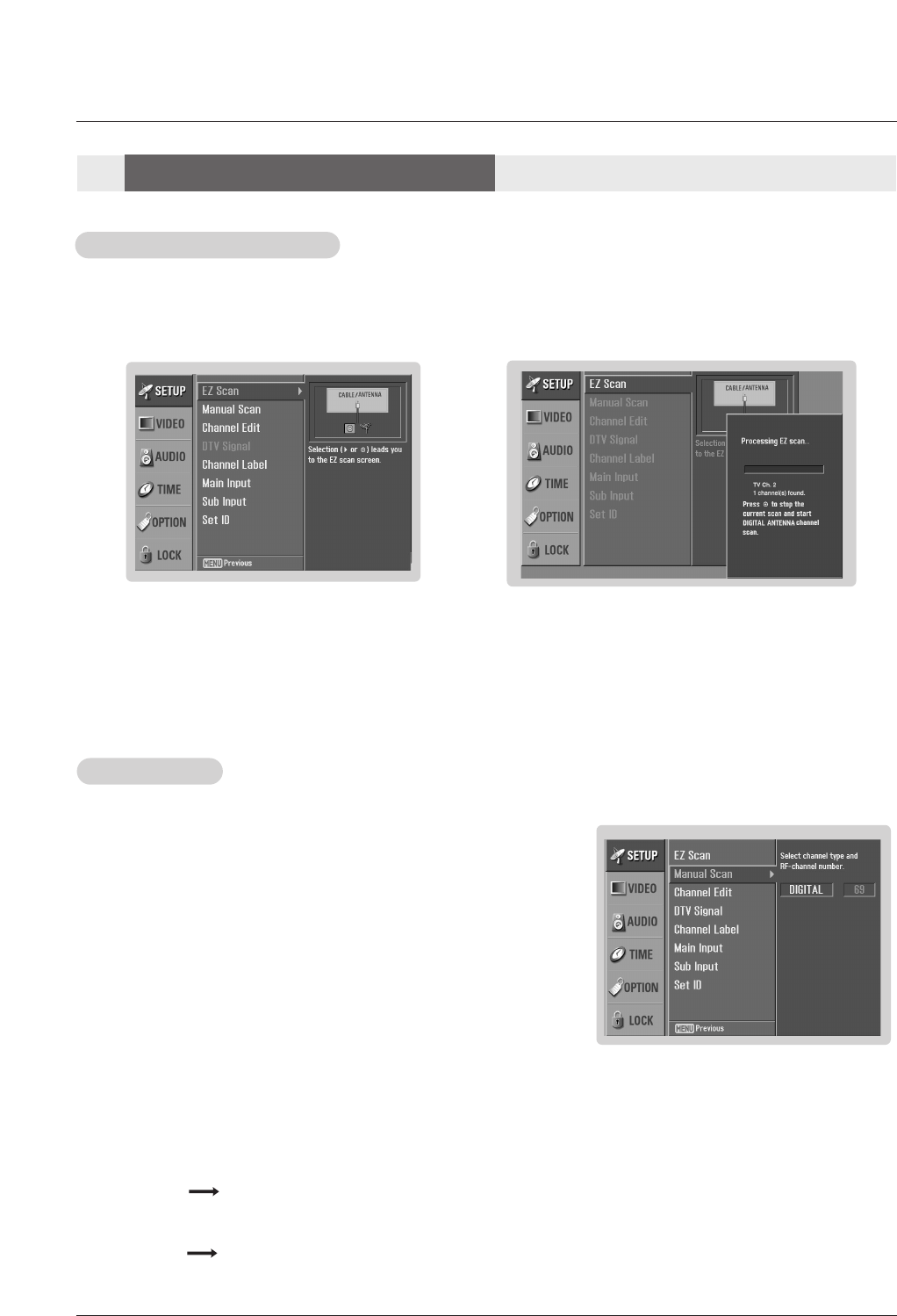
- Automatically finds all available channels through antenna or cable inputs, and stores them in memory on the channel list.
- Run EZ Scan again after any Antenna/Cable connection changes.
- A password is required to gain access to EZ Scan menu if the Lock System is turned on.
1. Press the MENU button and then use DD / EEbutton to select the SETUP menu.
2. Press the GGbutton and then use DD / EEbutton to select EZ Scan.
3. Press the ENTER button to begin the channel search.
Allow EZ Scan to complete the channel search cycle for ANTENNA, and CABLE.
EZ Scan (Channel Search)
EZ Scan (Channel Search)
1. Press the MENU button and then use DD / EEbutton to select the SETUP menu.
2. Press the GGbutton and then use DD / EEbutton to select Manual Scan.
3. Press the GGbutton and then use DD / EEbutton to select DIGITAL and ANALOG.
4. Press the GGbutton and then use DD / EEbutton to select channel number you
want to add or delete.
5. Press the ENTER button to add or delete for the channel number.
6. Press EXIT button to return to TV viewing or press MENU button to return to
the previous menu.
Manual Scan
Manual Scan
Notes:
• This channel number is a physical channel number, which is different from the normal channel number shown in Channel
Edit.
• Antenna jack Analog TV signal
Digital DTV signal
• Cable jack Analog CATV signal
Digital CADTV signal
Setup Menu Options
Setup Menu Options
- A password is required to gain access to Manual Scan menu if the Lock System is turned on.
22 Plasma TV
Operation
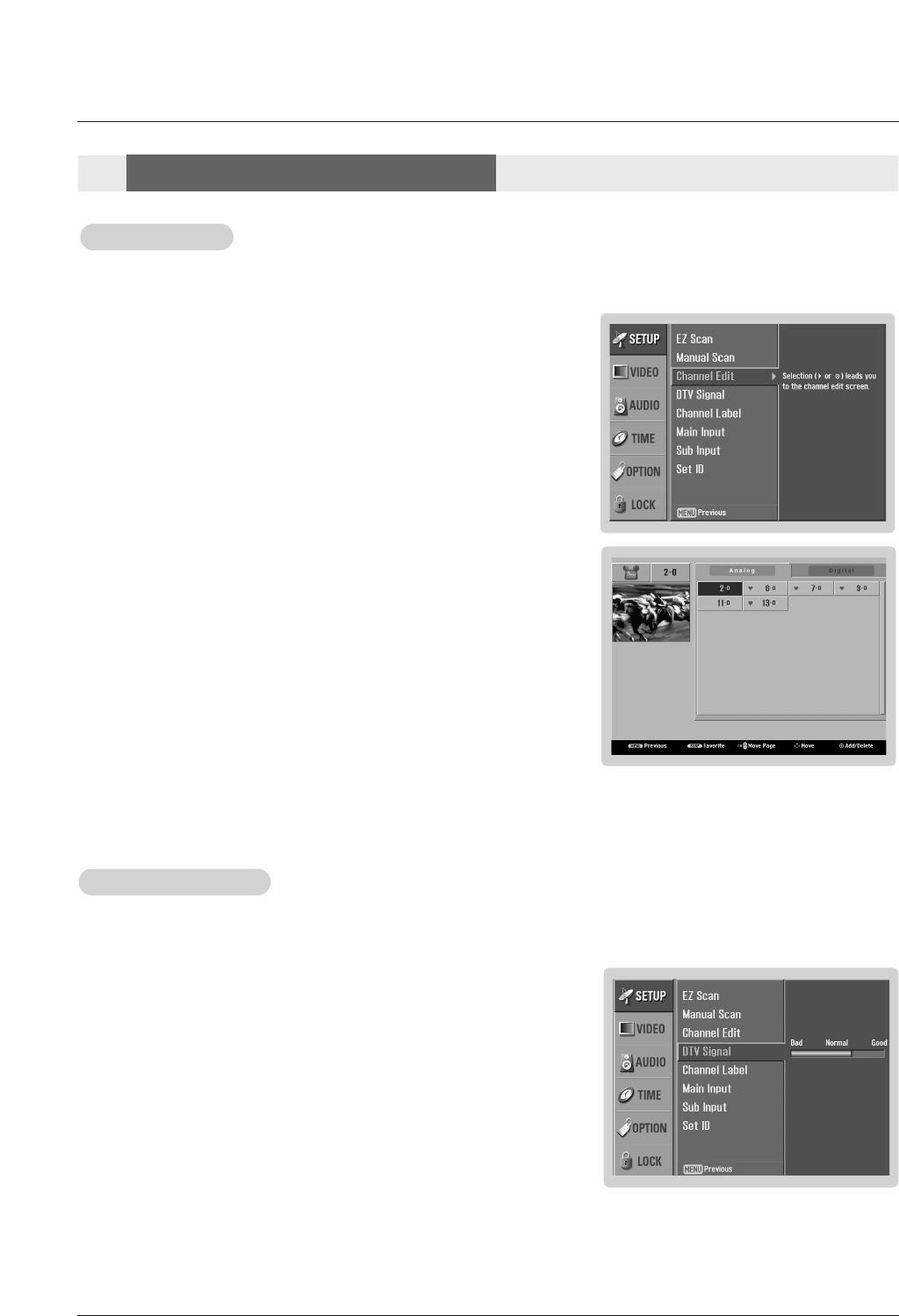
- There are two different ways in order to add or delete scanned channels. One
is "Custom List" and the other is "Favorite List" in the channel list. Both of them
are available after EZ Scan on the SETUP menu.
- A Custom List can be created by toggling each channel on or off with ENTER
button. The channels in the Custom List are displayed in black color, and the
channels deleted from the Custom List are displayed in gray color. Once a
channel is highlighted you can add or delete the channel by referring to the
small window at the top-left corner of the screen.You can create your own
Favorite List. Use the FAV button on the remote control when a channel is
highlighted and then you can add or delete the channel to/from the Favorite
List.
1. Press the MENU button and then use DD / EEbutton to select the SETUP menu.
2. Press the GGbutton and then use DD / EEbutton to select Channel Edit.
3. Press the GGbutton. You will now see a screen filled with channel numbers and
a preview picture.
4. Use DD / EE/ FF / GG button to select a channel and then use the ENTER button to
add or delete it. Press FAV button to add the channel to the Favorite List.
5. Press EXIT button to return to TV viewing or press MENU button to return to the
previous menu.
Channel Edit
Channel Edit
- It indicates strength of the DTV signal whether you need to adjust your antenna or digital cable input.
The higher the signal strength, the less likely you are to experience picture degradation.
- DTV Signal: Only when the input signal is DTV or CADTV, this function is available.
DTV Signal Strength
DTV Signal Strength
1. Press the MENU button and then use DD / EEbutton to select the SETUP menu.
2. Press the GGbutton and then use DD / EEbutton to select DTV Signal.
3. View the on-screen signal strength monitor to see the quality of the signal being
received.
4. Press EXIT button to return to TV viewing or press MENU button to return to the
previous menu.
Setup Menu Options
Setup Menu Options
Operating Guide 23
Operation
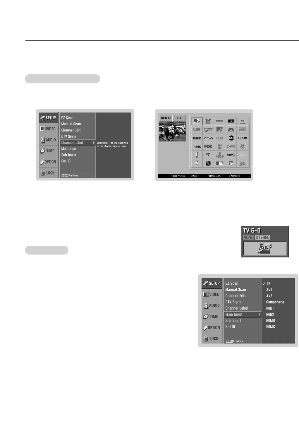
- Change the picture source so you can watch your TV, cable TV, VCR, DVD, or any other devices that are connected to your TV.
1. Press the MENU button and then use DD / EEbutton to select the SETUP menu.
2. Press the GGbutton and then use DD / EEbutton to select Main Input.
3. Press the GGbutton and then use DD / EEbutton to select the source: TV, AV1, AV2,
Component, RGB1, RGB2, HDMI1, HDMI2
4. Press EXIT button to return to TV viewing or press MENU button to return to the
previous menu.
Note:
• To toggle RGB-DTV and RGB-PC, select RGB-DTV(or RGB-PC) and press
GG
button.
Main Input
Main Input
- Choose preset labels for your channels.
- If a channel label is provided on the signal from the broadcasting station, the TV displays a short name for a channel -
even if you didn't preset a label for the channel.
1. Press the MENU button and then use DD / EEbutton to select the SETUP menu.
2. Press the GGbutton and then use DD / EEbutton to select Channel Label.
3. Press the GGbutton. You will now see a screen filled with Labels and a preview screen.
4. Use the CH DD/EEbutton to select a channel to Label.
5. Use DD / EE/ FF / GG button to select the appropriate label for the channel, then press ENTER button to set the Label to
the selected channel.
- If you press ENTER button in TV viewing mode, you will see the channel banner. • For example:
Channel Label Setup
Channel Label Setup
24 Plasma TV
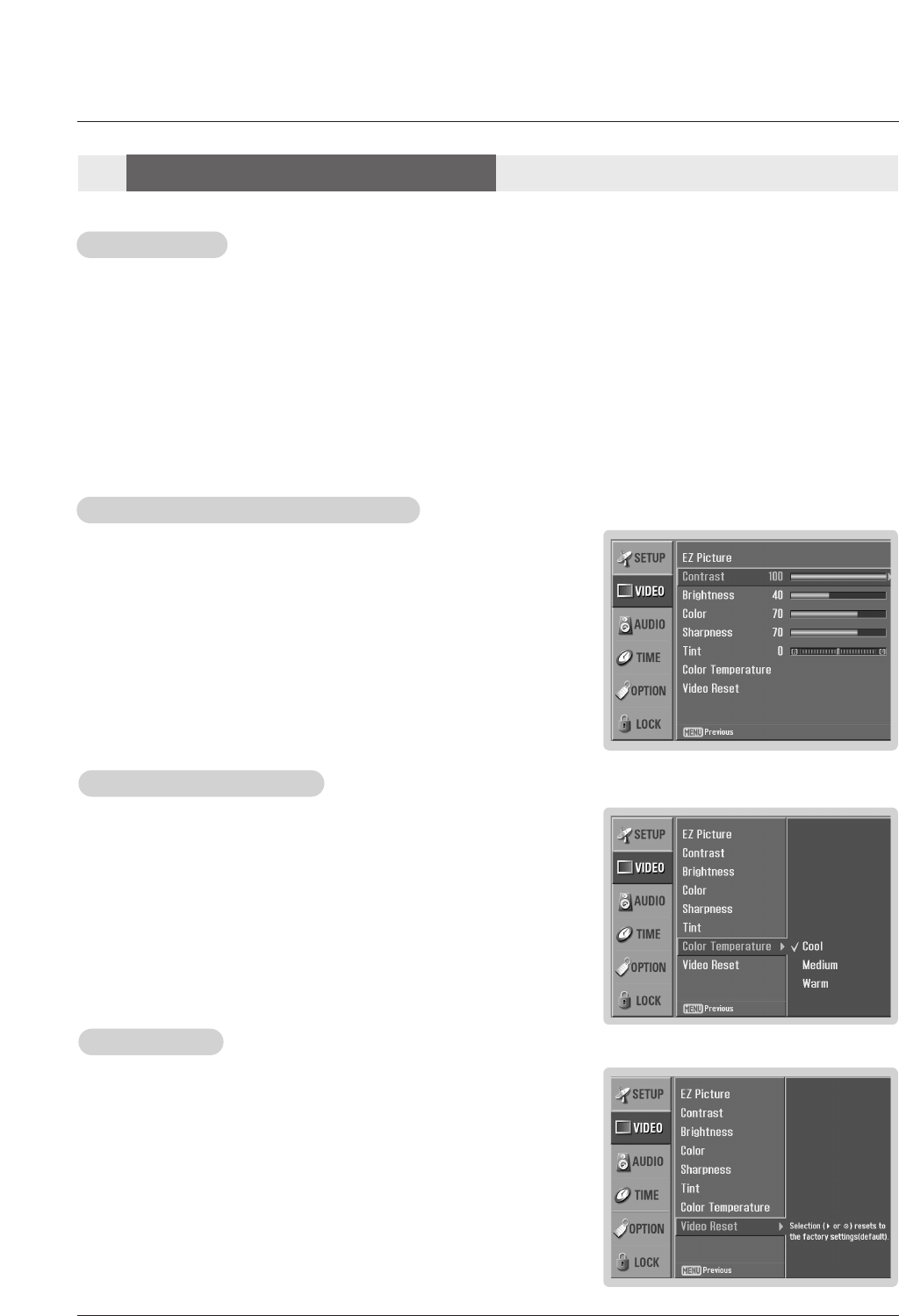
- Use to quickly reset all the Video menu options to their original factory preset
values.
1. Press the MENU button and then use DD / EEbutton to select the VIDEO menu.
2. Press the GGbutton and then use DD / EEbutton to select Video Reset .
3. Press the GGbutton to reset the Video menu options to original values.
V
Video Reset
ideo Reset
Operation
- Adjust the picture appearance to suit your preference and viewing situations.
1. Press the MENU button and then use DD / EEbutton to select the VIDEO menu.
2. Press the GGbutton and then use DD / EEbutton to select the desired picture option
(Contrast,Brightness,Color,Sharpness, or Tint ).
3. Press the GGbutton and then use FF / GGbutton to make appropriate adjustments.
4. Press EXIT button to return to TV viewing or press MENU button to return to the
previous menu.
1. Press the EZ PIC button repeatedly to select the picture appearance setup option as shown below:
Custom (your own settings), Daylight, Normal, Night Time, Movie, Video Game, and Sports.
• You can also use the VIDEO menu to adjust EZ Picture.
2. Press the EXIT button to save and return to TV viewing or press MENU button to return to the previous menu.
EZ Picture
EZ Picture
Manual Picture Control (
Manual Picture Control (Custom option)
option)
- Choose one of three automatic color adjustments. Set to warm to enhance hotter
colors such as red, or set to cool to see less intense colors with more blue.
1. Press the MENU button and then use DD / EEbutton to select the VIDEO menu.
2. Press the GGbutton and then use DD / EEbutton to select Color Temperature .
3. Press the GGbutton and then use DD / EEbutton to select either Cool,Medium or
Warm.
4. Press EXIT button to return to TV viewing or press MENU button to return to the
previous menu.
Color
Color T
Temperature Control
emperature Control
- EZ Picture adjusts the TV for the best picture appearance. Select the preset value in the EZ Picture menu based on the
program category.
- When adjusting Video menu options (contrast, brightness, color, sharpness, tint, and color temperature) manually, EZ
Picture automatically changes to Custom.
-Daylight, Normal, Night Time, Movie, Video Game, and Sports settings are preset for optimum picture quality at
the factory and are not adjustable.
V
Video Menu Options
ideo Menu Options
Operating Guide 25
Operation
- Other languages may be available if a digital signal is provided by the broad-
casting station.
1. Press the EZ SOUND button repeatedly to select the appropriate sound setup as shown below:
Custom (your own settings), Normal, Stadium, News, Music, and Theater.
• You can also adjust EZ Sound in the AUDIO menu.
2. Press EXIT button to save and return to TV viewing or press MENU button to return to the previous
menu.
EZ Sound
EZ Sound
1. Press the MENU button and then use DD / EEbutton to select the AUDIO menu.
2. Press the GGbutton and then use DD / EEbutton to select the desired sound option
(Balance,Treble, or Bass).
3. Press the GGbutton and then use FF / GGbutton to make appropriate adjustments.
4. Press EXIT button to return to TV viewing or press MENU button to return to the
previous menu.
Manual Sound Control (
Manual Sound Control (Custom option)
option)
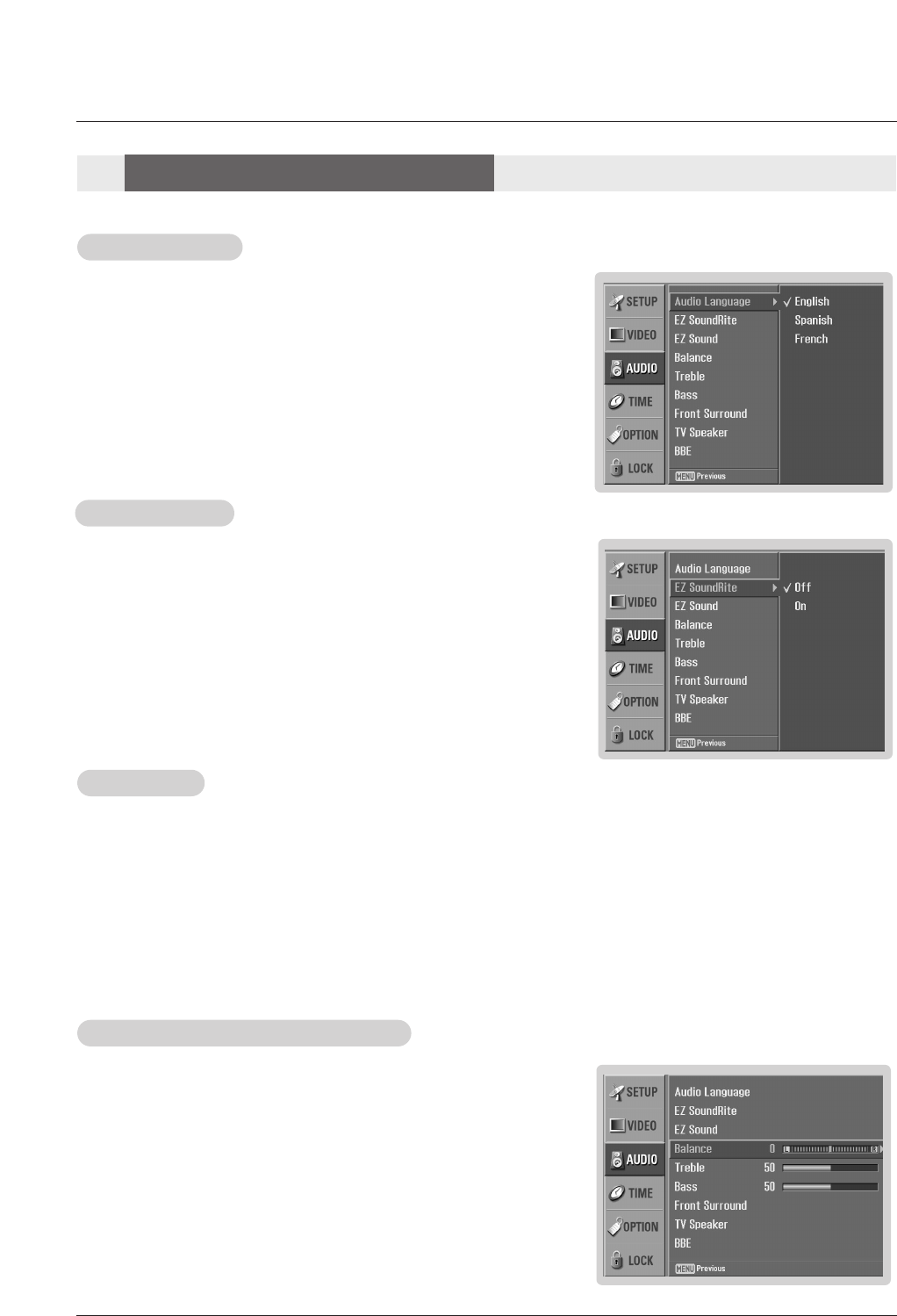
1. Press the MENU button and then use DD / EEbutton to select the AUDIO menu.
2. Press the GGbutton and then use DD / EEbutton to select Audio Language.
3. Press the GGbutton and then use DD / EEbutton to select: English, Spanish, or
French.
4. Press EXIT button to return to TV viewing or press MENU button to return to the
previous menu.
Audio Language
Audio Language
- EZ Sound lets you enjoy the best sound without any special adjustment because the TV sets the appropriate sound
options based on the program content.
- When adjusting sound options (treble, bass, and front surround) manually, EZ Sound automatically switches to Custom.
-Normal, Stadium, News, Music, and Theater are preset for good sound quality at the factory and are not adjustable.
- Scans for changes in sound level during commercials, then adjusts the sound
to match the specified audio level. EZ SoundRite makes sure that the volume
level remains consistent whether you are watching a commercial or a regular
TV program.
1. Press the MENU button and then use DD / EEbutton to select the AUDIO menu.
2. Press the GGbutton and then use DD / EEbutton to select EZ SoundRite.
3. Press the GGbutton and then use DD / EEbutton to select On or Off.
4. Press EXIT button to return to TV viewing or press MENU button to return to the
previous menu.
EZ SoundRite
EZ SoundRite
- Adjust the sound to suit your taste and room situations.
Audio Menu Options
Audio Menu Options
26 Plasma TV
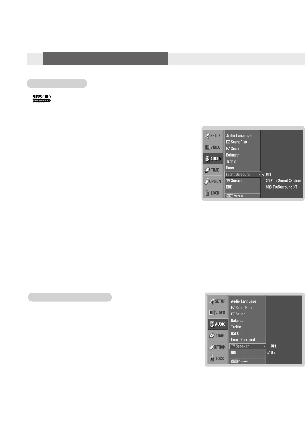
1. Press the MENU button and then use DD / EEbutton to select the AUDIO menu.
2. Press the GGbutton and then use DD / EEbutton to select TV Speaker.
3. Press the GGbutton and then use DD / EEbutton to select On or Off.
4. Press EXIT button to return to TV viewing or press MENU button to return to the
previous menu.
TV Speakers On/Of
TV Speakers On/Off Setup
f Setup
- Turn TV speakers off if using external audio equipment. Feature turns the TV
Speakers option On or Off.
Operation
1. Press the MENU button and then use DD / EEbutton to select the AUDIO menu.
2. Press the GGbutton and then use DD / EEbutton to select Front Surround.
3. Press the GGbutton and then use DD / EEbutton to select Off, 3D EchoSound
System or SRS (Sound Retrieval System) TruSurround XT..
• 3D EchoSound System
Creates a stunning simulated stereo effects from any mono sound and a
realistic three-dimensional sound with a very wide and deep sound stage
into stereo sound.
• SRS TruSurround XT
Takes advantage of any multi-channel format without needing to add extra
speakers or equipment. Dialog clarity, bass enrichment, and the addition of
stereo audio enhancement that produces an immersive sound experience
from standard stereo material.
4. Press EXIT button to return to TV viewing or press MENU button to return to
the previous menu.
Front Surround
Front Surround
- is a trademark of SRS Labs, Inc.
- TruSurround XT technology is incorporated under license from SRS Labs, Inc.
- Manufactured under license from Dolby Laboratories. “Dolby” and the double-D symbol are trademarks of Dolby Laboratories.
Audio Menu Options
Audio Menu Options
Operating Guide 27
Operation
1. Use the SAP button to select your desired MTS mode in a analog signal. Each time you press the SAP button, Mono,
Stereo, or SAP appear in turn.
• If other languages are available on the digital signal, select them with the SAP button.
2. Press EXIT button to save and return to TV viewing.
Stereo/SAP
Stereo/SAP Broadcasts Setup
Broadcasts Setup
- This TV can receive MTS stereo programs and any SAP (Secondary Audio Program) that accompanies the stereo program;
if the station transmits an additional sound signal as well as the original one.
- When having selected Stereo or SAP button on the remote control, this TV can only receive the signal when the TV station
transmits the proper signals.
- Mono sound is automatically received if the broadcast is only in Mono; even though Stereo or SAP has been selected.
- Select Mono if you want to listen to mono sound during stereo/SAP broadcasting.
- Stereo or SAP can be received in a Analog channel.
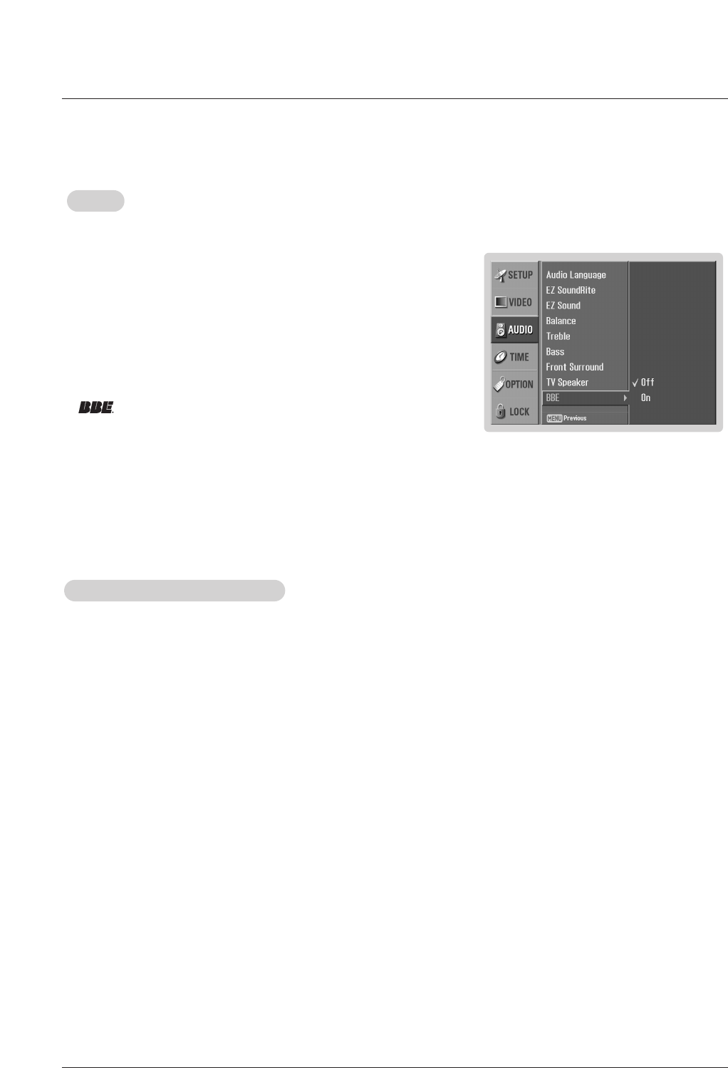
1. Press the MENU button and then use DD / EEbutton to select the AUDIO menu.
2. Press the GGbutton and then use DD / EEbutton to select BBE.
3. Press the GGbutton and then use DD / EEbutton to select On or Off.
4. Press EXIT button to return to TV viewing or press MENU button to return to
the previous menu.
BBE
BBE
- BBE High Definition Sound restores clarity and presence for better speech
intelligibility and music realism.
•Manufactured under license from BBE Sound, Inc.
•Treble, Bass or BBE aren’t suitable for SRS TSXT mode.
28 Plasma TV
Operation
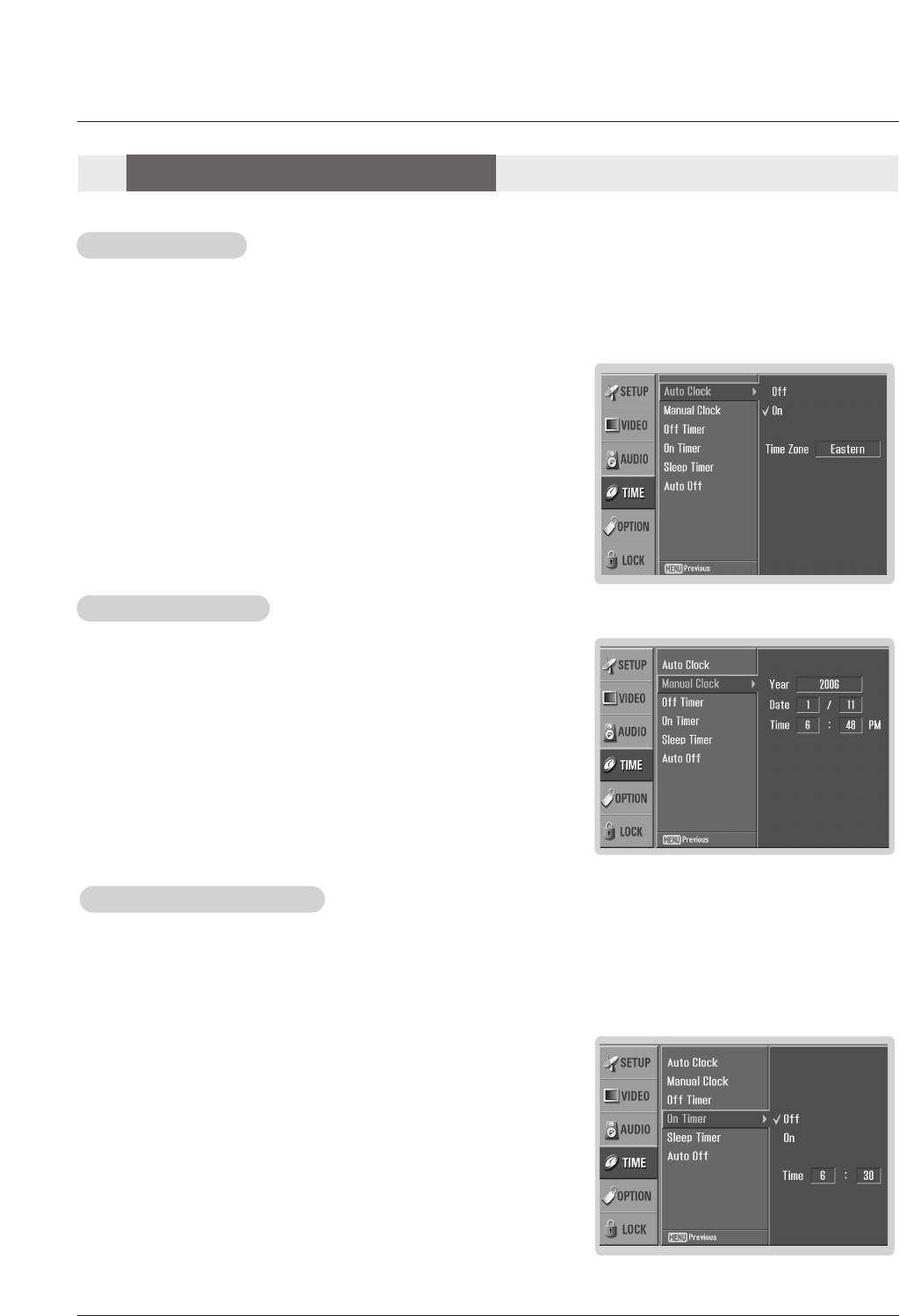
- Timer function operates only if the current time has been set.
- Off-Timer function overrides On-Timer function if they are both set to the same time.
- The TV must be in standby mode for the On-Timer to work.
- If you do not press any button within 2 hours after the TV turns on with the On Timer function, the TV will automatically revert to
standby mode.
On/Of
On/Off
f T
Timer Setup
imer Setup
1. Press the MENU button and then use DD / EEbutton to select the TIME menu.
2. Press the GGbutton and then use DD / EEbutton to select Off Timer or On Timer.
3. Press the GGbutton and then use DD / EEbutton to select On.
• To cancel On/Off timer function, select Off.
4. Press the GGbutton and then use DD / EEbutton to set the hour.
5. Press the GGbutton and then use DD / EEbutton to set the minutes.
6. For only On timer function
Press the GGbutton and then use DD / EEbutton to select the channel at turn-on.
Press the GGbutton and then use DD / EEbutton to set the sound level at turn-on.
7. Press EXIT button to return to TV viewing or press MENU button to return to the
previous menu.
Auto Clock Setup
Auto Clock Setup
- The time is set automatically from a digital channel signal.
- The digital channel signal includes information for the current time provided by the broadcasting station.
- Set the clock manually, if the current time is set incorrectly by the auto clock function.
1. Press the MENU button and then use DD / EEbutton to select the TIME menu.
2. Press the GGbutton and then use DD / EEbutton to select Auto Clock.
3. Press the GGbutton and then use DD / EEbutton to select On or Off.
4. Press the GGbutton and then use DD / EEbutton to select your viewing area time
zone: Eastern, Central, Mountain, Pacific, Alaska, or Hawaii.
5. Press EXIT button to return to TV viewing or press MENU button to return to
the previous menu.
Manual Clock Setup
Manual Clock Setup
- If current time setting is wrong, reset the clock manually.
1. Press the MENU button and then use DD / EEbutton to select the TIME menu.
2. Press the GGbutton and then use DD / EEbutton to select Manual Clock.
3. Press the GGbutton and then use FF / GGbutton to select either the year, date,
or time option. Once selected, use the DD / EEbutton to set the year, date, and
time options.
4. Press EXIT button to return to TV viewing or press MENU button to return to
the previous menu.
T
Time Menu Options
ime Menu Options