LG Electronics USA 47LB5DFUL LCD TV/MONITOR User Manual 1 LB5DF SAC30708011 Edit1 en
LG Electronics USA LCD TV/MONITOR 1 LB5DF SAC30708011 Edit1 en
Contents
- 1. Users manual 1
- 2. Users manual 2
Users manual 1
Please read this manual carefully before operating
your set.
Retain it for future reference.
Record model number and serial number of the set.
See the label attached on the back cover and quote
this information to your dealer
when you require service.
LCD TV PLASMA TV
OWNER’S MANUAL
LCD TV MODELS
37LB5D
42LB5D
47LB5D
52LB5D
47LC7DF
PLASMA TV MODELS
50PY3D
60PY3D
www.lgusa.com / www.lg.ca
As an ENERGY STAR
Partner LGE U. S. A.,Inc.
has determined that this
product meets the
ENERGY STAR guidelines
for energy efficiency.
ENERGY STAR is a set of power-saving
guidelines issued by the U.S.
Environmental Protection Agency(EPA).
is a trademark of SRS Labs, Inc.
TruSurround XT technology is incorporated under
license from SRS Labs, Inc.
LG TV with this logo displays Full HD(high-defini-
tion) 1080p native resolution by receiving and pro-
cessing a Full HD 1080p signal.
LG TV with this logo can play MP3 music from a
MP3 player, such as iPOD, and JPEG images from a
digital camera through the USB device.
With HDMI CEC support of LG’s audio/video device
connected to the HDMI (high-definition multimedia
interface), LG TV with this logo works easily with one
remote control.
It has three HDMI ports that connect audio and
video devices with one cable and produces the high-
est quality digital images and sound.
TruSurround XT
Manufactured under license from Dolby Laboratories.
“
Dolby
“and the double-D symbol are trademarks of
Dolby Laboratories.
High-definition television. High-resolution digital
television broadcast and playback system composed
of roughly a million or more pixels, 16:9 aspect-ratio
screens, and AC3 digital audio. A subset of digital
television, HDTV formats include 1080i and 720p
resolutions.
LG's own special digital image generator, consisting
of a full digital image processor, six different main
picture quality factors.
R
TruSurround XT
1
WARNING / CAUTION
WARNING / CAUTION
To prevent fire or shock hazards, do not expose
this product to rain or moisture.
FCC NOTICE
Class B digital device
This equipment has been tested and found to comply
with the limits for a Class B digital device, pursuant to
Part 15 of the FCC Rules. These limits are designed
to provide reasonable protection against harmful
interference in a residential installation. This equipment
generates, uses and can radiate radio frequency energy
and, if not installed and used in accordance with the
instructions, may cause harmful interference to radio
communications. However, there is no guarantee that
interference will not occur in a particular installation.
If this equipment does cause harmful interference to
radio or television reception, which can be determined
by turning the equipment off and on, the user is
encouraged to try to correct the interference by one
or more of the following measures:
- Reorient or relocate the receiving antenna.
- Increase the separation between the equipment and
receiver.
- Connect the equipment to an outlet on a circuit
different from that to which the receiver is connected.
- Consult the dealer or an experienced radio/TV
technician for help.
Any changes or modifications not expressly approved
by the party responsible for compliance could void
the user’s authority to operate the equipment.
CAUTION
Do not attempt to modify this product in any way
without written authorization from LG Electronics.
Unauthorized modification could void the user’s
authority to operate this product
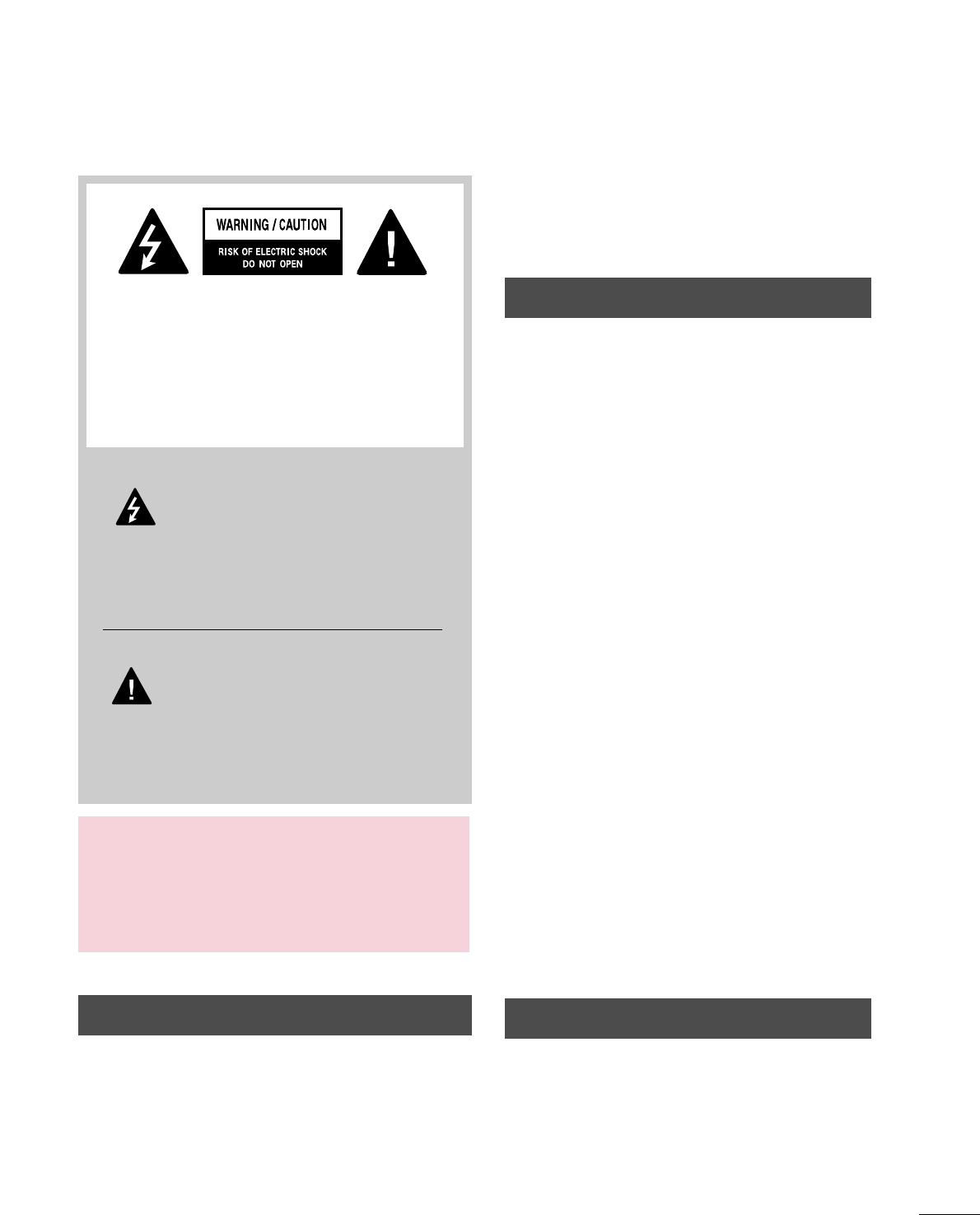
The lightning flash with arrowhead
symbol, within an equilateral triangle, is
intended to alert the user to the presence
of uninsulated “dangerous voltage” within the
product’s enclosure that may be of sufficient
magnitude to constitute a risk of electric shock to
persons.
The exclamation point within an equilateral
triangle is intended to alert the user to
the presence of important operating and
maintenance (servicing) instructions in the litera-
ture accompanying the appliance.
TO REDUCE THE RISK OF ELECTRIC SHOCK
DO NOT REMOVE COVER (OR BACK). NO
USER SERVICEABLE PARTS INSIDE. REFER TO
QUALIFIED SERVICE PERSONNEL.
WARNING/CAUTION
TO REDUCE THE RISK OF FIRE AND ELECTRIC
SHOCK, DO NOT EXPOSE THIS PRODUCT TO
RAIN OR MOISTURE.
NOTE TO CABLE/TV INSTALLER
This reminder is provided to call the CATV system
installer’s attention to Article 820-40 of the National
Electric Code (U.S.A.). The code provides guidelines for
proper grounding and, in particular, specifies that the
cable ground shall be connected to the grounding system
of the building, as close to the point of the cable entry
as practical.
2
IMPORTANT SAFETY INSTRUCTIONS
SAFETY INSTRUCTIONS
Important safety instructions shall be provided with each apparatus. This information shall be given in a separate
booklet or sheet, or be located before any operating instructions in an instruction for installation for use and
supplied with the apparatus.
This information shall be given in a language acceptable to the country where the apparatus is intended to be used.
The important safety instructions shall be entitled “Important Safety Instructions”. The following safety
instructions shall be included where applicable, and, when used, shall be verbatim as follows. Additional safety
information may be included by adding statements after the end of the following safety instruction list. At the
manufacturer’s option, a picture or drawing that illustrates the intent of a specific safety instruction may be
placed immediately adjacent to that safety instruction:
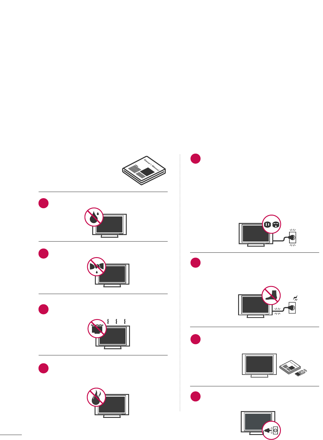
Read these instructions.
Keep these instructions.
Heed all warnings.
Follow all instructions.
Do not use this apparatus near water.
Clean only with dry cloth.
Do not block any ventilation openings. Install in
accordance with the manufacturer’s instructions.
Do not install near any heat sources such as
radiators, heat registers, stoves, or other apparatus
(including amplifiers)that produce heat.
Do not defeat the safety purpose of the polarized
or grounding-type plug. A polarized plug has
two blades with one wider than the other. A
grounding type plug has two blades and a third
grounding prong, The wide blade or the third
prong are provided for your safety. If the provided
plug does not fit into your outlet, consult an
electrician for replacement of the obsolete outlet.
Protect the power cord from being walked on
or pinched particularly at plugs, convenience
receptacles, and the point where they exit from
the apparatus.
Only use attachments/accessories specified by
the manufacturer.
Unplug this apparatus when unused for long
periods of time.
1
2
3
4
5
6
7
8
3
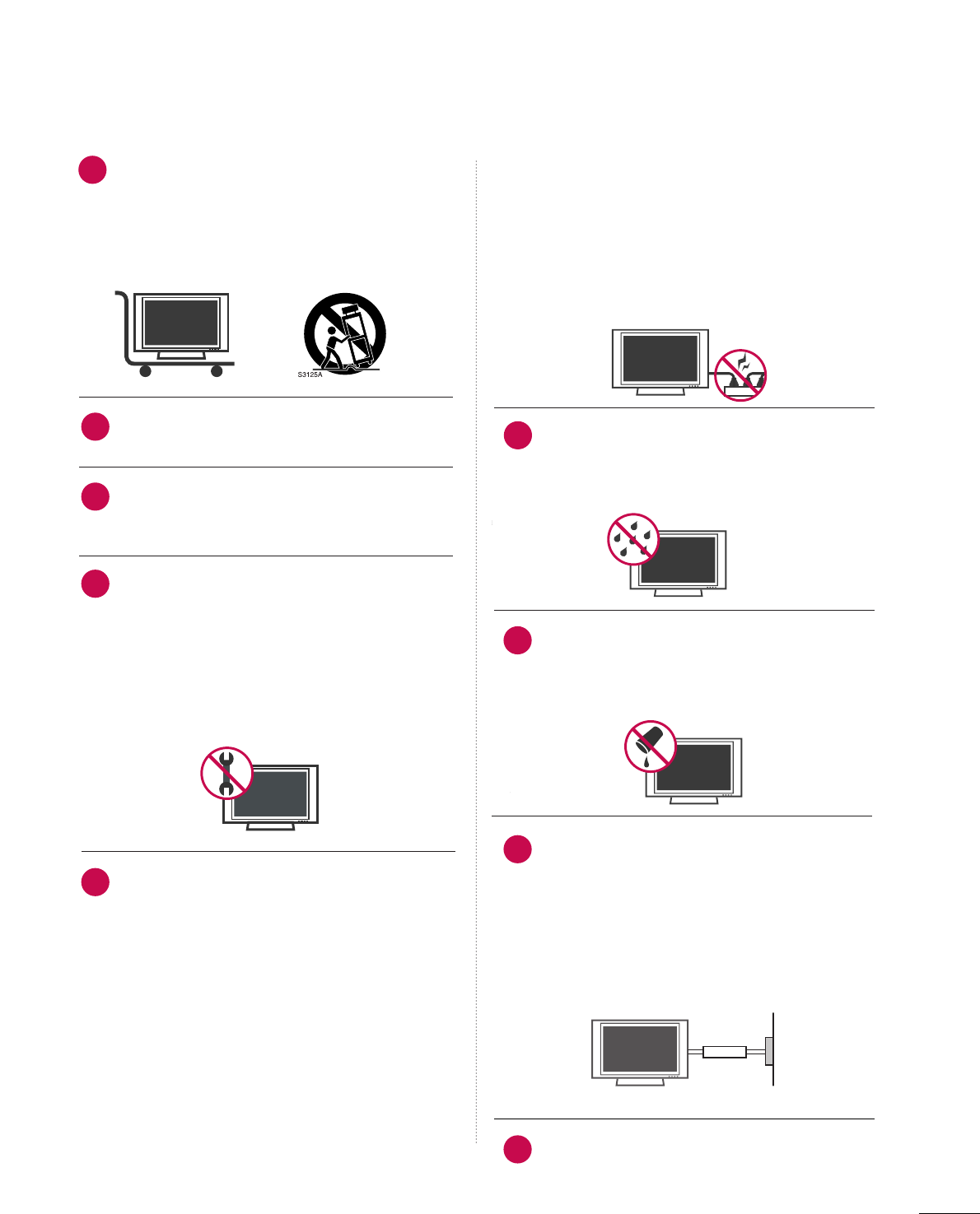
Use only with the cart, stand, tripod, bracket,
or table specified by the manufacturer, or sold
with the apparatus. When a cart is used, use
caution when moving the cart/apparatus
combination to avoid injury from tip-over.
Never touch this apparatus or antenna during
a thunder or lighting storm.
Do not allow a impact shock or any objects to
fall into the product, and do not drop onto the
screen with something.
Refer all servicing to qualified service personnel.
Servicing is required when the apparatus has
been damaged in any way, such as power-supply
cord or plug is damaged, liquid has been
spilled or objects have fallen into the apparatus,
the apparatus has exposed to rain or moisture,
does not operate normally, or has been
dropped.
CAUTION concerning the Power Cord :
Most appliances recommend they be placed
upon a dedicated circuit; that is, a single outlet
circuit which powers only that appliance and
has no additional outlets or branch circuits.
Check the specification page of this owner's
manual to be certain.
Do not overload wall outlets. Overloaded wall
outlets, loose or damaged wall outlets, extension
cords, frayed power cords, or damaged or
cracked wire insulation are dangerous. Any of
these conditions could result in electric shock
or fire. Periodically examine the cord of your
appliance, and if its appearance indicates dam-
age or deterioration, unplug it, discontinue use
of the appliance, and have the cord replaced
with an exact replacement part by an authorized
servicer. Protect the power cord from physical
or mechanical abuse, such as being twisted,
kinked, pinched, closed in a door, or walked
upon. Pay particular attention to plugs, wall
outlets, and the point where the cord exits the
appliance.
Outdoor use marking :
WARNING - To reduce the risk of fire or elec-
tric shock, do not expose this appliance to rain
or moisture.
Wet Location Marking : Apparatus shall not be
exposed to dripping or splashing and no
objects filled with liquids, such as vases, shall
be placed on or over apparatus.
GGRROOUUNNDDIINNGG
Ensure that you connect the earth ground wire
to prevent possible electric shock. If grounding
methods are not possible, have a qualified
electrician install a separate circuit breaker.
Do not try to ground the unit by connecting it
to telephone wires, lightening rods, or gas pipes.
DDIISSCCOONNNNEECCTTIINNGG DDEEVVIICCEE FFRROOMM MMAAIINNSS
Mains plug is the disconnecting device. The
plug must remain readily operable.
Owner Ma nual
Owne r Ma nual
9
12
10
11
13
14
15
16
17
Power
Supply
Short-circuit
Breaker

4
CONTENTS
WARNING / CAUTION
. . . . . . . . . . . . . . . . . . . . . . . . . . . . 1
SAFETY INSTRUCTIONS
. . . . . . . . . . . . . . . . . . . . . . . . . . 2
FEATURE OF THIS TV
. . . . . . . . . . . . . . . . . . . . . . . . . . . . . . . 6
PREPARATION
Accessories . . . . . . . . . . . . . . . . . . . . . . . . . . . . . . . . . . . . . . . . . . . . . . . . . . . . . . 7
Front Panel Information . . . . . . . . . . . . . . . . . . . . . . . . . . . . . . . . . . . . . 8
Back Panel Information . . . . . . . . . . . . . . . . . . . . . . . . . . . . . . . . . . . . 10
Stand Installation . . . . . . . . . . . . . . . . . . . . . . . . . . . . . . . . . . . . . . . . . . . . 12
Not using the desk-type stand . . . . . . . . . . . . . . . . . . . . . . . . 13
Swivel Stand . . . . . . . . . . . . . . . . . . . . . . . . . . . . . . . . . . . . . . . . . . . . . . . . . . . . 13
Back Cover for Wire Arrangement . . . . . . . . . . . . . . . . . . . . . 14
Attaching the TV to a Wall . . . . . . . . . . . . . . . . . . . . . . . . . . . . . . . 16
Desktop Pedestal Installation . . . . . . . . . . . . . . . . . . . . . . . . . . . . 17
VESA Wall Mounting . . . . . . . . . . . . . . . . . . . . . . . . . . . . . . . . . . . . . . . . 18
Antenna or Cable Connection . . . . . . . . . . . . . . . . . . . . . . . . . . 19
EXTERNAL EQUIPMENT SETUP
HD Receiver Setup . . . . . . . . . . . . . . . . . . . . . . . . . . . . . . . . . . . . . . . . . 20
DVD Setup . . . . . . . . . . . . . . . . . . . . . . . . . . . . . . . . . . . . . . . . . . . . . . . . . . . . . 23
VCR Setup . . . . . . . . . . . . . . . . . . . . . . . . . . . . . . . . . . . . . . . . . . . . . . . . . . . . . 25
Other A/V Source Setup . . . . . . . . . . . . . . . . . . . . . . . . . . . . . . . . . 27
PC Setup . . . . . . . . . . . . . . . . . . . . . . . . . . . . . . . . . . . . . . . . . . . . . . . . . . . . . . . . 28
USB In Setup . . . . . . . . . . . . . . . . . . . . . . . . . . . . . . . . . . . . . . . . . . . . . . . . . 34
Audio Out Setup . . . . . . . . . . . . . . . . . . . . . . . . . . . . . . . . . . . . . . . . . . . . 35
WATCHING TV / CHANNEL CONTROL
Remote Control Key Functions . . . . . . . . . . . . . . . . . . . . . . . . . 36
Turning On TV . . . . . . . . . . . . . . . . . . . . . . . . . . . . . . . . . . . . . . . . . . . . . . . . 38
Channel Selection . . . . . . . . . . . . . . . . . . . . . . . . . . . . . . . . . . . . . . . . . . . 38
Volume Adjustment . . . . . . . . . . . . . . . . . . . . . . . . . . . . . . . . . . . . . . . . . 38
On-Screen Menus Selection . . . . . . . . . . . . . . . . . . . . . . . . . . . . . 39
Channel Setup
- Auto Scan (Auto Tuning) . . . . . . . . . . . . . . . . . . . . . . . . . . . 40
- Add / Delete Channel (Manual Tuning) . . . . . . 41
- Channel Editing . . . . . . . . . . . . . . . . . . . . . . . . . . . . . . . . . . . . . . . . 42
Input List . . . . . . . . . . . . . . . . . . . . . . . . . . . . . . . . . . . . . . . . . . . . . . . . . . . . . . . . 43
SimpLink . . . . . . . . . . . . . . . . . . . . . . . . . . . . . . . . . . . . . . . . . . . . . . . . . . . . . . . . . 44
Input Label . . . . . . . . . . . . . . . . . . . . . . . . . . . . . . . . . . . . . . . . . . . . . . . . . . . . . 46
Key Lock . . . . . . . . . . . . . . . . . . . . . . . . . . . . . . . . . . . . . . . . . . . . . . . . . . . . . . . . . 47
Entry Modes . . . . . . . . . . . . . . . . . . . . . . . . . . . . . . . . . . . . . . . . . . . . . . . . . . . 48
Photo List . . . . . . . . . . . . . . . . . . . . . . . . . . . . . . . . . . . . . . . . . . . . . . . . . . . . . . . 49
Music List . . . . . . . . . . . . . . . . . . . . . . . . . . . . . . . . . . . . . . . . . . . . . . . . . . . . . . . 53
PICTURE CONTROL
Picture Size (Aspect Ratio) Control . . . . . . . . . . . . . . . . . . 55
Preset Picture Settings
- Picture Mode - Preset . . . . . . . . . . . . . . . . . . . . . . . . . . . . . . . 56
- Color Tone - Preset . . . . . . . . . . . . . . . . . . . . . . . . . . . . . . . . . . . 57
Manual Picture Adjustment
- Picture Mode - User Mode . . . . . . . . . . . . . . . . . . . . . . . . 58
- Color Tone - User Mode . . . . . . . . . . . . . . . . . . . . . . . . . . . 59
XD - Picture Improvement Technology . . . . . . . . . . . . . 60
Advanced - Cinema 3:2 Pulldown Mode . . . . . . . . . . . 61
Advanced - Black (Darkness) Level . . . . . . . . . . . . . . . . . . . 62
Picture Reset . . . . . . . . . . . . . . . . . . . . . . . . . . . . . . . . . . . . . . . . . . . . . . . . . 63
Image Sticking Minimization (ISM) Method . . . . . . 64
Low - Power Picture Mode . . . . . . . . . . . . . . . . . . . . . . . . . . . . . . . 65
Front Display . . . . . . . . . . . . . . . . . . . . . . . . . . . . . . . . . . . . . . . . . . . . . . . . . . 66
SOUND & LANGUAGE CONTROL
Auto Volume Leveller (Auto Volume) . . . . . . . . . . . . . . . . 67
Preset Sound Setting (Sound Mode) . . . . . . . . . . . . . . . . 68
Sound Setting Adjustment - User Mode . . . . . . . . . . . 69
Balance . . . . . . . . . . . . . . . . . . . . . . . . . . . . . . . . . . . . . . . . . . . . . . . . . . . . . . . . . . 70
TV Speakers On/Off Setup . . . . . . . . . . . . . . . . . . . . . . . . . . . . . . 71
Stereo/SAP Broadcasts Setup . . . . . . . . . . . . . . . . . . . . . . . . . . 72
Audio Language . . . . . . . . . . . . . . . . . . . . . . . . . . . . . . . . . . . . . . . . . . . . . . 73
On-Screen Menus Language Selection . . . . . . . . . . . . . . 74
Caption Mode . . . . . . . . . . . . . . . . . . . . . . . . . . . . . . . . . . . . . . . . . . . . . . . . 75
- Analog Broadcasting System Captions . . . . . . . 76
- Digital Broadcasting System Captions . . . . . . . . 77
- Caption Option . . . . . . . . . . . . . . . . . . . . . . . . . . . . . . . . . . . . . . . 78
MEDIAMEDIAMEDIA
HOST HOST HOST
MEDIA
HOST

5
TIME SETTING
Clock Setting
- Auto Clock Setup . . . . . . . . . . . . . . . . . . . . . . . . . . . . . . . . . . . . 79
- Manual Clock Setup . . . . . . . . . . . . . . . . . . . . . . . . . . . . . . . . . 80
Auto On/Off Timer Setting . . . . . . . . . . . . . . . . . . . . . . . . . . . . . 81
Sleep Timer Setting . . . . . . . . . . . . . . . . . . . . . . . . . . . . . . . . . . . . . . . . . 82
Auto Shut-off Setting . . . . . . . . . . . . . . . . . . . . . . . . . . . . . . . . . . . . . . . 83
PARENTAL CONTROL / RATINGS
Set Password & Lock System . . . . . . . . . . . . . . . . . . . . . . . . . . . 84
Channel Blocking . . . . . . . . . . . . . . . . . . . . . . . . . . . . . . . . . . . . . . . . . . . . 86
External Input Blocking . . . . . . . . . . . . . . . . . . . . . . . . . . . . . . . . . . . . 86
Movie & TV Rating . . . . . . . . . . . . . . . . . . . . . . . . . . . . . . . . . . . . . . . . . . 87
APPENDIX
Troubleshooting . . . . . . . . . . . . . . . . . . . . . . . . . . . . . . . . . . . . . . . . . . . . . . 90
Maintenance . . . . . . . . . . . . . . . . . . . . . . . . . . . . . . . . . . . . . . . . . . . . . . . . . . . 92
Product Specifications . . . . . . . . . . . . . . . . . . . . . . . . . . . . . . . . . . . . . 93
Programming the Remote Control . . . . . . . . . . . . . . . . . . . 95
IR Codes . . . . . . . . . . . . . . . . . . . . . . . . . . . . . . . . . . . . . . . . . . . . . . . . . . . . . . .99
External Control Through RS-232C . . . . . . . . . . . . . . . . .101

6
FEATURE OF THIS TV
What is a Plasma TV?
Using plasma is the best way to achieve flat panel
displays with excellent image quality and large screen
sizes that are easily viewable. The Plasma TV can be
thought of as a descendant of the neon lamp and or
a series of fluorescent lamps.
How does it work?
Plasma TV is an array of cells, known as pixels, which
are comprised of three sub-pixels, corresponding to
the colors red, green, and blue. Gas in a plasma state
is used to react with phosphors in each sub-pixel to
produce colored light (red, green, or blue). These
phosphors are the same types used in Cathode Ray
Tube (CRT) devices such as televisions and common
computer monitors.
Plasma TV offers a rich, dynamic display because each
sub-pixel is individually controlled by advanced
electronics to produce over 16 million different
colors. This means that you get perfect images that
are easily viewable in a display that is fewer than five
inches thick.
160° - Wide angle range of vision
Your flat panel plasma screen offers an exceptionally
broad viewing angle of over 160 degrees. This means
that the display is clear and visible to viewers anywhere
in the room.
Wide Screen
The wide screen offers a theater-like experience in
your own home.
Multimedia
Connect your plasma display to a PC and use it for
conferencing, games, and Internet browsing. The
Picture-in-Picture feature allows you to view your PC
and video images simultaneously.
Versatile
The light weight and thin size makes it easy to install
your plasma display in a variety of locations where
conventional TVs do not fit.
The Plasma TV Manufacturing Process: a few
minute colored dots may be present on the
Plasma TV screen
The Plasma TV is composed of 0.9 to 2.2 million
cells. A few cell defects will normally occur in the
Plasma TV manufacturing process. Several tiny, minute
colored dots visible on the screen should be acceptable.
This also occurs in other Plasma TV manufacturers'
products. The tiny dots appearing does not mean
that this Plasma TV is defective. Thus a few cell
defects are not sufficient cause for the Plasma TV to
be exchanged or returned. Our production technology
minimizes these cell defects during the manufacture
and operation of this product.
Cooling Fan Noise-
This feature is not available for all models.
In the same way that a fan is used in a PC computer
to keep the CPU (Central Processing Unit) cool, the
Plasma TV is equipped with cooling fans to cool the
Monitor and improve its reliability. Therefore, a certain
level of noise could occur while the fans are operating
and cooling the Plasma TV.
The fan noise doesn't have any negative effect on the
Plasma TV's efficiency or reliability. The noise from
these fans is normal during the operation of this
product. We hope you understand that a certain level
of noise from the cooling fans is acceptable and is not
sufficient cause for the Plasma TV to be exchanged or
returned.
FOR LCD TV
If the TV feels cold to the touch, there may be a small
“flicker” when it is turned on. This is normal, there is
nothing wrong with TV.
Some minute dot defects may be visible on the
screen, appearing as tiny red, green, or blue spots.
However, they have no adverse effect on the monitor's
performance.
Avoid touching the LCD screen or holding your finger(s)
against it for long periods of time. Doing so may
produce some temporary distortion effects on the
screen.
OOnn DDiissppoossaall
a. The fluorescent lamp used in this product contains
a small amount of mercury.
b. Do not dispose of this product with general
household waste.
c. Disposal of this product must be carried out in
accordance to the regulations of your local authority.
PREPARATION
7
PREPARATION
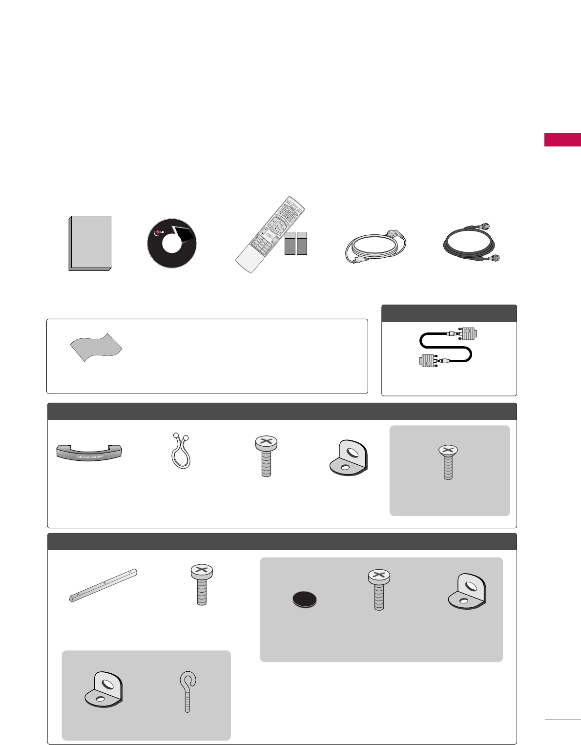
ACCESSORIES
Ensure that the following accessories are included with your product. If an accessory is missing, please contact
the dealer where you purchased the product.
User must use shielded signal interface cables (D-sub 15 pin cable) with ferrite cores to maintain standard
compliance for the product.
The accssories can be different from the figures shown here.
OOppttiioonn EExxttrraass
FFoorr LLCCDD TTVV mmooddeellss
Cable
Management
Twist Holder
Arrange the wires with the
twist holder. 4-Bolts for stand assembly
(Refer to p.12)
For 37LB5D
FFoorr PPllaassmmaa TTVV mmooddeellss ((RReeffeerr ttoo pp..1133))
Additional Cover
(Refer to p.13)
3- Bolts
(Refer to p.13)
* Slightly wipe stained spot on the exterior only with the polishing cloth
for the product exterior if there is stain or fingerprint on surface of the
exterior.
* Do not wipe roughly when removing stain. Please be cautions of that
excessive pressure may cause scratch or discoloration.
Polishing Cloth
LCD TV PLASMA TV
Owner's Manual
http://www.lgusa.com
www.lg.ca
Copyright© 2007 LGE,
All Rights Reserved.
D-sub 15 pin Cable
1.5V 1.5V
Owner’s Manual Power Cord 75ohm Round Cable
Remote Control,
Batteries
1 2 3
456
78
0
9
BACK
VOLCH
MUTE
FAV
BRIGHT -
MENU
BRIGHT +
ENTER
EXIT
TIMER
RATIO
SIMPLINK
POWER
VCR
TV
DVD
AUDIO
CABLE
STB
MODE
TV INPUT
INPUT
CH
FAV
MENU
BRIGHT +
ENTER
T
TIMER
RATIO
SIMPLINK
1
VOL
MUTE
EXIT
CD Manual
2- TV Bracket
Bolts
(Refer to p.16)
2- TV Brackets,
2- Wall Brackets
(Refer to p.16)
2- Rubbers
(Refer to p.13)
For 60PY3D
2- TV Bracket
Bolts
(Refer to p.16)
2- TV Brackets,
2- Wall Brackets
(Refer to p.16)
2- Wall Brackets
(Refer to p.16)
2- Eye Bolts
(Refer to p.16)
For 50PY3D
PREPARATION
8
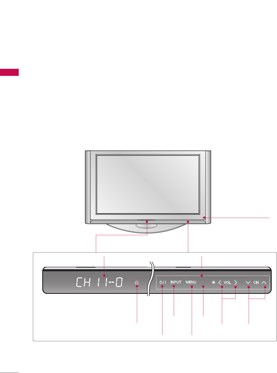
FRONT PANEL INFORMATION
PREPARATION
■
Here shown may be somewhat different from your TV.
■
NOTE: If your product has a protection tape attached, remove the tape.
And then wipe the product with a cloth (If a polishing cloth is included with your product, use it).
Plasma TV Model
50/60PY3D
Remote Control Sensor
ENTER
ENTER
..
ENTER
VOLUME
(FF,GG)
Buttons
CHANNEL
(EE,DD)
Buttons
ENTER
Button
INPUT
Button
MENU
Button
POWER
Button
Power/Standby Indicator
Illuminates red in standby mode.
Illuminates white when the set is switched on.
Program Display Touch Pad
PREPARATION
9
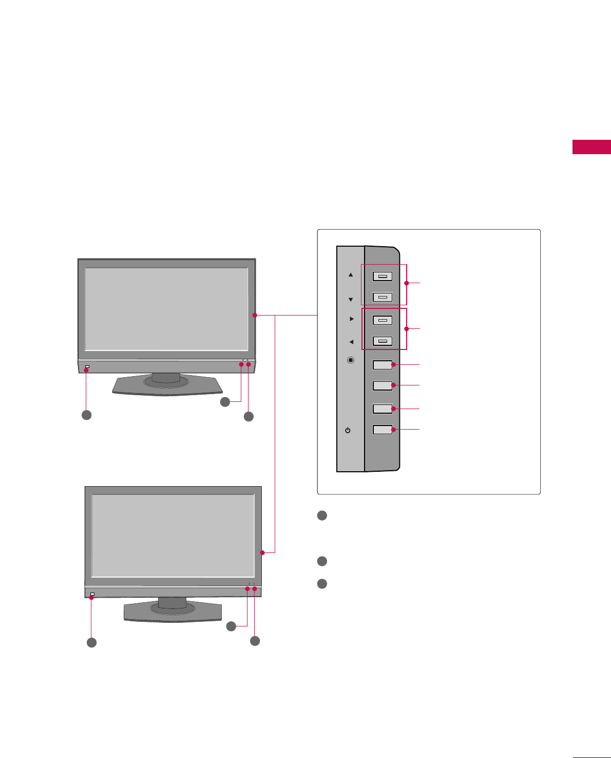
CH
VOL
ENTER
MENU
INPUT
/I
CHANNEL (DD,EE)Buttons
VOLUME (FF,GG)Buttons
ENTER Button
MENU Button
INPUT Button
POWER Button
LCD TV Model
2
3
1
2
3
1
Intelligent Eye
Adjusts picture according to the surrounding
conditions.
Remote Control Sensor
Power/Standby Indicator
Illuminates red in standby mode.
Illuminates green when the set is switched on.
1
2
3
37/42/47/52LB5D
47LC7DF
PREPARATION
10
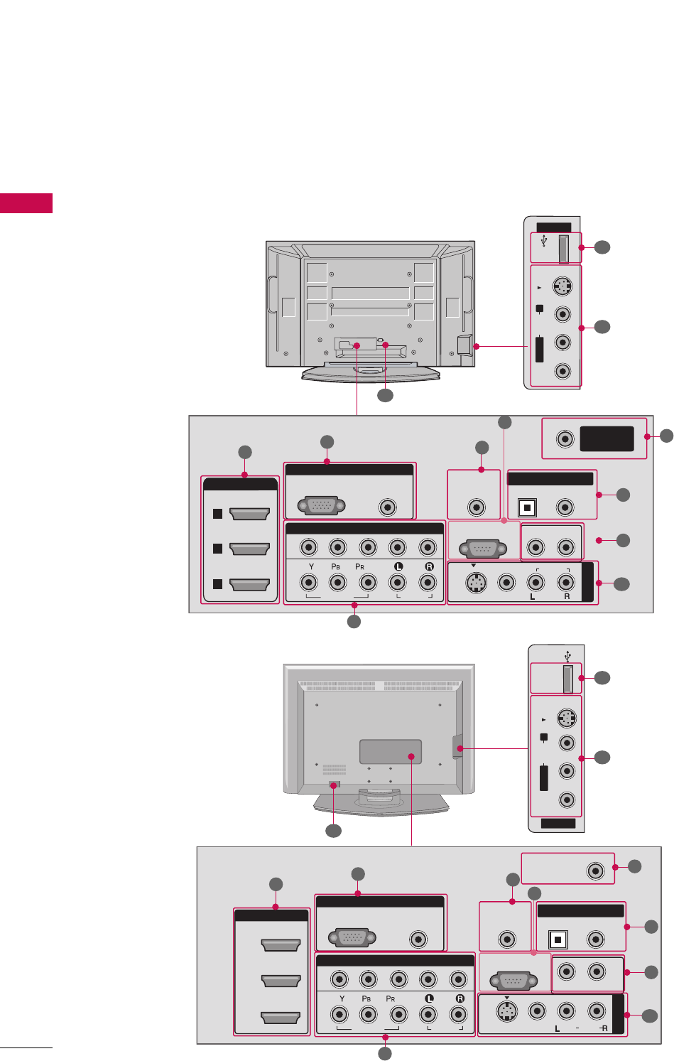
BACK PANEL INFORMATION
PREPARATION
Plasma TV Model
LCD TV Model
( )
AV IN 2
L/MONO
R
AUDIO
VIDEO
S-VIDEO
USB
RGB IN
COMPONENT IN
AUDIO
(RGB/DVI)
RGB(PC)
REMOTE
CONTROL IN
ANTENNA/
CABLE IN
1
2
RS-232C IN
(CONTROL & SERVICE)
VIDEO
AUDIO
VIDEO
AUDIO OUT
OPTICAL COAXIAL
MONO
( )
AUDIO
S-VIDEO
DIGITAL AUDIO OUT
AV IN 1
R
HDMI/DVI IN
3
2
1
■
Here shown may be somewhat different from your TV.
134
5
6
7
8
2
11
10
9
9
( )
AV IN 2
L/MONO
R
AUDIO
VIDEO
S-VIDEO
USB IN
RGB IN
HDMI/DVI IN
COMPONENT IN
AUDIO
(RGB/DVI)
RGB(PC)
REMOTE
CONTROL IN
ANTENNA/
CABLE IN
11
2
2
3
RS-232C IN
(CONTROL & SERVICE)
VIDEO
AUDIO
VIDEO
AUDIO OUT
OPTICAL COAXIAL
MONO
( )
AUDIO
S-VIDEO
DIGITAL AUDIO OUT
AV IN 1
R
134
5
6
7
8
2
11
10
9
9

PREPARATION
11
HDMI/DVI IN
Connect a HDMI signal to 1, 2 or 3.
Or DVI (VIDEO) signal to the 1, 2 or 3 port with a
DVI to HDMI cable.
COMPONENT IN
Connect a component video/audio device to these
jacks.
RGB (PC)
AUDIO (RGB/DVI)
Connect the monitor output from a PC to the
appropriate input port.
REMOTE CONTROL PORT
Connect your wired remote control.
RS-232C IN (CONTROL & SERVICE) PORT
Connect to the RS-232C port on a PC.
ANTENNA/CABLE IN
Connect over-the air signals to this jack.
Connect cable signals to this jack.
DIGITAL AUDIO OUT
Connect digital audio to various types of equipment.
Note: In standby mode, these ports do not work.
AUDIO OUT
Connect analog audio to various types of equipment.
AV (Audio/Video) IN 1/2
Connect audio/video output from an external
device to these jacks.
S-VIDEO
Connect S-Video out from an S-VIDEO device.
USB INPUT
Power Cord Socket
For operation with AC power.
Caution: Never attempt to operate the TV on DC
power.
1
2
3
4
5
6
7
8
9
10
11
PREPARATION
12
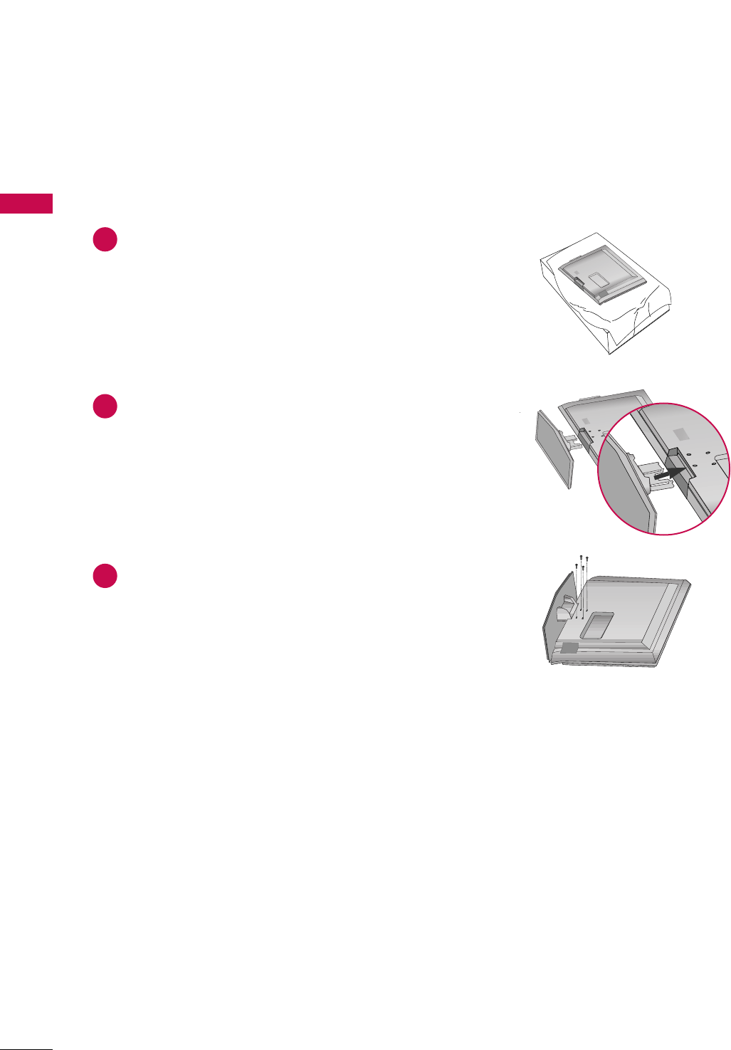
STAND INSTALLATION (Only 37LB5D)
PREPARATION
Carefully place the product screen side down on
a cushioned surface that will protect product and
screen from damage.
Assemble the product stand with the product as
shown.
Securely install the 4 bolts provided.
1
2
3
PREPARATION
13
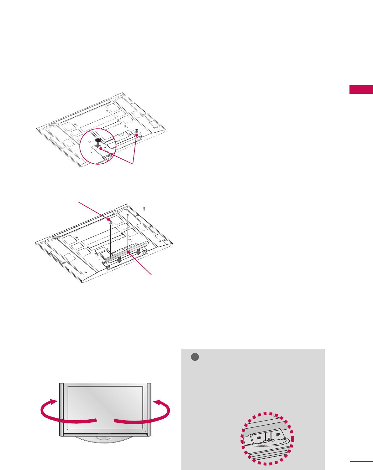
NOT USING THE DESK-TYPE STAND (For Plasma TV)
When not using the desk-type stand, install the sup-
plied desk-type stand fixture protection rubber caps
as shown at the figure.
To prevent the foreign materials from entering the
desk-type stand fixture, fix the desk-type stand fixture
protection cover(additional cover) by using the sup-
plied bolts as shown at the figure.
ADDITIONAL COVER
BOLT
RUBBER
■
It is applied to when installing only the 60PY3D model as wall-type.
■
It is applied to when installing only the 50/60PY3D model as wall-type.
After installing the TV, you can adjust the the TV set manually to the left or right direction by 20 degrees to
suit your viewing position.
NOTE
!
GG Before adjusting the angle, you must remove
the cable management and loosen (to the
left) the shaft bolt on the middle of stand’s
back. And when stand be level with TV, you
must close (to the right) the shaft bolt to
set the hole.
SWIVEL STAND (For Plasma TV)
PREPARATION
14
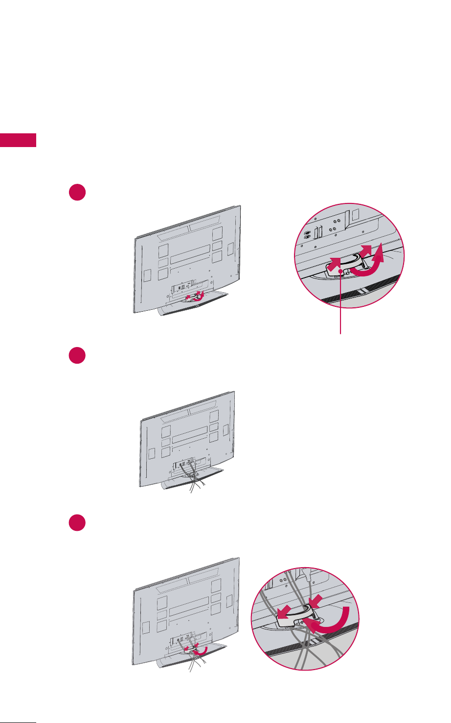
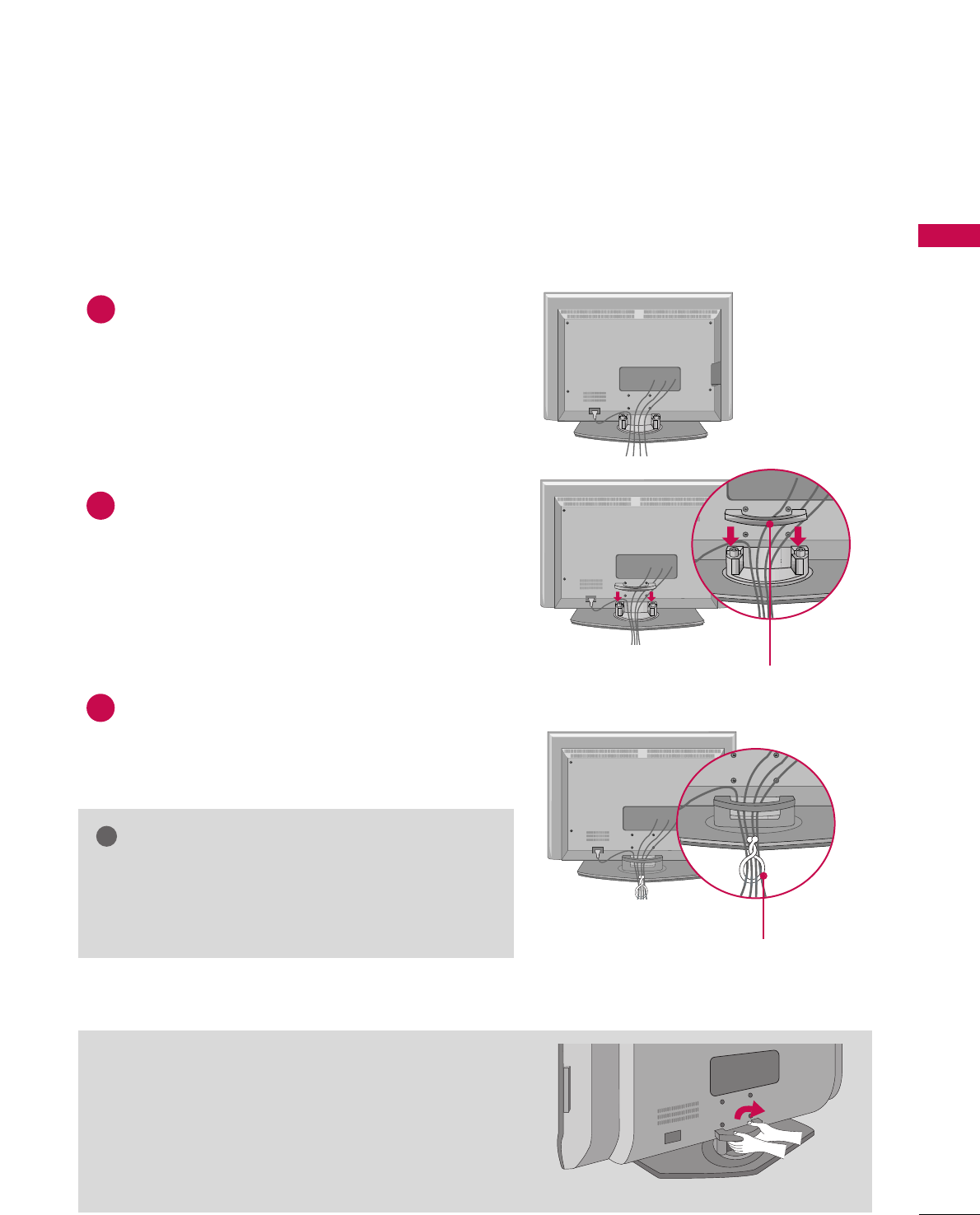
BACK COVER FOR WIRE ARRANGEMENT
PREPARATION
Plasma TV Model
Hold the CABLE MANAGEMENT with both hands and pull it backward as shown.
Connect the cables as necessary.
To connect an additional equipment, see the EXTERNAL EQUIPMENT SETUP section.
1
2
Install the CABLE MANAGEMENT as shown.
3
■
Here shown may be somewhat different from your TV.
CABLE MANAGEMENT
45
°
PREPARATION
15
LCD TV Model
Connect the cables as necessary.
To connect an additional equipment, see the
EXTERNAL EQUIPMENT SETUP section.
Install the CABLE MANAGEMENT as shown.
How to remove the CABLE MANAGEMENT
GGHold the CABLE MANAGEMENT with both hands and
pull it backward.
CABLE MANAGEMENT
GGDo not hold the CABLE MANAGEMENT when moving
the product.
- If the product is dropped, you may be injured or the
product may be broken.
NOTE
!
1
2
Bundle the cables using the supplied TWISTER
HOLDER.
TWISTER HOLDER
3
PREPARATION
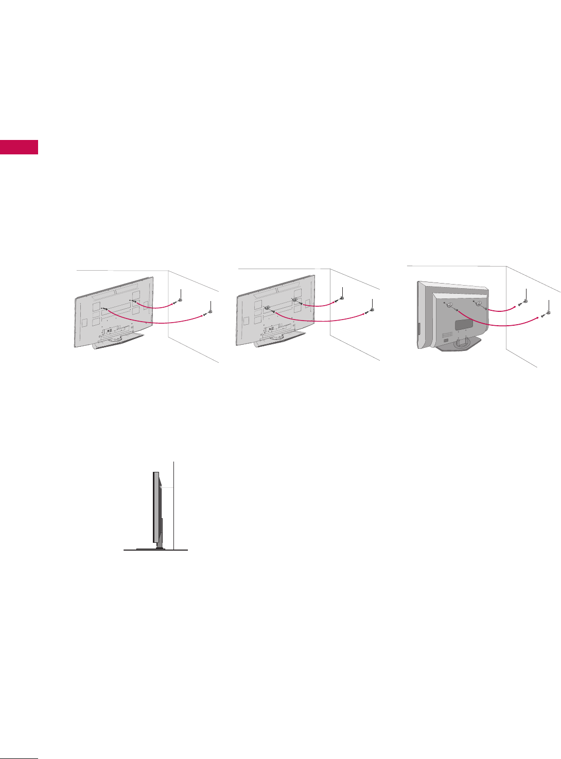
16
ATTACHING THE TV TO A WALL
PREPARATION
We recommend that you set up the TV close to a wall so it cannot fall over if pushed backwards.
Additionally, we recommend that the TV be attached to a wall so it cannot be pulled in a forward direction,
potentially causing injury or damaging the product.
Caution: Please make sure that children don’t climb on or hang from the TV.
Plasma TV Model LCD TV Model
■Insert the eye-bolts (or TV brackets and bolts) to tighten the product to the wall as shown in the picture.
*If your product has the bolts in the eye-bolts position before inserting the eye-bolts, loosen the bolts.
Secure the wall brackets with the bolts (not provided as parts of the product, must purchase separately) to
the wall. Match the height of the bracket that is mounted on the wall to the holes in the product.
Ensure the eye-bolts or brackets are tightened securely.
■Use a sturdy rope (not provided as parts of the product, must pur-
chase separately) to tie the product. It is safer to tie the rope so it
becomes horizontal between the wall and the product.
■
Here shown may be somewhat different from your TV.
50PY3D 60PY3D
PREPARATION
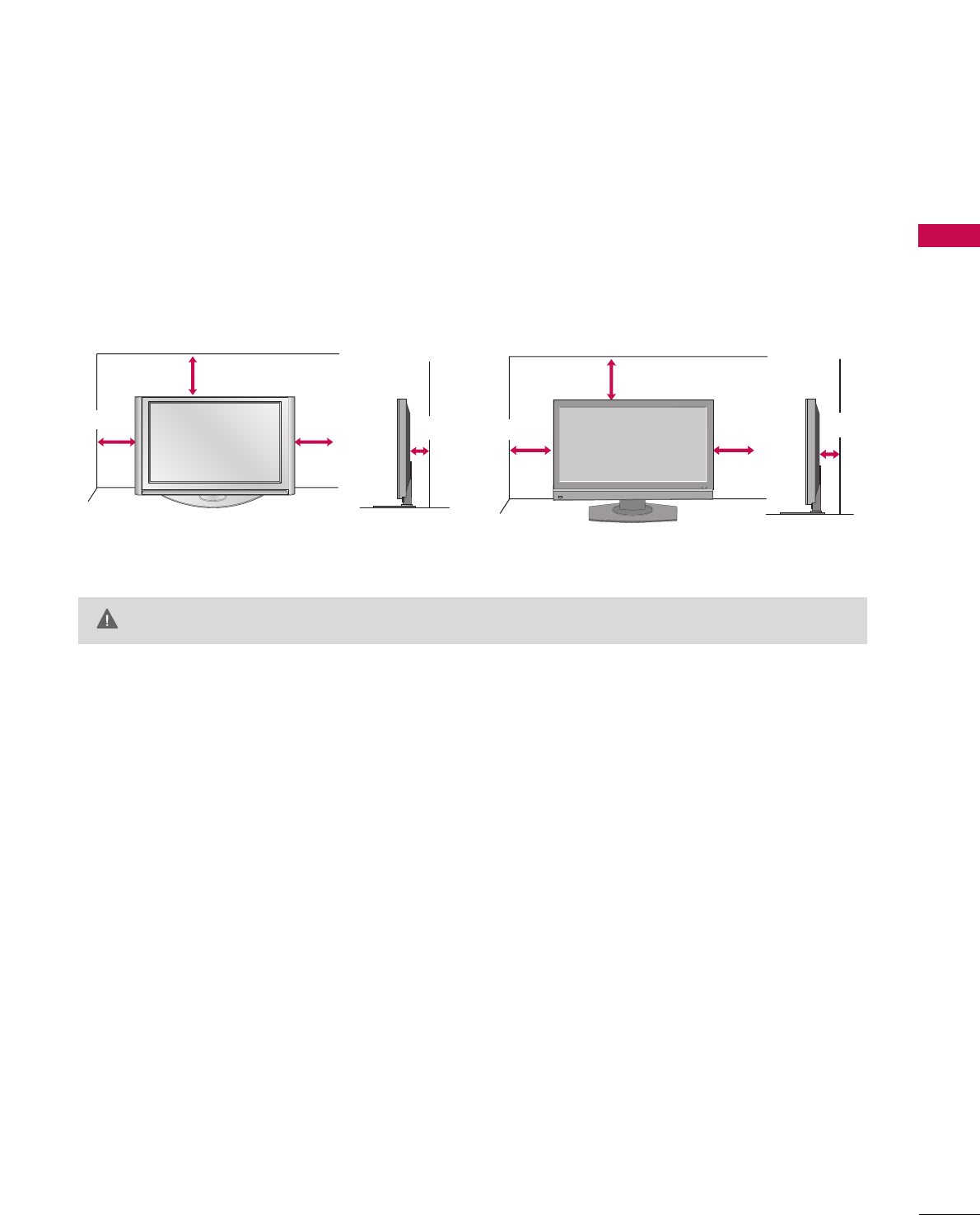
17
DESKTOP PEDESTAL INSTALLATION
For proper ventilation, allow a clearance of 4inches on all four sides from the wall.
GGEnsure adequate ventilation by following the clearance recommendations.
CAUTION
Plasma TV Model LCD TV Model
4 inches
4 inches
4 inches 4 inches
4 inches
4 inches
4 inches 4 inches
PREPARATION
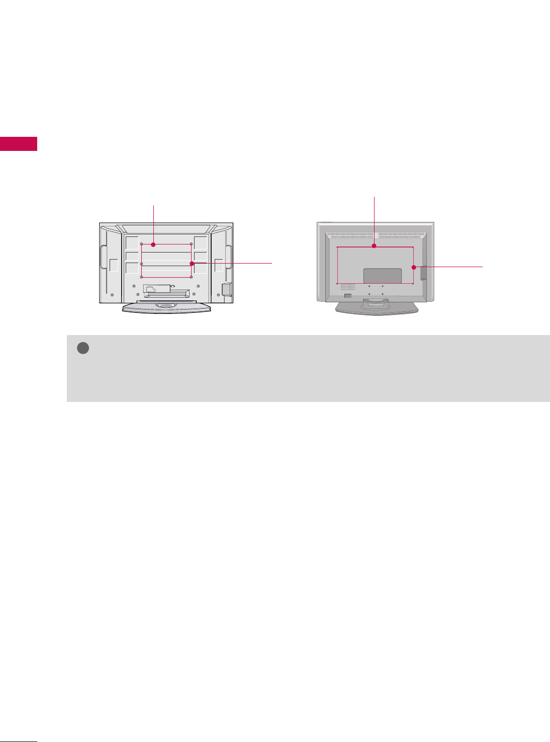
18
VESA WALL MOUNTING
PREPARATION
This product accepts a VESA-compliant mounting interface pad. (optional)
There 4 threaded holes are available for attaching the bracket.
GGScrew length needed depends on the wall mount used. For further information, refer to the VESA
Wall Mounting Instruction Guide.
NOTE
!
Plasma TV Model LCD TV Model
AV IN 2
L/ MONO
R
AUDIO
VIDEO
S-VIDEO
USB
600 mm
400 mm 400 mm
600 mm
(47/52 inches only: 800 mm)
PREPARATION
19
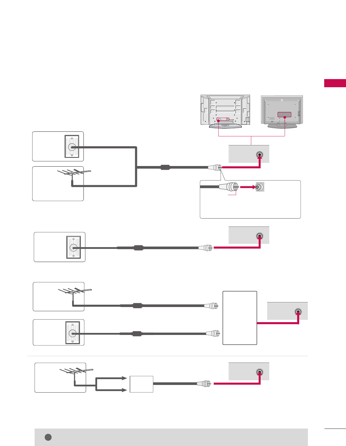
ANTENNA OR CABLE CONNECTION
1. Antenna (Analog or Digital)
Wall Antenna Socket or Outdoor Antenna without a Cable Box
Connections.
For optimum picture quality, adjust antenna direction if needed.
2. Cable
Wall
Antenna
Socket
Outdoor
Antenna
(VHF, UHF)
Cable TV
Wall Jack
Multi-family Dwellings/Apartments
(Connect to wall antenna socket)
RF Coaxial Wire (75 ohm)
RF Coaxial Wire (75 ohm)
Single-family Dwellings /Houses
(Connect to wall jack for outdoor antenna)
Be careful not to bend the bronze wire
when connecting the antenna.
Copper Wire
GGThe TV will let you know when the analog, cable, and digital channel scans are complete.
NOTE
!
■To improve the picture quality in a poor signal area, please purchase a signal amplifier and install properly.
■If the antenna needs to be split for two TV’s, install a 2-Way Signal Splitter.
■If the antenna is not installed properly, contact your dealer for assistance.
Antenna
UHF
Signal
Amplifier
VHF
3. Using both cable and antenna
Cable TV
Wall Jack
Antenna
RF Coaxial Wire (75 ohm)
RF Coaxial Wire (75 ohm)
AV IN 2
L/ MONO
R
AUDIO
VIDEO
S-VIDEO
USB
ANTENNA/
CABLE IN
( )
R
ANTENNA/
CABLE IN
( )
R
ANTENNA/
CABLE IN
( )
R
ANTENNA/
CABLE IN
( )
R
Diplexer
(Signal
Combiner)
■
Here shown may be somewhat different from your TV.
EXTERNAL EQUIPMENT SETUP
20
EXTERNAL EQUIPMENT SETUP
HD RECEIVER SETUP
This TV can receive Digital Over-the-air/Cable signals without an external digital set-top box. However, if you
do receive digital signals from a digital set-top box or other digital external device, refer to the figure as shown
below.
This TV supports HDCP (High-bandwidth Digital Contents Protection)protocol for Digital Contents.
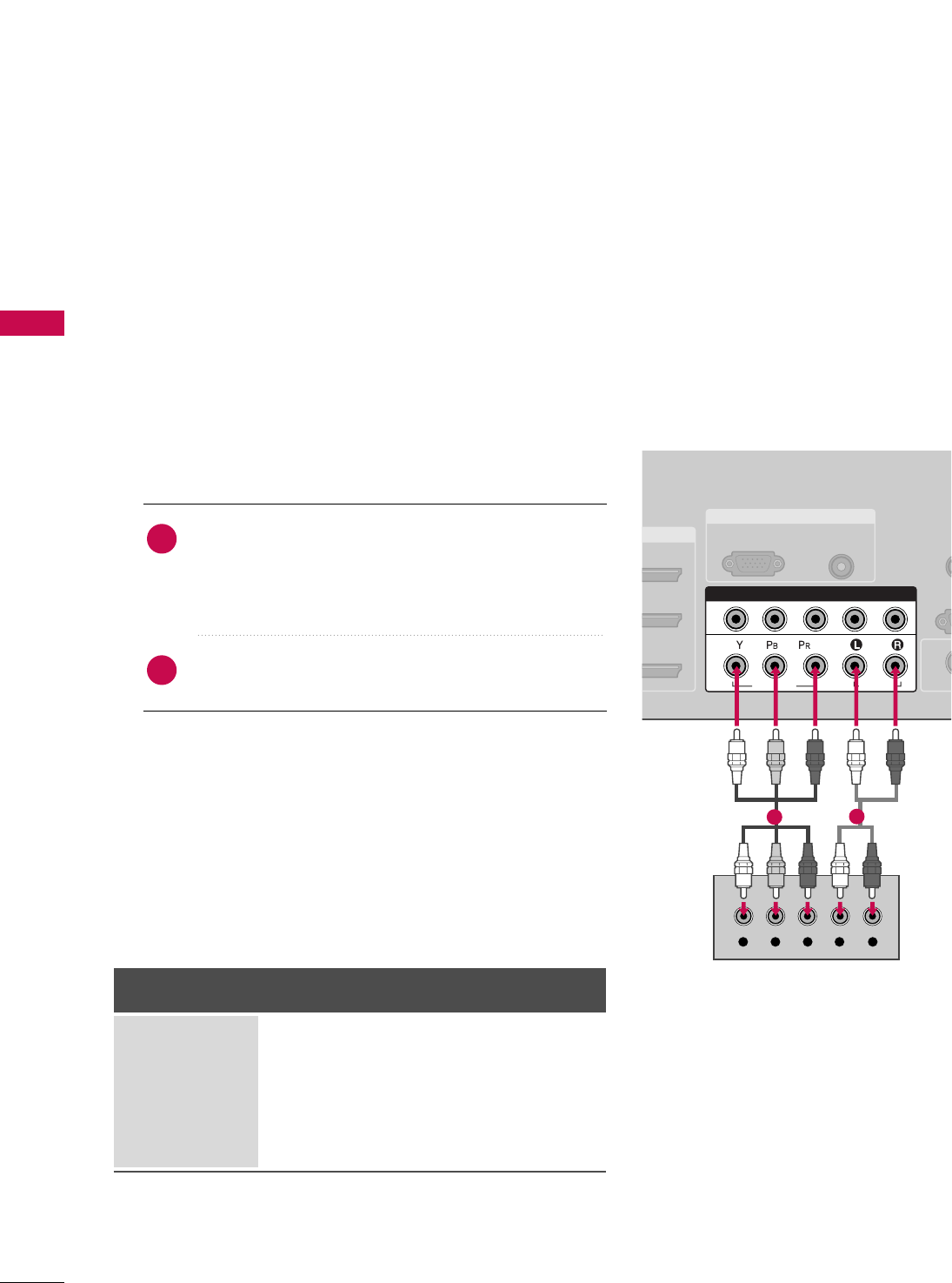
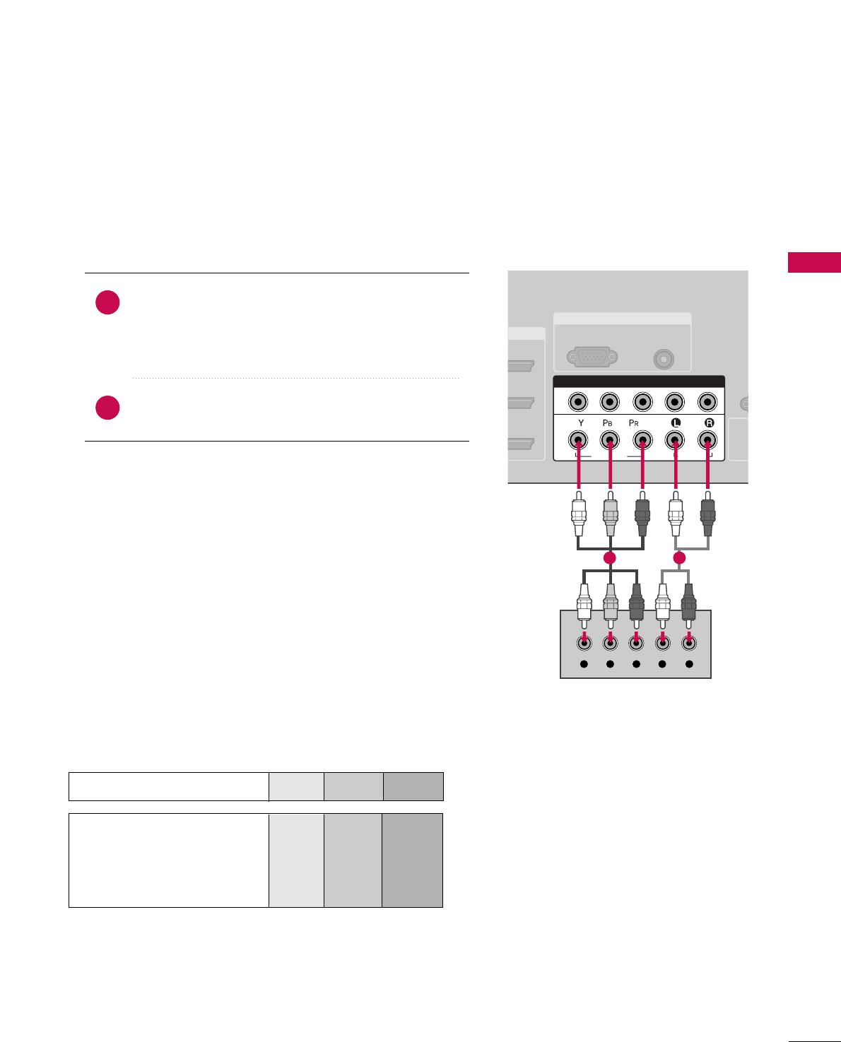
When connecting Component cable
1. How to connect
Connect the video outputs (Y, PB, PR)of the digital set
top box to the CCOOMMPPOONNEENNTT IINN VVIIDDEEOO 11jacks on
the set. Match the jack colors
(Y = green, PB= blue, and PR= red).
Connect the audio output of the digital set-top box to
the CCOOMMPPOONNEENNTT IINN AAUUDDIIOO 11jacks on the set.
2
1
2. How to use
■Turn on the digital set-top box.
(Refer to the owner’s manual for the digital set-top box. operation)
■Select CCOOMMPPOONNEENNTT 11input source by using the
IINNPPUUTTbutton on the remote control.
■If connected to CCOOMMPPOONNEENNTT IINN22input, select
CCoommppoonneenntt 22input source.
Signal
480i
480p
720p
108 0 i
108 0 p
Component 1/2
Yes
Yes
Yes
Yes
Yes
HDMI/DVI1, 2 or 3
No
Yes
Yes
Yes
Yes
■To prevent the equipment damage, never plug in any power cords until you have finished connecting all equipment.
■This part of EXTERNAL EQUIPMENT SETUP mainly use picture for LCD TV model.
RGB IN
I/DVI IN
AUDIO
(RGB/DVI)
RGB(PC)
RE
CONT
RS
(CONTR
( )
S-V
( )
( )
COMPONENT IN
1
2
VIDEO
AUDIO
Y L RPBPR
( )
12
EXTERNAL EQUIPMENT SETUP
21
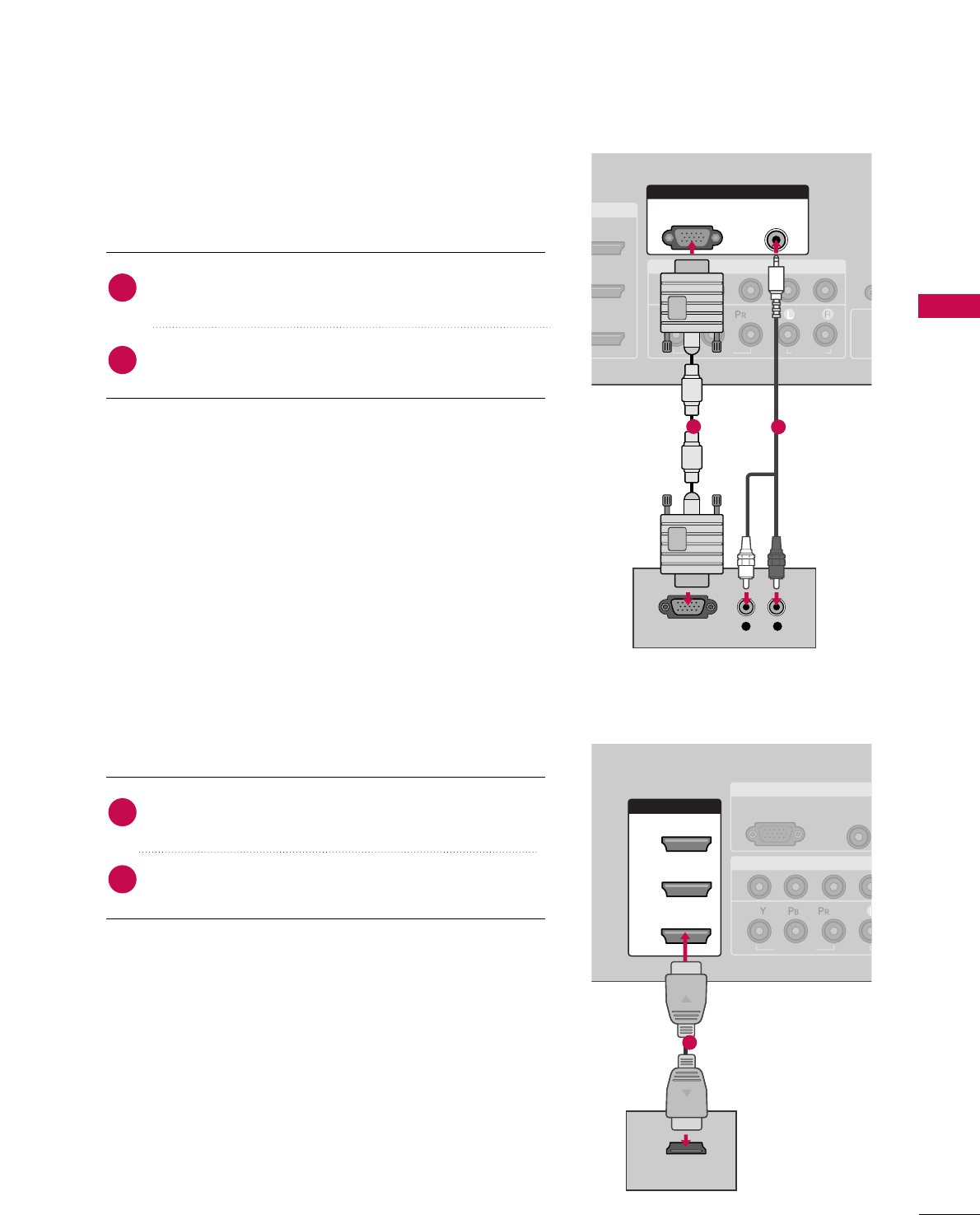
When connecting D-sub 15pin cable
( )
/DVI IN
COMPONENT IN
R
CO
1
2
R
(CON
VIDEO
AUDIO
( )
S
( )
RGB IN
AUDIO
(RGB/DVI)
RGB(PC)
L R
RGB OUTPUT
( )
( )
( )
RGB IN
COMPONENT IN
AUDIO
(RGB/DV
RGB(PC)
1
2
VIDEO
( )
HDMI/DVI IN
1
2
3
HDMI-DTV OUTPUT
( )
Connect the RGB output of the digital set-top box to
the RRGGBB ((PPCC))jack on the set.
Connect the audio outputs of the set-top box to the
AAUUDDIIOO ((RRGGBB//DDVVII))jack on the set.
1. How to connect
2. How to use
■Turn on the PC and the set.
■Select RRGGBB--PPCCinput source with using the IINNPPUUTTbutton
on the remote control.
When connecting HDMI cable
Connect the digital set-top box to HHDDMMII//DDVVII IINN11,
22 or 33 jack on the set.
No separated audio connection is necessary.
HDMI supports both audio and video.
1. How to connect
2. How to use
■Turn on the digital set-top box.
(Refer to the owner’s manual for the digital set-top box.)
■Select HHDDMMII11,HHDDMMII22 or HHDDMMII33input source with using
the IINNPPUUTTbutton on the remote control.
■If the digital set-top box player does not support Auto HDMI,
you need to set the output resolution appropriately.
2
1
2
1
12
1
EXTERNAL EQUIPMENT SETUP
22
EXTERNAL EQUIPMENT SETUP
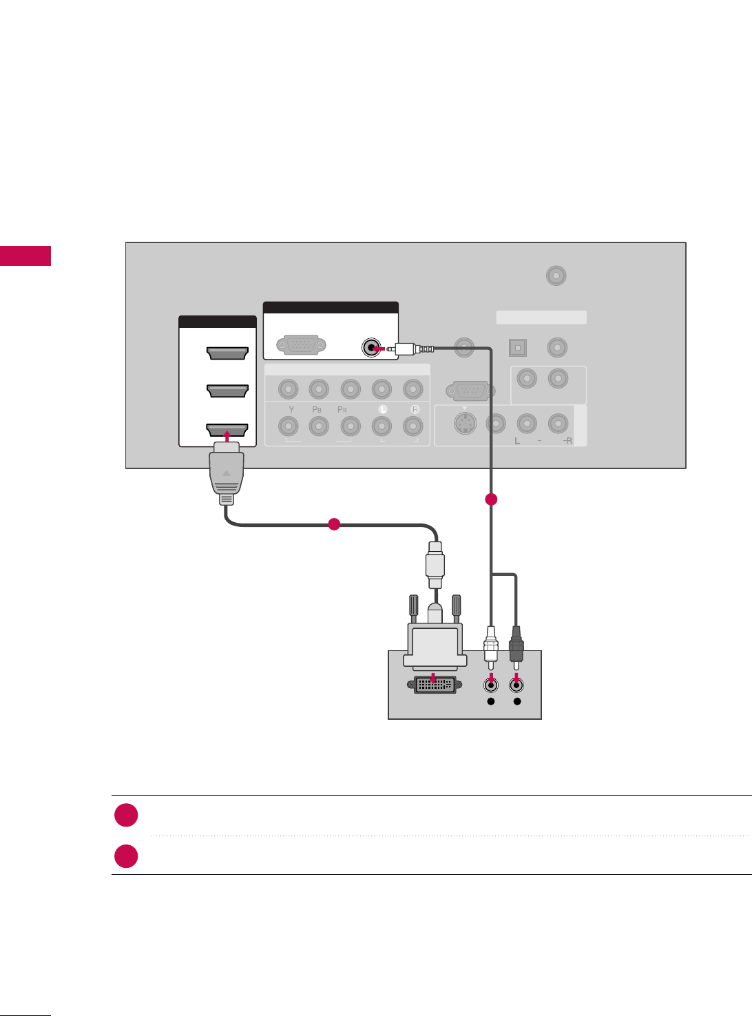
When connecting HDMI to DVI cable
( )
( )
( )
COMPONENT IN
AV IN 1
REMOTE
CONTROL IN
ANTENNA/
CABLE IN
1
2
RS-232C IN
(CONTROL & SERVICE)
VIDEO
AUDIO
AUDIO OUT
OPTICAL COAXIAL
DIGITAL AUDIO OUT
VIDEO
MONO
( )
AUDIO
S-VIDEO
HDMI/DVI IN
1
2
3
RGB IN
AUDIO
(RGB/DVI)
L R
DVI-DTV OUTPUT
RGB(PC)
Connect the DVI output of the digital set-top box to the HHDDMMII//DDVVII IINN11, 22 or 33 jack on the set.
Connect the audio output of the digital set-top box to the AAUUDDIIOO((RRGGBB//DDVVII))jack on the set.
1. How to connect
■Turn on the digital set-top box. (Refer to the owner’s manual for the digital set-top box.)
■Select HHDDMMII11,HHDDMMII22 or HHDDMMII33input source with using the IINNPPUUTTbutton on the remote control.
2. How to use
2
1
1
2
EXTERNAL EQUIPMENT SETUP
23
DVD SETUP
When connecting Component cable
Component Input ports
To get better picture quality, connect a DVD player to the component input ports as shown below.
Component ports on the TV
YP
BPR
Video output ports
on DVD player
Y
Y
Y
Y
PB
B-Y
Cb
Pb
PR
R-Y
Cr
Pr
Connect the video outputs (Y, PB, PR)of the DVD to the
CCOOMMPPOONNEENNTT IINN VVIIDDEEOO11jacks on the set.
Match the jack colors
(Y = green, PB= blue, and PR= red).
Connect the audio outputs of the DVD to the
CCOOMMPPOONNEENNTT IINN AAUUDDIIOO11jacks on the set.
1. How to connect
2. How to use
■Turn on the DVD player, insert a DVD.
■Select CCOOMMPPOONNEENNTT 11input source by using the IINNPPUUTT
button on the remote control.
■If connected to CCOOMMPPOONNEENNTT IINN 22input, select
CCoommppoonneenntt 22input source.
■Refer to the DVD player's manual for operating instructions.
2
1
RGB IN
DVI IN
AUDIO
(RGB/DVI)
RGB(PC)
R
CO
R
(CONT
( )
S-
( )
COMPONENT IN
1
2
VIDEO
AUDIO
Y L RPBPR
( )
1 2
EXTERNAL EQUIPMENT SETUP
24
EXTERNAL EQUIPMENT SETUP
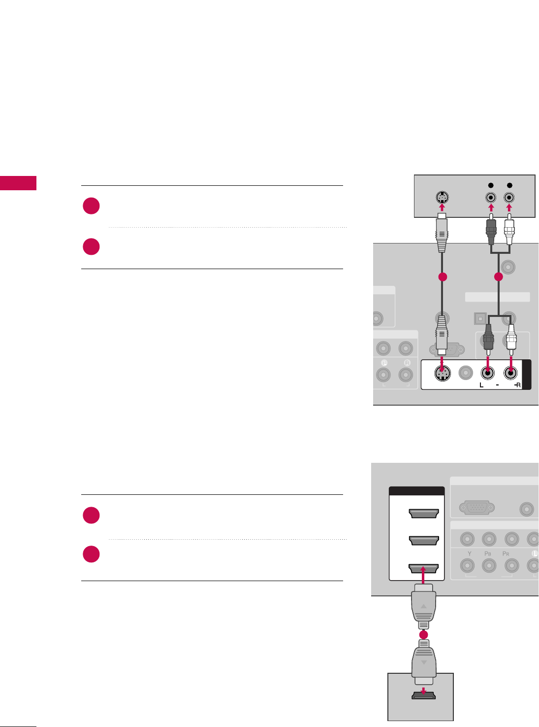
When connecting with an S-Video cable
Connect the S-VIDEO output of the DVD to the
SS--VVIIDDEEOOinput on the set.
Connect the audio outputs of the DVD to the AAUUDDIIOO
input jacks on the set.
1. How to connect
2. How to use
■Turn on the DVD player, insert a DVD.
■Select AAVV11input source by using the IINNPPUUTTbutton on the
remote control.
■If connected to AAVV IINN22, select AAVV22input source.
■Refer to the DVD player's manual for operating instructions.
When connecting HDMI cable
Connect the HDMI output of the DVD to the
HHDDMMII//DDVVII IINN 11, 22, or 33jack on the set.
No separated audio connection is necessary.
HDMI supports both audio and video.
1. How to connect
2. How to use
■Select HHDDMMII11,HHDDMMII22,orHHDDMMII33input source by using
the IINNPPUUTTbutton on the remote control.
■Refer to the DVD player's manual for operating instructions.
■If the DVD does not support Auto HDMI, you need to set
the output resolution appropriately.
2
1
2
1
( ) ( )
T IN
UDIO
B/DVI)
REMOTE
CONTROL IN
ANTENNA/
CABLE IN
RS-232C IN
(CONTROL & SERVICE)
AUDIO
AUDIO OUT
OPTICAL COAXIAL
DIGITAL AUDIO OUT
MONO
( )
AUDIO
S-VIDEO
AV IN 1
VIDEO
L R
S-VIDEO
AUDIO
12
( )
RGB IN
COMPONENT IN
AUDIO
(RGB/DVI
RGB(PC)
1
2
VIDEO
A
( )
HDMI/DVI IN
1
2
3
HDMI-DVD OUTPUT
( )
1
EXTERNAL EQUIPMENT SETUP
25
VCR SETUP
When connecting with an antenna
■To avoid picture noise (interference), leave an adequate distance between the VCR and TV.
■Use the ISM feature in the Option menu to avoid having a fixed image remain on the screen for a long period
of time
(Only
Plasma TV model
)
. If the 4:3 picture format is used; the fixed images on the sides of the
screen may remain visible on the screen. This phenomenon is common to all manufactures and in conse-
quence the manufactures warranty does not cover the product bearing this phenomenon.
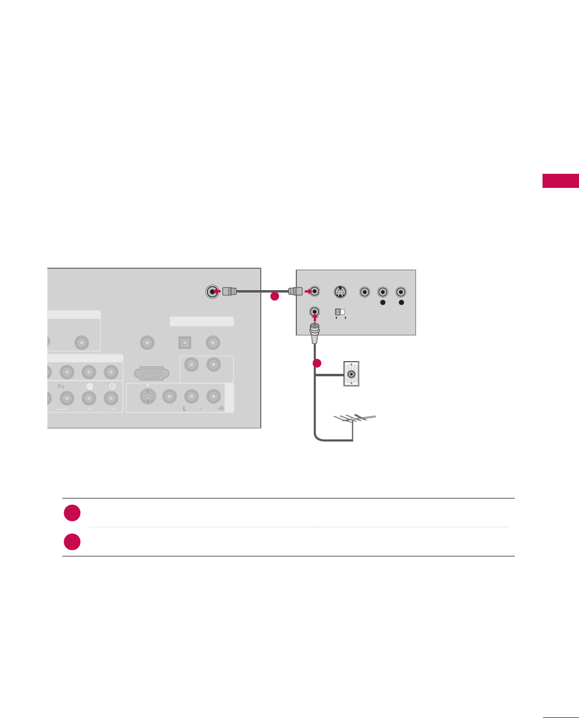
Connect the RF antenna out socket of the VCR to the AANNTTEENNNNAA//CCAABBLLEE IINNsocket on the set.
Connect the antenna cable to the RF antenna in socket of the VCR.
1. How to connect
■Set VCR output switch to 3 or 4 and then tune TV to the same channel number.
■Insert a video tape into the VCR and press PLAY on the VCR. (Refer to the VCR owner’s manual.)
2. How to use
2
1
L R
S-VIDEO VIDEO
OUTPUT
SWITCH
ANT IN
ANT OUT
GB IN
MPONENT IN
AV IN 1
AUDIO
(RGB/DVI)
REMOTE
CONTROL IN
ANTENNA/
CABLE IN
RS-232C IN
(CONTROL & SERVICE)
EO
AUDIO
AUDIO OUT
OPTICAL COAXIAL
DIGITAL AUDIO OUT
VIDEO
MONO
( )
AUDIO
S-VIDEO
( )
( )
Wall Jack
Antenna
1
2
EXTERNAL EQUIPMENT SETUP
26
EXTERNAL EQUIPMENT SETUP
GGDo not connect to both Video
and S-Video at the same time. In
the event that you connect both
Video and the S-Video cables,
only the S-Video will work.
CAUTION
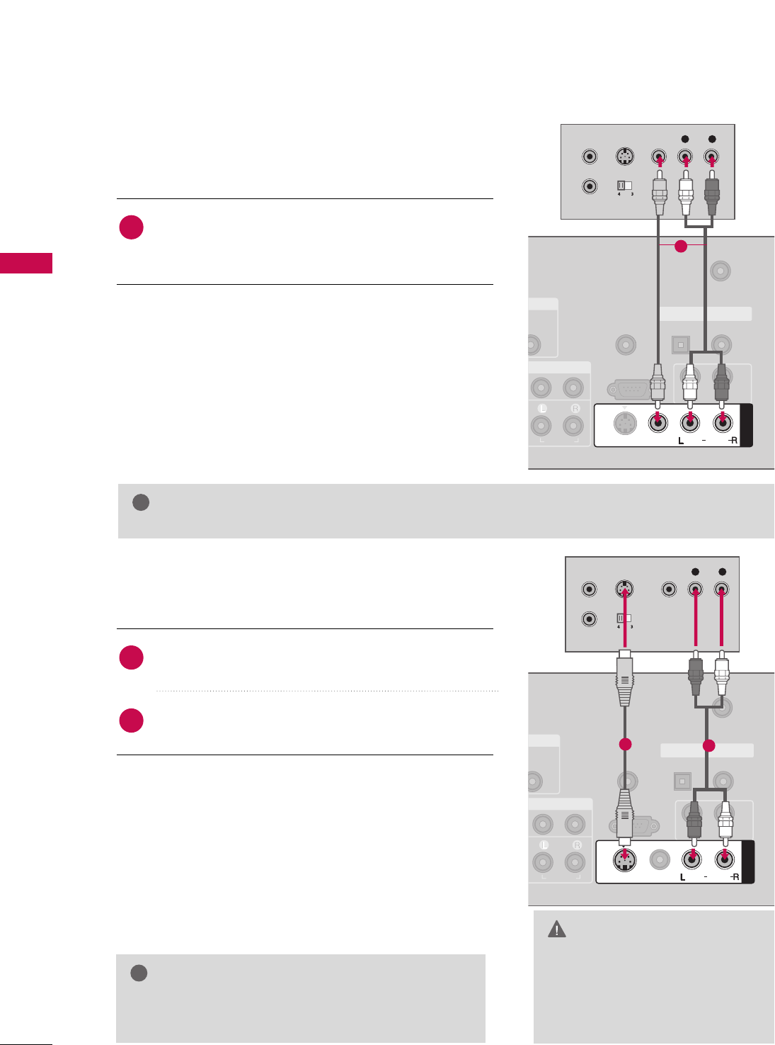
When connecting with a RCA cable
GGThe picture quality is improved: compared to normal
composite (RCA cable) input.
NOTE
!
Connect the AAUUDDIIOO/VVIIDDEEOOjacks between TV and
VCR. Match the jack colors (Video = yellow, Audio Left
= white, and Audio Right = red)
1. How to connect
2. How to use
■Insert a video tape into the VCR and press PLAY on the
VCR. (Refer to the VCR owner’s manual.)
■Select AAVV11input source by using the IINNPPUUTTbutton on
the remote control.
■If connected to AAVV IINN22, select AAVV22input source.
When connecting with an S-Video cable
Connect the S-VIDEO output of the VCR to the
SS--VVIIDDEEOO input on the set.
Connect the audio outputs of the VCR to the AAUUDDIIOO
input jacks on the set.
1. How to connect
2. How to use
■Insert a video tape into the VCR and press PLAY on the VCR.
(Refer to the VCR owner’s manual.)
■Select AAVV11input source by using the IINNPPUUTTbutton on the
remote control.
■If connected to AAVV IINN22, select AAVV22input source.
1
2
1
GGIf you have a mono VCR, connect the audio cable from the VCR to the AAUUDDIIOO
LL//MMOONNOOjack of the set.
NOTE
!
T IN
UDIO
B/DVI)
REMOTE
CONTROL IN
ANTENNA/
CABLE IN
RS-232C IN
(CONTROL & SERVICE)
AUDIO
AUDIO OUT
OPTICAL COAXIAL
DIGITAL AUDIO OUT
( )
AV IN 1
VIDEO
MONO
( )
AUDIO
L R
S-VIDEO VIDEO
OUTPUT
SWITCH
ANT IN
ANT OUT
S-VIDEO
( )
1
( )
( )
T IN
UDIO
B/DVI)
REMOTE
CONTROL IN
ANTENNA/
CABLE IN
RS-232C IN
(CONTROL & SERVICE)
AUDIO
AUDIO OUT
OPTICAL COAXIAL
DIGITAL AUDIO OUT
AV IN 1
VIDEO
MONO
( )
AUDIO
S-VIDEO
L R
S-VIDEO VIDEO
OUTPUT
SWITCH
ANT IN
ANT OUT
12
EXTERNAL EQUIPMENT SETUP
27
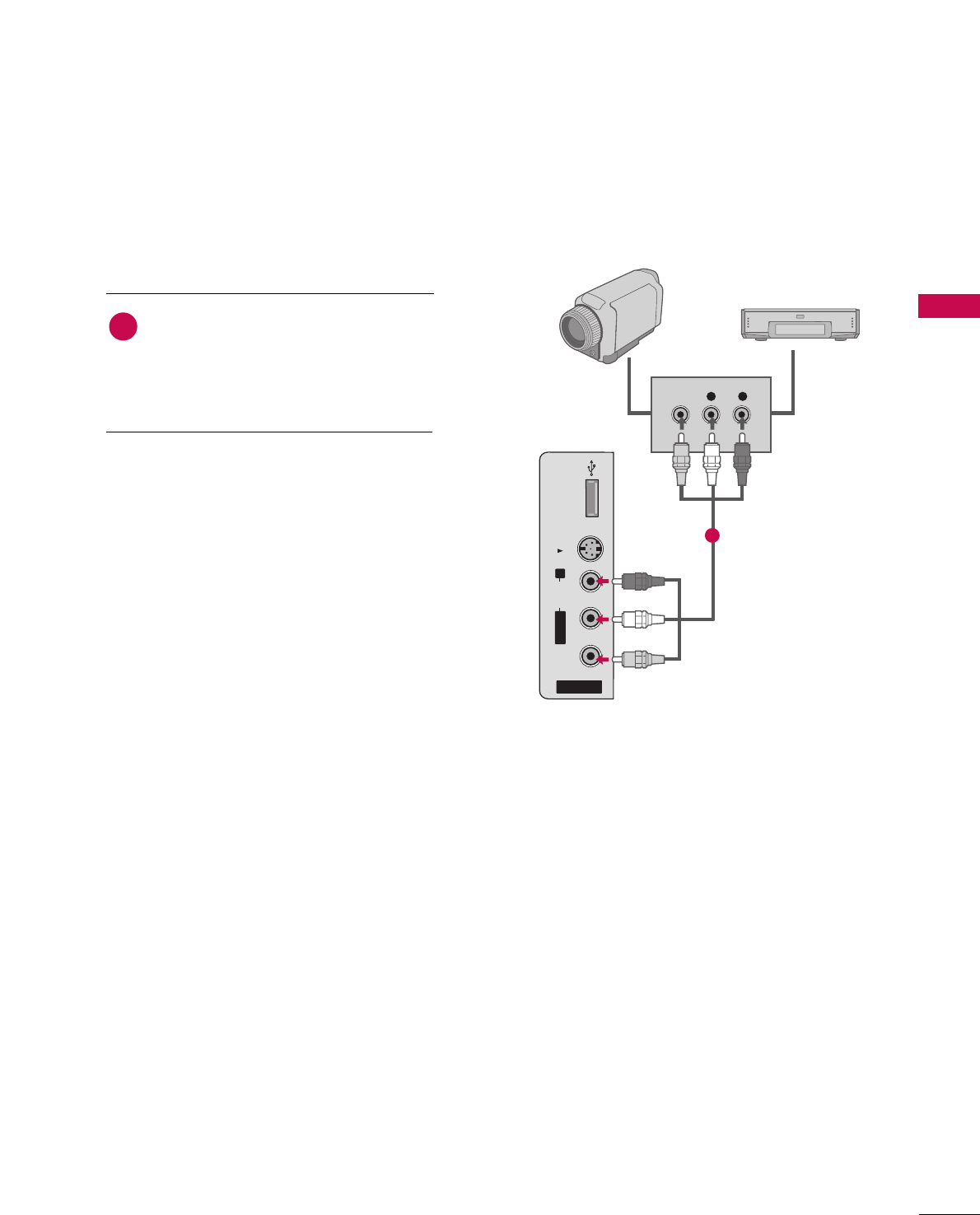
OTHER A/V SOURCE SETUP
AV IN 2
L/MONO
R
AUDIO
VIDEO
S-VIDEO
USB IN
L R
VIDEO
Camcorder
Video Game Set
Connect the AAUUDDIIOO/VVIIDDEEOOjacks
between TV and external equipment.
Match the jack colors
.
(Video = yellow, Audio Left = white, and
Audio Right = red)
1. How to connect
2. How to use
■Select AAVV22input source by using the IINNPPUUTT
button on the remote control.
■If connected to AAVV IINN11input, select AAVV11
input source.
■Operate the corresponding external equipment.
1
1
EXTERNAL EQUIPMENT SETUP
28
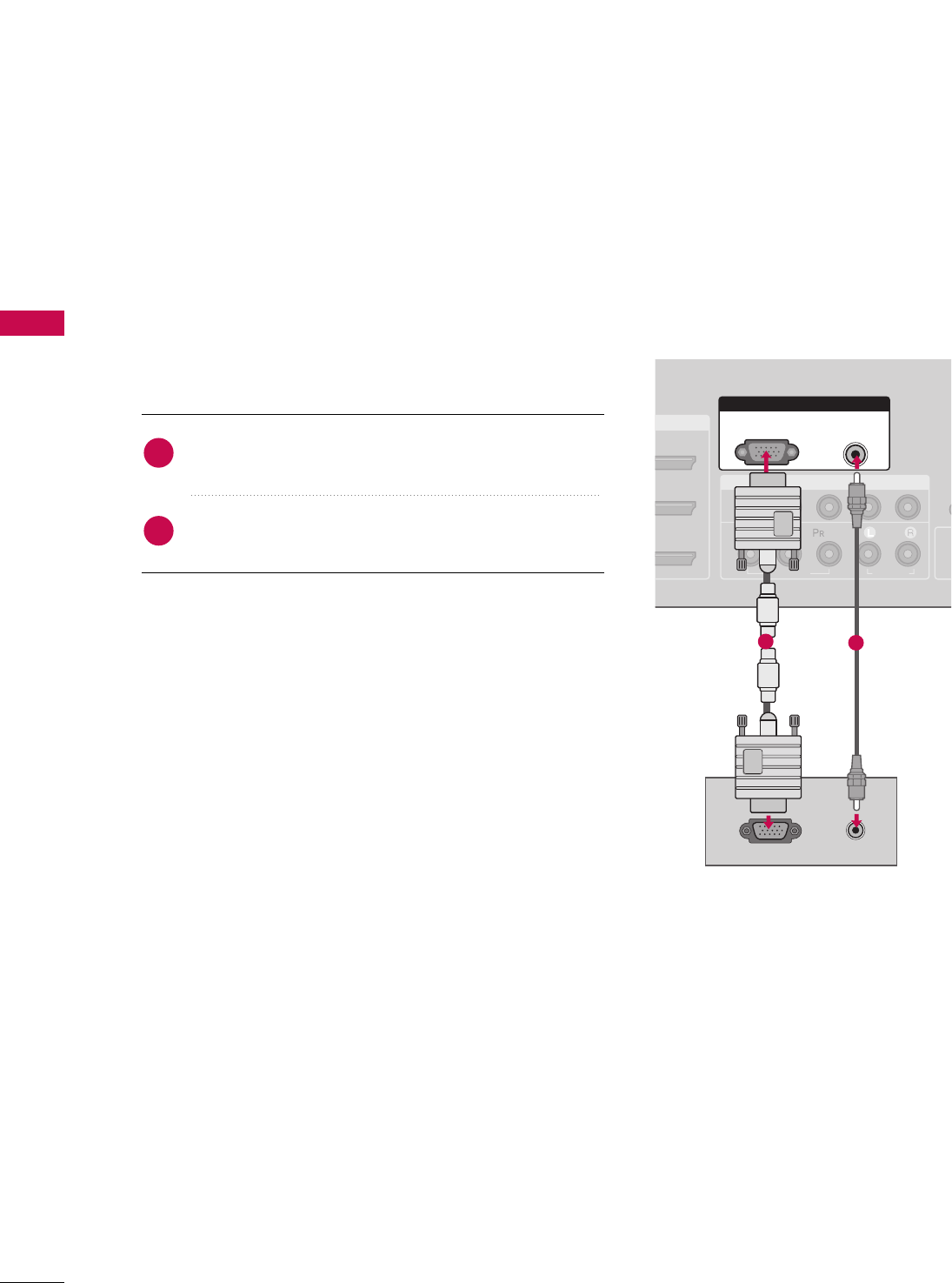
PC SETUP
EXTERNAL EQUIPMENT SETUP
This TV provides Plug and Play capability, meaning that the PC adjusts automatically to the TV's settings.
When connecting D-sub 15 pin cable
Connect the RGB output of the PC to the RRGGBB ((PPCC))
jack on the set.
Connect the PC audio output to the AAUUDDIIOO
((RRGGBB//DDVVII))jack on the set.
1. How to connect
2. How to use
■Turn on the PC and the TV.
■Select RRGGBB--PPCCinput source by using the IINNPPUUTTbutton
on the remote control.
2
1
I/DVI IN
COMPONENT IN
CO
1
2
(CO
VIDEO
AUDIO
( )
RGB IN
AUDIO
(RGB/DVI)
RGB(PC)
RGB OUTPUT AUDIO
( )
12
EXTERNAL EQUIPMENT SETUP
29
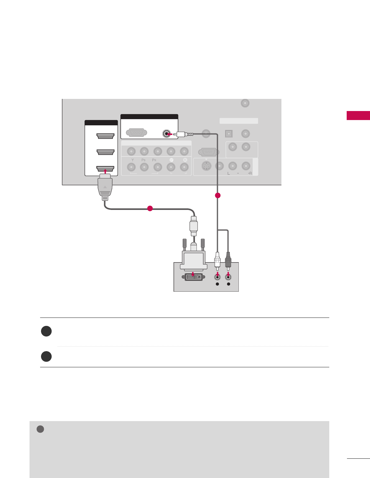
When connecting HDMI to DVI cable
Connect the DVI output of the PC to the HHDDMMII//DDVVII IINN11, 22 or 33 jack on the set.
(Use the HDMI to DVI cable)
Connect the PC audio output to the AAUUDDIIOO ((RRGGBB//DDVVII))jack on the set.
1. How to connect
2. How to use
■Turn on the PC and the TV.
■Select HHDDMMII11,HHDDMMII22 or HHDDMMII33input source by using the IINNPPUUTTbutton on the remote control.
2
1
( )
COMPONENT IN
AV IN 1
REMOTE
CONTROL IN
ANTENNA/
CABLE IN
1
2
RS-232C IN
(CONTROL & SERVICE)
VIDEO
AUDIO
AUDIO OUT
OPTICAL COAXIAL
DIGITAL AUDIO OUT
VIDEO
MONO
( )
AUDIO
S-VIDEO
HDMI/DVI IN
1
2
3
RGB IN
AUDIO
(RGB/DVI)
L R
DVI-PC OUTPUT
RGB(PC)
1
2
GGIf the PC has a DVI output and no HDMI output, a separated audio connection is necessary.
GGIf the PC does not support Auto DVI, you need to set the output resolution appropriately.
NOTE
!

EXTERNAL EQUIPMENT SETUP
30
EXTERNAL EQUIPMENT SETUP
GGTo get the the best picture quality, adjust the PC
graphics card to 1920x1080, 60Hz.
GGDepending on the graphics card, DOS mode may
not work if a HDMI to DVI Cable is in use.
GGCheck the image on your TV. There may be noise
associated with the resolution, vertical pattern,
contrast or brightness in PC mode. If noise is
present, change the PC output to another resolu-
tion, change the refresh rate to another rate or
adjust the brightness and contrast on the VIDEO
menu until the picture is clear. If the refresh rate of
the PC graphic card can not be changed, change
the PC graphic card or consult the manufacturer of
the PC graphic card.
GGAvoid keeping a fixed image on the screen for a
long period of time. The fixed image may become
permanently imprinted on the screen.
GGThe synchronization input form for Horizontal and
Vertical frequencies is separate.
NOTES
!