LG Electronics USA 50PX4DUB PDP Display User Manual 528Een

LG Electronics USA PDP Display 528Een

Contents

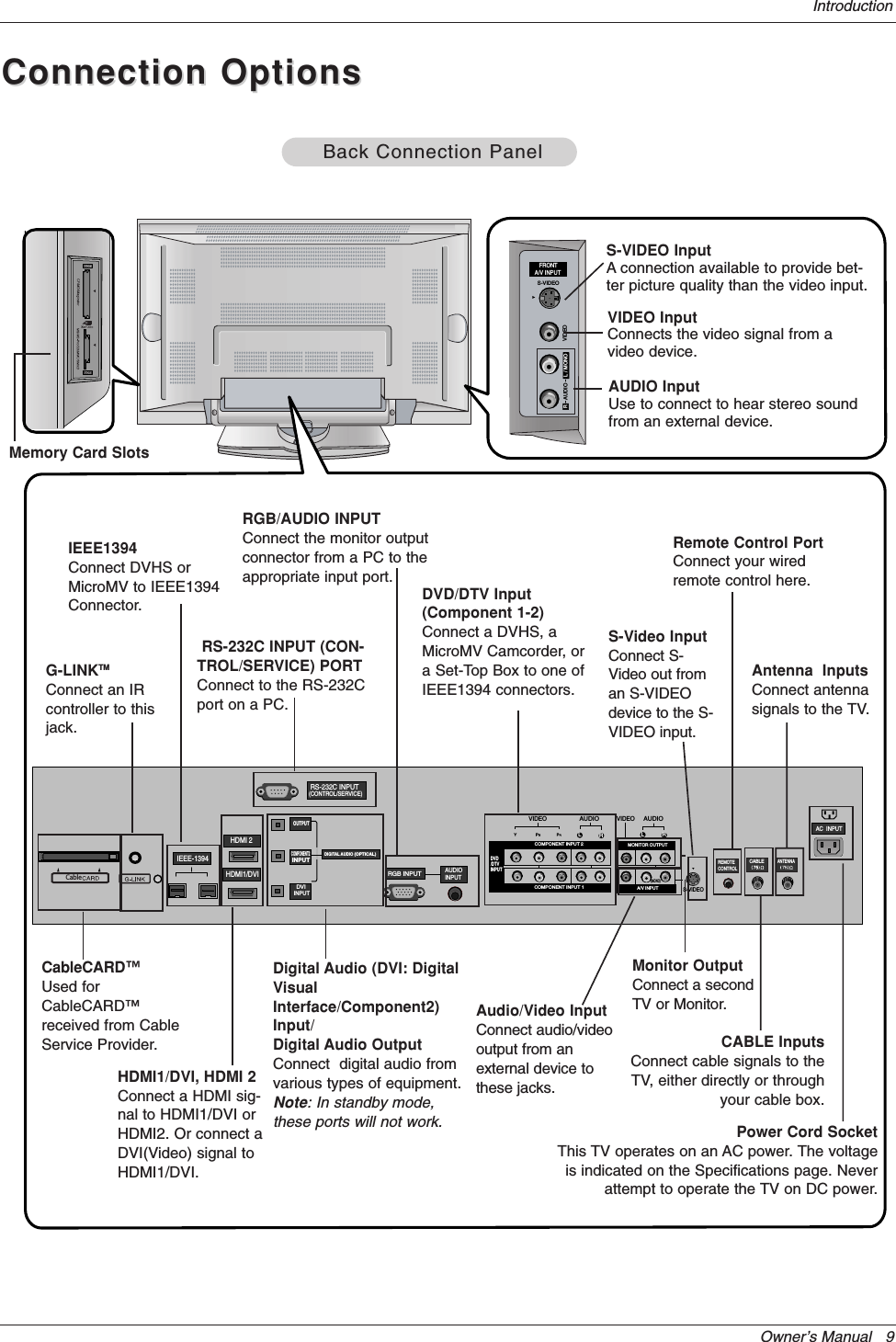
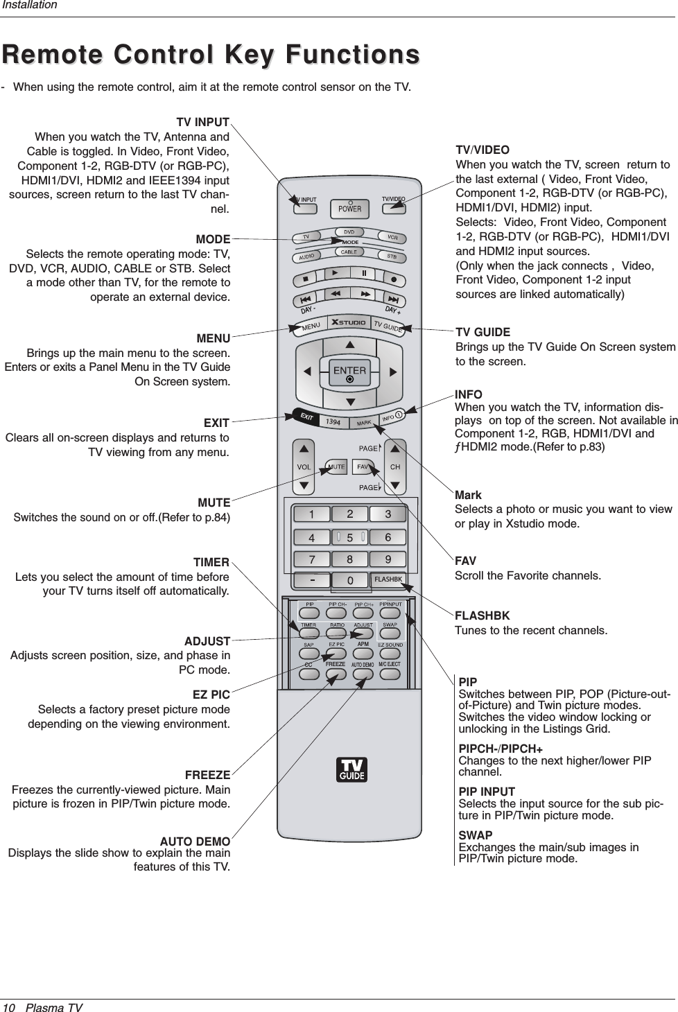
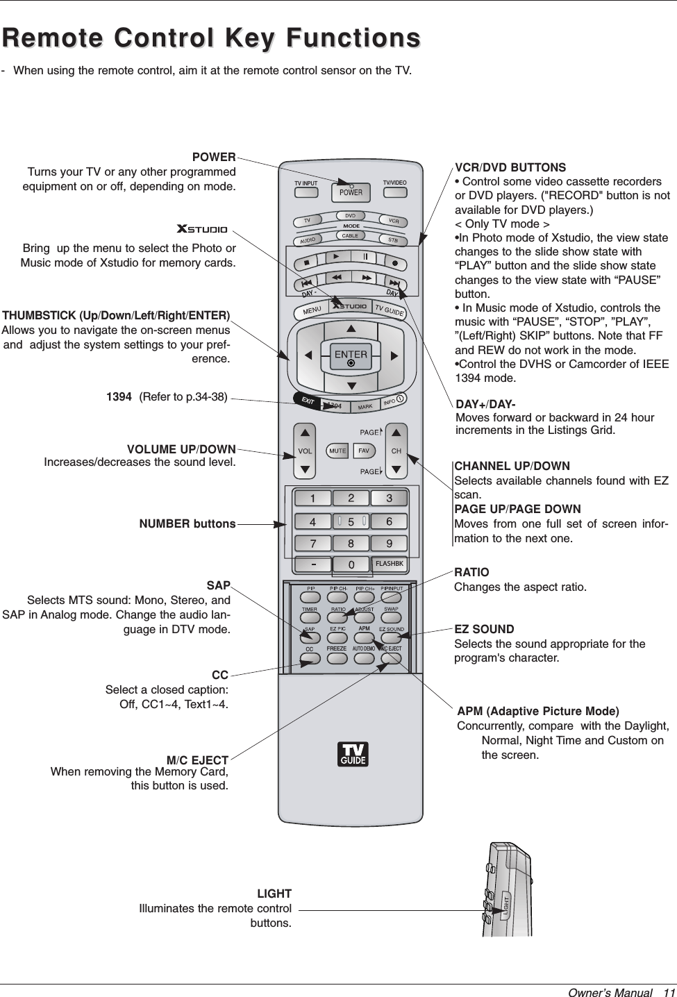
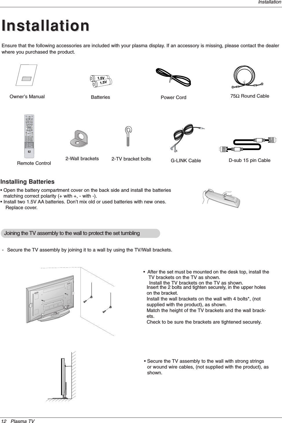
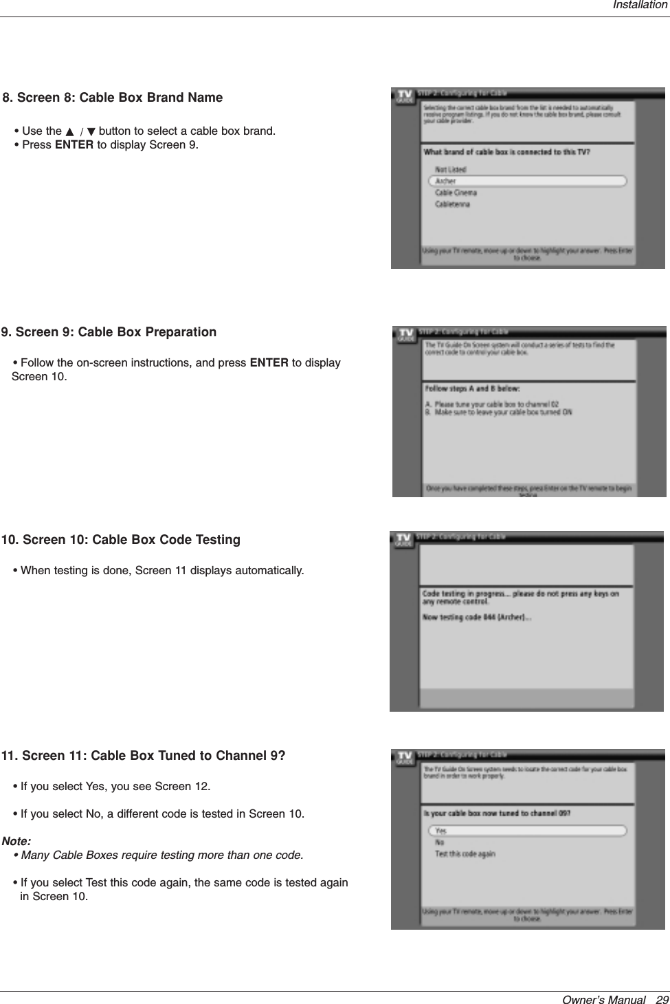
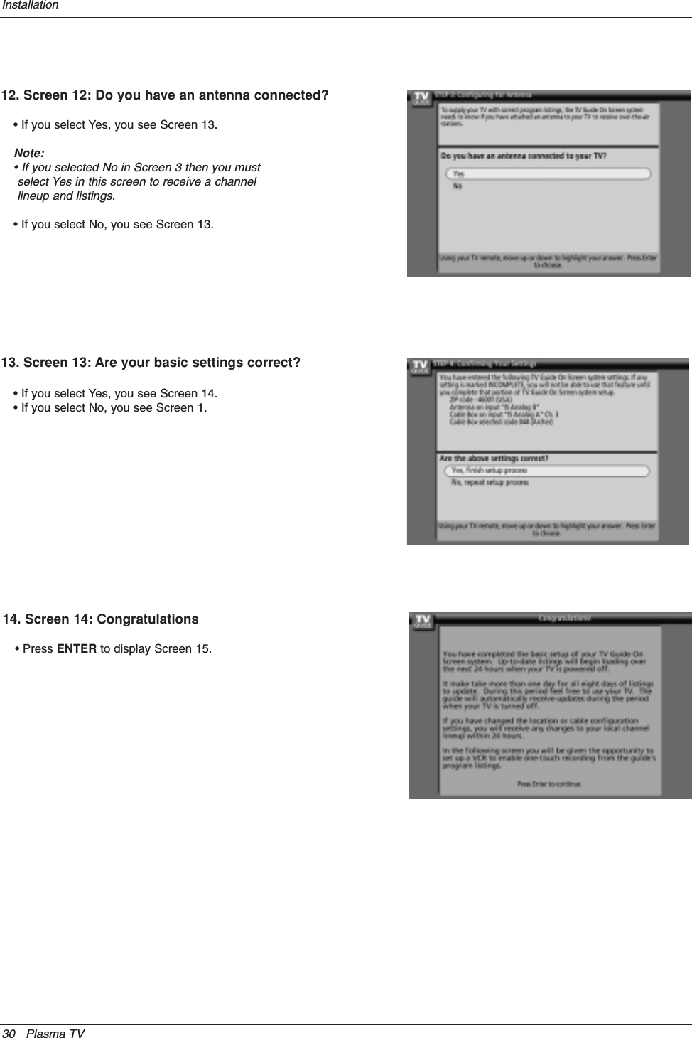
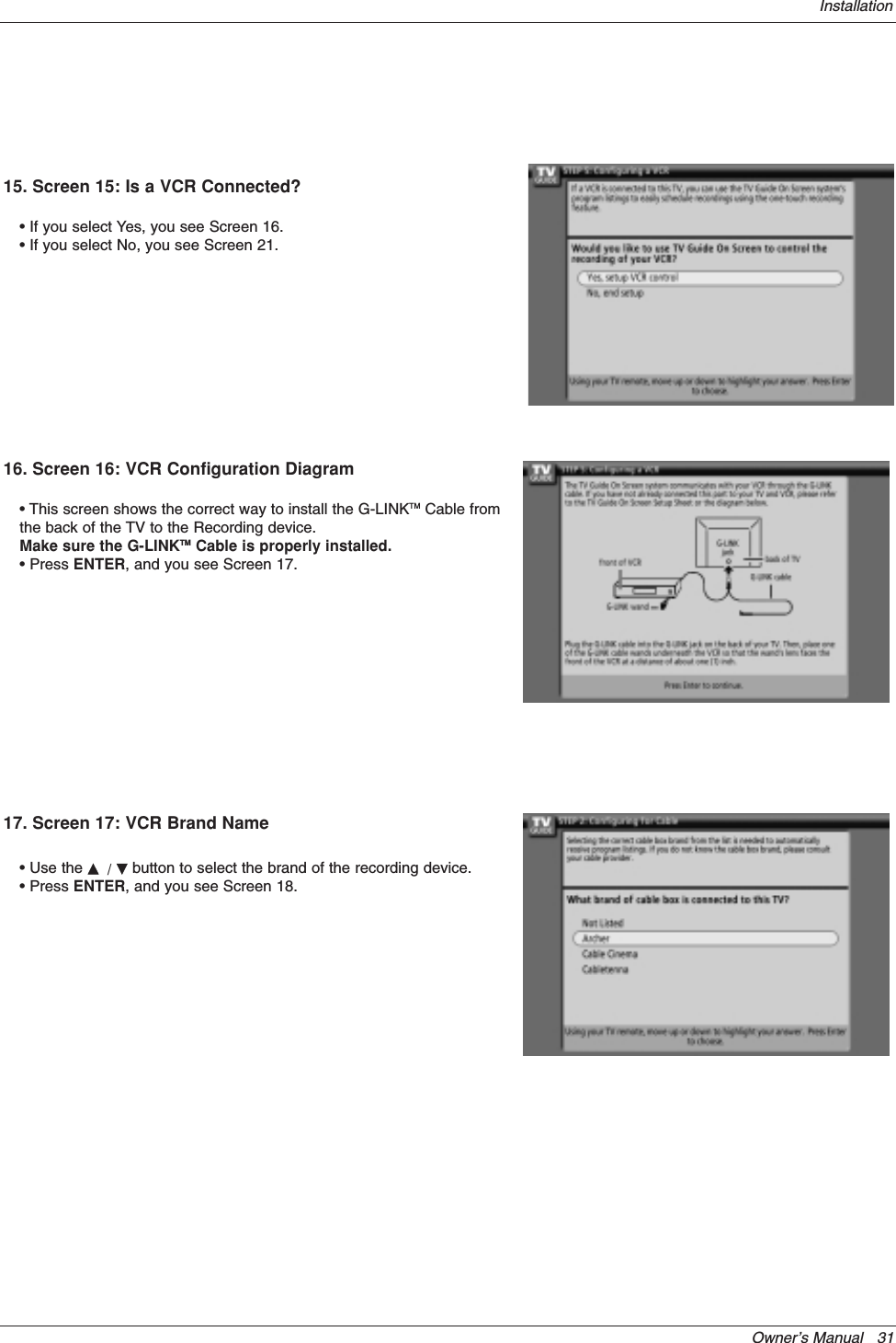
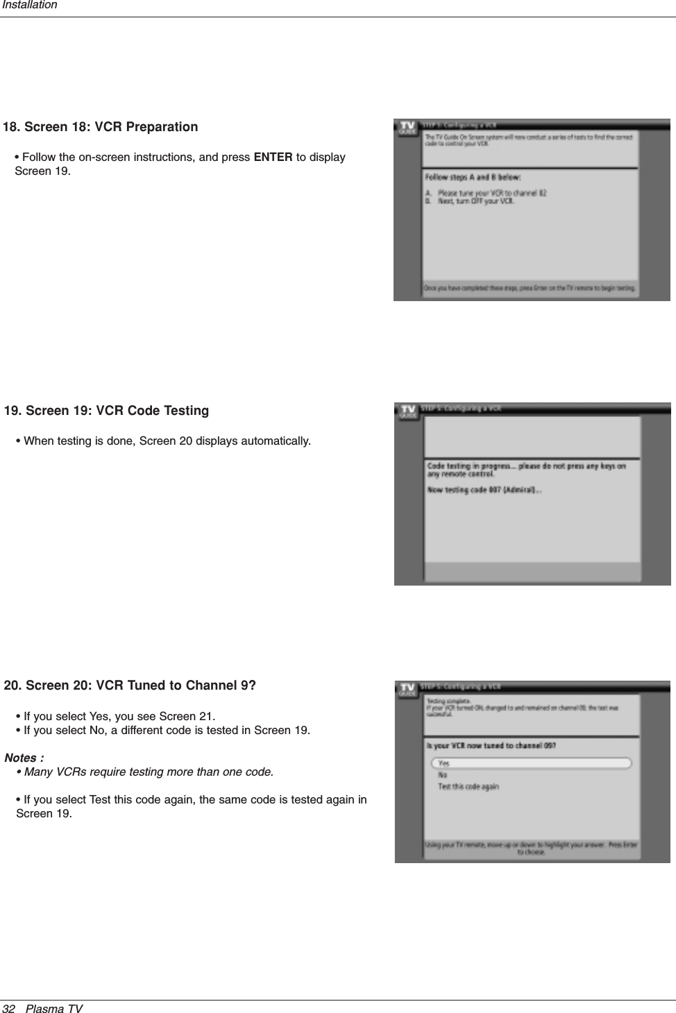
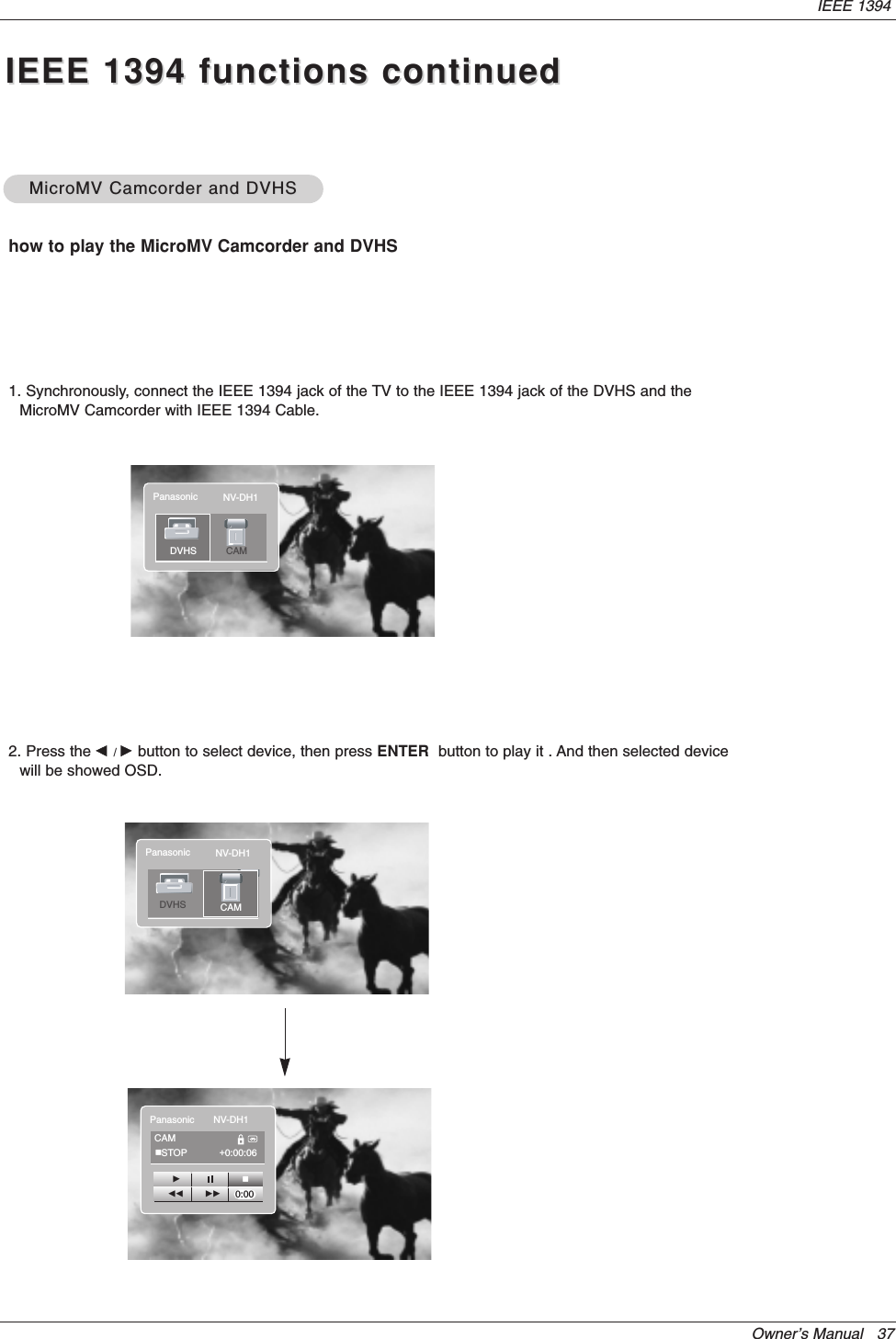
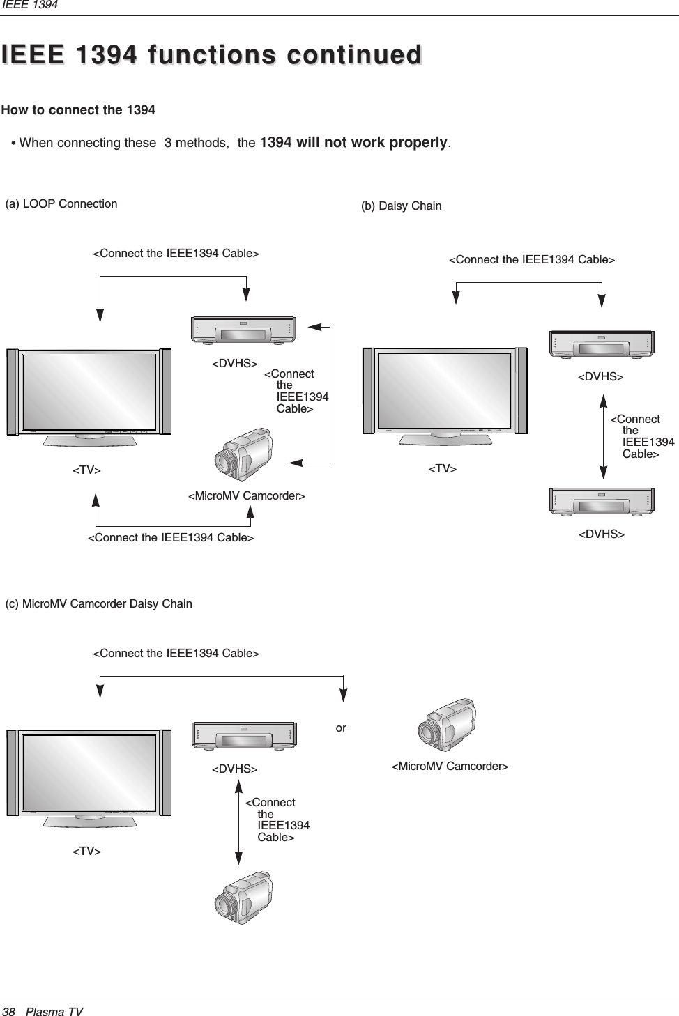
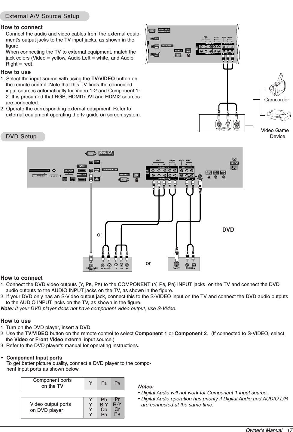
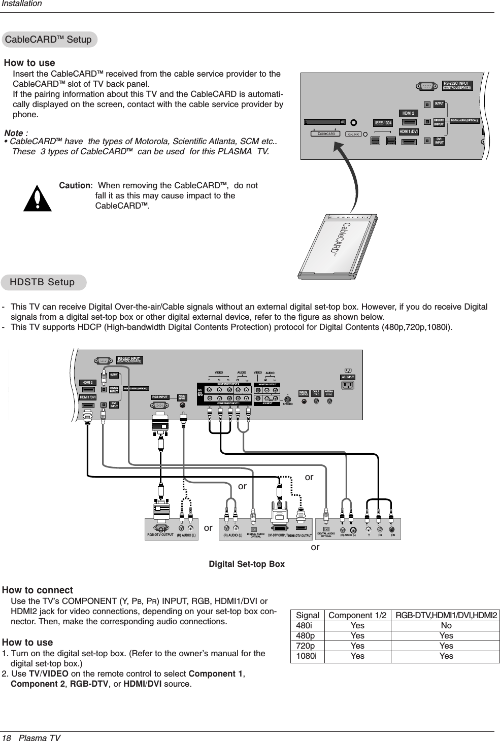
Users Manual Part 1 Revision 2

Please read this manual carefully and completely beforeoperating your TV. Retain this manual for future reference.Record model number and serial number of the TV in thespaces provided below. See the label attached on the back cover and relate thisinformation to your dealer if you require service.Model Number : Serial Number : MODELS:  DU-50PX41S/51SLG Electronics U.S.A., Inc.TMRTruSurround XTPLASMA TVOWNER’S MANUAL
2 Plasma TVWarning/CautionWARNING/CAUTION:TO REDUCE THE RISK OF ELECTRIC SHOCK DO NOT REMOVE COVER (OR BACK). NO USERSERVICEABLE PARTS INSIDE. REFER TO QUALIFIED SERVICE PERSONNEL.The lightning flash with arrowhead symbol, within an equilateral triangle, is intended to alert the user tothe presence of uninsulated “dangerous voltage” within the product’s enclosure that may be of suffi-cient magnitude to constitute a risk of electric shock to persons.The exclamation point within an equilateral triangle is intended to alert the user to the presence ofimportant operating and maintenance (servicing) instructions in the literature accompanying the appli-ance.WARNING/CAUTION:TO PREVENT FIRE OR SHOCK HAZARDS, DO NOT EXPOSE THIS PRODUCT TO RAIN OR MOISTURE.FCC NOTICE• A Class B digital deviceThis equipment has been tested and found to comply with the limits for a Class B digital device, pursuant to Part15 of the FCC Rules. These limits are designed to provide reasonable protection against harmful interference ina residential installation. This equipment generates, uses and can radiate radio frequency energy and, if notinstalled and used in accordance with the instructions, may cause harmful interference to radio communications.However, there is no guarantee that interference will not occur in a particular installation. If this equipment doescause harmful interference to radio or television reception, which can be determined by turning the equipment offand on, the user is encouraged to try to correct the interference by one or more of the following measures:- Reorient or relocate the receiving antenna.- Increase the separation between the equipment and receiver.- Connect the equipment into an outlet on a circuit different from that to which the receiver is connected.- Consult the dealer or an experienced radio/TV technician for help.• Any changes or modifications not expressly approved by the party responsible for compli-ance could void the user’s authority to operate the equipment.CAUTION:Do not attempt to modify this product in any way without written authorization from LG Electronics. Unauthorized mod-ification could void the user’s authority to operate this product.COMPLIANCE:The responsible party for this product’s compliance is:LG Electronics U.S.A., Inc1000 Sylvan Avenue, Englewood Cliffs, NJ  076321-201-816-2000http://www.lgusa.comWARNINGRISK OF ELECTRIC SHOCK        DO NOT OPEN/CAUTIONWARNING/CAUTIONTO REDUCE THE RISK OF FIRE AND ELECTRIC SHOCK, DO NOT EXPOSE THIS PRODUCT TORAIN OR MOISTURE.WWarning/Cautionarning/Caution
Owner’s Manual   3TV Guide On Screen Notices for U.S.A.TV Guide On Screen Notices for U.S.A.In the United States, the TV Guide On Screen system and other related marks are registered marks of Gemstar-TV GuideOn Screen system International, Inc. and/or one of its affiliates. In Canada,TV Guide On Screen system is a registered markof Transcontinental Inc., and is used under license by Gemstar-TV Guide On Screen system International, Inc.The TV Guide On Screen system is protected by one or more of the following issued United States patents 6,498,895,6,418,556, 6,331,877; 6,239,794; 6,154,203; 5,940,073; 4,908,713; 4,751,578; 4,706,121.The TV Guide On Screen system is manufactured under license from Gemstar-TV Guide On Screen system International,Inc. and/or one of its affiliates.Digital Cable CompatibilityDigital Cable CompatibilityThis digital television is capable of receiving basic analog, digital basic and digital premium cable television programming bydirect connection to a cable system providing such programming. A security card provided by your cable operator is requiredto view encrypted digital programming. Certain advanced interactive digital cable services such as video-on-demand, cableoperator enhanced program (For example, electronic program guide provided by the cable operator), and data enhancedtelevision service may require the use of a set top box. For more information contact your local cable operator.Use of the CableCARDTM  TradeMark.“CableCARDTM  is a trademark of Cable Television Laboratories, Inc.”
4 Plasma TVSafety InstructionsIMPORTANT SAFETY INSTRUCTIONSImportant safety instructions shall be provided with each apparatus. This information shall be given in a separate booklet orsheet, or be located before any operating instructions in an instruction for installation for use and supplied with the appara-tus. This information shall be given in a language acceptable to the country where the apparatus is intended to be used. Theimportant safety instructions shall be entitled  “Important Safety Instructions”. The following safety instructions shall be includ-ed where applicable, and, when used, shall be verbatim as follows. Additional safety information may be included by addingstatements after the end of the following safety instruction list. At the manufacturer’s option, a picture or drawing that illus-trates the intent of a specific safety instruction may be placed immediately adjacent to that safety instruction : 1. Read these instructions.2. Keep these instructions.3. Heed all warnings.4. Follow all instructions.5. Do not use this apparatus near water.6. Clean only with dry cloth.7. Do not block any ventilation openings. Install in accordance with the manufacturer’s instructions.8. Do not install near any heat sources such as radiators, heat registers, stoves, or other apparatus (including ampli-fiers)that produce heat.9. Do not defeat the safety purpose of the polarized or grounding-type plug. A polarized plug has two blades withone wider than the other. A grounding type plug has two blades and a third grounding prong, The wide blade or thethird prong are provided for your safety. If the provided plug does not fit into your outlet, consult an electrician forreplacement of the obsolete outlet.10. Protect the power cord from being walked on or pinched particularly at plugs, convenience receptacles, and thepoint where they exit from the apparatus.11. Only use attachments/accessories specified by the manufacturer.12. Use only with the cart, stand, tripod, bracket, or table specified by the manufacturer, or sold with the apparatus.When a cart is used, use caution when moving the cart/apparatus combination to avoid injury from tip-over.Safety InstructionsSafety InstructionsPORTABLE CART WARNING
Owner’s Manual   5Safety Instructions13. Unplug this apparatus during lightning storms or when unused for long periods of time.14. Refer all servicing to qualified service personnel. Servicing is required when the apparatus has been damagedin any way, such as power-supply cord or plug is damaged, liquid has been spilled or objects have fallen into the apparatus, the apparatus has exposed to rain or moisture, does not operate normally, or has been dropped.15. CAUTION concerning the Power Cord :Most appliances recommend they be placed upon a dedicated circuit; thatis, a single outlet circuit which powers only that appliance and has noadditional outlets or branch circuits. Check the specification page ofthis owner's manual to be certain.Do not overload wall outlets. Overloaded wall outlets, loose or damagedwall outlets, extension cords, frayed power cords, or damaged orcracked wire insulation are dangerous. Any of these conditions couldresult in electric shock or fire. Periodically examine the cord of yourappliance, and if its appearance indicates damage or deterioration,unplug it, discontinue use of the appliance, and have the cord replacedwith an exact replacement part by an authorized servicer.Protect the power cord from physical or mechanical abuse, such as beingtwisted, kinked, pinched, closed in a door, or walked upon. Payparticular attention to plugs, wall outlets, and the point where thecord exits the appliance.16. Outdoor Use Marking :WARNING - To Reduce The Risk Of Fire Or Electric Shock, Do Not Expose This Appliance To Rain Or Moisture.17. Wet Location Marking :Apparatus shall not be exposed to dripping or splashing and no objects filled with liquids, such as vases, shallbe placed on the apparatus.Safety Instructions continuedSafety Instructions continued
6 Plasma TVContentsAfter reading this manual, keep it handy for future reference.Warning/Caution  . . . . . . . . . . . . . . . . . . . . . . . . . . . . . . . .2Digital Cable Compatibility . . . . . . . . . . . . . . . . . . . . . . . . .3Safety Instructions . . . . . . . . . . . . . . . . . . . . . . . . . . . . .4~5IntroductionControls  . . . . . . . . . . . . . . . . . . . . . . . . . . . . . . .8Connection Options  . . . . . . . . . . . . . . . . . . . . . .9Remote Control Key Functions . . . . . . . . . . 10~11InstallationInstallation Instructions  . . . . . . . . . . . . . . . . . .13~14Joining the TV assembly to the wall to protect the set tumbling . . . . . . . . . . . . . . . . . . . . . . . . . . . . . . . . .13Arrangement wires  . . . . . . . . . . . . . . . . . . . . . . . .13External Equipment Connections  . . . . . . . . . .15~20Antenna or Cable Connection  . . . . . . . . . . .15~16VCR Setup   . . . . . . . . . . . . . . . . . . . . . . . . . . .16External A/V Source Setup  . . . . . . . . . . . . . . . .17DVD Setup  . . . . . . . . . . . . . . . . . . . . . . . . . . . .17CableCARDTM Setup  . . . . . . . . . . . . . . . . . . . . .18HDSTB Setup   . . . . . . . . . . . . . . . . . . . . . . . . .18PC Setup  . . . . . . . . . . . . . . . . . . . . . . . . . . . . .19Monitor Out Setup  . . . . . . . . . . . . . . . . . . . . . .20Digital Audio Output  . . . . . . . . . . . . . . . . . . . . .20HDMI1/DVI (VIDEO), HDMI2  . . . . . . . . . . . . .21~23TV Guide On Screen Setup  . . . . . . . . . . . . . .24~33IEEE 1394 . . . . . . . . . . . . . . . . . . . . . . . . . . . . . . . .34~38TV Guide On ScreenTM System  . . . . . . . . . . . . .39~57OperationScreen Setup for PC modeAdjustments for screen Position, Size, and Phase . .58On-screen Menus Language Selection  . . . . . . . . .59Setup Menu OptionsEZ Scan (Channel Search)  . . . . . . . . . . . . . . . .60Manual Scan   . . . . . . . . . . . . . . . . . . . . . . . . . .60Channel Edit . . . . . . . . . . . . . . . . . . . . . . . . . . .61DTV Signal Strength  . . . . . . . . . . . . . . . . . . . . .61Channel Label Setup  . . . . . . . . . . . . . . . . . . . .62Main Picture Source Selection  . . . . . . . . . . . . .62Input Edit  . . . . . . . . . . . . . . . . . . . . . . . . . . . . .62Video Menu OptionsEZ Picture  . . . . . . . . . . . . . . . . . . . . . . . . . . . .63Manual Picture Control (Custom Option)  . . . . . .63Color Temperature Control  . . . . . . . . . . . . . . . .63Video Preset   . . . . . . . . . . . . . . . . . . . . . . . . . .63Audio Menu OptionsAudio Language  . . . . . . . . . . . . . . . . . . . . . . . .64EZ SoundRite / EZ Sound . . . . . . . . . . . . . . . . .64Manual Sound Control (Custom Option)  . . . . . .64Front Surround  . . . . . . . . . . . . . . . . . . . . . . . . .65BBE  . . . . . . . . . . . . . . . . . . . . . . . . . . . . . . . . .65TV Speakers On/Off Setup  . . . . . . . . . . . . . . . .66Stereo/SAP Broadcasts Setup  . . . . . . . . . . . . .66Time Menu OptionsAuto Clock Setup  . . . . . . . . . . . . . . . . . . . . . . .67Manual Clock Setup  . . . . . . . . . . . . . . . . . . . . .67On/Off Timer Setup   . . . . . . . . . . . . . . . . . . . . .67Sleep Timer / Auto Off . . . . . . . . . . . . . . . . . . . .68Option Menu FeaturesAspect Ratio Control . . . . . . . . . . . . . . . . . . . . .69Cinema 3:2 Mode Setup  . . . . . . . . . . . . . . . . . .69Caption . . . . . . . . . . . . . . . . . . . . . . . . . . . . . . .70Caption / Text  . . . . . . . . . . . . . . . . . . . . . . . . . .70Caption Option   . . . . . . . . . . . . . . . . . . . . . . . .71ISM Method  . . . . . . . . . . . . . . . . . . . . . . . . . . .72Low Power  . . . . . . . . . . . . . . . . . . . . . . . . . . . .73Auto Demo  . . . . . . . . . . . . . . . . . . . . . . . . . . . .73Freeze & Magnify  . . . . . . . . . . . . . . . . . . . . . . .73Lock Menu OptionsParental Lock Setup  . . . . . . . . . . . . . . . . . . . . .75CableCARDTM FunctionCable menu options  . . . . . . . . . . . . . . . . . . . . .76Scrambled channel . . . . . . . . . . . . . . . . . . . . . .76Cable Channel List  . . . . . . . . . . . . . . . . . . . . . .77Emergency Alert Message  . . . . . . . . . . . . . . . .77Remote ControlPIP (Picture-in-Picture)/Twin Picture  . . . . . . . . . ..78Watching PIP/POP/Twin Picture . . . . . . . . . . . ..78Selecting an Input Signal Source for PIP/Twin Picture . .78Swapping PIP/Twin Picture  . . . . . . . . . . . . . . . .78TV Program Selection for PIP  . . . . . . . . . . . . . .78Moving the PIP sub picture  . . . . . . . . . . . . . . . .79Adjusting Main and Sub Picture Sizes for Twin Picture . .79POP (Picture-out-of-Picture: Channel Scan)  . . .79X STUDIO . . . . . . . . . . . . . . . . . . . . . . . . . . .80~82Brief Info.  . . . . . . . . . . . . . . . . . . . . . . . . . . . . . . .83EZ Mute  . . . . . . . . . . . . . . . . . . . . . . . . . . . . . . . .84External Control Device Setup  . . . . . . . . . . . . . . . .85~90IR Codes    . . . . . . . . . . . . . . . . . . . . . . . . . . . . . . . .91~92Programming the Remote   . . . . . . . . . . . . . . . . . . . . . .93Programming Codes    . . . . . . . . . . . . . . . . . . . . . . .94~95Troubleshooting Checklist  . . . . . . . . . . . . . . . . . . . . . .96Maintenance  . . . . . . . . . . . . . . . . . . . . . . . . . . . . . . . . .97Product Specifications  . . . . . . . . . . . . . . . . . . . . . . . . .98Warranty   . . . . . . . . . . . . . . . . . . . . . . . . . . . . . . . .99~100ContentsContentsSetup and Operation ChecklistSetup and Operation ChecklistSetup and Operation Checklist(See pages 13~20 for available connection and operational setup options.)1. Unpack TV and all accessories.2. Connect all external video and audio equipment.see pages 15~20.3 Install batteries in remote control.See page 12.4. Turn TV on.See page 59.5. Turn video source equipment on.6. Select viewing source for TV.See pages 62.7. Fine-tune source image and sound to your personal prefer-ence or as required by source. See pages 63~ 66.8. Additional features set upSee Contents above.
Owner’s Manual   7IntroductionIntroductionIntroductionWhat is a Plasma Display Panel (PDP)?A plasma display panel is the latest display technology and the best way to achieve flat panel displays with excellent image qualityand large screen sizes that are easily viewable. The PDP can be thought of as a descendant of the neon lamp and it can be alsobe viewed as a series of fluorescent lamps. How does it work?PDP is an array of cells, known as pixels, which are comprised of 3 sub pixels, corresponding to the colors red, green, and blue.Gas in a plasma state is used to react with phosphors in each sub-pixel to produce colored light (red, green, or blue). These phos-phors are the same types used in Cathode Ray Tube (CRT) devices such as televisions and common computer monitors.You get the rich, dynamic colors that you expect. Each sub-pixel is individually controlled by advanced electronics to produce over16 million different colors. All of these mean that you get perfect images that are easily viewable in a display that is less than 5inches thick. 160° - Wide angle range of visionYour flat panel plasma screen offers an exceptionally broad viewing angle -- over 160 degrees. This means that the display isclear and visible to viewers anywhere in the room who can see the screen. Wide ScreenThe screen of the Plasma Display is so wide that your viewing experience is as if you are in a theater. MultimediaConnect your plasma display to a PC and you can use it for conferencing, games, and Internet browsing. The Picture-in-Picturefeature allows you to view your PC and video images simultaneously.VersatileThe light weight and thin size makes it easy to install your plasma display in a variety of locations where conventional TVs will notfit.The PDP Manufacturing Process: a few minute colored dots may be present on the PDP screenThe PDP (Plasma Display Panel), which is the display device of this product, is composed of 0.9 to 2.2 million cells. A few celldefects will normally occur in the PDP manufacturing process. Several tiny, minute colored dots visible on the screen should beacceptable. This also occurs in other PDP manufacturers' products. The tiny dots appearing does not mean that this PDP is defec-tive. Thus a few cell defects are not sufficient cause for the PDP to be exchanged or returned. Our production technology mini-mizes these cell defects during the manufacture and operation of this product. Cooling Fan NoiseIn the same way that a fan is used in a PC computer to keep the CPU (Central Processing Unit) cool, the PDP is equipped withcooling fans to cool the Monitor and improve its reliability. Therefore, a certain level of noise could occur while the fans are operat-ing and cooling the PDP.The fan noise doesn't have any negative effect on the PDP's efficiency or reliability. The noise from these fans is normal during theoperation of this product. We hope you understand that a certain level of noise from the cooling fans is acceptable and is not suffi-cient cause for the PDP to be exchanged or returned.
8 Plasma TVIntroductionTV GUIDETV GUIDEControlsControls- This is a simplified representation of front panel. Here shown may be somewhat different from your TV.Front Panel ControlsFront Panel ControlsMENU ButtonTV/VIDEO ButtonVOLUME (F,G) ButtonsCHANNEL (E, D) ButtonsINDEXSwitchesLED Displayon or off.TV GUIDE ButtonRemote ControlSensorPower IndicatorIlluminates orange instandby mode,Illuminates green whenthe TV is turned on.(If power isn’t turn on inred, contact your servicecenter.)POWER Button
RS-232C INPUT(CONTROL/SERVICE)AUDIO RLDIGITAL AUDIO (OPTICAL)DVI INPUTCOMPONENT2 INPUTOUTPUTAUDIO INPUTRGB INPUTVIDEO HDMI 2HDMI1/DVICOMPONENT INPUT 1RL(MONO)CABLE ANTENNA AC  INPUTDVD  /DTVINPUTIEEE-1394COMPONENT INPUT 2MONITOR OUTPUTA/V INPUT VIDEO AUDIO CableS-VIDEOREMOTECONTROLS-VIDEO    FRONTA/V INPUTVIDEO  L / MONO AUDIO R Owner’s Manual   9IntroductionConnection OptionsConnection OptionsBack Connection PanelBack Connection PanelS-VIDEO InputA connection available to provide bet-ter picture quality than the video input.Memory Card SlotsG-LINKTMConnect an IRcontroller to thisjack.CableCARD™Used forCableCARD™received from CableService Provider.VIDEO InputConnects the video signal from avideo device.AUDIO InputUse to connect to hear stereo soundfrom an external device.Antenna  InputsConnect antennasignals to the TV.RGB/AUDIO INPUTConnect the monitor outputconnector from a PC to theappropriate input port.Digital Audio (DVI: DigitalVisualInterface/Component2)Input/Digital Audio OutputConnect  digital audio fromvarious types of equipment.Note: In standby mode, these ports will not work.DVD/DTV Input(Component 1-2)Connect a DVHS, aMicroMV Camcorder, ora Set-Top Box to one ofIEEE1394 connectors.Monitor OutputConnect a secondTV or Monitor.Remote Control PortConnect your wiredremote control here.S-Video InputConnect S-Video out froman S-VIDEOdevice to the S-VIDEO input.CABLE InputsConnect cable signals to theTV, either directly or throughyour cable box.RS-232C INPUT (CON-TROL/SERVICE) PORTConnect to the RS-232Cport on a PC.HDMI1/DVI, HDMI 2Connect a HDMI sig-nal to HDMI1/DVI orHDMI2. Or connect aDVI(Video) signal toHDMI1/DVI.Audio/Video InputConnect audio/videooutput from anexternal device tothese jacks.Power Cord SocketThis TV operates on an AC power. The voltageis indicated on the Specifications page. Neverattempt to operate the TV on DC power.IEEE1394Connect DVHS orMicroMV to IEEE1394Connector.
10 Plasma TVInstallation- When using the remote control, aim it at the remote control sensor on the TV.MODEDAY -DAY +FLASHBKAPMCC1394FREEZETV INPUT TV/VIDEOM/C EJECTAUTO DEMOEXITRemote Control Key FunctionsRemote Control Key FunctionsTV INPUTWhen you watch the TV, Antenna andCable is toggled. In Video, Front Video,Component 1-2, RGB-DTV (or RGB-PC),HDMI1/DVI, HDMI2 and IEEE1394 inputsources, screen return to the last TV chan-nel.MUTESwitches the sound on or off.(Refer to p.84)MODESelects the remote operating mode: TV,DVD, VCR, AUDIO, CABLE or STB. Selecta mode other than TV, for the remote tooperate an external device.FLASHBKTunes to the recent channels.EXITClears all on-screen displays and returns toTV viewing from any menu.TIMER Lets you select the amount of time beforeyour TV turns itself off automatically.MENUBrings up the main menu to the screen.Enters or exits a Panel Menu in the TV GuideOn Screen system.PIPSwitches between PIP, POP (Picture-out-of-Picture) and Twin picture modes.Switches the video window locking orunlocking in the Listings Grid.PIPCH-/PIPCH+Changes to the next higher/lower PIPchannel.PIP INPUTSelects the input source for the sub pic-ture in PIP/Twin picture mode.SWAPExchanges the main/sub images inPIP/Twin picture mode.EZ PICSelects a factory preset picture modedepending on the viewing environment.ADJUSTAdjusts screen position, size, and phase inPC mode.FREEZEFreezes the currently-viewed picture. Mainpicture is frozen in PIP/Twin picture mode.TV/VIDEOWhen you watch the TV, screen  return tothe last external ( Video, Front Video,Component 1-2, RGB-DTV (or RGB-PC),HDMI1/DVI, HDMI2) input.Selects:  Video, Front Video, Component1-2, RGB-DTV (or RGB-PC),  HDMI1/DVIand HDMI2 input sources.(Only when the jack connects ,  Video,Front Video, Component 1-2 inputsources are linked automatically)TV GUIDEBrings up the TV Guide On Screen systemto the screen.MarkSelects a photo or music you want to viewor play in Xstudio mode.INFOWhen you watch the TV, information dis-plays  on top of the screen. Not available inComponent 1-2, RGB, HDMI1/DVI andƒHDMI2 mode.(Refer to p.83)FAVScroll the Favorite channels.AUTO DEMODisplays the slide show to explain the mainfeatures of this TV.
Owner’s Manual   11DAY+/DAY-Moves forward or backward in 24 hourincrements in the Listings Grid.- When using the remote control, aim it at the remote control sensor on the TV.Remote Control Key FunctionsRemote Control Key FunctionsMODEDAY -DAY +FLASHBKAPMCC1394FREEZETV INPUT TV/VIDEOM/C EJECTAUTO DEMOEXITNUMBER buttonsVCR/DVD BUTTONS• Control some video cassette recordersor DVD players. ("RECORD" button is notavailable for DVD players.)< Only TV mode >•In Photo mode of Xstudio, the view statechanges to the slide show state with“PLAY” button and the slide show statechanges to the view state with “PAUSE”button.• In Music mode of Xstudio, controls themusic with “PAUSE”, “STOP”, ”PLAY”,”(Left/Right) SKIP” buttons. Note that FFand REW do not work in the mode.•Control the DVHS or Camcorder of IEEE1394 mode. RATIOChanges the aspect ratio.POWERTurns your TV or any other programmedequipment on or off, depending on mode.CCSelect a closed caption:Off, CC1~4, Text1~4.THUMBSTICK (Up/Down/Left/Right/ENTER)Allows you to navigate the on-screen menusand  adjust the system settings to your pref-erence.CHANNEL UP/DOWNSelects available channels found with EZscan.PAGE UP/PAGE DOWNMoves from one full set of screen infor-mation to the next one.SAPSelects MTS sound: Mono, Stereo, andSAP in Analog mode. Change the audio lan-guage in DTV mode. EZ SOUNDSelects the sound appropriate for theprogram's character.LIGHTIlluminates the remote controlbuttons.APM (Adaptive Picture Mode)Concurrently, compare  with the Daylight,Normal, Night Time and Custom onthe screen.VOLUME UP/DOWNIncreases/decreases the sound level.1394  (Refer to p.34-38)Bring  up the menu to select the Photo orMusic mode of Xstudio for memory cards.M/C EJECTWhen removing the Memory Card,this button is used.ENTERVOL CHPOWER(북미)ENTERVOL CHPOWER(북미)확인방송안내메뉴조용히이전채널선호채널취소예약목록녹화목록음량 채널동시화면취침예약 화면크기 화면조정 주/부전환음성다중 자막방송영상파레트부채널 부채널 부화면입력방송보기입력외부입력전원제품선택페이지페이지선택TN-60/50PY20TN-42PX40X(한국) DN-42PX40X(한국)확인방송안내메뉴화면크기조용히이전채널선호채널취소1394영상파레트음량 채널동시화면화면조정음성다중자막방송 자동음성 주/부전환부채널 부채널 부화면입력입력외부입력전원제품선택페이지페이지취침예약자동음성
12 Plasma TVInstallationInstallationInstallationOwner’s Manual1.5V1.5VBatteries Power CordMODEDAY -DAY +FLASHBKAPM   CCAUTO DEMOM/C EJECTTV INPUT TV/VIDEO75ΩRound CableEnsure that the following accessories are included with your plasma display. If an accessory is missing, please contact the dealerwhere you purchased the product.- Secure the TV assembly by joining it to a wall by using the TV/Wall brackets.Joining the TV assembly to the wall to protect the set tumbling•  After the set must be mounted on the desk top, install theTV brackets on the TV as shown.Install the TV brackets on the TV as shown.Insert the 2 bolts and tighten securely, in the upper holeson the bracket. Install the wall brackets on the wall with 4 bolts*, (notsupplied with the product), as shown.Match the height of the TV brackets and the wall brack-ets. Check to be sure the brackets are tightened securely.• Secure the TV assembly to the wall with strong stringsor wound wire cables, (not supplied with the product), asshown.2-Wall brackets 2-TV bracket bolts G-LINK CableRemote ControlInstalling Batteries• Open the battery compartment cover on the back side and install the batteriesmatching correct polarity (+ with +, - with -).• Install two 1.5V AA batteries. Don’t mix old or used batteries with new ones.Replace cover.D-sub 15 pin Cable
Owner’s Manual   13Swivel functionSwivel functionInstallation InstructionsInstallation Instructions•After installing the TV, you can adjust the the TV set manually to the left or right direction by 20 degrees to suit your viewingposition.Note: Before adjusting the angle, you must loosen (to the left) the shaft bolt on the middle of stand’s back. And when stand be level with TV,  you must close (to the right) the shaft bolt to set the hole.Arrangement wiresArrangement wires•Run the accessory device wires  inside the JACK MANAGEMENT pole as shown.
14 Plasma TVInstallationInstallation InstructionsInstallation InstructionsGROUNDINGEnsure that you connect the grounding / earth wire to prevent possibleelectric shock. If grounding methods are not possible, have a qualifiedelectrician install a separate circuit breaker. Do not try to ground theunit by connecting it to telephone wires, lightening rods, or gas pipes.PowerSupplyShort-circuitBreaker4 inches4 inches4 inches4 inches2 inchesWWall Mount: Horizontal installationall Mount: Horizontal installationFor proper ventilation, allow a clearance of 4” on eachside and 2” from the wall. Detailed installation instruc-tions are available from your dealer, see the optionalWall Mounting Bracket Installation.4 inches4 inches2.36 inches4 inches2 inchesDesktop Pedestal InstallationDesktop Pedestal InstallationFor proper ventilation, allow a clearance of 4” on eachside and the top, 2.36” on the bottom, and 2” from thewall. Detailed installation instructions are included inthe optional Desktop Stand Installation.•The TV can be installed in various ways such as on a wall, or on a desktop etc.•The TV is designed to be mounted horizontally.
Owner’s Manual   15InstallationAntenna or Cable ConnectionAntenna or Cable ConnectionExternal Equipment ConnectionsExternal Equipment Connections- Wall Antenna Socket or Outdoor Antenna without a Cable Box Connections- For optimum picture quality, adjust antenna direction if needed.1. Analog and Digital TV signals provided on antenna2. Analog and Digital TV signals provided on cableCABLE ANTENNA AC  INPUTMulti-family Dwellings/Apartments(Connect to wall antenna socket)Single-family Dwellings /Houses(Connect to wall jack for outdoor antenna)OutdoorAntennaWall AntennaSocketVHF AntennaUHF AntennaRF Coaxial Wire (75 ohm)Bronze WireTurn clockwise to tighten.Bronze WireBe careful not to bend the bronze wire whenconnecting the antenna.Bronze WireCable TV WallJack RF Coaxial Wire (75 ohm)CABLE ANTENNA REMOTECONTROL
16 Plasma TVInstallation- To avoid picture noise (interference), leave an adequate distance between the VCR and TV- Use the ISM Method (on the Option menu) feature to avoid having a fixed image remain on the screen for a long period of time.If the 4:3 picture format is used; the fixed images on the sides of the screen may remain visible on the screen.Connection Option 1Set VCR output switch to channel 3 or 4 andthen tune the TV to the same channel number.Connection Option 21. Connect the audio and video cables from theVCR's output jacks to the TV input jacks, asshown in the figure. When connecting the TV to VCR, match thejack colors (Video = yellow, Audio Left = white,and Audio Right = red).If you connect an S-VIDEO output from VCR tothe S-VIDEO input, the picture quality isimproved; compared to connecting a regularVCR to the Video input.2. Insert a video tape into the VCR and pressPLAY on the VCR. (Refer to the VCR owner’smanual.) 3. Select the input source with using theTV/VIDEO button on the remote control. Notethat this TV finds the connected input sourcesautomatically for Video, Front Video andComponent 1-2. It is presumed that RGB,HDMI1/DVI and HDMI2 sources are connected.Do not connect to both Video andS-Video at the same time.VCR SetupVCR SetupTCE)AUDIO RL(OPTICAL)RGB INPUTVIDEO COMPONENT INPUT 1RL(MONO)  CABLE ANTENNA AC  INPUTDVD  /DTVINPUTCOMPONENT INPUT 2MONITOR OUTPUTA/V INPUT VIDEO AUDIO S-VIDEO OUTIN(R) AUDIO (L) VIDEO34OUTPUTSWITCHANT OUTANT INAUDIO INPUTS-VIDEOREMOTECONTROLVCR Rear12•In a poor signal area to improve picture quality, purchaseand install a signal amplifier.•If the antenna needs to be split for two TV’s, install a “2-Way Signal Splitter” in the connections.•If the antenna is not installed properly, contact your deal-er for assistance.CABLE ANTENNA SignalAmplifier3. Analog and Digital TV signals provided on cable and antennaAntennaRF Coaxial Wire (75 ohm)Bronze WireTurn clockwise to tighten.Cable TV WallJack RF Coaxial Wire (75 ohm)CABLE ANTENNA AC  INPUT
Owner’s Manual   17•Component Input portsTo get better picture quality, connect a DVD player to the compo-nent input ports as shown below.How to connectConnect the audio and video cables from the external equip-ment's output jacks to the TV input jacks, as shown in thefigure. When connecting the TV to external equipment, match thejack colors (Video = yellow, Audio Left = white, and AudioRight = red).How to use1. Select the input source with using the TV/VIDEO button onthe remote control. Note that this TV finds the connectedinput sources automatically for Video 1-2 and Component 1-2. It is presumed that RGB, HDMI1/DVI and HDMI2 sourcesare connected.2. Operate the corresponding external equipment. Refer toexternal equipment operating the tv guide on screen system.Component ports on the TV YPBPRVideo output ports on DVD playerYYYYPbB-YCbPBPrR-YCrPRHow to connect1. Connect the DVD video outputs (Y, PB, PR) to the COMPONENT (Y, PB, PR) INPUT jacks  on the TV and connect the DVDaudio outputs to the AUDIO INPUT jacks on the TV, as shown in the figure.2. If your DVD only has an S-Video output jack, connect this to the S-VIDEO input on the TV and connect the DVD audio outputsto the AUDIO INPUT jacks on the TV, as shown in the figure.Note: If your DVD player does not have component video output, use S-Video.How to use1. Turn on the DVD player, insert a DVD.2. Use the TV/VIDEO button on the remote control to select Component 1 or Component 2.  (If connected to S-VIDEO, selectthe Video or Front Video external input source.)3. Refer to the DVD player's manual for operating instructions.External External A/V Source SetupA/V Source SetupDVD SetupDVD SetupRS-232C INPUT(CONTROL/SERVICE)AUDIO RLDIGITAL AUDIO (OPTICAL)DVI INPUTCOMPONENT2 INPUTOUTPUTRGB INPUTVIDEO HDMI 2HDMI /DVICOMPONENT INPUT 1RL(MONO)V IDEO  SREMOTE  CONTROLCABLE ANTENNA AC  INPUTDVD  /DTVINPUTCOMPONENT INPUT 2MONITOR OUTPUTA/V INPUT VIDEO AUDIO RLAUDIO VIDEOAUDIO INPUTRS-232C INPUT(CONTROL/SERVICE)AUDIO RLDIGITAL AUDIO (OPTICAL)DVI INPUTCOMPONENT2 INPUTOUTPUTRGB INPUTVIDEO HDMI 2HDMI1 /DVICOMPONENT INPUT 1RL(MONO)     CABLE ANTENNA AC  INPUTDVD  /DTVINPUTIEEE-1394COMPONENT INPUT 2MONITOR OUTPUTA/V INPUT VIDEO AUDIO CableBR(R) AUDIO (L)DIGITAL AUDIOOPTICAL(R) AUDIO (L)S-VIDEOAUDIO INPUTS-VIDEOREMOTECONTROLDVDorCamcorderVideo GameDeviceNotes:• Digital Audio will not work for Component 1 input source.• Digital Audio operation has priority if Digital Audio and AUDIO L/Rare connected at the same time.or
18 Plasma TVInstallation- This TV can receive Digital Over-the-air/Cable signals without an external digital set-top box. However, if you do receive Digitalsignals from a digital set-top box or other digital external device, refer to the figure as shown below.- This TV supports HDCP (High-bandwidth Digital Contents Protection) protocol for Digital Contents (480p,720p,1080i).How to connectUse the TV’s COMPONENT (Y, PB, PR) INPUT, RGB, HDMI1/DVI orHDMI2 jack for video connections, depending on your set-top box con-nector. Then, make the corresponding audio connections.How to use1. Turn on the digital set-top box. (Refer to the owner’s manual for thedigital set-top box.) 2. Use TV/VIDEO on the remote control to select Component 1,Component 2, RGB-DTV, or HDMI/DVI source.HDSTB SetupHDSTB SetupRS-232C INPUT(CONTROL/SERVICE)AUDIO RLDIGITAL AUDIO (OPTICAL)DVI INPUTCOMPONENT2 INPUTOUTPUTRGB INPUTVIDEO HDMI 2HDMI1 /DVICOMPONENT INPUT 1RL(MONO)  CABLE ANTENNA AC  INPUTDVD  /DTVINPUTIEEE-1394COMPONENT INPUT 2MONITOR OUTPUTA/V INPUT VIDEO AUDIO Cable(R) AUDIO (L)RGB-DTV OUTPUTBR(R) AUDIO (L)DIGITAL AUDIOOPTICAL(R) AUDIO (L)DVI-DTV OUTPUTDIGITAL AUDIOOPTICALHDMI-DTV OUTPUTAUDIO INPUTS-VIDEOREMOTECONTROLDigital Set-top BoxororororSignal480i480p720p1080iComponent 1/2YesYesYesYesRGB-DTV,HDMI1/DVI,HDMI2NoYesYesYesCableCARDCableCARDTMTM SetupSetupRS-232C INPUT(CONTROL/SERVICE)DIGITAL AUDIO (OPTICAL)DVI INPUTCOMPONENT2 INPUTOUTPUTRGB INPHDMI 2HDMI1 /DVIIEEE-1394CableHow to useInsert the CableCARDTMTM received from the cable service provider to theCableCARDTMTM slot of TV back panel. If the pairing information about this TV and the CableCARD is automati-cally displayed on the screen, contact with the cable service provider byphone.Note :• CableCARDTMTM have  the types of Motorola, Scientific Atlanta, SCM etc..These  3 types of CableCARDTMTM can be used  for this PLASMA TV.Caution:  When removing the CableCARDTMTM,  do notfall it as this may cause impact to theCableCARDTMTM.or
Owner’s Manual   19<When the PC supports DVI>How to connect1. Connect the PC to HDMI1/DVI port of this TV with an HDMI-to-DVI cable(not supplied with this product).If you do not need to connect audio, HDMI2 port is also available for the DVI video connection.2. If the PC(or the sound card of the PC) has a fiber optic digital audio output connector, connect the PC's audio output  to DIGI-TAL AUDIO(OPTICAL) port for DVI INPUT.3. If the PC(or the sound card of the PC) has an analog audio output connector, connect the PC's audio output  to AUDIO INPUTport located on the right side of RGB INPUT port.How To Use1. To get the best picture quality, adjust the PC graphics card to 1024x768, 60Hz.2. Select HDMI1/DVI input source in main input option of SETUP menu.(Refer to P.62)TV/VIDEO button is also available for this purpose.3. Check the image on your TV. There may be noise associated with the resolution, vertical pattern, contrast or brightness in PCmode. If noise is present, change the PC output to another resolution, change the refresh rate to another rate or adjust thebrightness and contrast on the VIDEO menu  until the picture is clear. If the refresh rate of the PC graphic card can not bechanged, change the PC graphic card or consult the manufacturer of the PC graphic card.<When the PC supports RGB>How to connect1. Connect the PC to RGB INPUT port of this TV with a RGB cable.2. If the PC(or the sound card of the PC) has an analog audio output connector, connect the PC's audio output to AUDIO INPUTport located on the right side of RGB INPUT port.How To Use1. To get the best picture quality, adjust the PC graphics card to 1024x768, 60 Hz.2. Select RGB-PC  input source in main input option of SETUP menu.(Refer to P.57)Once you select RGB-PC in main input option of SETUP menu, TV/VIDEO button is also available for this purpose.3. Check the image on your TV. There may be noise associated with the resolution, vertical pattern, contrast or brightness in PCmode. If noise is present, change the PC output to another resolution,  change the refresh rate to another rate or adjust thebrightness and contrast on the VIDEO menu  until the picture is clear. If the refresh rate of the PC graphic card can not bechanged, change the PC graphic card or consult the manufacturer of the PC graphic card.720x400InstallationPC SetupPC Setup- This TV provides Plug and Play capability, meaning that the PC adjusts automatically to the TV's settings. - The TV perceives 640x480, 60Hz as DTV 480p based on the PC graphic card, change the screen scanning rate for the graphiccard accordingly.800x60070.0885.0359.9472.8075.0085.0035.15637.87948.07746.87553.67448.36356.47660.02356.2560.3172.1875.0085.0660.0070.0675.02VerticalFrequency(Hz) Resolution HorizontalFrequency(KHz) VerticalFrequency(Hz)1024x768Resolution640x480HorizontalFrequency(KHz)31.46937.92731.46937.86137.50043.269Monitor Display Specifications (RGB-PC )
20 Plasma TVInstallationSend the TV’s audio to external audio equipment (stereo system) viathe Digital Audio Output (Optical) port.How to connect1. Connect one end of an optical cable to the TV Digital Audio(Optical) Output port.2. Connect the other end of the optical cable to the digital audio (opti-cal) input on the audio equipment.3. Set the “ TV Speaker option - Off”in the AUDIO menu. Refer topage 65.See the external audio equipment instruction manual for operation.Caution: Do not look into the optical output port.Looking at the laser beam may damageyour vision.Digital Digital Audio OutputAudio OutputRS-232C INPUT(CONTROL/SERVICE)DIGITAL AUDIO (OPTICAL)DVI INPUTCOMPONENT2 INPUTOUTPUTRGB INPUTHDMI 2HDMI1 /DVIDVD /DTVINPUIEEE-1394CableAUDIO INPUTThe TV has a special signal output capability which allows you tohook up a second TV or monitor.Connect the second TV or monitor to the TV’s MONITOR OUTPUT.See the Operating Manual of the second TV or monitor for furtherdetails regarding that device’s input settings.Note• Component, RGB-PC/RGB-DTV, HDMI1/DVI,HDMI2, DTV inputsources cannot be used for Monitor out.AUDIO RLAUDIO INPUTRGB INPUTVIDEO COMPONENT INPUT 1RL(MONO)CABLE ANTENNA AC  INPUTDVD  /DTVINPUTCOMPONENT INPUT 2MONITOR OUTPUTA/V INPUT VIDEO AUDIO S-VIDEO IN(L) AUDIO (R)VIDEOS-VIDEOREMOTECONTROLMonitor Out SetupMonitor Out SetupResolution640x480800x600HorizontalFrequency(KHz)31.46937.86137.50035.15637.87948.07746.87559.9472.8075.0056.2560.3172.1875.0048.36356.47660.02360.0070.0675.02VerticalFrequency(Hz) Resolution HorizontalFrequency(KHz) VerticalFrequency(Hz)1024x768Monitor Display Specifications (HDMI/DVI Mode)
Owner’s Manual   21HDMIHDMI / DVI (VIDEO).HDMI2HDMI / DVI (VIDEO).HDMI2- HDMITM, the HDMI logo and High-Definition Multimedia Interface are trademarks or registered trademarks of HDMI Licensing LLC."- This TV can receive the High-Definition Multimedia Interface(HDMI) or the Digital Visual Interface(DVI).- This TV supports HDCP(High-bandwidth Digital Contents Protection) Protocol for 720x480p, 1280x720p, and 1920x1080i resolu-tion.- When you connect this TV with a source device(DVD player, Set Top Box or PC) supporting Auto HDMI/DVI function, the outputresolution of the source device will be automatically set to 1280x720p.- If the source device does not support Auto HDMI/DVI, you need to set the output resolution appropriately.To get the best picture quality, adjust the DVD Player or Set Top Box's output resolution to 1280x720p, and the PC graphics card'soutput resolution to 1024x768, 60Hz.- If the source device has an HDMI output, no other audio connection is necessary because HDMI-to-HDMI connection includesboth video and audio.- If the source device has a DVI output and no HDMI output, a separated audio connection is necessary.<When the source device(DVD player or Set Top Box) supports HDMI>How To Connect1. Connect the source device to HDMI1/DVI or HDMI2 port of this TV with an HDMI cable(not supplied with this product).2. No separated audio connection is necessary.How To Use- If the source device supports Auto HDMI function, the output resolution of the source device will be automatically  set to 1280x720p.- If the source device does not support Auto HDMI, you need to set the output resolution appropriately.To get the best picture quality, adjust the output resolution of the source device to 1280x720p.- Select HDMI1/DVI or HDMI2 input source in main input option of SETUP menu.(Refer to P.62)TV/VIDEO button is also available for this purpose.<When the source device(DVD player or Set Top Box) supports DVI>How To Connect1. Connect the source device to HDMI1/DVI port of this TV with a HDMI-to-DVI cable(not supplied with this product).Do not use HDMI2 port for DVI connection if you want to connect audio.2. A separated audio connection is necessary.3. If the source device has a fiber optic digital audio output, connect the audio output  to DIGITAL AUDIO(OPTICAL) port for DVIINPUT.4. If the source device has an analog audio output connector, connect the PC's audio output  to AUDIO INPUT port located on theright side of RGB INPUT port.How To Use- If the source device supports Auto DVI function, the output resolution of the source device will be automatically set to 1280x720p.- If the source device does not support Auto DVI, you need to set the output resolution appropriately.To get the best picture quality, adjust the output resolution of the source device to 1280x720p.- Select HDMI1/DVI input source in main input option of SETUP menu.(Refer to P.62)TV/VIDEO button is also available for this purpose.
22 Plasma TVHDMIReferenceCable sampleHDMI Cable (not supplied with the product)HDMI to DVI Cable (not supplied with the product)Fiber Optic Digital Audio Cable(not supplied with the product)Analog Audio Cable(RCA type)(not supplied with the product)Analog Audio Cable(Stereo to RCA type)(not supplied with the product)
Owner’s Manual   23HDMIHow to use1. Connect the HDMI1/DVI Source Devices(DVD Player or Set Top Box or PC) and the TV SET.2. Turn on the display by pressing the POWER button on the TV SET and HDMI1/DVI Source Devices remote control.3. Select HDM1/DVI Input source in Main Input option of SETUP menu.(Refer to P.62)4. Check the image on your TV SET. There may be noise associated with the resolution, vertical pattern, contrast or brightness inHDMI1/DVI Source Devices. If noise is present, change the HDMI1/DVI Source Devices to another resolution, change therefresh rate or adjust the brightness and contrast on the menu until the picture is clear. If the refresh rate of the PC graphicscard can not changed, change the PC graphics card or consult the manufacturer of the PC graphics card.Notes:- Depending on the graphics card, DOS mode may not work if you use a HDMI1 to DVI Cable.- Avoid keeping a fixed image on the TV SET screen for a long period of time. The fixed image may become permanently imprint-ed on the screen. Use the Orbiter screen saver when possible.- When Source Devices connected HDMI/DVI Input, output PC Resolution(VGA, SVGA, XGA), Position, Size may not fit toScreen. As shown the lower picture, press the ADJUST button to adjust the screen Position of TV SET and contact an PCgraphics card service center.- When Source Devices connected HDMI1/DVI Input output TV SET Resolution(480p, 720p, 1080i), TV SET Display fit EIA/CEA-861-B Specification to Screen. If not, refer to the Manual of HDMI1/DVI Source Devices or contact your service center.- In case HDMI1/DVI Source Devices is not connected Cable or poor cable connection,  "NO SIGNAL" OSD display in HDMI1/DVIInput. And In case of, Video Resolution not supported TV SET output in HDMI1/DVI Source Devices, "INVALID FORMAT" OSDdisplay. Refer to the Manual of HDMI1/DVI Source Devices or contact your service center.ClosePOSITION  GSIZEPHASERESETAdjustDFGEIn This Mode, the Supported TV SET Resolution Specification- 1920 x 1080 I @ 59.94Hz / 60Hz, 16:9- 1280 x 720 P @ 59.94Hz / 60Hz, 16:9(preferred format)- 704 x 480 P @ 59.94Hz / 60Hz, 16:9- 704 x 480 P @ 59.94Hz / 60Hz, 4:3In This Mode, the Supported PC Resolution Specification- 640 x 480 @ 60Hz- 640 x 480 @ 72Hz- 640 x 480 @ 75Hz- 800 x 600 @ 56Hz- 800 x 600 @ 60Hz- 800 x 600 @ 72Hz- 800 x 600 @ 75Hz- 1024 x 768 @ 60Hz(preferred format)- 1024 x 768 @ 70Hz- 1024 x 768 @ 75Hz
24 Plasma TVInstallationTV Guide On Screen Setup- The TV Guide On Screen system uses Setup information to provide you with show listings and lineups in your area—which areupdated several times a day. - Once you set up the TV according to manufacturer’s instructions, you are ready to set up the TV Guide On Screen system.Note:The TV Guide On Screen system interactive program guide provides listings for cable-ready, cable box, and digital cableservices as well as over-the-air broadcast. It does not provide listings for satellite services.RS-232C INPUT(CONTROL/SERVICE)DIGITAL AUDIO (OPTICAL)DVI INPUTCOMPONENT2 INPUTOUTPUTRGB INPUTHDMI 2HDMI /DVI  CABLE ANTENNA AC  INPUTIEEE-1394CableS-VIDEOOUTIN(R) AUDIO (L) VIDEO34OUTPUTSWITCHANT INANT OUTAUDIO INPUTS-VIDEOREMOTECONTROLHow to connect VCR and Cable Box1. Antenna Service2. Cable Service without a Cable BoxRS-232C INPUT(CONTROL/SERVICE)DIGITAL AUDIO (OPTICAL)DVI INPUTCOMPONENT2 INPUTOUTPUTRGB INPUTHDMI 2HDMI /DVICABLE ANTENNA AC  INPUTIEEE-1394CableS-VIDEOOUTIN(R) AUDIO (L) VIDEO34OUTPUTSWITCHANT INANT OUTS-VIDEOREMOTECONTROLAUDIO INPUTVCR RearVCR FrontVCR RearVCR Front
Owner’s Manual   25Installation3. Cable Service with a Cable BoxAUDIO RLVIDEO COMPONENT INPUT 1RL(MONO)CABLE ANTENNA AC  INPUTDVD  /DTVINPUTCOMPONENT INPUT 2MONITOR OUTPUTA/V INPUT 1VIDEO AUDIO CableS-VIDEOOUTIN(R) AUDIO (L) VIDEO34OUTPUTSWITCHRFTVVCRCable (R) AUDIO (L) VIDEO34OUTPUTSWITCHANT OUTANT INS-VIDEOREMOTECONTROL4. Antenna and Cable Service without a Cable Box5. Antenna and Cable Service with a Cable BoxAUDIO RLVIDEO COMPONENT INPUT 1RL(MONO)CABLE ANTENNA AC  INPUTDVD  /DTVINPUTCOMPONENT INPUT 2MONITOR OUTPUTA/V INPUT 1VIDEO AUDIO CableS-VIDEOOUTIN(R) AUDIO (L) VIDEO34OUTPUTSWITCHANT INANT OUTIEEE-1394HDMI 2HDMI /DVIS-VIDEOREMOTECONTROLAUDIO RLVIDEO COMPONENT INPUT 1RL(MONO)CABLE ANTENNA AC  INPUTDVD  /DTVINPUTCOMPONENT INPUT 2MONITOR OUTPUTA/V INPUT 1VIDEO AUDIO CableS-VIDEOOUTIN(R) AUDIO (L) VIDEO34OUTPUTSWITCHRFTVVCRCable (R) AUDIO (L) VIDEO34OUTPUTSWITCHANT OUTANT INS-VIDEOREMOTECONTROLCable Box RearVCR RearVCR FrontCable Box FrontorVCR RearVCR  FrontCable Box RearVCR RearVCR FrontCable Box Frontor
26 Plasma TVInstallation1.Reminder ScreenThe TV Guide On Screen system's Reminder Screen appears:--  after initial TV set up--  if you power Off the TV and then power it back OnTo make a selection, use the D/ Ebutton to highlight to an option,   and press ENTER.• "Set up TV Guide On Screen now," displays the Welcome Screen.Press ENTER to begin Setup.• "Remind me to set up later" returns you to watching TV.• "Don't remind me again" returns you to watching TV and stops thereminder screen from appearing upon power On.How to use1. Screen 1: Country• This screen asks you the location of your TV.• Use the D/ Ebutton to highlight a country.• Press ENTER to display Screen 2.2.Welcome ScreenThe TV Guide On Screen system's Welcome Screen appears:-- by pressing the TV Guide key-- when you power On your TV if you previously skipped "Set up TV Guide On Screen now" on the Reminder Screen.The Welcome Screen highlights features of the TV Guide On Screensystem.Press ENTER to begin Setup.Note: • The G-LINKTM cable is necessary for the TV Guide On Screen system to work with your Cable Box and VCR. See Page 23~24 for G-LINKTM connection  instructions.
Owner’s Manual   27Installation2. Screen 2: Enter Zip or Postal CodeOption 1• If you selected USA in Screen 1, you see the ZIP Code screen.• You input numbers by either pressing the number keys on the remoteor using the D/ Ebutton to display a number, and then the F / G but-ton to move to another field.• Press ENTER to display Screen 3.Option 2• If you selected Canada in Screen 1, you see the Postal Code screen.• You input characters by using the D/ Ebutton, and then the F / Gbutton to move to another field.• Press ENTER to display Screen 3.3. Screen 3: Do you have Cable Service connected?• If you select Yes, you see Screen 4.• If you select No, you see Screen 12.4. Screen 4: Do you have a Cable Box?• If you select Yes, you see Screen 5.• If you select No, you see Screen 12.
28 Plasma TVInstallation6. Screen 6: Cable Box Tuning Channel• Select the channel used for the cable box.• Press ENTER to display Screen 7.7. Screen 7: Cable Box Configuration Diagram• The diagram shows the correct way to install the G-LINK Cable fromthe back of the device to the cable box. Make sure the G-LINKTM Cable is properly installed.• Press ENTER to display Screen 8.5. Screen 5: Which TV input is the cable box plugged into?• If you select Cable, you see Screen 6.• If you make any other choice, you see Screen 7 .
Owner’s Manual   29Installation8. Screen 8: Cable Box Brand Name• Use the D/ Ebutton to select a cable box brand.• Press ENTER to display Screen 9.9. Screen 9: Cable Box Preparation• Follow the on-screen instructions, and press ENTER to displayScreen 10.10. Screen 10: Cable Box Code Testing• When testing is done, Screen 11 displays automatically.11. Screen 11: Cable Box Tuned to Channel 9?• If you select Yes, you see Screen 12.• If you select No, a different code is tested in Screen 10.Note:• Many Cable Boxes require testing more than one code.• If you select Test this code again, the same code is tested againin Screen 10.
30 Plasma TVInstallation14. Screen 14: Congratulations• Press ENTER to display Screen 15.13. Screen 13: Are your basic settings correct?• If you select Yes, you see Screen 14.• If you select No, you see Screen 1.12. Screen 12: Do you have an antenna connected?• If you select Yes, you see Screen 13.Note:• If you selected No in Screen 3 then you must select Yes in this screen to receive a channel lineup and listings.• If you select No, you see Screen 13.
Owner’s Manual   31Installation17. Screen 17: VCR Brand Name• Use the D/ Ebutton to select the brand of the recording device.• Press ENTER, and you see Screen 18.16. Screen 16: VCR Configuration Diagram• This screen shows the correct way to install the G-LINKTM Cable fromthe back of the TV to the Recording device. Make sure the G-LINKTM Cable is properly installed.• Press ENTER, and you see Screen 17.15. Screen 15: Is a VCR Connected?• If you select Yes, you see Screen 16.• If you select No, you see Screen 21.
32 Plasma TVInstallation18. Screen 18: VCR Preparation• Follow the on-screen instructions, and press ENTER to displayScreen 19.19. Screen 19: VCR Code Testing• When testing is done, Screen 20 displays automatically.20. Screen 20: VCR Tuned to Channel 9?• If you select Yes, you see Screen 21.• If you select No, a different code is tested in Screen 19.Notes :• Many VCRs require testing more than one code.• If you select Test this code again, the same code is tested again inScreen 19.
Owner’s Manual   33Installation21. Screen 21: Confirming Your Settings• Verify the Setup information is correct.• If it is, select Yes, end setup, and you see Screen 22.• If it is not, select No, repeat setup process, and you see Screen 1.22. Screen 22: Congratulations• You have successfully completed Setup!• Press ENTER and you see Screen 23.23. Screen 23: Helpful Information• This screen tells you valuable information on using your TV Guide OnScreen system.• Press ENTER to watch TV.Notes: • The TV Guide On Screen system receives program listings data through your cable or over-the-air video signal. In order toreceive regular program listings, please remember to do the following:1. Turn OFF your TV when it is not in use. (Do not unplug the power cord.)2. If you have a Cable box connected, leave it ON.3. If you have a VCR connected, turn it OFF when not in use. (Do not unplug the power cord.)4. If you have more than one Cable system in your area, you may be prompted to select which Cable system’s program data todownload. If so prompted, please follow the on-screen instructions.
34 Plasma TVIEEE 1394IEEE 1394 IEEE 1394 - It's available to communicate to either direction and you can give and take a image, sound, or each control commandwith one cable.- Use the DVHS, MicroMV Camcorder and DSTB to work the 1394.How to connect the 1394•To work the 1394,  3 methods can used as below.1. When connecting  the DVHS or the MicroMV Camcorder, as shown in the (a) or (b) figure, press the 1394 button to show thecontrol panel.TV/VIDEOMENUVOL CH POWER      TV GUIDE(a) TV                DVHS<Connect the IEEE1394 Cable>TV/VIDEOMENUVOL CH POWER      TV GUIDE<Connect the IEEE1394 Cable>(b) TV                MicroMV Camcorder<TV> <TV><DVHS> <MicroMV Camcorder>2. When connecting  the DVHS and the MicroMV Camcorder, as shown in the (c) figure, press the 1394 button to show the con-tents panel and then select the DVHS or the MicroMV Camcorder to show the control panel.TV/VIDEOMENUVOL CH POWER      TV GUIDE(c) TV                DVHS + MicroMV Camcorder<Connect the IEEE1394 Cable><TV><DVHS><MicroMV Camcorder>When connecting the 1394 and then playing, you must use the original DVHS tape. If not, it may beoccurred the errors.<Connect the IEEE1394 Cable>IEEE 1394 FunctionsIEEE 1394 Functions
Owner’s Manual   35IEEE 1394IEEE 1394 functions continuedIEEE 1394 functions continuedDVHS DVHS VHow to play the DVHSTV/VIDEOMENUVOL CH POWER      TV GUIDE<TV><DVHS>1. Connect the IEEE 1394 jack of the TV to the IEEE 1394jack of the DVHS with IEEE 1394 Cable. 2. When watching the TV,  press the 1394 button.• Show  the control panel of DVHS.POWERGVGGFF FF GGPanasonic NV-DH2DVHSVSTOP +0:00:06* Supported DVHS ListJVC (HM-DH5U)JVC (HM-DH40000K) JVC (HM-DH40000U)   PANASONIC (NV-DH2) MITSBISHI (HV-HD1000)Motorola (DCT-6200)• The control panel of DVHS-Depending on the connected equipment, marked control panel may differ.0:00POWERGVGGFF FF GGPanasonic NV-DH2DVHSVSTOP +0:00:061 267893450:001. DVHS Company2. DVHS Model3. Connected Equipment to the 13944. DVHS Operating Status5. Power On/Off6. Tape Status• Tape shape Icon - Tape in or not • Lock shape Icon - Use or not use7. DVHS Play Time8. Initializing Play Time9. DVHS Play, Pause, Stop, Search or Skip(Notes: • Skip-  This function is for a fast search.It searches the program’s start point and then plays.On skipping, Search (GG, FF), Pause (   ) and Play (G) are displayed on theControl Panel.In some models, it’s not available to operate  the Skipping  ( FF, GG )function.<Connect the IEEE1394 Cable>
36 Plasma TVIEEE 1394GVGGFFSony DCR-IP45CAMVSTOP +0:00:060:00IEEE 1394 functions continuedIEEE 1394 functions continuedHow to play the MicroMV CamcorderMicroMV CamcorderMicroMV CamcorderTV/VIDEOMENUVOL CH POWER      TV GUIDE<TV><MicroMV Camcorder>1. Connect the IEEE 1394 jack of the TV to the IEEE 1394jack of the MicroMV Camcorder with IEEE 1394 Cable.2. When watching the TV,  press the 1394 button.• Show  the control panel of MicroMV Camcorder.• The control panel of MicroMV Camcorder-Depending on the connected equipment, marked control panel may differ.1 256781. MicroMV Camcorder Company2. MicroMV Camcorder Model3. Connected Equipment to the 13944. MicroMV Camcorder Operating Status5. Tape Status• Tape shape Icon - Tape in or not • Lock shape Icon - Use or not use6. MicroMV Camcorder Play Time7. MicroMV Camcorder Play, Pause, Stop or Search8. Initializing Play Time* Supported MicroMV Camcorder  ListSONY MICROMV IP-5SONY MICROMV IP-45SONY MICROMV IP-210SONY MICROMV IP-1GVGGFFSony DCR-IP45CAMVSTOP +0:00:060:0034<Connect the IEEE1394 Cable>
Owner’s Manual   37IEEE 1394 functions continuedIEEE 1394 functions continuedhow to play the MicroMV Camcorder and DVHSMicroMV Camcorder and DVHSMicroMV Camcorder and DVHS1. Synchronously, connect the IEEE 1394 jack of the TV to the IEEE 1394 jack of the DVHS and theMicroMV Camcorder with IEEE 1394 Cable.2. Press the F / G button to select device, then press ENTER  button to play it . And then selected devicewill be showed OSD.Panasonic NV-DH1CAMDVHSPanasonic NV-DH1DVHS CAMGVGGFFPanasonic NV-DH1CAMVSTOP +0:00:060:00IEEE 1394
38 Plasma TVIEEE 1394IEEE 1394 functions continuedIEEE 1394 functions continuedHow to connect the 1394• When connecting these  3 methods,  the 1394 will not work properly. TV/VIDEOMENUVOL CH POWER      TV GUIDE(a) LOOP Connection<Connect the IEEE1394 Cable><TV><DVHS><MicroMV Camcorder><Connect the IEEE1394 Cable>TV/VIDEOMENUVOL CH POWER      TV GUIDE(b) Daisy Chain<Connect the IEEE1394 Cable><TV><DVHS><DVHS><ConnecttheIEEE1394Cable>TV/VIDEOMENUVOL CH POWER      TV GUIDE(c) MicroMV Camcorder Daisy Chain<Connect the IEEE1394 Cable><TV><DVHS><ConnecttheIEEE1394Cable><MicroMV Camcorder>or<ConnecttheIEEE1394Cable>
Owner’s Manual   39TV Guide On Screen SystemTV Guide On ScreenTV Guide On ScreenTM SystemSystemOverviewOverview-Your new TV contains the TV Guide On Screen system Interactive Program Guide.-The TV Guide On Screen system has features that help you get the most out of your viewingexperience.TV Guide On Screen system OverviewThe TV Guide On Screen system has the following features:•Eight days of show listings (today plus seven days).•Icons that indicate show rating, stereo, HDTV, new episode, etc.•Intuitive up/down/left/right navigation using your remote control.•Set shows to Record.•Schedule show Reminders.•Search shows by category (e.g., Movies, Sports, Children, etc.).•Search for shows based on keywords or alphabetically by title.•Direct tuning to a channel.•Show information while watching TV.•Streamlined System Setup and default setting options.•Channel lineup customization.•Help screens while in the TV Guide On Screen system.
40 Plasma TVTV Guide On Screen SystemScreen ComponentsScreen ComponentsTV Guide On ScreenTV Guide On ScreenTM System continuedSystem continued-The screens displayed in the TV Guide On Screen system share many of the same compo-nents, as shown in the following figure:•Video Window - displays TV video while the TV Guide On Screen system is displayed•Service Bar - provides access to the 4 main Guide Services•Current Service Label - indented to indicate current Service displayed•Tile - displays show title•Highlight - indicates an active tile•INFO Box - provides information for a highlighted item•INFO Button - cycles through the various Info Box sizes•Channel Logo - identifies network•Record/Remind Icons - indicates a show is set to Record or set as a Reminder•Panel Ad - location where show- or product-specific information appears (and also where Panel Menu appears)
Owner’s Manual   41TV Guide On Screen SystemTV Guide On ScreenTV Guide On ScreenTM System continuedSystem continued• A Panel Menu appears when the Menu key is pressed on a highlighted tile and additional options are available. It alsoappears when you press ENTER on a show starting in the future. • When a Panel Menu appears, the highlighted tile changes color to indicate the Panel Menu relates to this tile.• The Panel Menu displays below the Video Window.• Help is available for a displayed Panel Menu by pressing the  INFO button.• The D / Ebutton move between the options within the Panel Menu.• The left and right arrows move to adjacent options unless the highlight is on an odometer, where these arrows change theodometer choice.• Pressing ENTER from an odometer or number entry box moves the highlight to the default command button of that PanelMenu, for example, Schedule Reminder.• Pressing ENTER from a highlighted command button executes the action and closes the Panel Menu (e.g., ScheduleReminder, Cancel).• Select Cancel to cancel any changes and press ENTER to close this menu.• Pressing Menu is a shortcut to Cancel. Press Menu to cancel any changes and close the menu.• If a Panel Menu contains more menu options than can be displayed on a single screen, D / Ebutton appear at the top orbottom of a menu. Simply scroll down to access these options. Panel Menu
42 Plasma TVTV Guide On Screen SystemTV Guide On ScreenTV Guide On ScreenTM System continuedSystem continued- Access Listings by pressing the TV Guide button on your remote or on the front panel of your TV.- Listings is always the first Service displayed in the TV Guide On Screen system.- With Listings highlighted, press the Info button to display a Help screen. Press the Info button again to close the screen.•View 8 days of show listings•Read show descriptions•Tune directly to a show currently airing•Set a show to Remind•Set a show to Record•Lock and unlock the Video Window•Access Panel and Channel AdsUse the D / E/ F / G buttons to move the highlightwithin Listings to:Main ServicesMain ServicesV < Listings >Notes:• There may be times when the TV Guide On Screensystem could display partial or no program listings. Thereasons for this include:1. Program schedule information was not provided to TVGuide On Screen.2.The transmission of the program listings was interrupt-ed.3.The phrase “No Listings” will be replaced with programinformation during the next transmission, which shouldoccur within the next 24 hours.4.Please remember to turn off your TV when not in use inorder to receive program listings.
Owner’s Manual   43TV Guide On Screen System- Search lets you find shows by category (Alphabetical, Movies, Sports, Children, Educational, News, Variety, Series, HDTV) or byKeyword.- With Search highlighted, press the INFO button to display a Help screen. Press the INFO button again to close the screen.•Category Search Example: Movies1. From Search, use the Ebutton to highlight Movies.V < Search >TV Guide On ScreenTV Guide On ScreenTM System continuedSystem continued
44 Plasma TVTV Guide On Screen System2. Use the Ebutton to highlight a subcategory (for example, All).3. Press ENTER to display a list of all Movies, organized by dateand time.TV Guide On ScreenTV Guide On ScreenTM System continuedSystem continuedYou can choose to set a recording, a reminder, or tune tothe channel.4. Highlight a show and press  ENTER   to watch (if on now) orthe Menu key to display the Episode Options menu.Go to Service Bar - closes the menu, changes no infor-mation, and returns to the Search Service Bar. Tune to Channel - exits the TV Guide On Screen systemand tunes to the channel of the highlighted show (showairs in the future).Note: This option reads Watch Now if the show is cur-rently airing.Set Recording - displays the Record Options menu, fromwhich you can set frequency, start and end time, etc.Set Reminder - displays the Remind Options menu, fromwhich you can set frequency, when, automatically powerOn, and auto-tune the TV.Cancel - closes the menu, changes no information, andreturns to the highlighted show.
Owner’s Manual   45TV Guide On Screen SystemTV Guide On ScreenTV Guide On ScreenTM System continuedSystem continued-Keyword search lets you enter a word(s) to look for a particular show by category or for every show title that matches.• Keyword Search1. Highlight the Keyword navigation label, and pressENTER button to display the Keyword Search menu.2. Highlight New Search, and press ENTER button.3. The Search Options menu is displayed.4. Highlight Category, and use the F / Gbutton to selecta category to search (e.g. All, HDTV, Children, Sports,etc.). When finished, use the Ebutton to highlightEnter Keyword.5. Highlight Enter Keyword, and press ENTER. Then the keyboard is displayed.6. Use the D / E/ F  / Gbutton to highlight a character,and press ENTER to display it. When complete, high-light Done and press ENTER.
46 Plasma TVTV Guide On Screen SystemThe  TV Guide On Screen system stores all the key-words you create. To edit or delete a keyword, highlightthe keyword and press the Menu key.  A Search Optionsmenu is displayed.Go to Service Bar - closes the menu, changes no infor-mation, and returns to the Search Service Bar. Edit Search  - displays the keyboard, where you canchange the keyword.Delete Search -  A Confirm menu is displayed.•Yes - deletes the Search• No - closes the panel menuCancel - closes the menu, changes no information, andreturns to the highlighted show.7. A list of all matching shows for that keyword is dis-played. Like the Category Search Example, you can highlighta show, and press ENTER to display all airings. Youcan then highlight a specific listing and press ENTERto watch (if On now) or the Menu key to display theEpisode Options menu. From the Episode Options menu, choose to set arecording, a reminder, or tune to the channel, as pre-viously described.TV Guide On ScreenTV Guide On ScreenTM System continuedSystem continued
Owner’s Manual   47TV Guide On Screen System- Schedule lets you review, edit, or delete Record and Remind events that you set previously.- With Schedule highlighted, press the INFO button to display a Help screen. Press the INFO button again to close thescreen.- An icon identifies the event type:TV Guide On ScreenTV Guide On ScreenTM System continuedSystem continuedRecordW  Once      —records the show one timeW  Regularly       , Daily       —records the show every timethe show airs on the same channel and starts at the sametimeW  Weekly      —records the show each time the show airs onthe same day of the week, on the same channel and starts atthe same timeW  Off      —keeps the show in the list but will not record thisshow until the frequency is changed.RemindW  Once      —sets a show reminder one timeW  Regularly       , Daily      —sets a show reminderevery time the show airs on the same channel andstarts at the same timeW  Weekly      —sets a show reminder each time theshow airs on the same day of the week, on the samechannel and starts at the same timeW  Off     —keeps the show in the list but will not reminduntil the frequency is changedHighlight an event, and press the Menu key for options.Go to Service Bar - closes the menu, changes no information,and returns to the Schedule Service Bar.Tune to channel - exits the  TV Guide On Screen system andtunes to the highlighted show.Delete Recording - removes the recording from the Schedule,after a Confirm screen.Edit Recording - opens a menu from which you can changeexisting recording information.Set Reminder - opens a menu from which you can set aReminder for the show (Record is not cancelled).Cancel - closes the menu, changes no information, and returnsto the highlighted show.V < Schedule >
48 Plasma TVTV Guide On Screen SystemTV Guide On ScreenTV Guide On ScreenTM System continuedSystem continued- After you initially complete Guide Setup, you can make changes to Guide settings in the following areas:• Change System Settings• Change Channel Display• Change Default OptionsHighlight a choice, press ENTER, and follow the on-screen instruc-tions.• Change System SettingsThis option appears after you have completed the initial GuideSetup process.Press ENTER to display the Confirming Your Settings screen. Yousee your current settings.Choose one of the options, press ENTER, and follow the on-screeninstructions.V < Setup >With Setup highlighted, press the INFO button to display a Helpscreen. Press the INFO button again to close the screen.
Owner’s Manual   49TV Guide On Screen SystemPress ENTER to display the Channel Editor screen.Then, highlight a channel and press Menu. A Grid Optionsmenu is displayed.Highlight Go Back to Setup to close the menu, change noinformation, and return to the Setup Service Bar.Or make changes and when finished, press ENTER to high-light Done. Press ENTER again to close the menu andaccept the changes.Highlight Cancel to close the menu, change no information,and return to the highlighted channel.• Change Channel DisplayChange Channel Display lets you edit channel informationthat appears in Listings. With Change Channel Displayyou can :• Re-order the position or the channel appears in Listings • Change the tune channel number• Switch a channel W On - the channel is always displayedW  Off - the channel is never displayedW  Auto-Hide - the channel is only displayed when program information is available.TV Guide On ScreenTV Guide On ScreenTM System continuedSystem continued
50 Plasma TVTV Guide On Screen SystemGeneral Default Options lets you set defaults for the following:•The initial Info Box size when the  TV Guide On Screen systemis entered.Choices are No, Small, Large, and Last Used(Default = Last Used).•The Info Box size rotation when the Info key is pressed while inthe TV Guide On Screen system.Choices are No only, Small only, Large only, No & Small, No &Large, Small & Large, All (Default = All)•Automatic entry into the TV Guide On Screen system (Auto-Guide) when the TV is powered On.Choices are On and Off (Default = On).Highlight General Default Options, and press the Menu key to dis-play the General Default Options menu.Highlight Go to Service Bar to close the menu, change no infor-mation, and return to the Setup Service Bar.When finished, press ENTER to highlight Done. Press ENTERagain to close the menu and accept the changes.Highlight Cancel to close the menu, change no information, andreturn to the highlighted option.• Change Default OptionsChange Default Options lets you change default settings inthe following categories:• General Default Options• Record Defaults• Remind DefaultsHighlight Change Default Options, and press ENTER.<General Default Options>TV Guide On ScreenTV Guide On ScreenTM System continuedSystem continued

Navigation menu