LG Electronics USA 55LH95UA LCD TV/MONITOR User Manual LH95 U manual 2 p
LG Electronics USA LCD TV/MONITOR LH95 U manual 2 p
Contents
- 1. User manual 1 of 4
- 2. User manual 2 of 4
- 3. User manual 3 of 4
- 4. User manual 4 of 4
User manual 2 of 4
PREPARATION
16
INSTALLATION METHOD FOR MEDIA BOX
PREPARATION
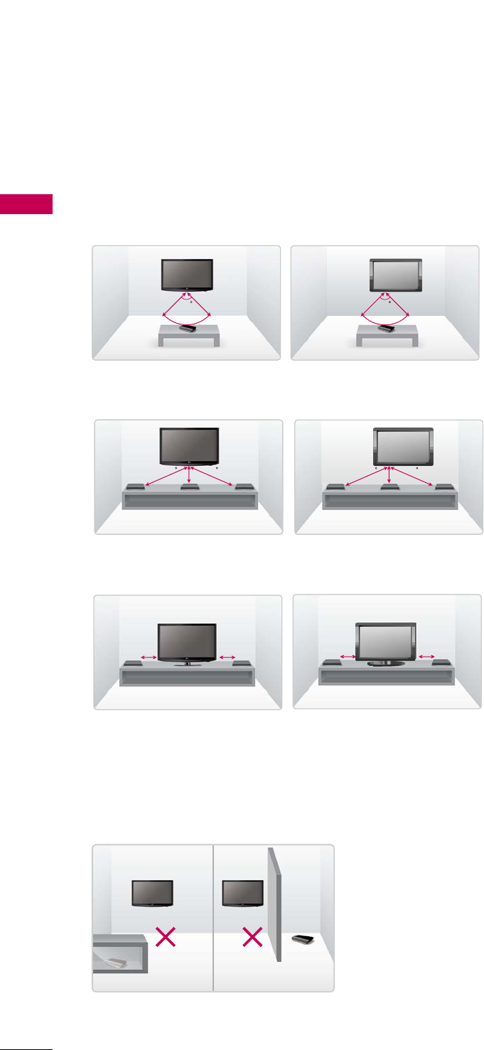
When the Media Box and TV are kept apart
and facing each other
■
Image shown may differ from your TV.
■
This is a recommended installation type for good wireless connection.
Have the RF Receiver/Transmitter of the Media
Box and TV face each other. Keep the distance
between them to within 32.8 feet (10 m) and
maintain the face angle of the TV within 100
degrees.
10m (32.8 feet) 10m
100
10m (32.8 feet) 10m
100
1.7m 1.7m1.7m (5.5 feet)
60 60
1.7m 1.7m1.7m (5.5 feet)
60 60
2m (6.5 feet) 2m
2m (6.5 feet) 2m
When installing the Media Box and TV on the
same wall
Have the Media Box and TV face the front.
Keep the distance between them within 5.5
feet (1.7) m and maintain the face angle of the
TV within 60 degrees.
When installing the Media Box and TV side by
side
Have the Media Box and TV face the front.
Keep the distance between them within 6.5
feet (2 m).
Precaution for installation environment
Do not place any obstacle around the RF Receiver/RF Transmitter.
If you install the Media Box inside a metal cabinet, connection
may fail.
If there are two wireless TV or Media Boxes within LOS (Line Of
Sight) 32.8 feet (10 m), they may interfere with each other and
wireless connection may fail.
Metal cabinet Obstacle
PREPARATION
17
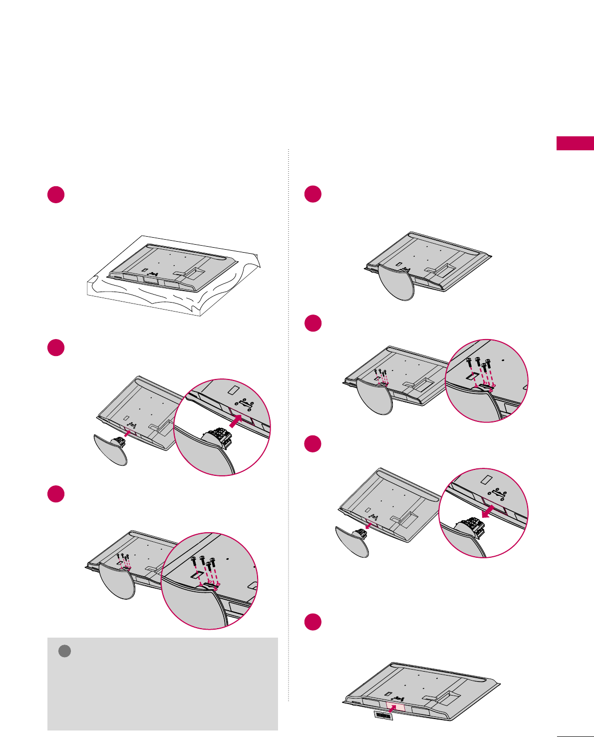
STAND INSTRUCTIONS
(For 47/55LH85)
■
Image shown may differ from your TV.
Carefully place the TV screen side down on a
cushioned surface to protect the screen from
damage.
Assemble the TV as shown.
Fix the 4 screws securely using the holes in the
back of the TV.
1
2
3
INSTALLATION (
For 47LH85)
GWhen assembling the desk type stand, make sure
the screws are fully tightened (If not tightened
fully, the TV can tilt forward after the product
installation). Do not over tighten.
NOTE
!
DETACHMENT
Carefully place the TV screen side down on a
cushioned surface to protect the screen from
damage.
1
Remove the screws from the TV.
2
Detach the stand from TV.
3
PROTECTION COVER
After removing the protection paper from the
PROTECTION COVER, adhere it to the TV
as shown.
4
PREPARATION
18
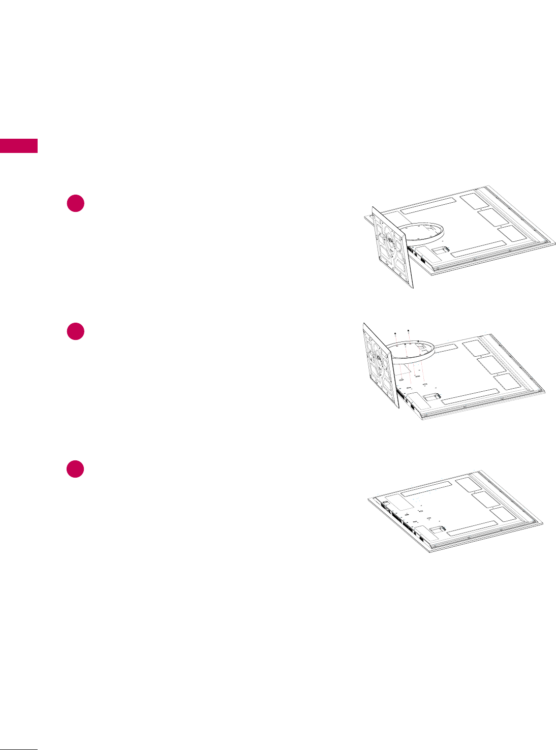
STAND INSTRUCTIONS
(For 55LHX)
PREPARATION
DETACHMENT
Carefully place the TV screen side down on a
cushioned surface to protect the screen from
damage.
1
Remove the screws from the TV.
2
Detach the stand from TV.
3
PREPARATION
19
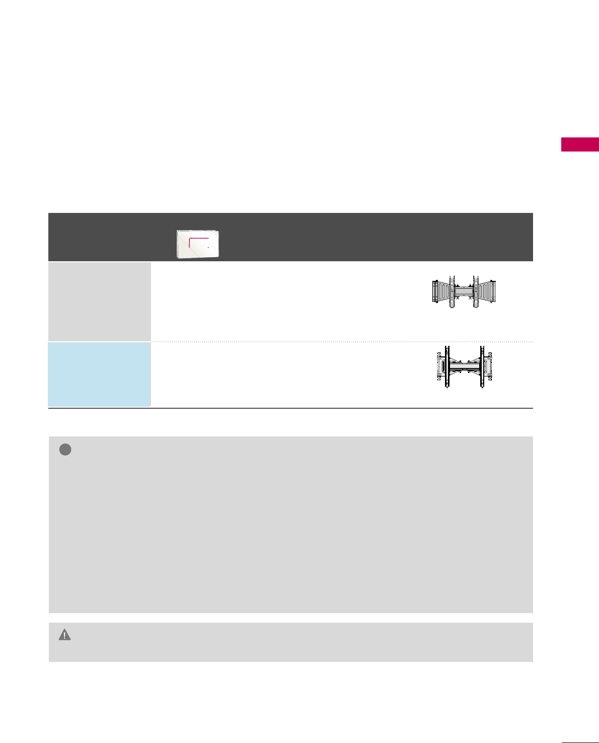
VESA WALL MOUNTING
Install your wall mount on a solid wall perpendicular to the floor. When attaching to other building materials, please
contact your nearest installer.
If installed on a ceiling or slanted wall, it may fall and result in severe personal injury.
We recommend that you use an LG brand wall mount when mounting the TV to a wall.
LG recommends that wall mounting be performed by a qualified professional installer.
GDo not install your wall mount kit while your TV is turned on. It may result in personal
injury due to electric shock.
CAUTION
GScrew length needed depends on the wall mount
used. For further information, refer to the instruc-
tions included with the mount.
GStandard dimensions for wall mount kits are shown
in the table.
GWhen purchasing our wall mount kit, a detailed
installation manual and all parts necessary for
assembly are provided.
GDo not use screws longer then the standard dimen-
sion, as they may cause damage to the inside to
the TV.
GFor wall mounts that do not comply with the VESA
standard screw specifications, the length of the
screws may differ depending on their specifica-
tions.
GDo not use screws that do not comply with the
VESA standard screw specifications.
Do not use fasten the screws too strongly, this may
damage the TV or cause the TV to a fall, leading to
personal injury. LG is not liable for these kinds of
accidents.
GLG is not liable for TV damage or personal injury
when a non-VESA or non specified wall mount is
used or the consumer fails to follow the TV installa-
tion instructions.
NOTE
!
Model
VESA (A *B)
Standard Screw Quantity Wall Mounting Bracket
(sold separately)
55LH85,
55LHX
47LH85 200 * 200 M6 4
400 * 400 M6 4
AW-55LH40M
AA
BB
AW-47LG30M
PREPARATION
20
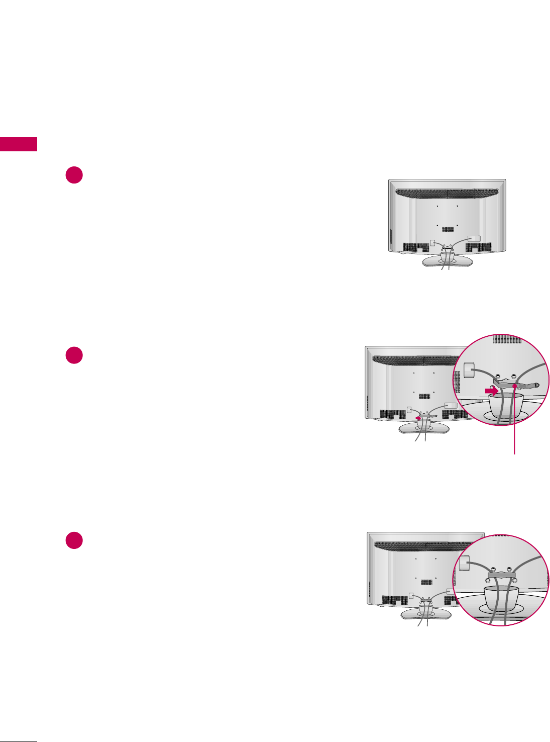
CABLE MANAGEMENT
PREPARATION
■
Image shown may differ from your TV.
CABLE MANAGEMENT CLIP
Connect the cables as necessary.
To connect additional equipment, see the
EXTERNAL EQUIPMENT SETUP section.
1
Open the CABLE MANAGEMENT CLIP as
shown.
2
Put the cables inside the CABLE MANAGE-
MENT CLIP and snap it closed.
3
For 47/55LH85