LG Electronics USA 62DC1DUC 62" DLP PROJECTION TV User Manual User s Manual H ok
LG Electronics USA 62" DLP PROJECTION TV User s Manual H ok
USERS MANUAL

EUT Type: 62” DLP projection TV/Monitor
FCC ID: BEJ62DC1DUC
Test Report No.: GETEC-E3-06-005
FCC Class B Certification
APPENDIX H
: USER’S MANUAL

© Copyright 2005, LG Electronics USA, Inc.
Installation and Operating Guide |Warranty
Model Numbers |Z56DC1D/Z62DC1D |DLP PROJECTION
2 DLP Projection TV
WARNING/CAUTION:
TO REDUCE THE RISK OF ELECTRIC SHOCK DO NOT REMOVE COVER (OR BACK). NO USER
SERVICEABLE PARTS INSIDE. REFER TO QUALIFIED SERVICE PERSONNEL.
The lightning flash with arrowhead symbol, within an equilateral triangle, is intended to alert the user to
the presence of uninsulated “dangerous voltage” within the product’s enclosure that may be of suffi-
cient magnitude to constitute a risk of electric shock to persons.
The exclamation point within an equilateral triangle is intended to alert the user to the presence of
important operating and maintenance (servicing) instructions in the literature accompanying the appli-
ance.
WARNING/CAUTION:
TO PREVENT FIRE OR SHOCK HAZARDS, DO NOT EXPOSE THIS PRODUCT TO RAIN OR MOISTURE.
POWER CORD POLARIZATION:
CAUTION: TO PREVENT ELECTRIC SHOCK, MATCH WIDE BLADE OF PLUG TO WIDE SLOT, FULLY
INSERT.
ATTENTION: POUR ÉVITER LES CHOCS ÉLECTRIQUES, INTRODUIRE LA LAME LA PLUS LARGE
DE LA FICHE DANS LA BORNE CORRESPONDANTE DE LA PRISE ET POUSSER JUSQU’AU FOND.
NOTE TO CABLE/TV INSTALLER:
This reminder is provided to call the CATV system installer’s attention to Article 820-40 of the National
Electric Code (U.S.A.). The code provides guidelines for proper grounding and, in particular, specifies that
the cable ground shall be connected to the grounding system of the building, as close to the point of the
cable entry as practical.
REGULATORY INFORMATION:
This equipment has been tested and found to comply with the limits for a Class B digital device, pursuant to Part
15 of the FCC Rules. These limits are designed to provide reasonable protection against harmful interference in
a residential installation. This equipment generates, uses and can radiate radio frequency energy and, if not
installed and used in accordance with the instructions, may cause harmful interference to radio communications.
However, there is no guarantee that interference will not occur in a particular installation. If this equipment does
cause harmful interference to radio or television reception, which can be determined by turning the equipment off
and on, the user is encouraged to try to correct the interference by one or more of the following measures:
- Reorient or relocate the receiving antenna.
- Increase the separation between the equipment and receiver.
- Connect the equipment into an outlet on a circuit different from that to which the receiver is connected.
- Consult the dealer or an experienced radio/TV technician for help.
Any changes or modifications not expressly approved by the party responsible for compliance could void the
user’s authority to operate the equipment.
CAUTION:
Do not attempt to modify this product in any way without written authorization from LG Electronics. Unauthorized mod-
ification could void the user’s authority to operate this product.
COMPLIANCE:
The responsible party for this product’s compliance is:
Zenith Electronics Corporation
1-201-816-2000
Marked and Distributed in the United States by LG Electronics U.S.A., Inc.
1000 Sylvan Avenue, Englewood Cliffs, NJ 07632
http://www.zenith.com
WARNING
RISK OF ELECTRIC SHOCK
DO NOT OPEN
/CAUTION
W
Warning/Caution
arning/Caution
Warning/Caution

Owner’s Manual 3
Safety Instructions
IMPORTANT SAFETY INSTRUCTIONS
Important safety instructions shall be provided with each apparatus. This information shall be given in a separate booklet or
sheet, or be located before any operating instructions in an instruction for installation for use and supplied with the appara-
tus. This information shall be given in a language acceptable to the country where the apparatus is intended to be used. The
important safety instructions shall be entitled “Important Safety Instructions”. The following safety instructions shall be includ-
ed where applicable, and, when used, shall be verbatim as follows. Additional safety information may be included by adding
statements after the end of the following safety instruction list. At the manufacturer’s option, a picture or drawing that illus-
trates the intent of a specific safety instruction may be placed immediately adjacent to that safety instruction :
1. Read these instructions.
2. Keep these instructions.
3. Heed all warnings.
4. Follow all instructions.
5. Do not use this apparatus near water.
6. Clean only with dry cloth.
7. Do not block any ventilation openings. Install in accordance with the manufacturer’s instructions.
8. Do not install near any heat sources such as radiators, heat registers, stoves, or other apparatus (including ampli-
fiers)that produce heat.
9. Do not defeat the safety purpose of the polarized or grounding-type plug. A polarized plug has two blades with
one wider than the other. A grounding type plug has two blades and a third grounding prong, The wide blade or the
third prong are provided for your safety. If the provided plug does not fit into your outlet, consult an electrician for
replacement of the obsolete outlet.
10. Protect the power cord from being walked on or pinched particularly at plugs, convenience receptacles, and the
point where they exit from the apparatus.
11. Only use attachments/accessories specified by the manufacturer.
12. Use only with the cart, stand, tripod, bracket, or table specified by the manufacturer, or sold with the apparatus.
When a cart is used, use caution when moving the cart/apparatus combination to avoid injury from tip-over.
Safety Instructions
Safety Instructions
PORTABLE CART WARNING

4 DLP Projection TV
Safety Instructions
13. Unplug this apparatus during lightning storms or when unused for long periods of time.
14. Refer all servicing to qualified service personnel. Servicing is required when the apparatus has been damaged
in any way, such as power-supply cord or plug is damaged, liquid has been spilled or objects have fallen into
the apparatus, the apparatus has exposed to rain or moisture, does not operate normally, or has been dropped.
15. CAUTION concerning the Power Cord :
Most appliances recommend they be placed upon a dedicated circuit; that
is, a single outlet circuit which powers only that appliance and has no
additional outlets or branch circuits. Check the specification page of
this owner's manual to be certain.
Do not overload wall outlets. Overloaded wall outlets, loose or damaged
wall outlets, extension cords, frayed power cords, or damaged or
cracked wire insulation are dangerous. Any of these conditions could
result in electric shock or fire. Periodically examine the cord of your
appliance, and if its appearance indicates damage or deterioration,
unplug it, discontinue use of the appliance, and have the cord replaced
with an exact replacement part by an authorized servicer.
Protect the power cord from physical or mechanical abuse, such as being
twisted, kinked, pinched, closed in a door, or walked upon. Pay
particular attention to plugs, wall outlets, and the point where the
cord exits the appliance.
16. Outdoor Use Marking :
WARNING - To Reduce The Risk Of Fire Or Electric Shock, Do Not Expose This Appliance To Rain Or Moisture.
17. Wet Location :
Apparatus shall not be exposed to dripping or splashing and no objects filled with liquids, such as vases, shall
be placed on the apparatus.
6 DLP Projection TV
Introduction
Introduction
Introduction
INPUT VOL CH
ENTER
MENU
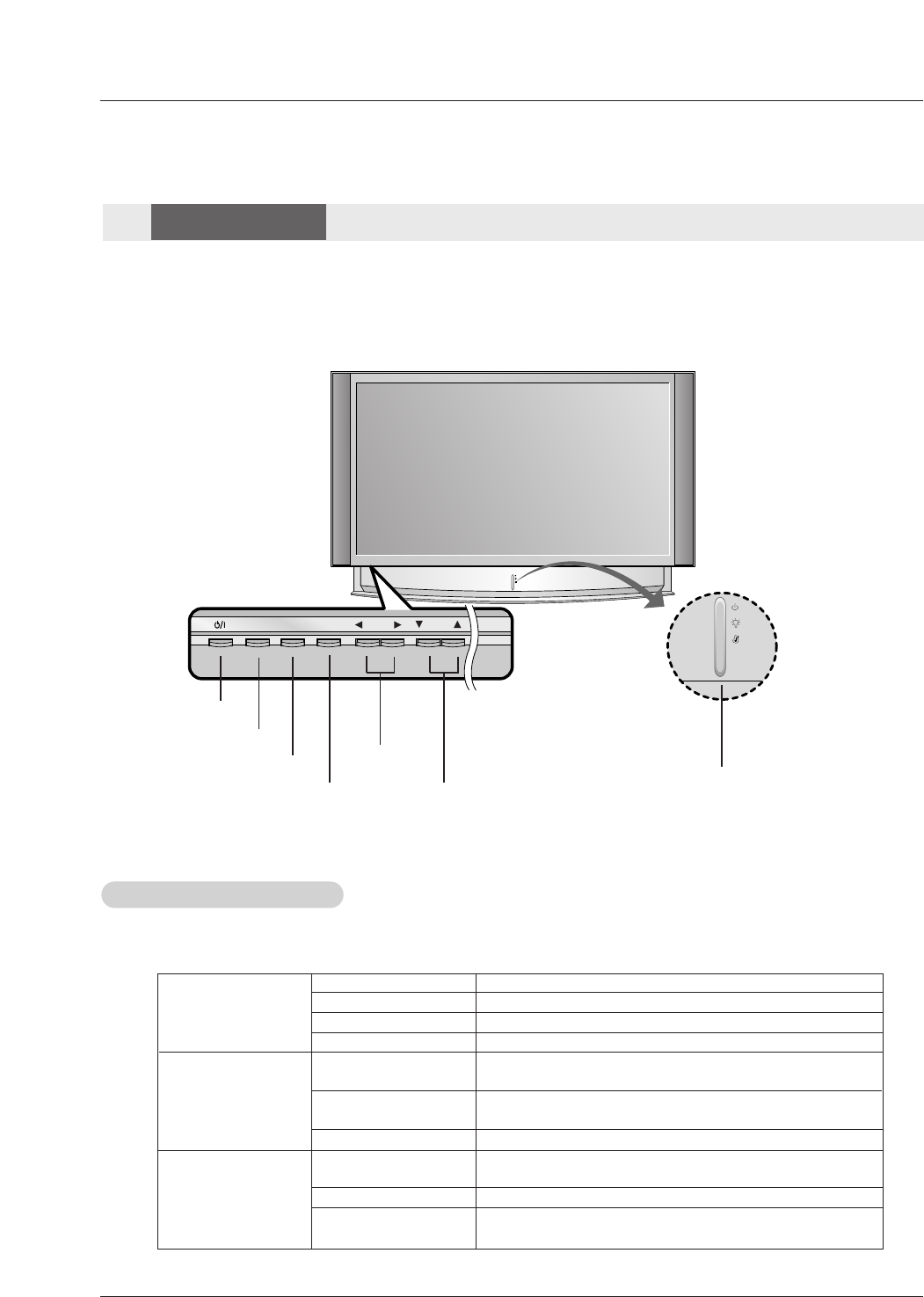
- Lamp indicator, operation indicator, and temperature indicator located below the front panel controls, reveal the
operating status of the DLP projection TV.
Function Status Indicators
Function Status Indicators
Controls
Controls
Front Panel Controls
Front Panel Controls
Off Power cord is not connected.
Red Power Cord is connected, TV is in standby mode.
Green TV turns on.
Orange (blinking) Preparing operation in standby mode.
Orange Projection lamp is reaching the end of its life and needs to
be replaced with a new lamp. Contact your service center.
Red (blinking) There is a problem with the lamp or around it. Contact an
authorized service center.
Green (blinking) The lamp cover is not closed.
Orange The projection TV is overheating. Check for blocked vents on
the projection TV.
Red The projection TV shut down due to overheating.
Red (blinking) The projection TV shut down, check the cooling fan. Contact
your service center.
Operation Indicator
Lamp Indicator
Temperature Indicator
- This is a simplified representation of a front panel.
- Image shown may be somewhat different from your TV.
POWER Button
MENU Button
ENTER Button
VOLUME (FF,GG)
Buttons
CHANNEL (EE, DD)
Buttons
Operation Indicator/
Lamp Indicator/
Temperature Indicator
INPUT Button
Owner’s Manual 7
Introduction
RGB
(PC/DTV)
S-VIDEO
PR
PB
Y
MONO
RGB IN
COMPONENT IN
21
(L)
(R)
AUDIO
RGBDVI
(L)
(R)
AUDIO
VIDEO
(L)
(R)
AV IN 1 AV OUT
DIGITAL AUDIO
OPTICAL OUTPUT
ANTENNA
SERVICE ONLY
VIDEO
AUDIO
HDMI
/DVI IN
RGB
(PC/DTV)
S-VIDEO
PR
PB
Y
MONO
RGB IN
COMPONENT IN
21
(L)
(R)
AUDIO
RGBDVI
(L)
(R)
AUDIO
VIDEO
(L)
(R)
AV IN 1 AV OUT
DIGITAL AUDIO
OPTICAL OUTPUT
ANTENNA
SERVICE ONLY
VIDEO
AUDIO
HDMI
/DVI IN
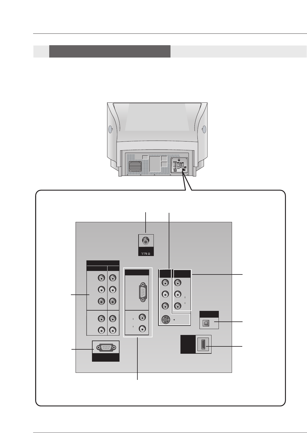
Back Connection Panel
Back Connection Panel
Connection Options
Connection Options
ANTENNA IN
COMPONENT
IN 1/2
SERVICE
ONLY
HDMI/DVI
IN
DIGITAL AUDIO
OPTICAL OUT
AV IN 1
AV OUT
RGB IN
RGB(PC/DTV)
RGB/DVI
8 DLP Projection TV
Introduction
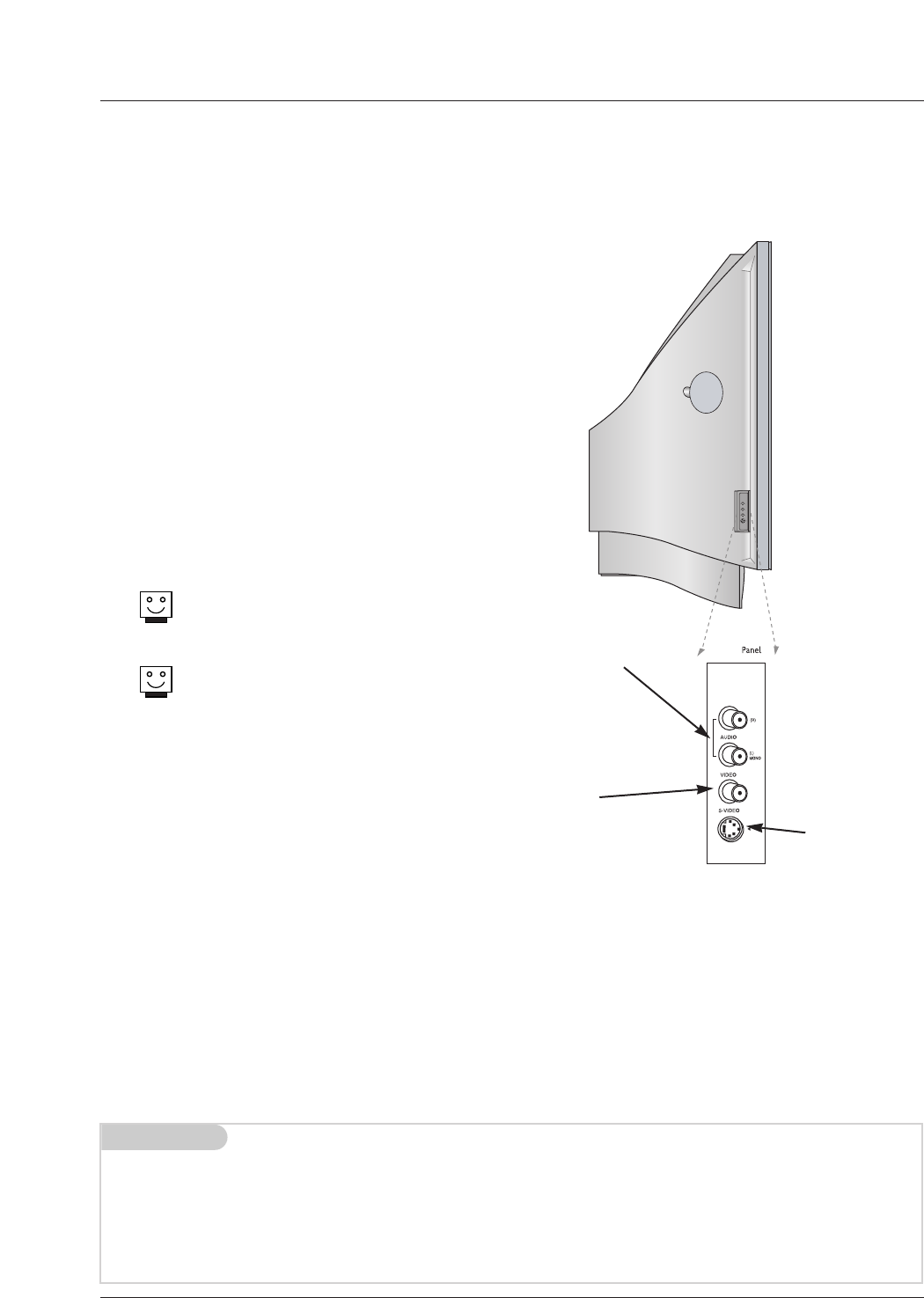
LEFT/RIGHT
AUDIO
Used for stereo
sound from vari-
ous types of
equipment.
S-VIDEO
A connection
available on
some very high-
end equipment
that provides bet-
ter picture quality
than video input.
VIDEO
Connects the
video signals
from any piece of
equipment.
AV IN 2 AV IN 2
AV IN 2
/
There are four jacks on the left side on your projection TV
that make connecting Audio/Video devices like video
games and camcorders very simple.
The jacks are like those found on the back jack connection
panel. This means that most equipment that connects to
those types of jacks on the rear jackpack, may be connect-
ed to the front connection panel.
To use the side jacks as the signal source, select them
using Main Input menu as described on page 23. They will
be named “Front Video” in the Main Input menu.
If you input both Front Video and
S-Video, only the S-Video will
work.
If you’re connecting a video game
device, make sure to change the
picture settings with the EZ
Picture option in the Video menu
(see page 24).
Mini glossary
A/V CABLESAudio/Video cables. Three cable connector—Right audio (red), Left audio (white), and Video (yellow). A/V cables are
used for stereo playback of videocassettes and for higher quality picture and sound from other A/V devices.
A/V DEVICE Any device that produces video or sound (VCR, DVD, cable box, or television).
Front Connection Panel
Front Connection Panel
Owner’s Manual 11
Installation
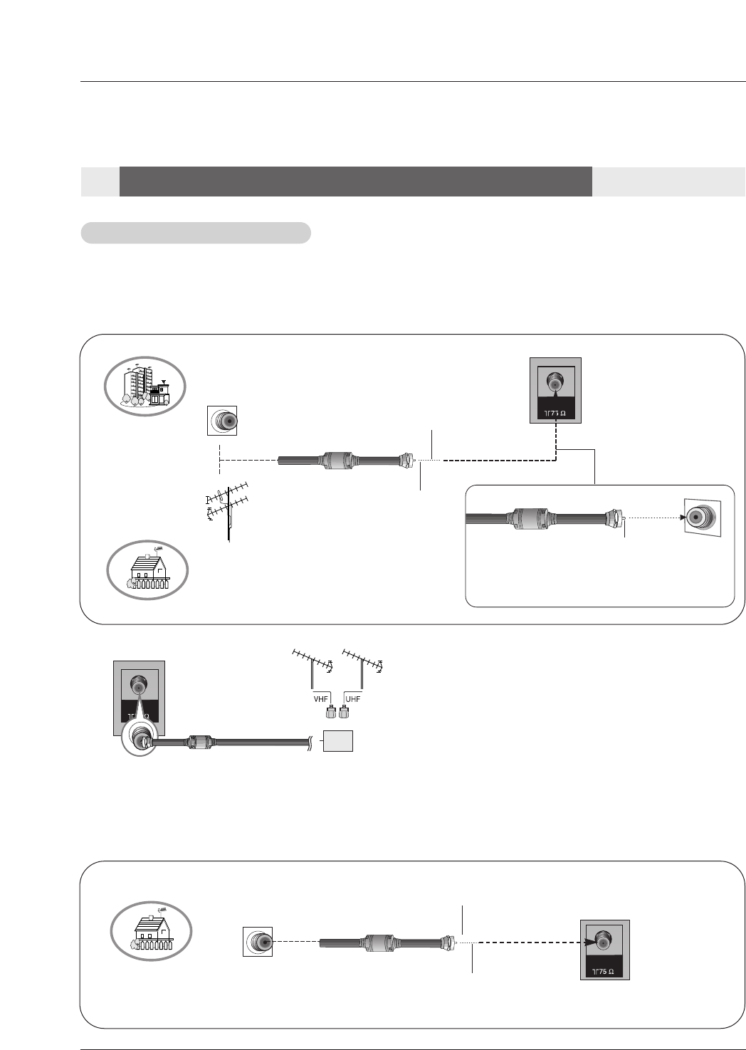
- Wall Antenna Socket or Outdoor Antenna without a Cable Box Connections
- For optimum picture quality, adjust antenna direction if needed.
Antenna or Cable Connection
Antenna or Cable Connection
1. Analog and Digital TV signals provided on one antenna
2. Analog and DTV signals provided on two separate antennas
ANTENNA
Multi-family Dwellings/Apartments
(Connect to wall antenna socket)
Single-family Dwellings /Houses
(Connect to wall jack for outdoor antenna)
Outdoor
Antenna
Wall Antenna
Socket
VHF Antenna
UHF Antenna
RF Coaxial Wire (75 ohm)
Copper Wire
Turn clockwise to tighten.
Copper Wire
Be careful not to bend the Copper Wire when
connecting the antenna.
Copper Wire
Cable TV Wall
Jack RF Coaxial Wire (75 ohm)
ANTENNA
Installation
Installation
External Equipment Connections
External Equipment Connections
Turn clockwise to tighten.
Note: The TV will let you know when the TV(analog antenna), DTV(digital antenna), CATV(analog cable) and CADTV(digital
cable) channel scans are complete.
•To improve the picture quality in a poor signal area,
please purchase a signal amplifier and install properly.
•If the antenna needs to be split for two TV’s, install a “2-
Way Signal Splitter” in the connections.
•If the antenna is not installed properly, contact your deal-
er for assistance.
ANTENNA
Signal
Amplifier
14 DLP Projection TV
PC Setup
PC Setup
- This TV provides Plug and Play capability, meaning that the PC adjusts automatically to the TV's settings.
- The TV perceives 640x480, 60Hz as DTV 480p based on the PC graphic card, change the screen scanning rate for the graphic
card accordingly.
Resolution
800x600
Horizontal
Frequency(KHz)
70.09
59.94
72.80
75.00
48.363
56.476
60.023
Vertical
Frequency(Hz)
1024x768
Monitor Display Specifications (RGB-PC or HDMI1/DVI Mode)
35.156
37.879
48.077
46.875
56.25
60.31
72.18
75.00
60.00
70.06
75.02
Installation
The TV has a special signal output capability which allows you to
hook up a second TV or monitor.
Connect the second TV or monitor to the TV’s MONITOR OUTPUT.
See the Operating Manual of the second TV or monitor for further
details regarding that device’s input settings.
Note
• Component, RGB-PC/RGB-DTV, HDMI1/DVI,HDMI2, DTV input
sources cannot be used for Monitor out.
Monitor Out Setup
Monitor Out Setup
S-VIDEO IN
(R) AUDIO (L) VIDEO
S-VIDEO
MONO
RGB INPUT
RGB/DVI INPUT
(L)
(R)
AUDIO
(L)
(R)
AUDIO
MONITOR
OUT INPUT2 INPUT1
VARIABLE
AUDIO OUT
PC/DTV
(XGA/
480p/
720p/
1080i)
31.468
31.469
37.861
37.500
640x350
640x480
RGB-PC
Mode Only
Owner’s Manual 15
Installation
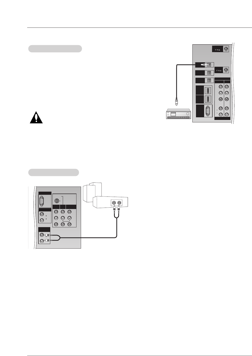
Send the TV’s audio to external audio equipment (stereo system) via
the Digital Audio Output (Optical) port.
How to connect
1. Connect one end of an optical cable to the TV Digital Audio
(Optical) Output port.
2. Connect the other end of the optical cable to the digital audio (opti-
cal) input on the audio equipment.
3. Set the “ TV Speaker option - Off”in the AUDIO menu. Refer to
page 26.
See the external audio equipment instruction manual for operation.
Caution: Do not look into the optical output port. Looking
at the light may damage your vision.
Digital
Digital Audio Output
Audio Output
C
A
B
L
E
C
A
R
D
DVI
HDMI
PR
PB
Y
COMPONENT
INPUT2 INPUT1
DTV/DVD INPUT
(L)
(R)
AUDIO
DIGITAL AUDIO
OPTICAL INPUT
(COMPONENT2)
DIGITAL AUDIO
OPTICAL INPUT
(DVI)
DIGITAL AUDIO
OPTICAL OUTPUT
ANTENNA
H
D
M
I
1
UPGRADE
PORT
CABLE
/
D
V
I
H
D
M
I
2
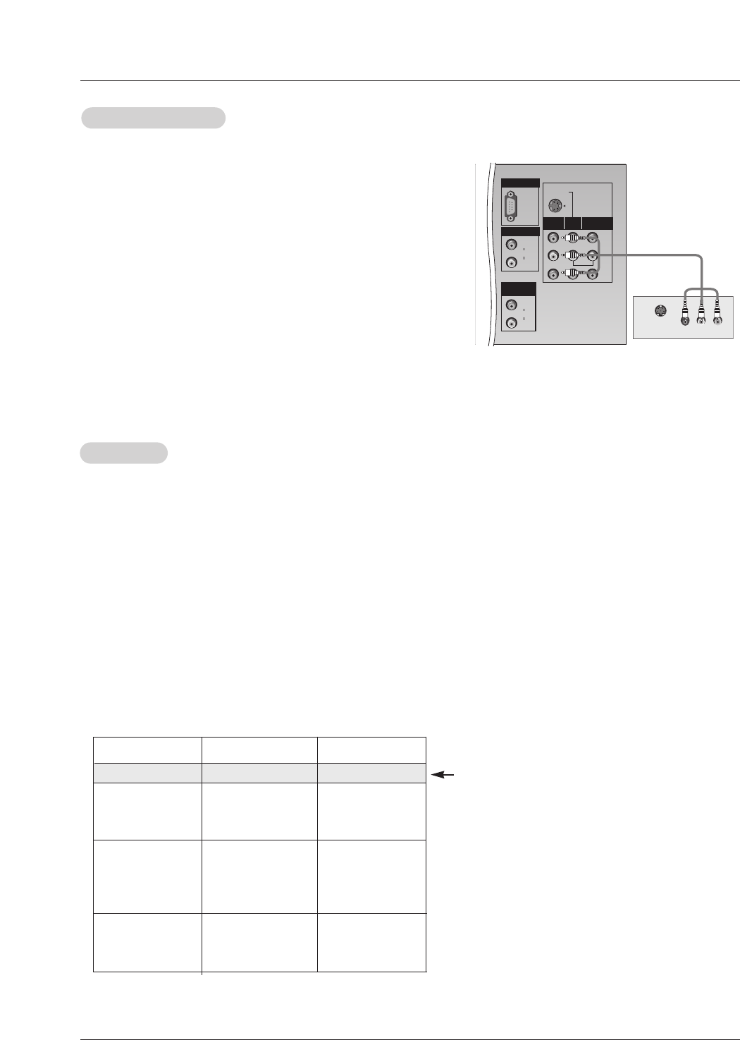
Hook up Variable Audio Output, L-Audio-R to Amplifier system for
Left/Right front speaker sound.
How to connect
1. Locate the Variable Audio Out jacks on the back of your TV and the
Input jacks on the back of your stereo's amplifier.
2. Connect the two jacks, making sure that the right and left channels
are connected correctly.
3. Set up your speakers through your analog stereo amplifier, accord-
ing to the instructions provided with the amplifier.
External Stereo
External Stereo
S-VIDEO
MONO
RGB INPUT
RGB/DVI INPUT
(L)
(R)
AUDIO
(L)
(R)
AUDIO
MONITOR
OUT INPUT2 INPUT1
VARIABLE
AUDIO OUT
PC/DTV
(XGA/
480p/
720p/
1080i)

16 DLP Projection TV
Installation
- HDMITM, the HDMI logo and High-Definition Multimedia Interface is a trademark or registered trademark of HDMI Licensing.
- This TV can receive the High-Definition Multimedia Interface(HDMI) or the Digital Visual Interface(DVI).
- This TV supports HDCP(High-bandwidth Digital Contents Protection) Protocol for 720x480p, 1280x720p, and 1920x1080i resolu-
tions.
- When you connect this TV with a source device(DVD player, Set Top Box or PC) supporting Auto HDMI/DVI function, the output
resolution of the source device will be automatically set to 1280x720p.
- If the source device does not support Auto HDMI/DVI, you need to set the output resolution appropriately.
To get the best picture quality, adjust the DVD Player or Set Top Box's output resolution to 1280x720p, and the PC graphics card's
output resolution to 1024x768, 60Hz.
- If the source device has an HDMI output, no other audio connection is necessary because HDMI-to-HDMI connection includes
both video and audio.
- If the source device has a DVI output and no HDMI output, a separated audio connection is necessary.
<When the source device(DVD player or Set Top Box) supports HDMI>
How To Connect
1. Connect the source device to HDMI1/DVI or HDMI2 port of this TV with an HDMI cable(not supplied with this product).
2. No separated audio connection is necessary.
How To Use
- If the source device supports Auto HDMI function, the output resolution of the source device will be automatically set to 1280x720p.
- If the source device does not support Auto HDMI, you need to set the output resolution appropriately.
To get the best picture quality, adjust the output resolution of the source device to 1280x720p.
- Select HDMI1/DVI or HDMI2 input source in main input option on the SETUP menu.(Refer to P.23)
TV/VIDEO button is also available for this purpose.
<When the source device(DVD player or Set Top Box) supports DVI>
How To Connect
1. Connect the source device to HDMI1/DVI port of this TV with a HDMI-to-DVI cable(not supplied with this product).
Do not use HDMI2 port for DVI connection if you want to connect audio.
2. A separated audio connection is necessary.
3. If the source device has a fiber optic digital audio output, connect the audio output to DIGITAL AUDIO(OPTICAL) port for DVI
INPUT.
4. Connect the PC's audio output to AUDIO INPUT port located on the right side of RGB INPUT port.
How To Use
- If the source device supports Auto DVI function, the output resolution of the source device will be automatically set to 1280x720p.
- If the source device does not support Auto DVI, you need to set the output resolution appropriately.
To get the best picture quality, adjust the output resolution of the source device to 1280x720p.
- Select HDMI1/DVI input source in main input option on the SETUP menu.(Refer to P.23)
TV/VIDEO button is also available for this purpose.
HDMI
HDMI
Owner’s Manual 17
Installation
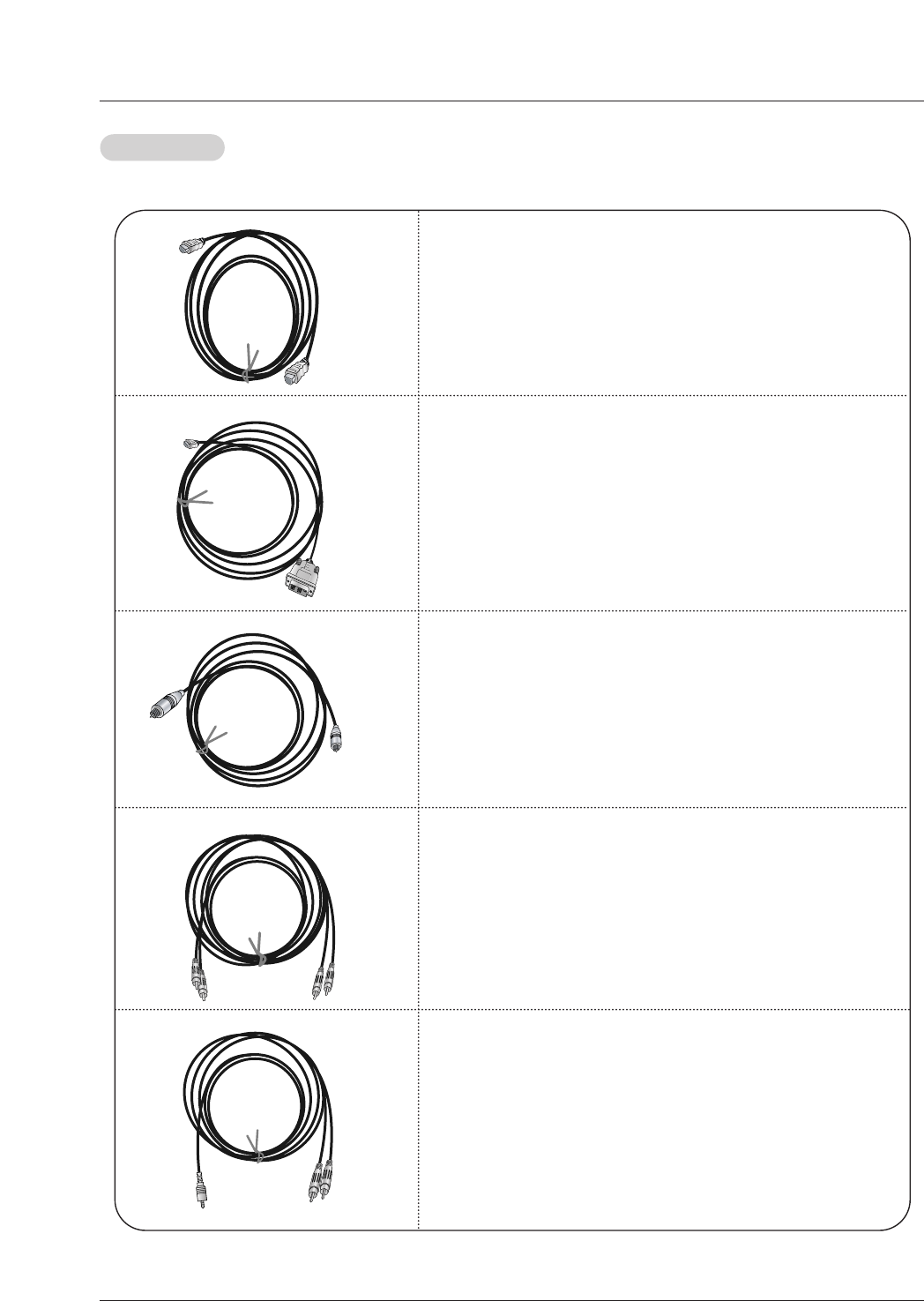
Cable sample
HDMI Cable
(not supplied with the product)
HDMI to DVI Cable
(not supplied with the product)
Fiber Optic Digital Audio Cable
(not supplied with the product)
Analog Audio Cable(RCA type)
(not supplied with the product)
Analog Audio Cable(Stereo to RCA type)
(not supplied with the product)
Reference
Reference

18 DLP Projection TV
How to use
1. Connect the HDMI1/DVI Source Devices(DVD Player or Set Top Box or PC) and the TV SET.
2. Turn on the display by pressing the POWER button on the TV SET and HDMI1/DVI Source Devices remote control.
3. Select HDMI1/DVI Input source in Main Input option on the SETUP menu.(Refer to P.23)
4. Check the image on your TV SET. There may be noise associated with the resolution, vertical pattern, contrast or brightness in
HDMI1/DVI Source Devices. If noise is present, change the HDMI1/DVI Source Devices to another resolution, change the
refresh rate or adjust the brightness and contrast on the menu until the picture is clear. If the refresh rate of the PC graphics
card can not changed, change the PC graphics card or consult the manufacturer of the PC graphics card.
Notes:
- Depending on the graphics card, DOS mode may not work if a HDMI to DVI Cable is in use.
- When Source Devices connected with HDMI1/DVI Input, output TV SET Resolution(480p, 720p, 1080i) and TV SET Display fit
EIA/CEA-861-B Specification to Screen. If not, refer to the Manual of HDMI1/DVI Source Devices or contact your service cen-
ter.
- In case HDMI1/DVI Source Devices is not connected Cable or poor cable connection, "NO SIGNAL" OSD display in HDMI1/DVI
Input. In case that Video Resolution is not supported TV SET output in HDMI1/DVI Source Devices, "INVALID FORMAT" OSD
display. Refer to the Manual of HDMI1/DVI Source Devices or contact your service center.
In DTV Mode, the Supported TV Set Resolution Specification
- 1920 x 1080 I @ 59.94Hz / 60Hz, 16:9
- 1280 x 720 P @ 59.94Hz / 60Hz, 16:9(preferred format)
- 720 x 480 P @ 59.94Hz / 60Hz, 16:9
- 720 x 480 P @ 59.94Hz / 60Hz, 4:3
In PC Mode, the Supported PC Resolution Specification
- 640 x 480 @ 60Hz
- 640 x 480 @ 72Hz
- 640 x 480 @ 75Hz
- 800 x 600 @ 56Hz
- 800 x 600 @ 60Hz
- 800 x 600 @ 72Hz
- 800 x 600 @ 75Hz
- 1024 x 768 @ 60Hz(preferred format)
- 1024 x 768 @ 70Hz
- 1024 x 768 @ 75Hz
28 DLP Projection TV
Operation
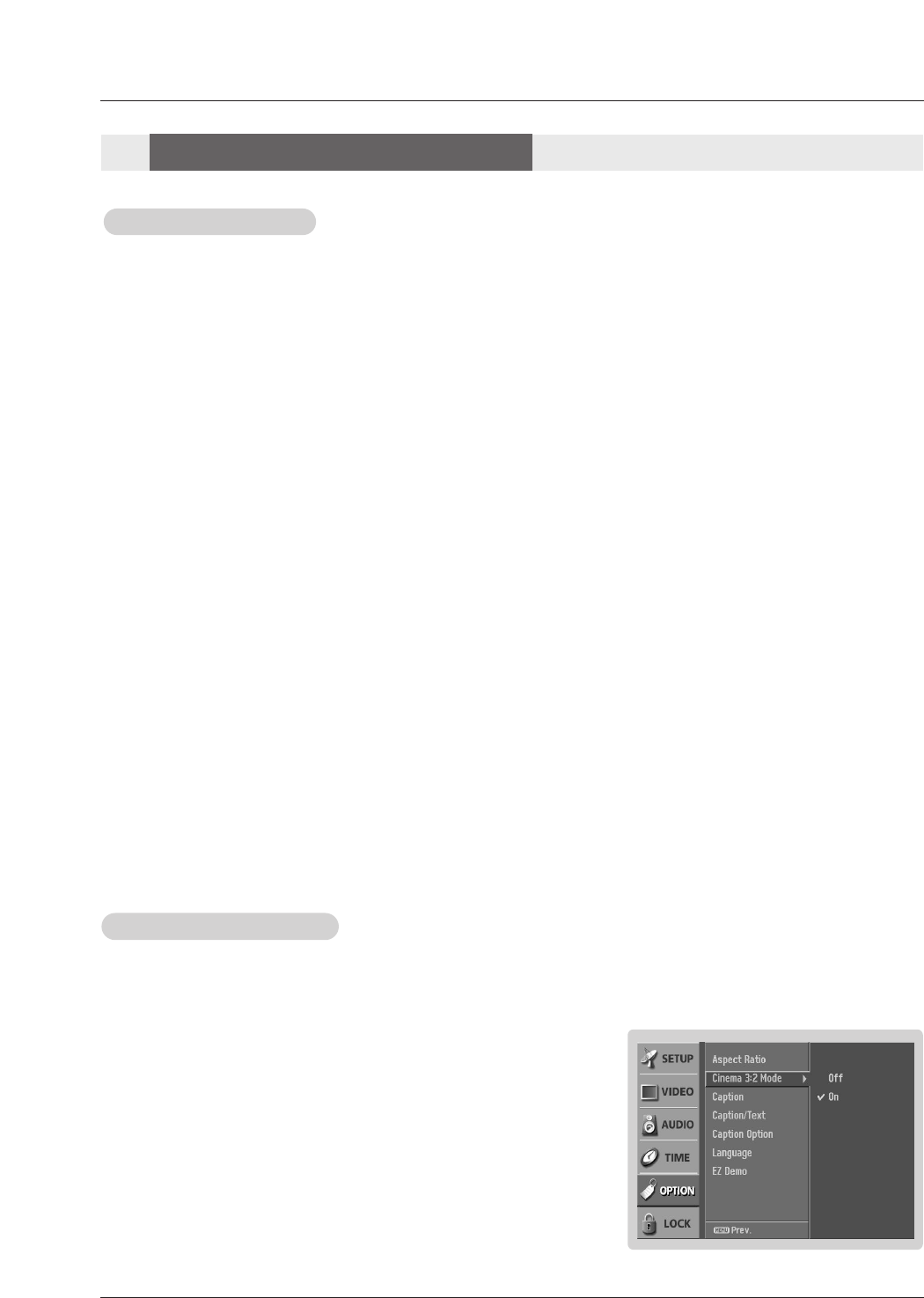
Cinema 3:2 Mode Setup
Cinema 3:2 Mode Setup
- Most movies are 24 frames/sec, but TV signal is 30 frames/sec.
This option lets the TV do 3:2 pull-down operation for you to watch
movies with the best motion appearance.
1. Press the MENU button and then use DD / EEbutton to select the OPTION menu.
2. Press the GGbutton and then use DD / EEbutton to select Cinema 3:2 Mode.
3. Press the GGbutton and then use DD / EEbutton to select On or Off.
4. Press EXIT button to return to TV viewing or press MENU button to return to the
previous menu.
Aspect Ratio Control
Aspect Ratio Control
- Lets you choose the way an analog picture with a 4:3 aspect ratio is displayed on your TV with a 16:9 ratio picture format.
When you receive an analog picture with a 4:3 aspect ratio on your 16:9 TV, you need to specify how the picture is to be dis-
played.
- Horizon aspect ratio is not available for Component 1-2 (720p/1080i)/RGB-DTV (720p/1080i)/HDMI1/DVI-DTV(720p/1080i), HDMI2-
DTV(720p/1080i)/ CADTV, DTV(720p/1080i) input source.
- RGB-PC/DVI-PC input source use 4:3 or 16:9 aspect ratio.
• Set By Program
Selects the proper picture proportion to match the source’s image. (4:3 →4:3, 16:9 → 16:9)
• 4:3
Choose 4:3 when you want to view a picture with an original 4:3 aspect ratio, with black bars appearing at both
the left and right sides.
• 16:9
Choose 16:9 when you want to adjust the picture horizontally, in a linear proportion to fill the entire screen.
• Horizon
Choose Horizon when you want to adjust the picture in a non-linear proportion, that is, more enlarged at both
sides, to create a spectacular view.
• Zoom 1
Choose Zoom 1 when you want to view the picture without any alteration. However, the top and bottom portions
of the picture will be cropped.
• Zoom 2
Choose Zoom 2 when you want the picture to be altered, both horizontally extended and vertically cropped. The
picture taking a halfway trade off between alteration and screen coverage.
• Cinema Zoom
Choose Cinema Zoom when you want to enlarge the picture in correct proportion. Note: When enlarging or
reducing the picture, the image may become distorted.
You can adjust the enlarge proportion of Cinema Zoom using DD / EEbutton. The adjustment range is 1~16.
1. Press the RATIO button repeatedly to select the desired picture format.
You can also adjust the Aspect Ratio in the OPTION menu.
Option Menu Options
Option Menu Options
Note: This feature operates only in 480i mode.
Owner’s Manual 29
Operation
Caption
Caption
Digital Broadcasting System Captions
- Choose the language you want the DTV/CADTV Captions to appear in.
- Languages can be chosen for digital sources only if they are included on the
program.
1. Press the MENU button and then use DD / EEbutton to select the OPTION menu.
2. Press the GGbutton and then use DD / EEbutton to select Caption/Text.
3. Press the GGbutton and then use DD / EEbutton to select available caption lan-
guages: English, Spanish, or French.
4. Press EXIT button to return to TV viewing or press MENU button to return to the
previous menu.
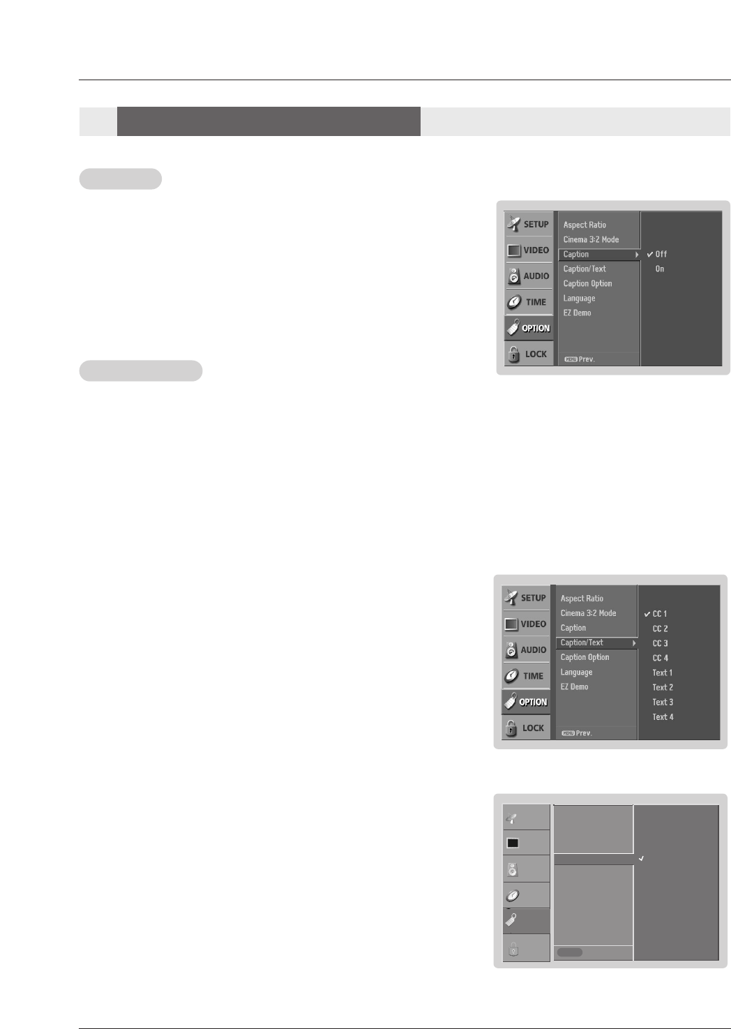
1. Press the MENU button and then use DD / EEbutton to select the OPTION menu.
2. Press the GGbutton and then use DD / EEbutton to select Caption.
3. Press the GGbutton and then use DD / EEbutton to select On or Off.
4. Press EXIT button to return to TV viewing or press MENU button to return to the
previous menu.
Caption/T
Caption/Text
ext
Analog Broadcasting System Captions
- Select a caption mode for displaying captioning information if provided on a program.
- Analog caption displays information at any position on the screen usually the program's dialog.
- Text displays information, usually at the bottom position and is used for a data service, generally not program related.
- Caption/Text, if provided by the broadcaster, would be available for both digital and analog channels on the Antenna/Cable.
- This TV is programmed to remember the caption/text mode it was last set to, when you turn the power off.
1. Press the MENU button and then use DD / EEbutton to select the OPTION menu.
2. Press the GGbutton and then use DD / EEbutton to select Caption/Text.
3. Press the GGbutton and then use DD / EEbutton to select caption: CC1, CC2, CC3,
CC4, Text1, Text2, Text3, or Text4.
• CAPTION
The term for the words that scroll across the bottom of the TV screen; usually
the audio portion of the program provided for the hearing impaired.
• TEXT
The term for the words that appear in a large black frame and almost cover
the entire screen; usually messages provided by the broadcaster.
4. Press EXIT button to return to TV viewing or press MENU button to return to the
previous menu.
1. Use the CC button repeatedly to select Caption CC1, CC2, CC3, CC4, Text1, Text2, Text3, or Text4.
2. Press EXIT button to save and return to TV viewing.
• You can also use the OPTION menu to select Caption/Text.
Option Menu Options
Option Menu Options
Prev.
MENU
English
Spanish
French
Aspect Ratio
Cinema 3:2 Mode
Caption
Caption / Text GG
Caption Option
Language
EZ Demo
SETUP
VIDEO
AUDIO
TIME
OPTION
LOCK
30 DLP Projection TV
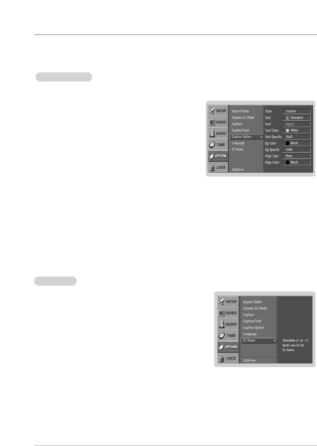
Caption Option
Caption Option
- Customize the DTV/CADTV captions that appear on your screen.
1. Press the MENU button and then use DD / EEbutton to select the OPTION
menu.
2. Press the GGbutton and then use DD / EEbutton to select Caption Option.
3. Press the GGbutton and then use FF / GGbutton to select Custom.
4. Use DD / EEbutton to customize the Style, Font, etc., to your preference. A pre-
view icon is provided at the bottom of the screen, use it to see the caption lan-
guage.
• Size: Set the size the words will appear in.
• Font: Select a typeface for the words.
• Text Color: Choose a color for the text.
• Text Opacity: Specify the opacity for the text color.
• Bg (Background) Color: Select a background color.
• Bg (Background) Opacity: Select the opacity for the background color.
• Edge Type: Select an edge type.
• Edge Color: Select a color for the edges.
5. Press EXIT button to return to TV viewing or press MENU button to return
to the previous menu.
EZ Demo
EZ Demo
Shows you how to navigate the TV's on-screen menus.
EZ Demo Use to scan the features and menu options available on your TV.
1. Press the MENU button and then use DD / EEbutton to select the OPTION
menu.
2. Press the GGbutton and then use DD / EEbutton to select EZ Demo, then use the GG
button to start EZ Demo.
3. Press EXIT button to stop EZ Demo.
.
Owner’s Manual 37
Close
POSITION GG
SIZE
PHASE
RESET
Adjust
DD
FFGG
EE
Previous
POSITION
SIZE
PHASE
RESET
Adjust
Close
POSITION
SIZE GG
PHASE
RESET
Adjust
DD
FFGG
EE
Previous
POSITION
SIZE
PHASE
RESET
Adjust
DD
FFGG
EE
Previous
POSITION
SIZE
PHASE
RESET
Adjust
Initialize Settings
No Yes
Control Move Select
FFGG
FFGG
Move
Phase 16
FFGG
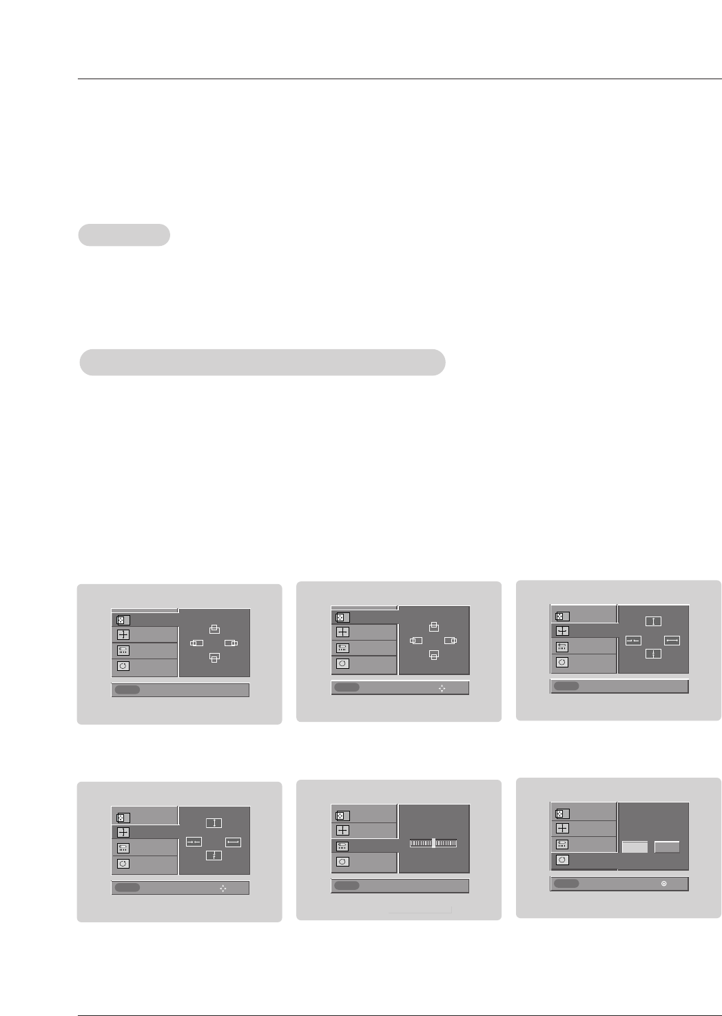
• When RGB connect to PC input and select the RGB-PC in Main Input, this function is used.
• In RGB-DTV mode, SIZE is not available.
Screen Setup for PC mode
•After connecting RGB-PC to PC input and checking the screen quality.
- Display PC Adjust Menu using ADJUST button.
- Position : Adjust the screen position. After displaying the Adjust, select the screen position.
- Size : Adjust the screen size.
(Only available in RGB-PC mode)
- Phase : Adjust the phase of Pixel clock.
- Reset : Initializating Size, Position, Phase adjustment .
Operation
Operation
Adjustment for screen Position, Size, Phase, Reset
Adjustment for screen Position, Size, Phase, Reset
Previous
POSITION
SIZE
PHASE
RESET
Adjust
DD
FFGG
EE
Size
42 DLP Projection TV
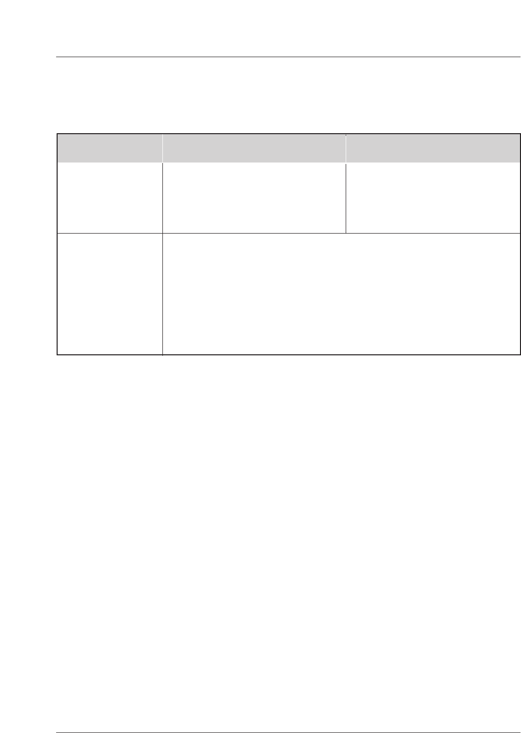
No picture &
No sound
•Check whether the TV is turned on.
•Is the power cord inserted into wall power outlet?
•Test the wall power outlet, plug another product’s power cord into the outlet
where the TV’s power cord was plugged in.
No or poor color
or poor picture
•Select Color in the Picture menu and press the Gbutton.
(Refer to p.24)
•Keep a sufficient distance between the TV and the VCR.
•Activate any function to restore the brightness of the picture.
(If still picture is on the screen for more than 5 minutes, the screen gets dark.)
The Remote Control
doesn’t work
•Check to see if there is any object between the TV and the Remote Control
causing obstruction.
•Are batteries installed with correct polarity (+ to +, - to -)?
(Refer to p.10)
•Correct remote operating mode set: TV, VCR etc.?
•Install new batteries. (Refer to p.10)
Picture OK &
No sound
•Press the VOLUME (G) button.
•Sound muted? Press MUTE button.
Picture appears slowly
after switching on
•This is normal, the image is muted during the TV startup process. Please
contact your service center, if the picture has not appeared after five minutes.
Horizontal/vertical bars
or picture shaking •Check for local interference such as an electrical appliance or power tool.
T
Troubleshooting Checklist
roubleshooting Checklist
Owner’s Manual 43
T
Troubleshooting Checklist
roubleshooting Checklist
Poor TV input
signal •Check ANTENNA and CABLE connection.
No channel or a few
channel •Start EZ Scan.
Poor Video
signal •Check ANTENNA and CABLE connection.
Unsuitable
Aspect Ratio •You can adjust the RATIO button or Aspect Ratio in the OPTION menu.
No output from one of
the speakers •Adjust Balance in the AUDIO menu. (Refer to p.25)
Unusual sound from
inside the TV
•A change in ambient humidity or temperature may result in the unit turning off
and does not indicate a fault with the TV.
44 DLP Projection TV
1. Here’s a great way to keep the dust off your screen for a while. Wet a soft cloth in a mixture of lukewarm water and
a little fabric softener or dish washing detergent. Wring the cloth until it’s almost dry, and then use it to wipe the
screen.
2. Make sure the excess water is off the screen, and then let it air-dry before you turn on your TV.
To remove dirt or dust, wipe the cabinet with a soft, dry, lint-free cloth.
Please be sure not to use a wet cloth.
If you expect to leave your TV dormant for a long time (such as a vacation), it’s a good idea to unplug
the power cord to protect against possible damage from lightning or power surges.
- Early malfunctions can be prevented. Careful and regular cleaning can extend the amount of time you will have your
new TV. Be sure to turn the power off and unplug the power cord before you begin any cleaning.
Cleaning the Screen
Cleaning the Screen
Cleaning the Cabinet
Cleaning the Cabinet
Extended
Extended Absence
Absence
Maintenance
Maintenance
Owner’s Manual 45
•The specifications shown above may be changed without prior notice for quality improvement.
Product Specifications
Product Specifications
MODEL
Horizontal Size (inches)
Height (inches)
Depth (inches)
Weight (lbs.)
Power requirement
Television System
Program Coverage
Power Consumption (W)
Antenna
Audio Output (W)
Supplied Accessories
AC120V ~ 60Hz
NTSC-M, ATSC, 64 & 256 QAM
VHF 2 ~ 13, UHF 14 ~ 69, CATV 1 ~ 135, CADTV 1 ~ 135. DTV 2 ~ 69
210W
75 ohm External Terminal for VHF/UHF
20Wx2
Remote Control, 2 size AA batteries, D-sub 15 pin Cable
Z56DC1D
39.9
29.2
14.4
57.3
Z62DC1D
47.5
33.8
16.1
83.6

46 DLP Projection TV
Notes
Notes
ZENITH ELECTRONICS CORPORATION
DLP Projection TV Limited Warranty - USA
Zenith will repair or replace your product, at Zenith’s option, if it proves to be defective in material or
workmanship under normal use, during the warranty period ("Warranty Period") listed below, effective
from the date ("Date of Purchase") of original consumer purchase of the product. This warranty is
good only to the original purchaser of the product and effective only when used in the United States,
excluding U.S. Territories.
THIS WARRANTY IS IN LIEU OF ANY OTHER WARRANTIES, EXPRESS OR IMPLIED, INCLUD-
ING WITHOUT LIMITATION, ANY WARRANTY OF MERCHANTABILITY OR FITNESS FOR A
PARTICULAR PURPOSE. TO THE EXTENT ANY IMPLIED WARRANTY IS REQUIRED BY LAW,
IT IS LIMITED IN DURATION TO THE EXPRESSED WARRANTY PERIOD ABOVE. ZENITH
WILL NOT BE LIABLE FOR ANY INCIDENTAL, CONSEQUENTIAL, INDIRECT, SPECIAL OR PUNI-
TIVE DAMAGES OF ANY NATURE, EVEN IF ADVISED OF THE POSSIBILITY OF SUCH DAM-
AGES, INCLUDING WITHOUT LIMITATION, LOST REVENUES OR PROFITS, LOST OR COR-
RUPTED PROGRAMMING OR DATA, OR ANY OTHER DAMAGE WHETHER BASED IN CON-
TRACT, TORT, OR OTHERWISE. Some states do not allow the exclusion or limitation of incidental
or consequential damages or limitation on how long an implied warranty lasts, so the above exclu-
sion or limitation may not apply to you. This warranty gives you specific legal rights and you may also
have other rights that may vary from state to state.
WARRANTY PERIOD:
LABOR: One Year from the Date of Purchase.
Parts: One Year from the Date of Purchase.
Halogen Bulb: One Year from the Date of Purchase.
*Parts replaced are warranted for the remaining por-
tion of the original warranty period.
HOW SERVICE IS HANDLED:
In-Home Service: Please retain dealer’s dated bill of
sale or delivery ticket as evidence of the Date of
Purchase for proof of warranty, and submit a copy of the
bill of sale to the service person at the time warranty ser-
vice is provided.
Please call 1-877-9Zenith (1-877-993-6484) to
locate your nearest Zenith Authorized Service
Center.
Replacement parts may be new or factory remanufac-
tured.
LG Customer Interactive Center
201 James Record Road
Huntsville, Alabama 35824
http://www.zenithservice.com
1. Damages or operating problems that result from shipping, installation, adjustment of user con-
trols, calibration, maintenance or failure to maintain, or separate system components; and
2. Damages or operating problems that result from normal wear and tear, misuse, abuse, operation out-
side environmental specifications or contrary to the requirements or precautions in the Operating Guide,
accident, lightning strikes or other natural causes, unauthorized modification or alteration, incorrect electri-
cal current or voltage, reception problem caused by inadequate home antenna or faulty antenna con-
nections, computer software, institutional or commercial use, or other causes not arising out of defect in
material or workmanship.
3. Therefore, the cost of repair or replacement of such a defective product shall be borne by the con-
sumer.
THIS LIMITED WARRANTY DOES NOT APPLY TO:
CUSTOMER INTER-ACTIVE CENTER NUMBERS:
For nearest Authorized Service
Center, Where to buy, Product
Assistance, or Customer Assistance
Call 1-877-9Zenith (1-877-993-6484) (24 hours a day, 365
days per year) and select an appropriate option from the
menu.
Or visit our website at http://www.zenithservice.com
P/N: 3828VA0570A