LG Electronics USA 9QK-DMR3 Wireless Adapter Card User Manual NAM WM1S Manual ENGx
LG Electronics USA Wireless Adapter Card NAM WM1S Manual ENGx
User Manual
Model Name : R3
Product Description.
The Module is an OEM module (35x35mm) based on the SMSC DARR83. It is an uncompressed
wireless digital audio transceiver operating in the 2.4GHz, 5.2GHz and 5.8GHz bands. The wireless
audio link supports up to 4 stereo audio streams and comes together with additional features such as:
data encryption, pairing functionality, bi-directional control data messages, low power audio snooze
mode, WLAN detection and Automatic Frequency Allocation. The DARR83 chip itself provides the
basic functions of Audio Processing and buffering, Data Link Layer and Physical Layer. The module
integrates all functionality for a wireless digital audio connection, comprising:
DARR83 Wireless Audio Processor
2.4GHz/ 5.2GHz/ 5.8 GHz RF Transceiver
Embedded Antennas
Digital audio interfaces (I2S and/or S/PDIF)
I2C control interface
26 pins interface connector (FFC) for power, digital audio and control interface and GPIOs
Built-in 1MB SPI interface Flash 3V 4KB uniform sector
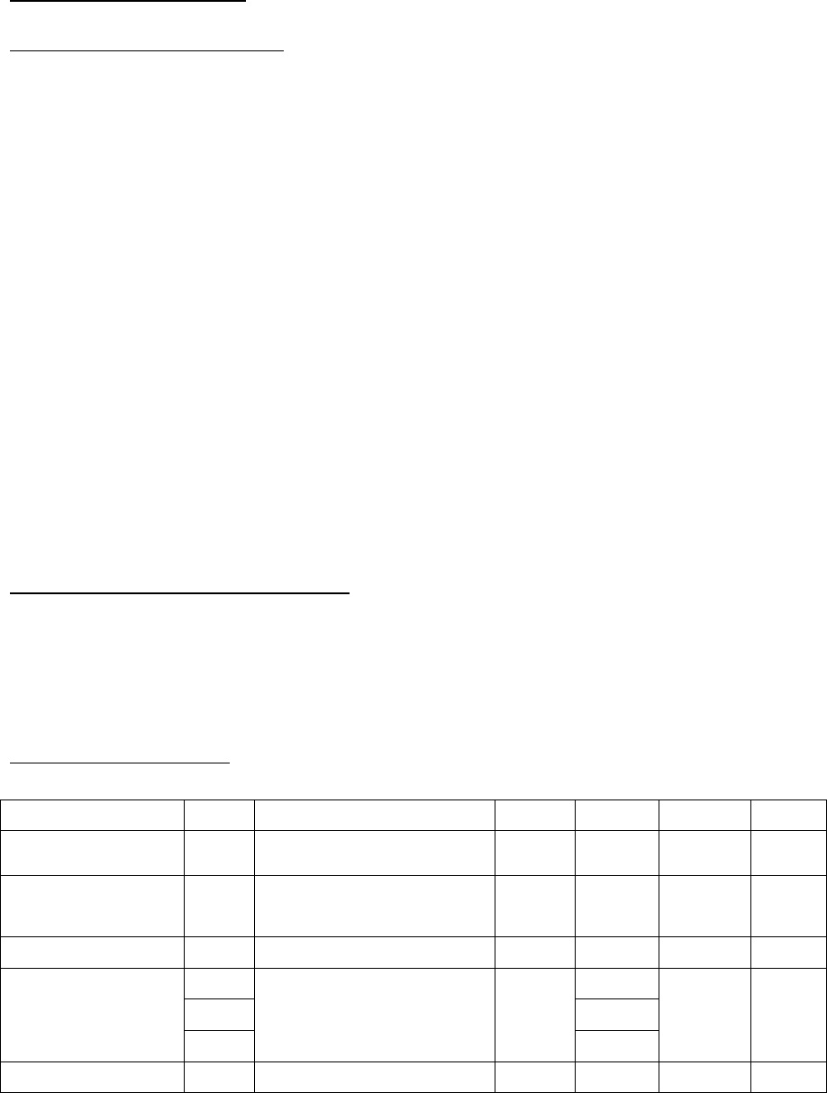
RF Frequency Bandwidth.
2.4GHz: 2400 – 2483.5MHz
5.2GHz: 5150 – 5250MHz
5.8GHz: 5725 – 5875MHz.
RF Performance.
For 2.4GHz application (VCC=3.3V, 25°C)
Parameter Min Typ. Max Units
RF Frequency Range 2400 2483.5 MHz
Number of
RF -Channels
Carries in the spectrum 3
Transmission Power 14 dBm
Frequency
(dynamic or fixed
allocation)
Ch1 2412 MHz
Ch2 2438
Ch3 2464
Channel Spacing 26 MHz
RF Bandwidth Null-to-null 22 MHz
Rx Sensitivity -83 dBm
Antena Diversity Tx/Rx ON
For 5.2GHz application (VCC=3.3V, 25°C)
Parameter Min Typ. Max Units
RF Frequency Range 5150 5250 MHz
Number of
RF -Channels
Carries in the spectrum 3
Transmission Power Depending on antenna
design
9 dBm
Frequency
(dynamic or fixed
allocation)
Ch1 5180 MHz
Ch2 5210
Ch3 5240
Channel Spacing 30 MHz
RF Bandwidth Null-to-null 22 MHz
Rx Sensitivity -81 dBm
Antena Diversity Tx/Rx ON
For 5.8GHz application (VCC=3.3V, 25°C)
Parameter Min Typ. Max Units
RF Frequency Range 5725 5875 MHz
Number of
RF -Channels
Carries in the spectrum 3
Transmission Power Depending on antenna
design
9 dBm
Frequency
(dynamic or fixed
allocation)
Ch1 5736 MHz
Ch2 5762
Ch3 5814
Channel Spacing 26 MHz
RF Bandwidth Null-to-null 22 MHz
Rx Sensitivity -81 dBm
Antena Diversity Tx/Rx ON
Air framing.
Addressing : 24Bit.
Data Message Size : 32Bytes
CRC : 16, 24 and 32Bit
POWER
- Supply Voltage : 3.1V(Min), 3.3V(Typ), 3.5V(Max)
- Peak to Peak Ripple : 100mV(Max).
- Operating Temperature : -10C(Min), 25C(Typ), 60C(Max)
Evaluation Board Usage
The GUI is required to configure the evaluation boards for different applications.
Step 1: Double-click on the GUI Icon or shortcut to run the program.
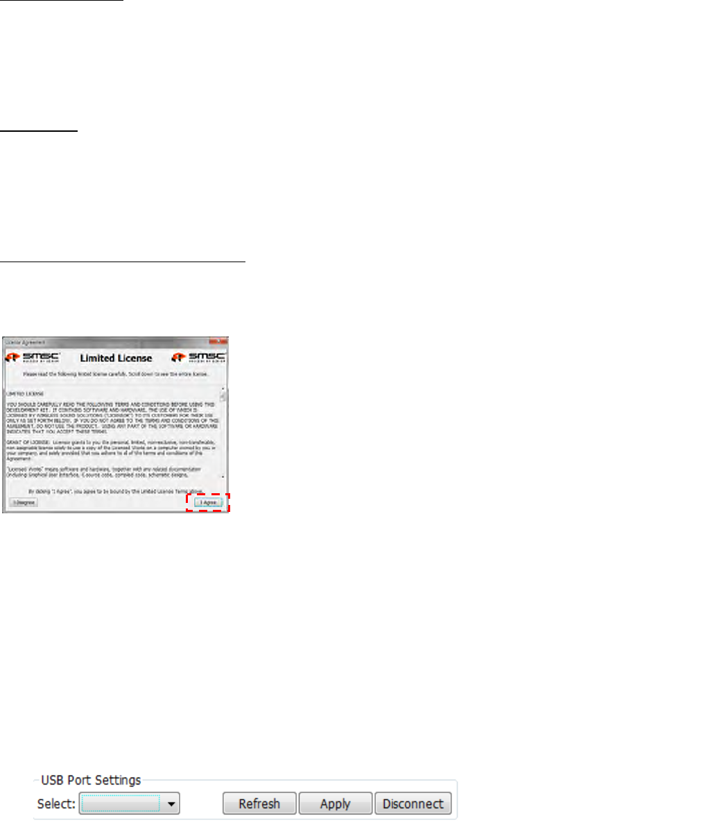
Step 2: Read the limited license carefully.
Click I Agree to proceed (as shown on the right).
Step 3: Make sure the evaluation boards is turned on..
Step 4: Connect the USB cable between your notebook/PC and the evaluation board.
If USB drivers are required to be installed, use the one provided in the GUI package.
.
Step 5: Setup your Com Port in Com Port Settings.
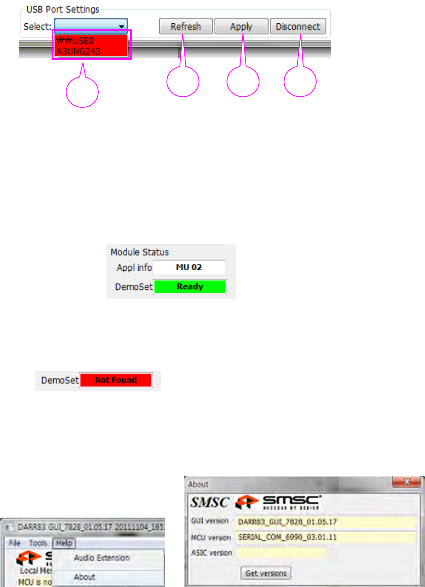
Connect the USB one by one and select each unique USB port setting for each evaluation board.
1) Click the [Refresh] button.
2) Select the EVK ID, for example “A3UNG243”, to access the 4ch EVK connected to the
DWAM83 module.
3) Click the [Apply] button.
4) (Optional) If the “A3UNG243”option cannot be selected from the drop down menu, click the
[Disconnect] button before repeating steps 1 ~ 3.
Once the connection is successful, you should see READY in Module Status.
.
If you see NOT FOUND, please check that the USB cable is properly connected/loose or 5V
DC
Power is plugged in.
Step 6: At the top-left corner of the GUI, click Help and click About.
The current firmware version is shown as Evaluation Kit Version X.X.X.
The current GUI version is shown as Configuration Software GUI Version X.X.X.
2 1 3 4
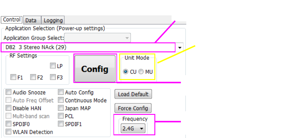
Step 7: Setup your choice of application in the Application Selection (Power-up Settings)
For the explanation for the different kinds of application, you can check the help file that is provided
with the Evaluation board (EVK).
Step 8: Click [Config] button (upon every change) to configure the evaluation board.
Select desired application (depending on the
number of Stereo sources required)
Press this button whenever there are any
changes in this section to update the
module settings
Select the Frequency band (2.4GHz or
5.2GHz or 5.8GHz) to operate after
Configuration
Select CU or MU mode

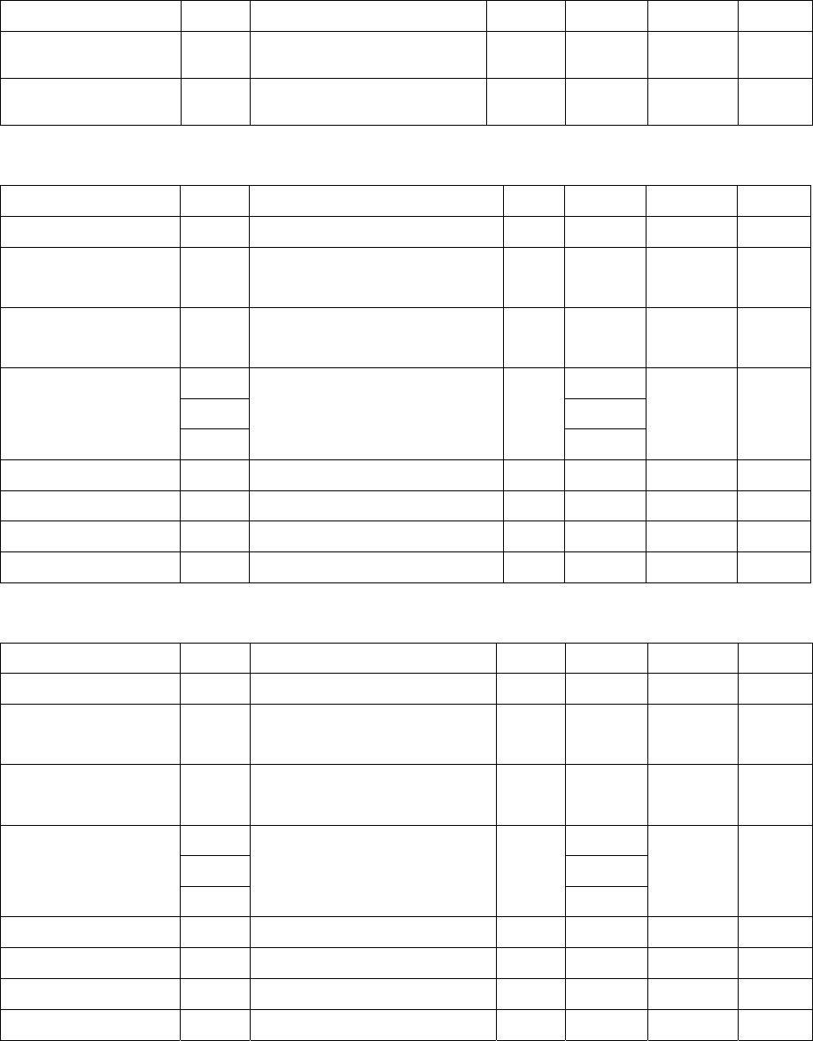
26Pin Interface
PIN # PIN NAME IN/OUT DESCRIPTION
1 VDD Power Input Power: 3.3V.
2 GND Ground GND
3 MCLK In 24.56MHz Master Clock
4 BULE_LED I/O GPIO_13
5 RED_LED I/O GPIO_23
6 SDIO_W (FREQ_BAND) I/O GPIO_5
7 SDIO_X (DATA1) I/O GPIO_11
8 SDIO_Y (DATA2) I/O GPIO_6
9 SDIO_Z (UPLINK DATA) I/O GPIO_12
10 I2C_SCL_SLV I/O I2C SLAVE (SCL)
11 I2C_SDA_SLV I/O I2C SLAVE (SDA)
12 SPI_DI I/O SPI DATA IN
13 SPI_DO I/O SPI DATA OUT
14 SPI_CLK I/O SPI CLOCK
15 SPI_CS I/O SPI_MODE
16 SPI_WP I/O GPIO_1
17 RESET RESET
18 P_SENSE I/O GPIO_2
19 P_CTL I/O GPIO_7
20 PWM_RST I/O GPIO_4
21 AMP_PDN I/O GPIO_3
22 AMP_SD I/O GPIO_14
23 WIRELESS READY I/O GPIO_15
24 BCK (ROLE 1) I/O GPIO_8
25 GND Ground GND
26 LRCK (ROLE 0) I/O GPIO_10
Approval Statements
Hereby, LG Electronics Inc. declares that this device is in compliance with the essential requirements and other relevant provisions of
directive 1999/5/EC.
This device complies with Part 15 of the FCC`s Rules. Operation is subject to the following two Conditions:
1. This device may not cause harmful interference, and
2. This device must accept any interference received, including interference that may cause undesirable operation.
To satisfy FCC exterior labeling requirements, the following text must be placed on the exterior of the end product.
Contains Transmitter module FCC ID: BEJ9QK-DMR
This device complies with Industry Canada license-exempt RSS standard(s). Operation is subject to the following two conditions: (1) this
device may not cause interference, and (2) this device must accept any interference, including interference that may cause undesired
operation of the device.
Cet appareil est conforme avec Industrie Canada exempts de licence standard RSS (s). L'opération est soumise aux deux conditions
suivantes: (1) cet appareil ne peut causer d'interférences, et (2) cet appareil doit accepter toute interférence, y compris les interférences qui
peuvent causer un mauvais fonctionnement de l'appareil.
The host device must be labeled to display the Industry Canada certification number of the module.
Contains transmitter module IC: 2703H-DMR
Le dispositif d'accueil doivent être étiquetés pour afficher le numéro de certification d'Industrie Canada du module.
Contient module émetteur IC : 2703H-DMR
Caution: Any changed or modifications not expressly approved by the party responsible for compliance could void the user`s
authority to operate this equipment.
Attention: Toute changé ou modifications non expressément approuvés par la partie responsable de la conformité pourraient
annuler l'utilisateur `autorité de faire fonctionner cet équipement.
IMPORTANT NOTE
This device complies with FCC & IC radiation exposure limits set forth for an uncontrolled environment. This device should be installed and
operated with minimum distance 20cm between the radiating element of this device and the user. This device must not be co-located or
operating in conjunction with any other antenna or transmitter.
This device is intended only for OEM integrators and following statements shall be included to host user manual
1) The antenna must be installed such that 20cm is maintained between the antenna and users.
2) This module may not be co-located with any other transmitters or antennas.
As long as 2 conditions above are met, further transmitter test will not be required. However, the OEM integrator is still responsible for
testing their end-product for any additional compliance requirements with this module installed.
In the event that these conditions cannot be met, then the FCC & IC authorizations are no longer considered valid and the FCC ID cannot
be used on the final product. In these circumstances, the OEM integrator will be responsible for re-evaluating the end product including this
module and obtaining separate FCC & IC authorizations.
This module has been designed for indoor used only. Therefore the end-product with this module installed is permitted to use
indoors only.
NOTE IMPORTANTE
Cet appareil est conforme aux limites de la FCC et IC exposition aux radiations dans un environnement non contrôlé. Cet appareil doit être
installé et utilisé avec distance minimum de 20cm entre l'élément rayonnant de cet appareil et l'utilisateur. Cet appareil ne doit pas être co-
localisés ou fonctionnant en conjonction avec une autre antenne ou transmetteur.
Cet appareil est conçu uniquement pour les intégrateurs OEM et les déclarations suivantes doivent être incluses à accueillir manuel de l'utilisateur
1) L'antenne doit être installée de telle sorte que 20cm est maintenue entre l'antenne et les utilisateurs
2) Ce module ne peut pas être co-localisés avec les autres émetteurs ou les antennes.
Aussi longtemps que deux conditions précitées sont remplies, le test du transmetteur supplémentaires ne seront pas tenus. Toutefois,
l'intégrateur OEM est toujours responsable de tester leurs produits finis pour toutes les exigences de conformité supplémentaires avec ce
module installé.
Dans le cas où ces conditions ne peuvent pas être remplies, alors la FCC et IC autorisations ne sont plus considérés comme valides et l'ID
de la FCC ne peut pas être utilisé sur le produit final. Dans ces circonstances, l'intégrateur OEM sera responsable de réévaluer le produit
final, y compris l'obtention de ce module et séparée de la FCC et IC autorisations
Ce module a été conçu pour l'intérieur utilisé seulement. Par conséquent, le produit final avec ce module installé est autorisé à
utiliser uniquement à l'intérieur.