LG Electronics USA DU42PX41X 42-inch Plasma Monitor User Manual User s Manual H
LG Electronics USA 42-inch Plasma Monitor User s Manual H
UserManual.wiki
>
LG Electronics USA
>
DU42PX41X User Manual
Users Manual
Navigation menu
Upload a User Manual
Namespaces
Wiki Guide
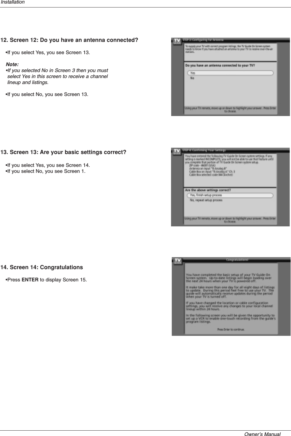
HTML
PDF
Info
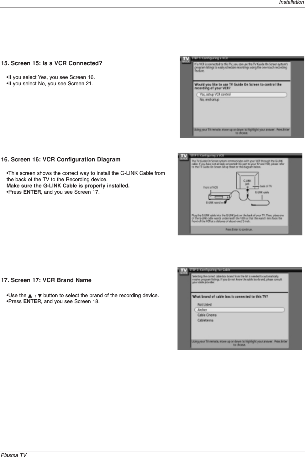
Views
User Manual
Discussion / Help
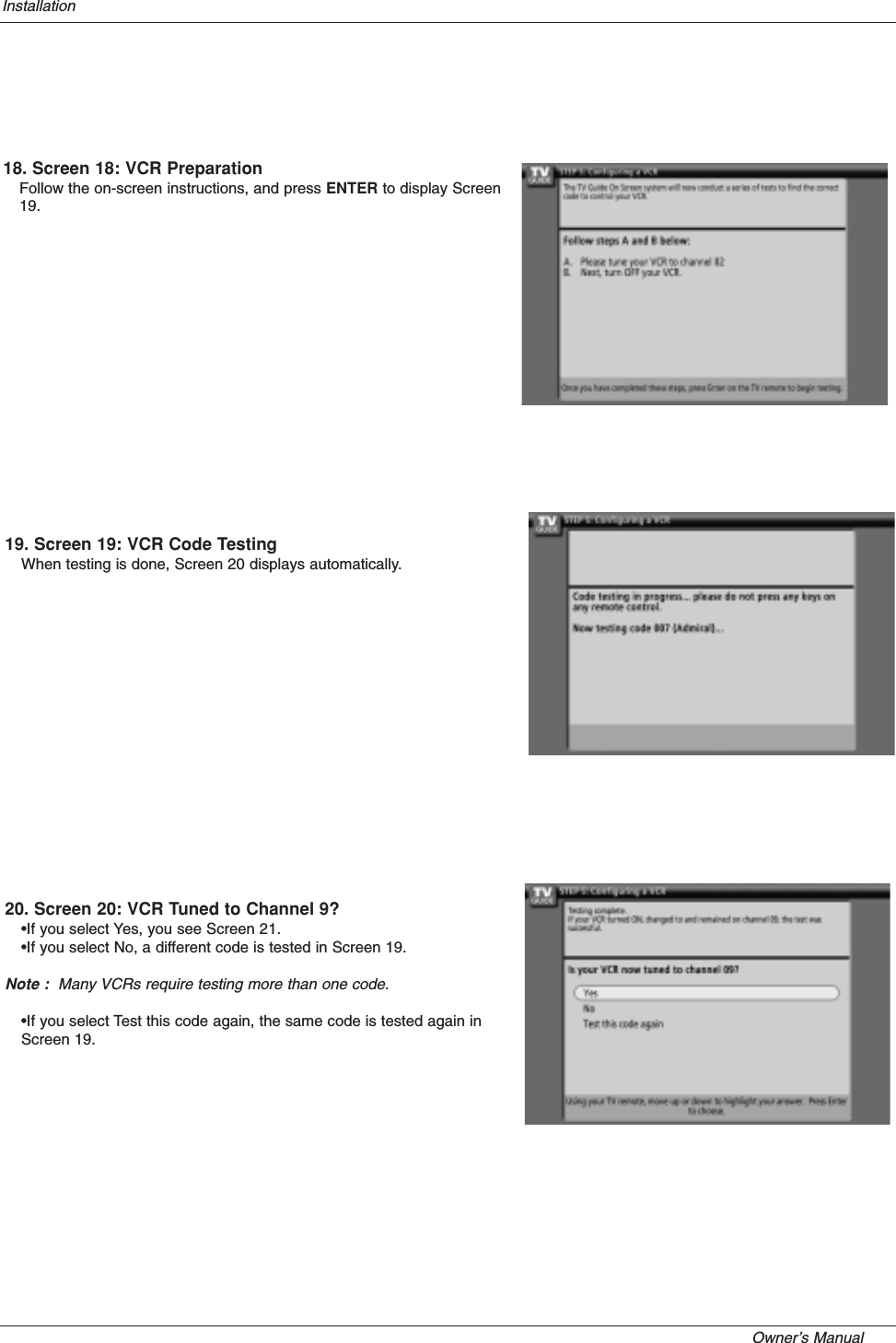
Navigation