LG Electronics USA E2241VX LCD Monitor User Manual W19 2243S T ENG
LG Electronics USA LCD Monitor W19 2243S T ENG
E2241VX User manual

1
This unit has been engineered and manufactured to ensure your personal safety,
however improper use may result in potential electrical shock or fire hazards. In
order to allow the proper operation of all safeguards incorporated in this display,
observe the following basic rules for its installation, use, and servicing.
On Safety
Use only the power cord supplied with the unit. In case you use another power
cord, make sure that it is certified by the applicable national standards if not being
provided by the supplier. If the power cable is faulty in any way, please contact the
manufacturer or the nearest authorized repair service provider for a replacement.
The power supply cord is used as the main disconnection device. Ensure that the
socket-outlet is easily accessible after installation.
Operate the display only from a power source indicated in the specifications of this
manual or listed on the display. If you are not sure what type of power supply you
have in your home, consult with your dealer.
Overloaded AC outlets and extension cords are dangerous. So are frayed power
cords and broken plugs. They may result in a shock or fire hazard. Call your
service technician for replacement.
As long as this unit is connected to the AC wall outlet, it is not disconnected from
the AC power source even if the unit is turned off.
Do not Open the Display:
There are no user serviceable components inside.
There are Dangerous High Voltages inside, even when the power is OFF.
Contact your dealer if the display is not operating properly.
To Avoid Personal Injury :
Do not place the display on a sloping shelf unless properly secured.
Use only a stand recommended by the manufacturer.
Do not drop an object on or apply impact to the product. Do not throw any toys
or objects on the product screen.
It can cause injury to human, problem to product and damage the display.
To Prevent Fire or Hazards:
Always turn the display OFF if you leave the room for more than a short period
of time. Never leave the display ON when leaving the house.
Keep children from dropping or pushing objects into the display's cabinet
openings. Some internal parts carry hazardous voltages.
Do not add accessories that have not been designed for this display.
When the display is to be left unattended for an extended period of time, unplug
it from the wall outlet.
In the presence of thunder and lightning, never touch the power cord and signal
cable because it can be very dangerous. It can cause electric shock.
Important Precautions
2
Important Precautions
On Installation
Do not allow anything to rest upon or roll over the power cord, and do not place the
display where the power cord is subject to damage.
Do not use this display near water such as near a bathtub, washbowl, kitchen sink,
laundry tub, in a wet basement, or near a swimming pool.
Displays are provided with ventilation openings in the cabinet to allow the release
of heat generated during operation. If these openings are blocked, built-up heat
can cause failures which may result in a fire hazard. Therefore, NEVER:
Block the bottom ventilation slots by placing the display on a bed, sofa, rug, etc.
Place the display in a built-in enclosure unless proper ventilation is provided.
Cover the openings with cloth or other material.
Place the display near or over a radiator or heat source.
Do not rub or strike the Active Matrix LCD with anything hard as this may scratch,
mar, or damage the Active Matrix LCD permanently.
Do not press the LCD screen with your finger for a long time as this may cause
some afterimages.
Some dot defects may appear as Red, Green or Blue spots on the screen.
However, this will have no impact or effect on the display performance.
If possible, use the recommended resolution to obtain the best image quality for
your LCD display. If used under any mode except the recommended resolution,
some scaled or processed images may appear on the screen. However, this is
characteristic of the fixed-resolution LCD panel.
Leaving a fixed image on the screen for a long time may cause damage to the
screen and cause image burn-in. Make sure to use a screen saver on the product.
Burn-in and related problems are not covered by the warranty on this product.
Do not shock or scratch the front and sides of the screen with metallic objects.
Otherwise, it may cause damage to the screen.
Make sure the panel faces forward and hold it with both hands to move. If you
drop the product, the damaged product can cause electric shock or fire. Contact
an authorized the service center for repair.
Avoid high temperatures and humidity.
Important Precautions
3
On Cleaning
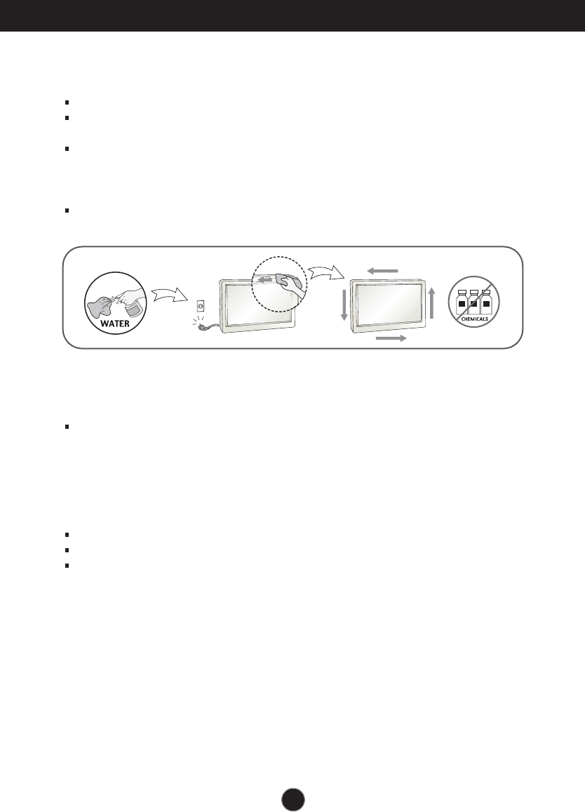
Unplug the display before cleaning the face of the display screen.
Use a slightly damp (not wet) cloth. Do not use an aerosol directly on the display
screen because over-spraying may cause electrical shock.
When cleaning the product, unplug the power cord and scrub gently with a soft
cloth to prevent scratching. Do not clean with a wet cloth or spray water or other
liquids directly onto the product. An electric shock may occur. (Do not use
chemicals such as benzene, paint thinners or alcohol)
Spray water onto a soft cloth 2 to 4 times, and use it to clean the front frame;
wipe in one direction only. Too much moisture may cause staining.
On Repacking
Do not throw away the carton and packing materials. They make an ideal
container in which to transport the unit. When shipping the unit to another
location, repack it in its original material.
On Disposal
The fluorescent lamp used in this product contains a small amount of mercury.
Do not dispose of this product with general household waste.
Disposal of this product must be carried out in accordance to the regulations of
your local authority.

Important Precautions
NOTE
THE MANUFACTURER IS NOT RESPONSIBLE FOR ANY RADIO OR TV
INTRERFERENCE CAUSED BY UNAUTHORIZED MODIFICATIONS TO THIS
EQUIPMENT.SUCH MODIFICATIONS COULD VOID THE USER'S AUTHORITY
NOTE
This epuipment has been tested and found to comply with the limits for a class
B digital device,pursuant to part 15 of the FCC Rules.These limits are designed
to provide reasonable protection against harmful interference in a residential
installation.This equipment generates,uses and can radiate radio frequency
cause harmful interference to radio communications.However,there is no
guarantee that interference will not occur in a particular installation.If this
which can be determined by turning the equipment off and on,the user is
encouraged to try to correct the interference by one or more of the following
measures:
-Reorient or relocate the receiving antenna.
-Increase the separation between the equipment and the receiver.
-Connect the equipment into an outlet on a circuit different from that to which
the receiver is connected.
energy and,if not installed and used in accordance with the instructions,may
equipment does cause harmful interference to radio or television reception,
TO OPERATE THE EQUIPMENT.
-Consult the dealer or an experienced radio/TV technician for help.
A3
4
Accessories
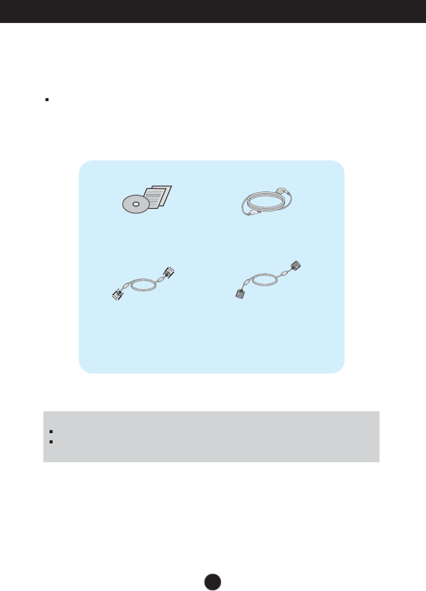
!!! Thank for selecting LGE products !!!
Please make sure the following items are included with your
monitor. If any items are missing, contact your dealer.
User's Guide/Cards Power Cord
15-pin D-Sub Signal Cable
(To set it up, this signal cable may be
attached to this product before
shipping out.)
DVI-D Signal Cable
(This feature is not available in all
countries.)
NOTE
This accessories may look different from those shown here.
User must use shielded signal interface cables (D-sub 15 pin cable, DVI-D cable) with ferrite
cores to maintain standard compliance for the product.
Connecting the Display
5
Before setting up the monitor, ensure that the power to the monitor, the computer
system, and other attached devices is turned off.
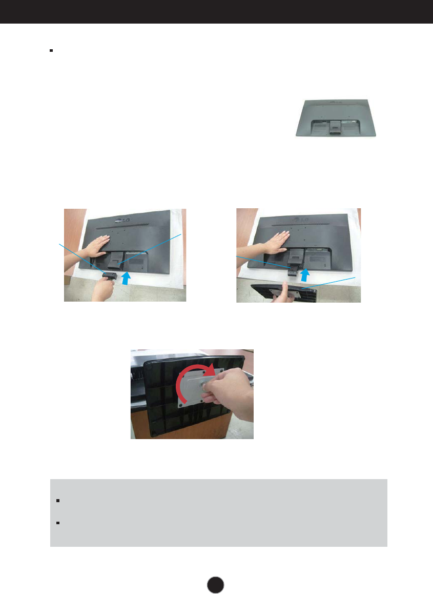
Connecting the stand
1. Place the monitor with its front facing downward on a soft cloth.
2. Assemble the stand Body into the
product in the correct direction as shown in
the picture. Make sure you push it until you
hear it “click”.
3. Assemble the Stand Base(Front,
Rear) into the Stand Body in the
correct direction.
4. Use a coin on the back of the stand base and turn the screw clockwise to
tighten.
5. Once assembled take the monitor up carefully and face the front side.
Important
This illustration depicts the general model of connection. Your monitor may differ from
the items shown in the picture.
Do not carry the product upside down holding only the stand base. The product may
fall and get damaged or injure your foot.
Stand Body Hinge Body
Stand Body
Stand Base
6
Connecting the Display
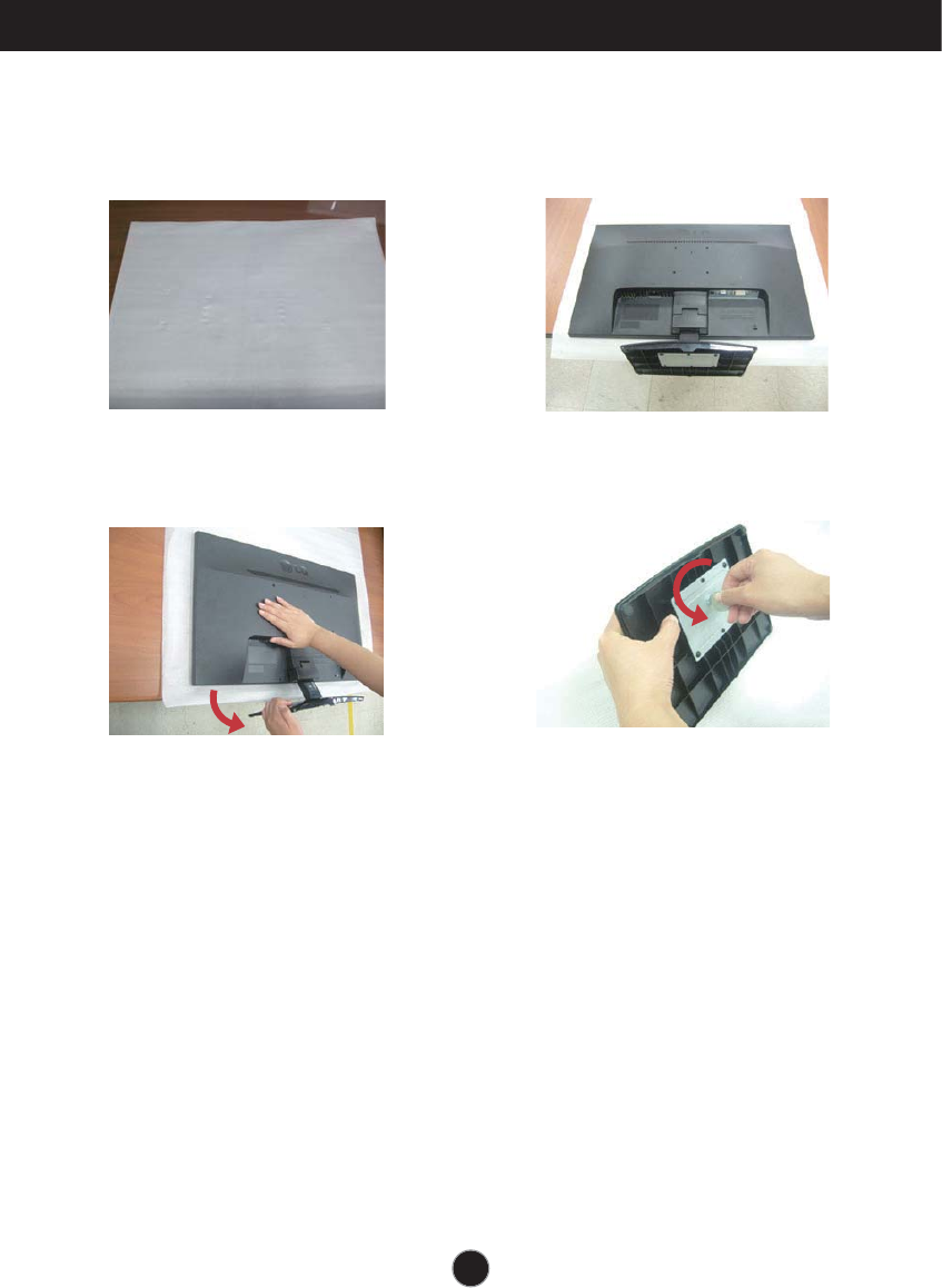
Disassembling the stand
1. Put a cushion or soft cloth on aflat
surface.
3. 4.Remove the Stand Body and Stand
Base from product in correct
direction as shown in the picture.
2. Place the monitor face Down on the
cushion or soft cloth.
Use a coin on the back of the Stand
Base and turn the screw anticlock-
wise to loosen.
Connecting the Display
or tt n p t mon tor n r t at t po r to t mon tor
t omp t r t m an ot r atta t rn o
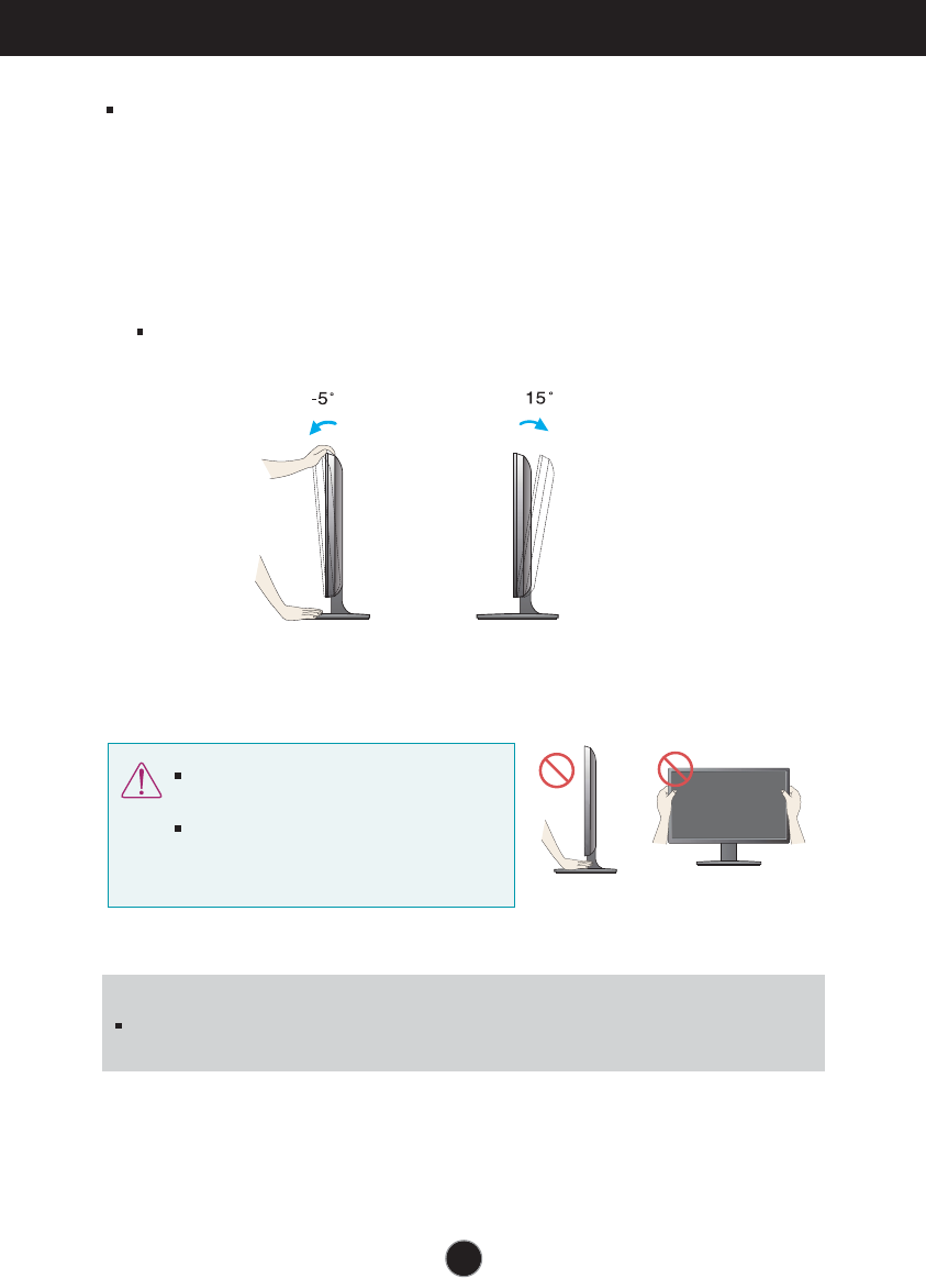
ositioning yo dis ay
trntaatona tt an a o n o
Adjust the position of the panel in arious ways for ma imum comfort.
Tilt Range -5˚ to 15˚
I
t is recommended that in order to maintain an ergonomic and comfortable iewing position,
the forward tilt angle of the monitor should not e ceed degrees.
Do not touch or press the screen when
adjusting the angle of the monitor.
hen adjusting the angle of the screen, do
not put your finger(s) in between the head of
the monitor and the stand body. You can
hurt your finger(s).
•
Connecting the Display
NOTE
‘ Self Image Setting Function’? his function provides the user with optimal display
settings. hen the user connects the monitor for the first time this function automatically adusts
the display to optimal settings for individual input signals.
‘AUTO’ Function? hen you encounter problems such as blurry screen blurred letters screen
flicker or tilted screen while using the device or after changing screen resolution press the
U function button to improve resolution.
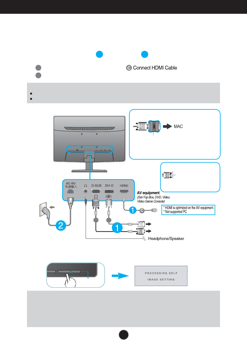
A
B
Connect D -D Digital signal Cable
Connect D-sub nalog signal Cable
1. Before setting up the monitor ensure that the power to the monitor the computer
system and other attached devices is turned off.
2.
Connect signal input cable and power cord in order then tighten the screw
of the signal cable.
PC
PC
A
B
Wall-outlet type
Mac adapter :For Apple Macintosh use, a
separate plug adapter is needed to change the
15 pin high density (3 row) D-sub VGA
connector on the supplied cable to a 15 pin 2
row connector.
When using a D-Sub signal input cable connector
for Macintosh
Varies according to model.
D -D his feature is not available in all countries.
NOTE
his is a simplified representation of the rear view.
his rear view represents a general model your display may differ from the view as shown.
3. Press the power button on the front panel to turn the power on. hen monitor power is
turned on the 'Self Image Setting Function' is e ecuted automatically.
nly nalog ode
Power Button
Connect the signal
input cable and tighten
it up by turning in the
direction of the arrow
as shown in the figure.
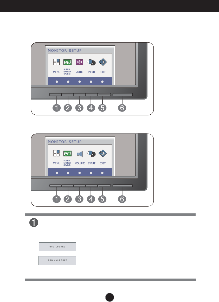
Control Panel unctions
MENU Button
OSD OC ED UN OC ED
his function allows you to lock the current control
settings so that they cannot be inadvertently changed.
Press and hold the MENU button for several seconds.
he message OSD OC ED should appear.
ou can unlock the SD controls at any time by pushing
the MENU button for several seconds. he message
OSD UN OC ED should appear.
or D-SUB and D input
nly for D input
10
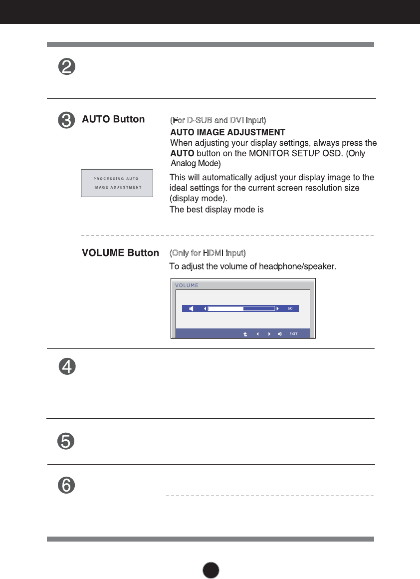
Control Panel Functions
INPUT Button
Use this button to turn the display on or off.
The power indicator stays blue if the display is running
properly (On Mode). If the display is in Sleep Mode
blue.
Power Button &
Power Indicator
When more than two input signals are connected, you can
select the input signal (D-SUB/DVI/HDMI) you want. When
only one signal is connected, it is automatically detected.
The default setting is D-Sub.
(SOURCE Hot key)
Exit the OSD(On Screen Display).
EXIT Button
SUPER ENERGY
SAVING Button
Use this button to enter SUPER ENERGY SAVING
menus.For more information, refer to page 15 .
, the
power indicator is blinking
(For D-SUB and DVI input)
(Only for HDMI input)
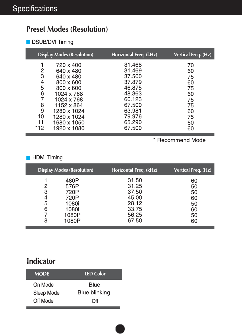
E2241V/E2341V/E2341VG/E2441V:1920 x 1080
e
n.
s.
/ /
.
n
11
12
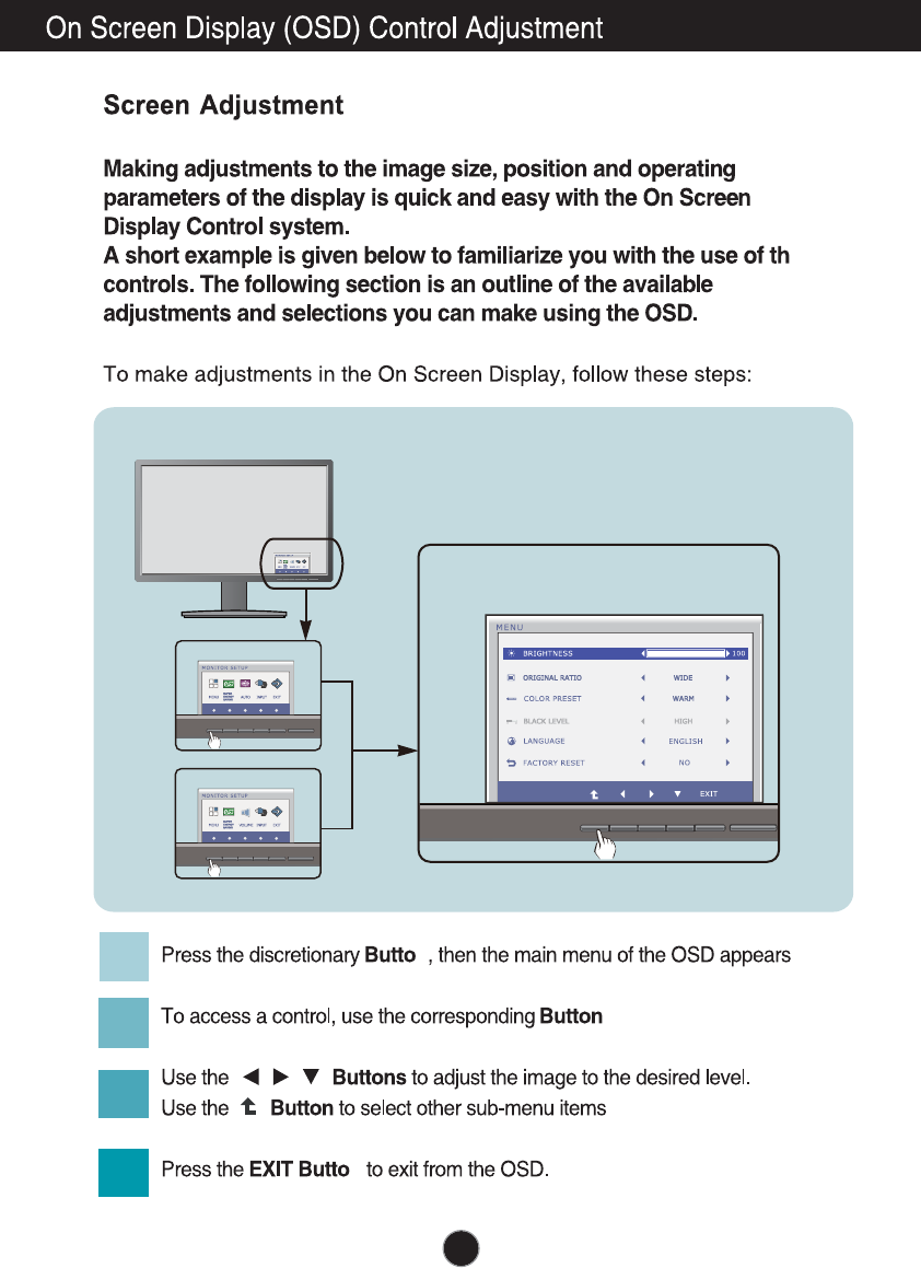
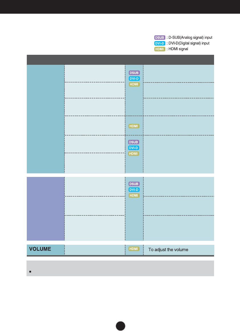
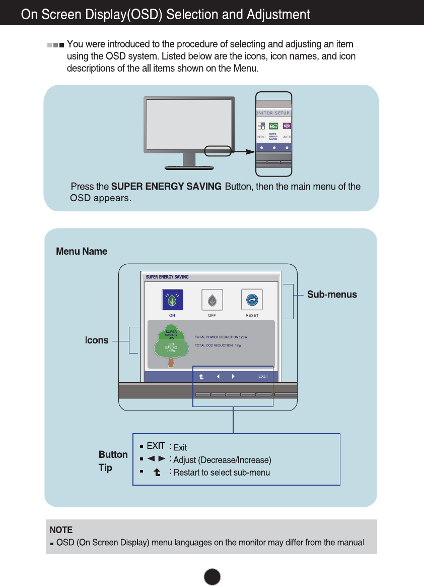
On Screen Display(OSD) Selection and Adjustment
The following table indicates all the On Screen Display control, adjustment,
and setting menus.
To customize the screen status
for a user's operating
environment
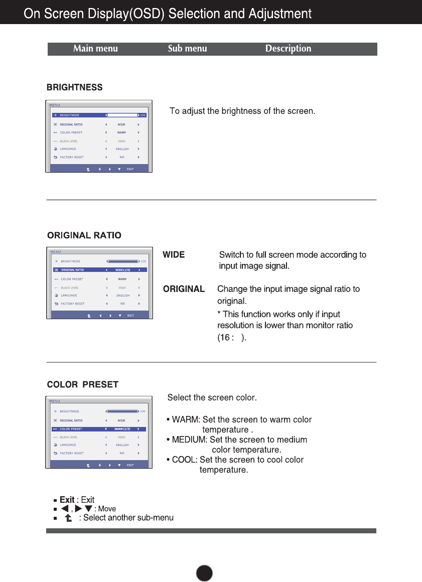
COLOR PRESET
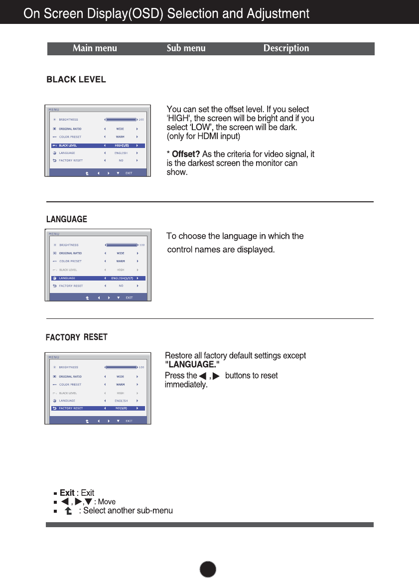
LANGUAGE
MENU To adjust the brightness of
the screen
NOTE
The order of icons may differ depending on the model (13~17).
BRIGHTNESS
ORIGINAL RATIO
To
To adjust the black level of the
screen
adjust the image size
Main menu Sub-menu
Supported input
Description
To customize the color of the
screen
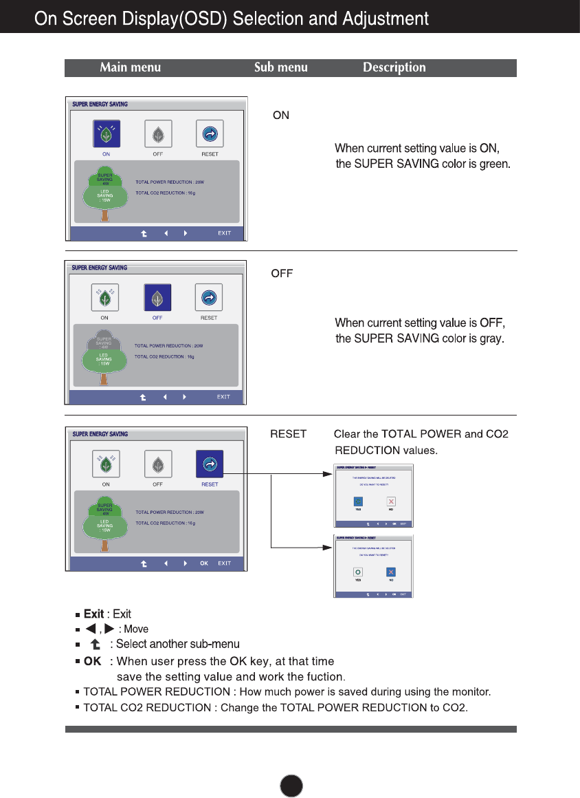
SUPER
ENERGY
SAVING
Turn on the SUPER ENERGY
SAVING function.
Initialize the SUPER ENERGY
SAVING and set to "OFF" mode.
Turn off the SUPER ENERGY
SAVING function.
FACTORY RESET
BLACK LEVEL
ON
OFF
RESET
9
13
,
14
(Only HDMI input)
15
16
Turn on the SUPER ENERGY SAV-
ING function.
Turn off the SUPER ENERGY SAV-
ING function. Now the monitor is
LED SAVING function.
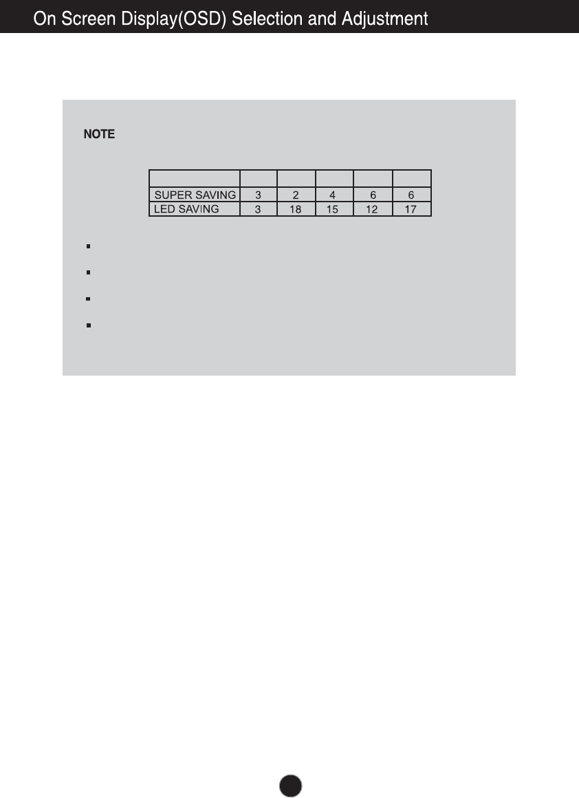
Saving Data depends on the Panel. So, those values should be different from each
panel and panel vendor.
LG accumulate those values using integrated function with 10 minutes broadcast v-
ideo signal.
LED Saving means that how much power can be saved using WLED Panel instead
of CCFL panel.
SUPER Saving means that how much power can be more saved using SUPER E-
NERGY SAVING function.
17
19 inch 20 inch 22 inch 23 inch 24 inch
SAVING DATA:
18
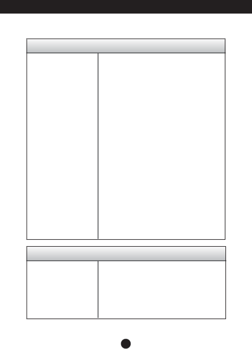
Troubleshooting
No image appears
Check the following before calling for service.
No image appears
Do you see a "OSD LOCKED" message on the screen?
●Is the power cord of the
display connected?
●Is the power indicator
light on?
●Is the power indicator
flickering?
●Do you see an "OUT OF
RANGE" message on
the screen?
●Do you see a "CHECK
SIGNAL CABLE"
message on the
screen?
•
Check and see if the power cord is connected
properly to the power outlet.
•
Press the Power button.
•
If the display is in power saving mode, try moving
the mouse or pressing any key on the keyboard to
bring up the screen.
• Try to turn on the PC
.
•
This message appears when the signal from the
PC (video card) is out of horizontal or vertical
frequency range of the display. See the
'Specifications' section of this manual and
configure your display again.
•
This message appears when the signal cable
between your PC and your display is not
connected. Check the signal cable and try again.
• You can secure the current control settings,
so that they cannot be inadvertently changed.
You can unlock the OSD controls at any time
by pushing the MENU button for several
seconds: the message
“OSD UNLOCKED” will appear.
●
Do you see “OSD
LOCKED” when you
push MENU button?
19
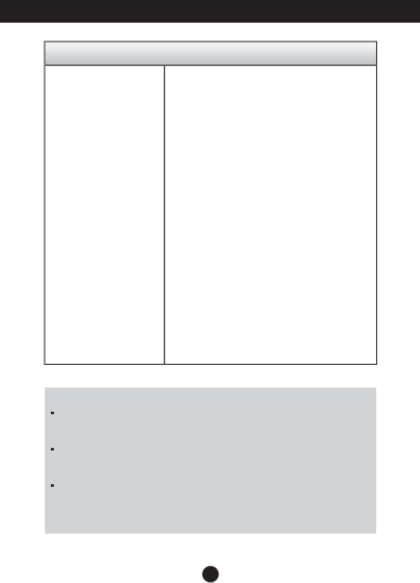
Troubleshooting
Display image is incorrect
●Display Position is
incorrect.
●On the screen
background, vertical
bars or stripes are
visible.
●Any horizontal noise
appearing in any
image or characters
are not clearly
portrayed.
•
Press the AUTO button to automatically adjust
your display image to the ideal setting.
•
Press the AUTO button to automatically adjust
your display image to the ideal setting.
•
Press the AUTO button to automatically adjust
your display image to the ideal setting.
•
Check Control Panel --> Display --> Settings
and adjust the display to the recommended
resolution or adjust the display image to the ideal
setting. Set the color setting higher than 24 bits
(true color).
IMPORTANT
Check Control Panel --> Display --> Settings and see if the frequency or the
resolution were changed. If yes, readjust the video card to the recommend
resolution.
If the recommended resolution (optimal resolution) is not selected, letters may be
blurred and the screen may be dimmed, truncated or biased. Make sure to select
the recommend resolution.
The setting method can differ by computer and O/S (Operation System),
and resolution mentioned above may not be supported by the video card
performance. In this case, please ask to the computer or the video card
manufacturer.
20
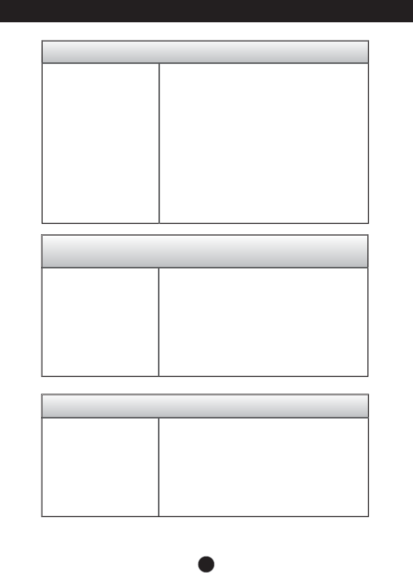
Display image is incorrect
Troubleshooting
●The screen color is
mono or abnormal.
●The screen blinks.
•
Check if the signal cable is properly connected
and use a screwdriver to fasten if necessary.
•
Make sure the video card is properly inserted in
the slot.
•
Set the color setting higher than 24 bits (true color)
at Control Panel - Settings.
•
Check if the screen is set to interlace mode and if
yes, change it to the recommend resolution.
Do you see an "Unrecognized monitor, Plug&Play (VESA
DDC) monitor found" message?
●
Have you installed the
display driver?
•
Be sure to install the display driver from the display
driver CD (or diskette) that comes with your
display. Or, you can also download the driver from
our web site: http://www.lg.com.
•
Make sure to check if the video card supports
Plug&Play function.
The Audio function is not working
●
Picture OK & No sound.
• Check whether volume is "0".
• Check sound muted.
• HDMI cable installed properly.
• Head phone cable installed properly.
• Check sound format. Not supply to compressed
sound format.
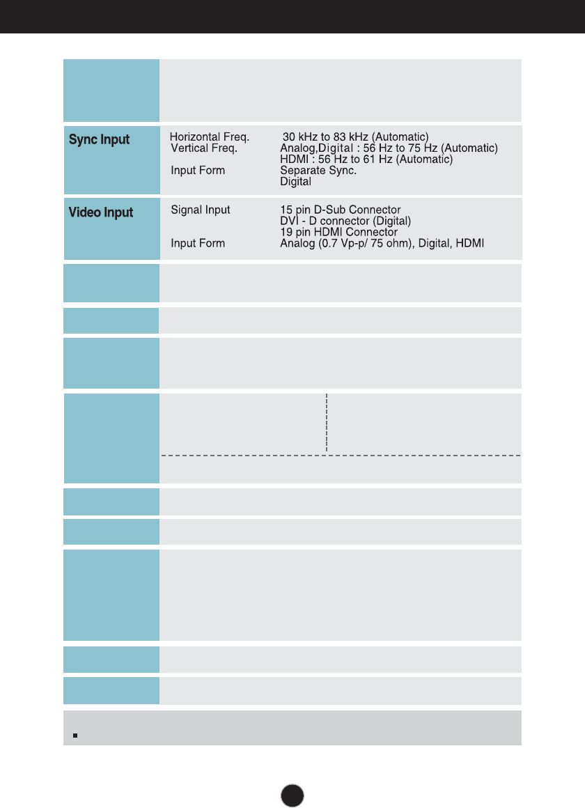
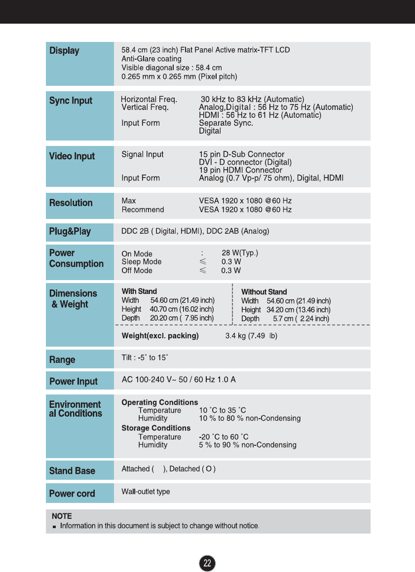
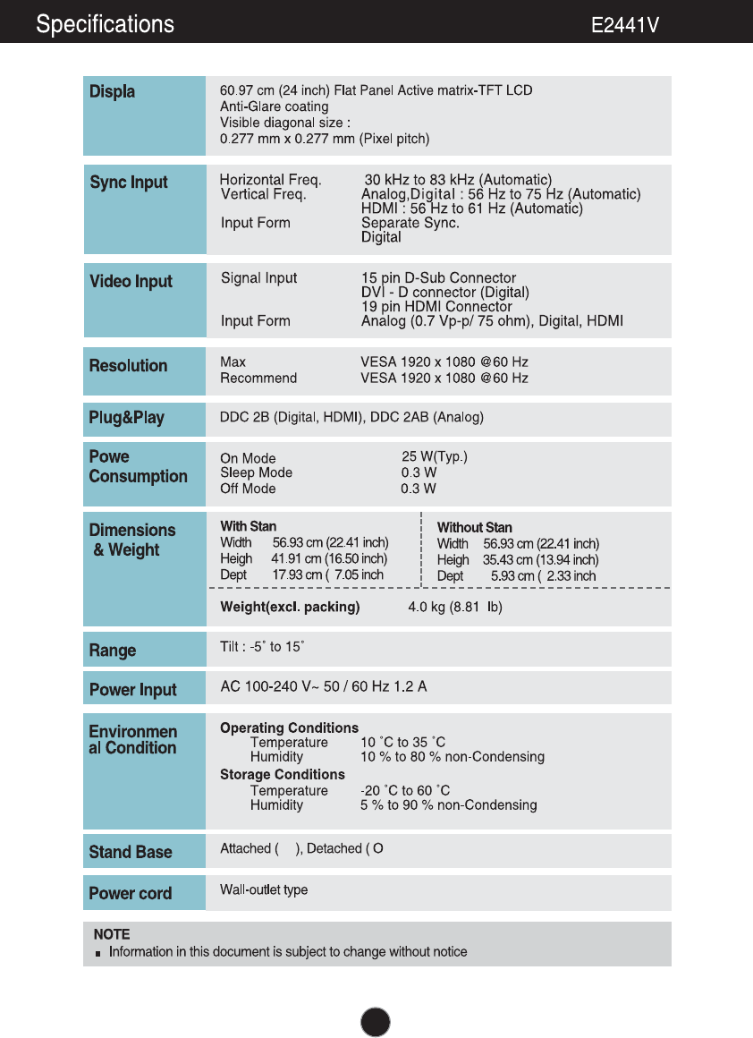
Specifications
. cm ( . inch) Flat Panel Acti e matri TFT CD
Anti lare coating
isible diagonal si e
.
cm
. mm . mm (Pi el pitch)
pa
Ma SA
Recommend SA
oton
a
On Mode
(Typ.)
Sleep Mode İ.
Off Mode İ.
or
on mpt on
p rat n on t on
Temperature 10 ˚C to 35 ˚C
umidity to non Condensing
tora on t on
Temperature -20 ˚C to 60 ˚C
umidity to non Condensing
n ronm nt
aonton
t tan
idth . cm ( . inch)
eigh . cm ( . inch)
Depth . cm ( . inch)
tpan . kg ( . lb)
mn on
t
Tilt : -5˚ to 15˚
an
Attached ( ), Detached ( O )
tan a
all outlet type
oror
DDC B(Digital, DM ), DDC AB(Analog)
tot tan
idth . cm ( . inch)
eight . cm ( . inch)
Depth . cm ( . inch)
nformation in this document is subject to change without notice.
AC . A
o r Inp t
Specifications E2341V/E2341VG
.
cm
y
İ
İ
r
t
s
d
t
h
d
t
.
nstalling the all mount plate
This monitor satisfies the specifications of the Wall mount plate or
the interchange device.
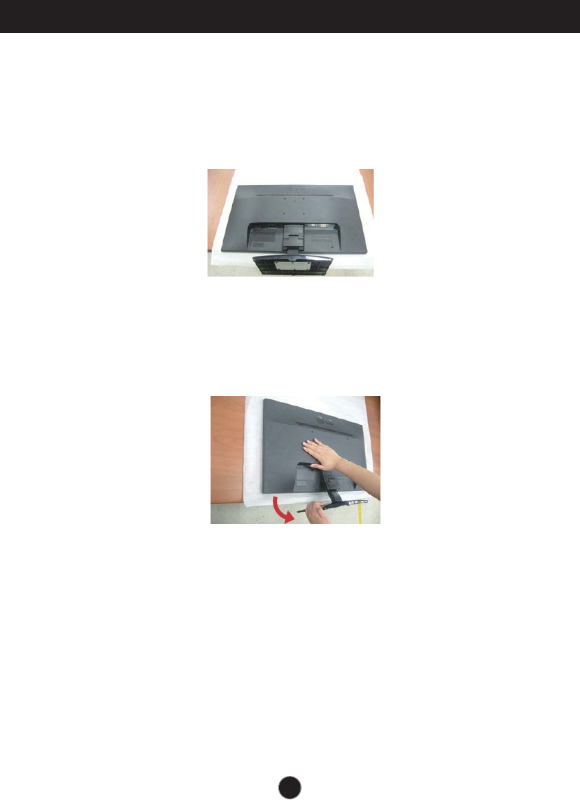
1. Place the monitor with its front facing downward on a soft cloth.
2. Remove the Stand Body and Stand Base from product in correct direction
as shown in the picture.
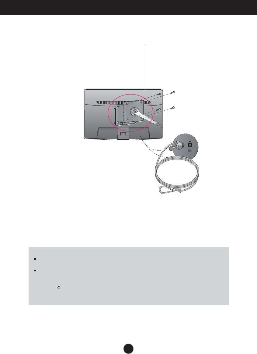
nstalling the all mount plate
Wall mount plate Separate purchase
his is stand-type or wall mount type and is
connectable with all mount plate.
Please refer to the installation guide for more
details which is provided when all mount
plate is purchased.
ensington Security Slot
Connected to a locking cable that can
be purchased separately at most
computer stores.
Screw Mounting Interface Dimension
ole spacing mm mm.
3.
nstall the all mount plate.
NOTE
S compatible only with respect to screw mounting interface dimensions and mounting screw
specifications
Please use S standard as below.
. mm and under . inch
- all ount Pad hickness . mm
- Screw . mm Pitch . mm ength mm
. mm and above . inch
- Please use S standard wall mount pad and screws.

Make sure to read the Safety Precautions
before using the product.
Keep the OWNER’S MANUAL(CD) in an
accessible place for furture reference.
The model and serial number of the SET is
located on the back or one side of the SET.
Record it below should you ever need service.
MODEL
SERIAL
As an ENERGY STAR Partner LGE U. S. A.,Inc.
has determined that this product meets the
ENERGY STAR guidelines for energy efficiency.
ENERGY STAR is a set of power-saving
guidelines issued by the U.S.Environmental
Protection Agency(EPA).