LG Electronics USA E2442VA Part15 Subpart B-LCD Monitor User Manual BEJE2742VA 1
LG Electronics USA Part15 Subpart B-LCD Monitor BEJE2742VA 1
Contents
- 1. BEJE2742VA_User Manual 1
- 2. BEJE2742VA_User Manual 2
- 3. BEJE2742VA_User Manual 3
BEJE2742VA_User Manual 1

www.lg.com
OWNER’S MANUAL
LED LCD MONITOR
E2342V
E2442V
E2742V
Please read this manual carefully before operating
your set and retain it for future reference.
LED LCD MONITOR MODEL
ENGLISH

2
ENG
ENGLISH
TABLE OF CONTENTS
CONTENTS
3 ASSEMBLING AND PREPAR-
ING
3 Unpacking
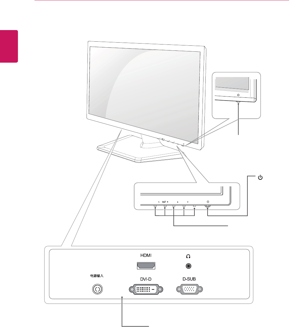
4 Parts and buttons
6 Setting up the Monitor set
6 - Attaching the Stand
6 - Detaching the Stand
7 - Mounting on a table
8 - Mounting on a wall
10 USING THE MONITOR SET
10 Connecting to a PC
10 - D-SUB connection
10 - DVI-D connection
10 - HDMI connection
12 CUSTOMIZING SETTINGS
12 Accessing The Main Menus
13 Customizing Settings
13 - Menu Settings
14 - PICTURE
15 - COLOR
16 - DISPLAY
16 - VOLUME
17 - OTHERS
18 SUPER ENERGY SAVING
19 MODE Setting
20 TROUBLESHOOTING
22 SPECIFICATIONS
22 E2342V
23 E2442V
25 Preset Modes (Resolution)
25 Indicator
24 E2742V
ASSEMBLING AND PREPARING
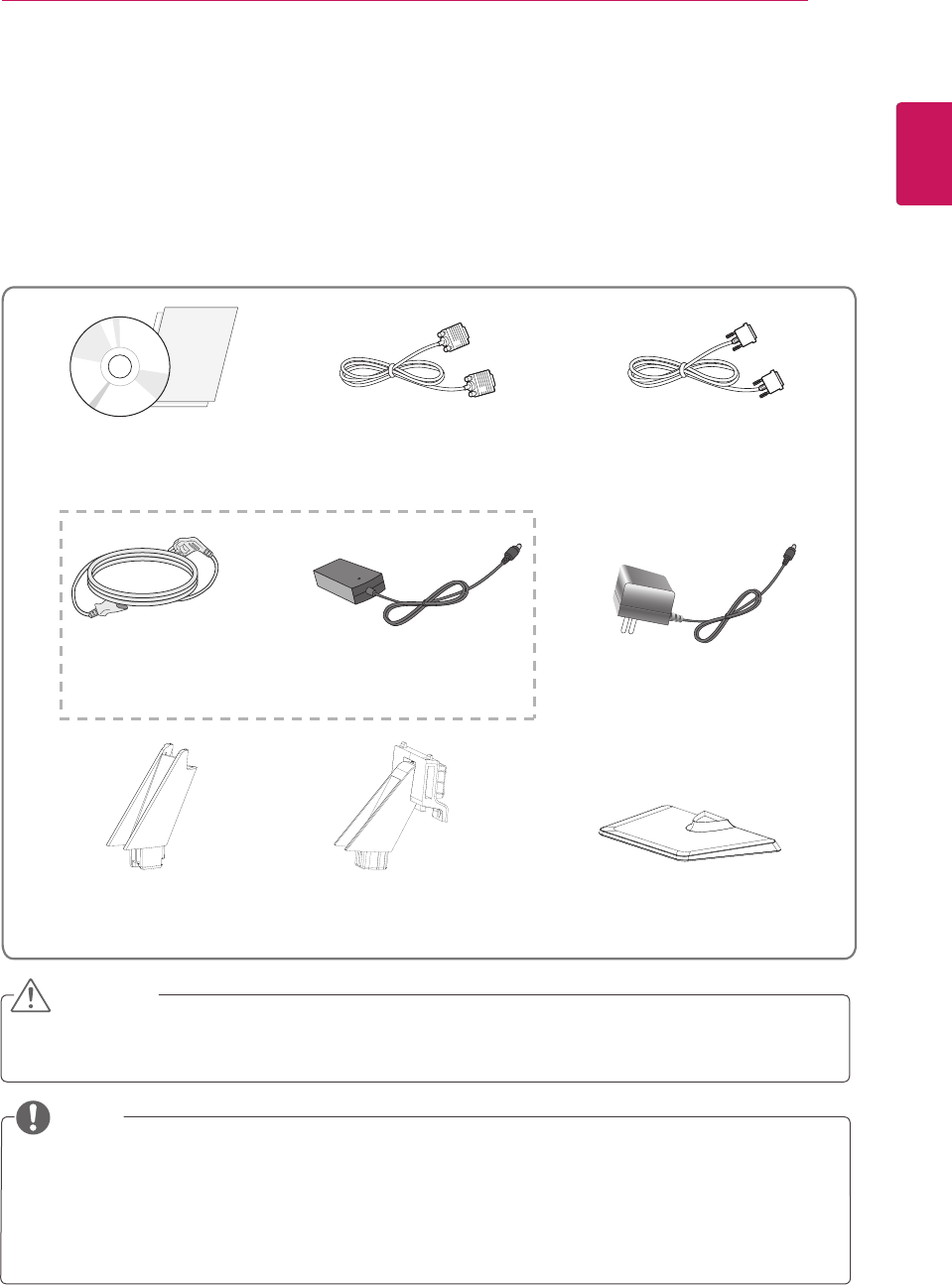
Unpacking
Check your product box for the following items. If there are any missing accessories, contact the local
dealer where you purchased your product. The illustrations in this manual may differ from the actual product
and accessories.
yDo not use any unapproved accessories to ensure the safety and product life span.
yAny damages or injuries by using unapproved accessories are not covered by the warranty.
yThe accessories supplied with your product may vary depending on the model.
yProduct specifications or contents in this manual may be changed without prior notice due to upgrade
of product functions.
CAUTION
NOTE
3
ENG
ENGLISH
ASSEMBLING AND PREPARING
CD(Owner's Manual) /
Card D-SUB Cable DVI-D Cable
(This cable is not included in all
countries.)
Power Cord AC-DC Adapter
Stand Base
Stand Body Stand Body
AC-DC adapter
(Depending on the country)
or
(Depending on the country)
( E2342V /E2442V )
( E2742V )
Setting up the Monitor set
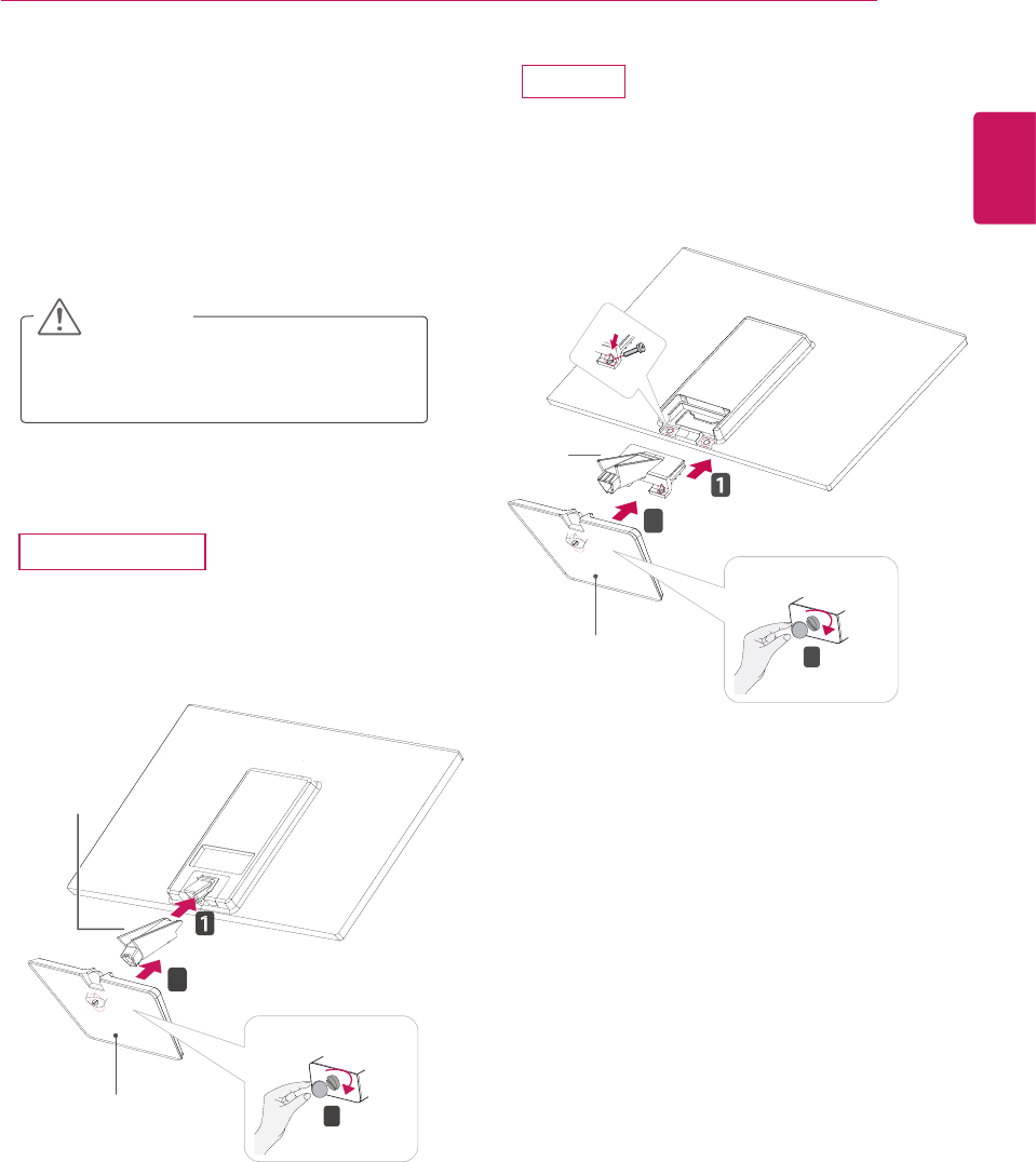
Attaching the Stand
1 Place the Monitor set with the screen side
down on a flat and cushioned surface.
Lay a foam mat or soft protective cloth
on the surface to protect the screen from
damage.
CAUTION
2
Attach the Stand body and then attach the Stand
Base,then tighten the screw to the right with a
Coin.
5
ENG
ENGLISH
ASSEMBLING AND PREPARING
E2742V
Use two screw to assemble the Stand Body and
back cover, attach the stand base and then
tighten the screw to the right with a Coin.
Stand Base 3
2
Stand Base
2
3
Stand Body
Stand Body
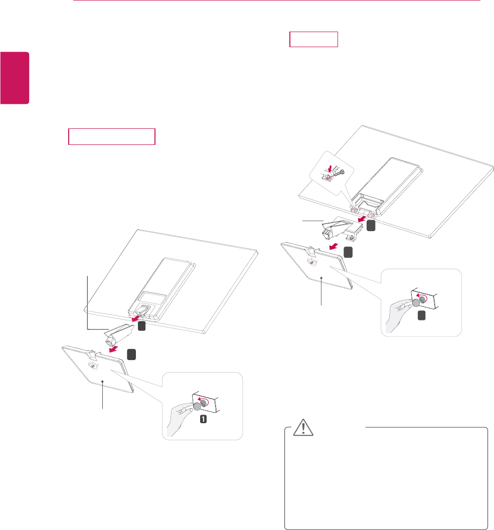
E2342V/E2442V
CAUTION
y
This illustration depicts the general model of
connection. Your monitor may differ from the
items shown in the picture.
y
Do not carry the product upside down holding
only the stand base. The product may fall
and get damaged or injure your foot.
E2742V
Stand Base 1
2
3
Stand Body
Turn the screw to the left with a Coin, and then
pull out the Stand Base from the Stand Body.
Remove 2 screws and pull out the Stand Body
from the Monitor set.
Detaching the Stand
1 Place the Monitor set with the screen side
down on a flat and cushioned surface.
2
Turn the screw to the left with a Coin, and then
pull out the Stand Base from the Stand Body,
then pull out the Stand Body from the Monitor
set .
Stand Base
2
3
Stand Body
6
ENG
ENGLISH
ASSEMBLING AND PREPARING
E2342V/E2442V
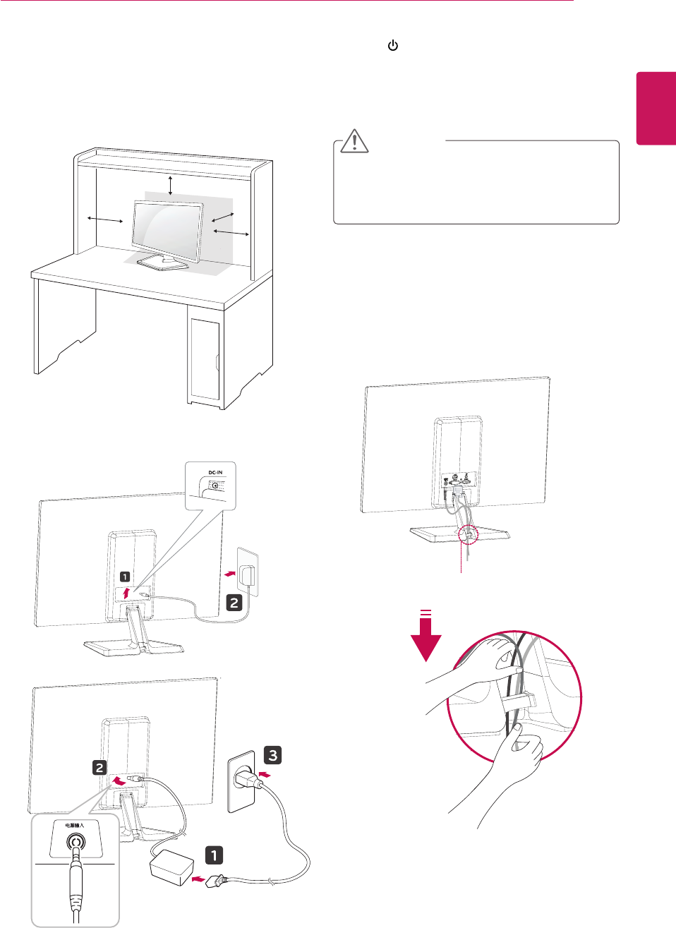
Mounting on a table
1 Lift and tilt the Monitor set into its upright
position on a table.
Leave a 10 cm (minimum) space from the wall
for proper ventilation.
2 Connect the AC-DC adapter and Power Cord
to wall outlet
3 Press (Power) button on the bottom switch
panel to turn the power on.
CAUTION
Unplug the power cord before moving the
Monitor to another location. Otherwise electric
shock may occur.
10 cm
10 cm
10 cm
10 cm
ENG
ENGLISH
ASSEMBLING AND PREPARING 7
Using the cable holder
Cable holder
电源输入/
DC-IN
/
or
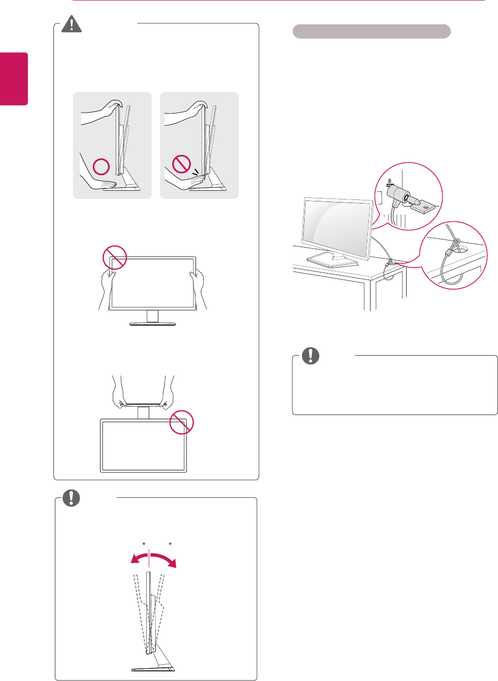
Tilt from +20 to -5 degrees up or down to adjust
the angle of the Monitor set to suit your view.
NOTE
Front Rear
Using the Kensington security system
The Kensington security system connector is
located at the back of the Monitor set. For more
information of installation and using, refer to the
manual supplied with the Kensington security
system or visit
http://www.kensington.com
.
Connect the Kensington security system cable
between the Monitor set and a table.
The Kensington security system is optional.
You can obtain it from most electronics stores.
NOTE
20- 5
8
ENG
ENGLISH
ASSEMBLING AND PREPARING
ENGLISH
When you adjust the angle, do not hold the
bottom of the Monitor set frame as shown on
the following illustration, as may injure your
fingers.
Do not touch or press the screen when
adjusting the angle of the monitor.
WARNING
Do not hold this set like below picture.
Monitor screen can detach from stand base
and injure your body.
yDisconnect the power cord first, and then
move or install the Monitor set. Otherwise
electric shock may occur.
yIf you install the Monitor set on a ceiling or
slanted wall, it may fall and result in severe
injury.
yUse only an authorized LG wall mount
and contact the local dealer or qualified
personnel.
y Do not over tighten the screws as this may
cause damage to the Monitor set and void
your warranty.
y Use only screws and wall mounts that
meet the VESA standard. Any damages
or injuries by misuse or using an improper
accessory are not covered by the warranty.
yUse the screws that are listed on the VESA
standard screw specifications.
yThe wall mount kit will include an installation
manual and necessary parts.
yThe wall mount bracket is optional. You can
obtain additional accessories from your local
dealer.
yThe length of screws may differ depending
on the wall mount. Be sure to use the proper
length.
yFor more information, refer to the
instructions supplied with the wall mount.
CAUTION
NOTE
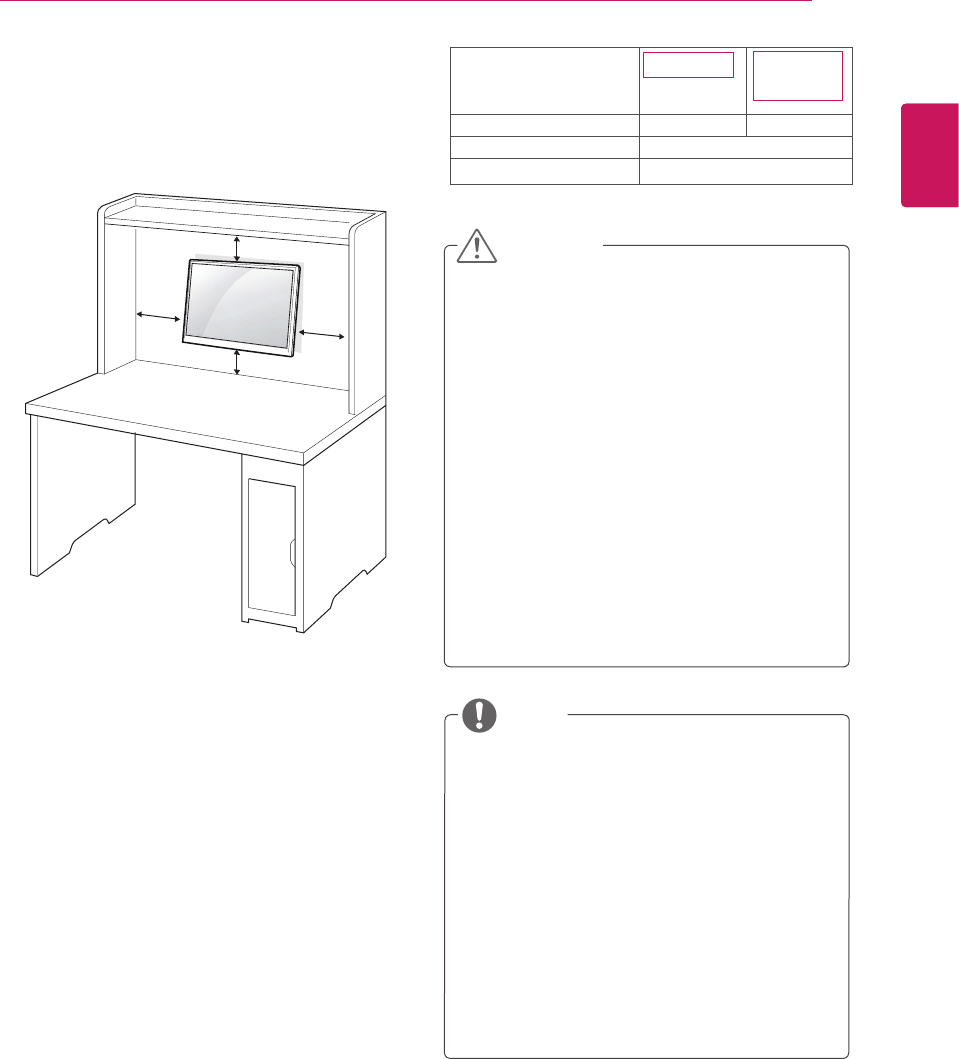
Model E2342V
VESA (A x B) 75 x 75
Standard screw M4
Number of screws 4
100 x 100
E2442V
E2742V
Mounting on a wall
For proper ventilation, allow a clearance of 10 cm
on each side and from the wall. Detailed
instructions are available from your dealer, see the
optional Tilt Wall Mounting Bracket Installation and
Setup Guide.
If you intend to mount the Monitor set to a wall,
attach Wall mounting interface (optional parts) to
the back of the set.
When you install the Monitor set using a wall
mounting interface (optional parts), attach it
carefully so it will not drop.
1 Please, Use the screw and wall mount interface
in accordance with VESA Standards.
2 If you use screw longer than standard, the
monitor might be damaged internally.
3 If you use improper screw, the product might be
damaged and drop from mounted position. In
this case, LG Electronics is not responsible for
it.
4 VESA compatible.
5 Please use VESA standard as below.
784.8 mm (30.9 inch) and under
* Wall Mount Pad Thickness : 2.6 mm
* Screw : Φ 4.0 mm x Pitch 0.7 mm x
Length 10 mm
787.4 mm (31.0 inch) and above
* Please use VESA standard wall mount pad
and screws.
10 cm
10 cm
10 cm
10 cm
9
ENG
ENGLISH
ASSEMBLING AND PREPARING
USING THE MONITOR SET
Connecting to a PC
yYour Monitor set supports Plug & Play*.
*Plug & Play: A PC recognizes a connected
device that users connect to a PC and turn
on, without device configuration or user
intervention.
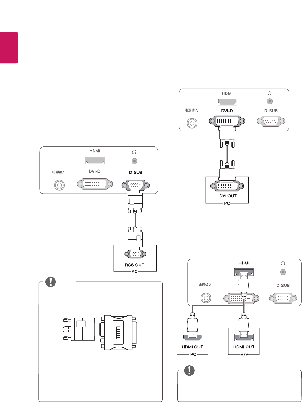
D-SUB connection
Transmits analog video from your PC to the
Monitor set. Connect the PC and the Monitor set
with the supplied D-sub 15 pin signal cable as
shown in the following illustrations.
yMac adapter
For Apple Macintosh use, a separate plug
adapter is needed to change the 15 pin
high density (3 row) D-SUB VGA connector
on the supplied cable to a 15 pin 2 row
connector.
yWhen using a D-Sub signal input cable
connector for Macintosh
yIf you use HDMI PC, it can cause compatibility
problem.
NOTE
NOTE
DVI-D connection
Transmits a digital video signal from your PC to
the Monitor set. Connect the PC and the Monitor
set with a DVI cable as shown in the following
illustrations.
HDMI connection
Transmits the digital video and audio signals from
your PC or A/V to the Monitor set. Connect the PC
or A/V and the Monitor set with the HDMI cable as
shown in the following illustrations.
DC-IN
/
DC-IN
/
DC-IN
/
10
ENG
ENGLISH
USING THE MONITOR SET
yWhen you want to use two PC in our Monitor,
please connect the signal cable(D-SUB/
DVI-D/HDMI) respectively in Monitor set.
yIf you turn the Monitor set on while it is cold,
the screen may flicker. This is normal.
ySome red, green, or blue spots may appear
on the screen. This is normal.
y"Self Image Setting" Function.
This function provides the user with optimal
display settings.When the user connects
the monitor for the first time, this function
automatically adjusts the display to optimal
settings for individual input signals.(Only
supported in Analog Mode)
y‘AUTO’ Function.
When you encounter problems such as
blurry screen, blurred letters, screen flicker
or tilted screen while using the device or
after changing screen resolution, press the
AUTO function button to improve resolution.
(Only supported in Analog Mode)
NOTE NOTE
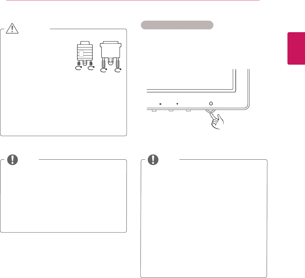
yConnect the signal
input cable and tighten
it by turning the screws
clockwise.
yDo not press the screen with your finger for
a long time as this may result in temporary
distortion on the screen.
yAvoid displaying a fixed image on the
screen for a long period of time to prevent
image burn. Use a screensaver if possible.
CAUTION Self Image Setting Function
Press the power button on the bottom panel to
turn the power on. When monitor power is turned
on, the "Self Image Setting" Function is executed
automatically. (Only supported in Analog Mode)
11
ENG
ENGLISH
USING THE MONITOR SET
INPUT / EXIT
MODE / AUTO /
CUSTOMIZING SETTINGS
1
2
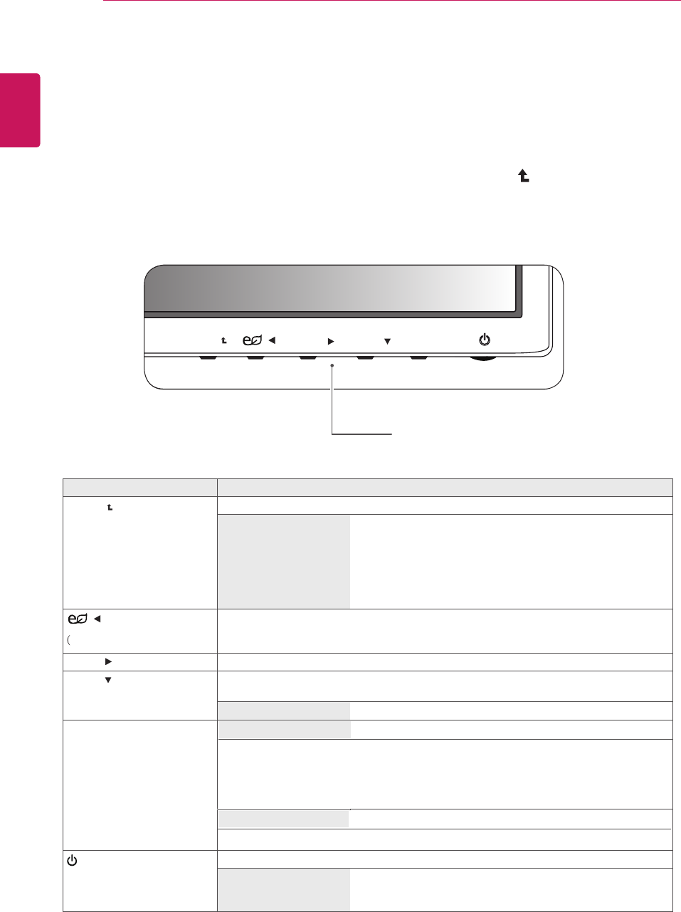
Press the desired button on the bottom of the Monitor set .
Change the value of the menu item by pressing the buttons on the bottom of the Monitor set.
To return to the upper menu or set other menu items, use the up arrow ( ) button.
Select EXIT to leave the OSD menu.
Monitor set Buttons
MENU / /INPUT / EXIT
MODE / AUTO /
12
ENG
ENGLISH
USING THE MONITOR SET
3
Button Description
Accesses the main menus.(See p.13)
OSD LOCKED/
UNLOCKED This function allows you to lock the current control settings, so
that they cannot be inadvertently changed.
Press and hold the MENU button for several seconds.
The message "OSD LOCKED" should appear.
You can unlock the OSD controls at any time by pushing
the MENU button for several seconds. The message "OSD
UNLOCKED" should appear.
Use this button to enter CUSTOM,TEXT,PHOTO,CINEMA,GAME menus.(See p.19)
When adjusting your display settings, always press the AUTO button on the MONITOR
SETUP OSD. (Only supported in Analog Mode)
The best display mode 1920 x 1080
INPUT / EXIT
You can choose the input signal.
• When two input signals are connected, you can select the input signal (D-SUB/DVI/
HDMI) you want.
• When only one signal is connected, it is automatically detected. The default setting is
D-SUB.
Exit the OSD(On Screen Display).
(Power Button) Turns the power on or off.
Power Indicator The power indicator stays red if the display is running
properly (On Mode). If the display is in Sleep Mode, the power
indicator blinks red.
SUPER ENERGY SAVING)
Use this button to enter SUPER ENERGY SAVING menu.For
more information.(See p.18)
/
MODE /
AUTO /
INPUT
EXIT
MENU /
Menu Settings
Each option is explained below.
yAnalog: D-SUB(Analog signal) input.
yDigital: DVI-D(Digital signal) input.
yHDMI: HDMI(Digital signal) input.
Customizing Settings MENU
EXIT
R
WIDE / ORIGINAL
RESET
CONTRAST
BRIGHTNESS
NO
NEXT MENU
1 / 2
1 / 2
WIDE
NEXT MENU PICTURE
MENU
>>
EXIT
1 / 2
5
BLACK LEVEL
SHARPNESS
HIGN
B
A
OVERSCAN OFF 1 / 2
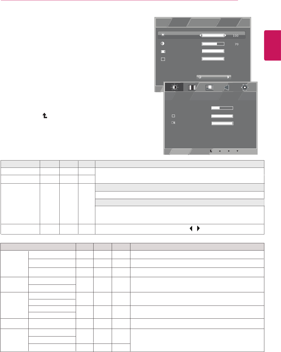
1
Select to leave the OSD menu.
To return to the upper menu or set other menu items, use
the up arrow ( ) button.
NEXT MENU
2 Settheoptionsbypressingthe◄or►or▼buttons.
3
Select the " " button to enter the more option
settings.
Press button on the bottom of the Monitor set to
display the MENU OSD.
MENU
13
ENG
ENGLISH
CUSTOMIZING SETTINGS
4 EXIT
Analog Digital Description
PICTURE ● ● To adjust the clearness of the screen .
COLOR ● ● To customize the color of the screen
GAMMA
COLOR TEMP
DISPLAY HORIZONTAL
VERTICAL ●To adjust the position of the screen
CLOCK
PHASE ●To improve the clarity and stability of the screen
OTHERS LANGUAGE
POWER INDICATOR ● ● To customize the screen status for a user's operating
environment
WHITE BALANCE ●
OVERSCAN
SHARPNESS
BLACK LEVEL
HDMI
●
●
●
To set offset level
VOLUME To adjust the volume
●
●
●
To improve the clarity and stability of the screen.
Menu Description
BRIGHTNESS
CONTRAST
WIDE/ORIGINAL
RESET
WIDE
Switch to full screen mode according to input image signal.
Change the input image signal ratio to original.
* This function works only if input resolution is lower than Monitor
set ratio (16:9).
ORIGINAL
Restore all factory default settings . Press the , buttons to reset immediately.
Analog Digital HDMI
● ● ●
● ● ●
● ● ●
● ● ●
MENU-->NEXT MENU
To adjust the brightness, contrast of the screen.