LG Electronics USA FB915B 19-inch Color Monitor with USB Hub User Manual
LG Electronics USA 19-inch Color Monitor with USB Hub Users Manual
UserManual.wiki
>
LG Electronics USA
>
FB915B User Manual
Users Manual
Navigation menu
Upload a User Manual
Namespaces
Wiki Guide
HTML
PDF
Info
Views
User Manual
Discussion / Help
Navigation

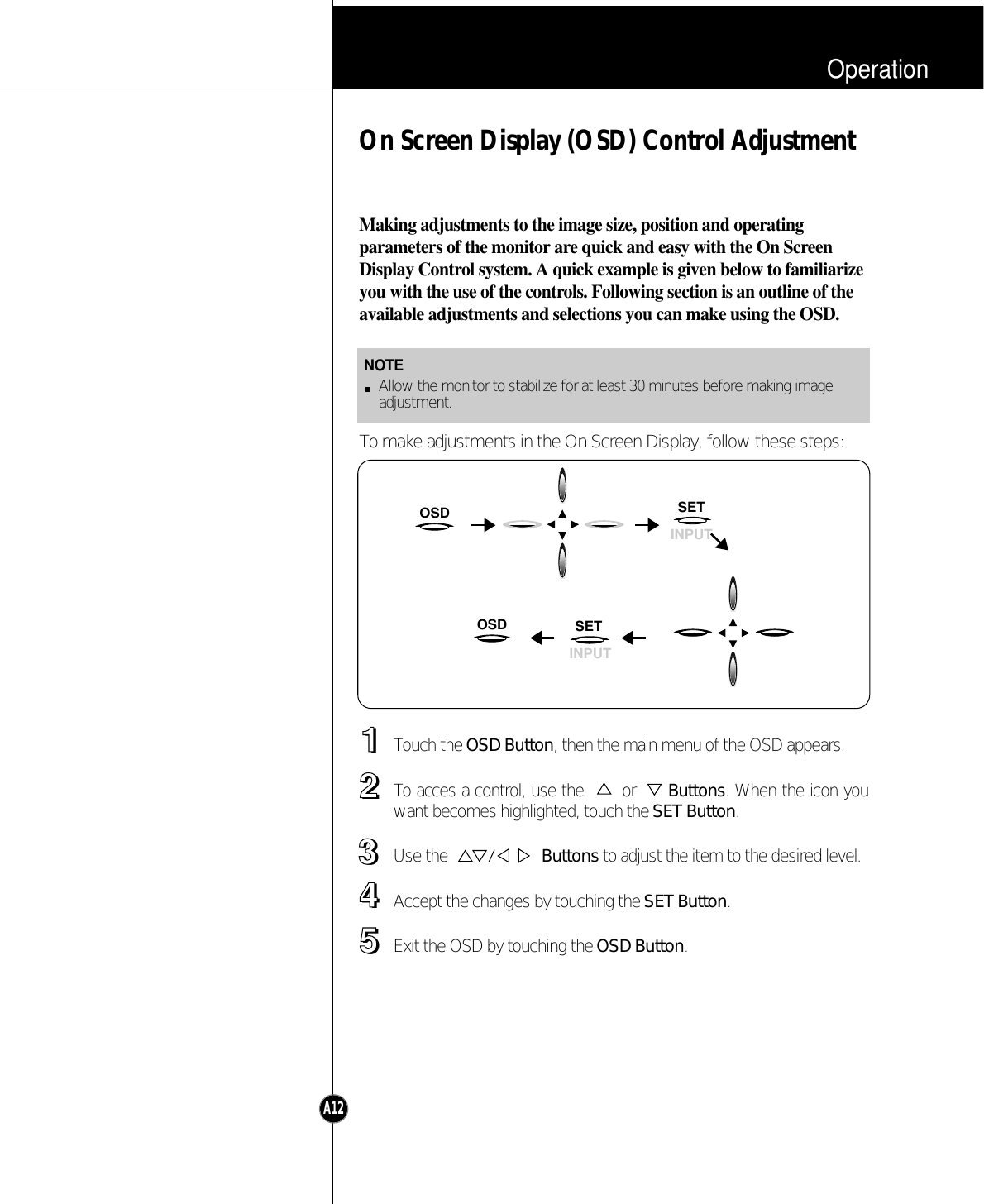
![OperationFront Panel ControlsA11Control Panel FunctionUse this button toenter or exit theon screen display.OSD ButtonUse this button toenter a selectionin the on screendisplay.SET ButtonUse these buttons tochoose or adjust itemsin the on screen display.ButtonsUse this button to selectvideo input (D-sub orBNC).INPUT ButtonUse this button to turnthe monitor on or off.Power ButtonThe power indicator light is shown inthe power button. This indicator lightsup green when the monitor operatesnormally. If the monitor is in DPM(Energy Saving) mode (stand-by/suspend/ off), this indicator colorchanges to amber.Power IndicatorOSD SETINPUT<Shortcut Keys>• To adjust brightness and contrastdirectly, press the button.You can also adjust the contrast andbrightness by selecting[BRIGHTNESS CONTRAST] fromthe OSD main menu.• To select video input (D-sub or BNC)directly, press the INPUT button.](https://usermanual.wiki/LG-Electronics-USA/FB915B/User-Guide-85478-Page-15.png)