LG Electronics USA GX2MP 20.1" LCD MONITOR User Manual EMISSION TEST REPORT
LG Electronics USA 20.1" LCD MONITOR EMISSION TEST REPORT
UserManual.wiki
>
LG Electronics USA
>
GX2MP User Manual
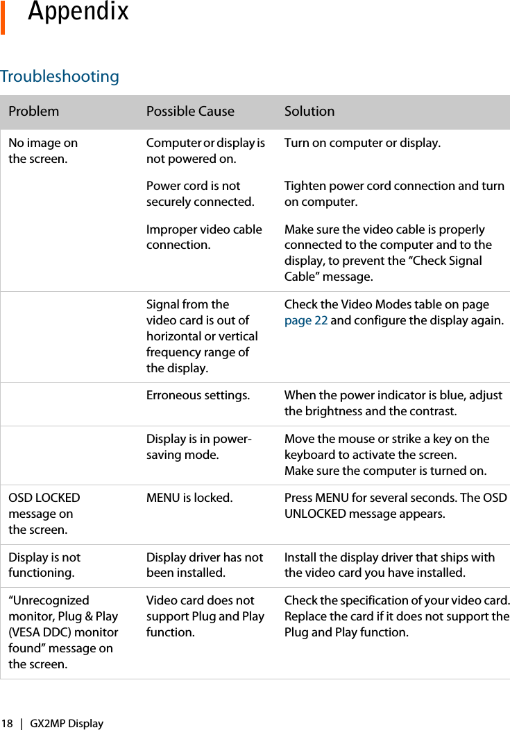
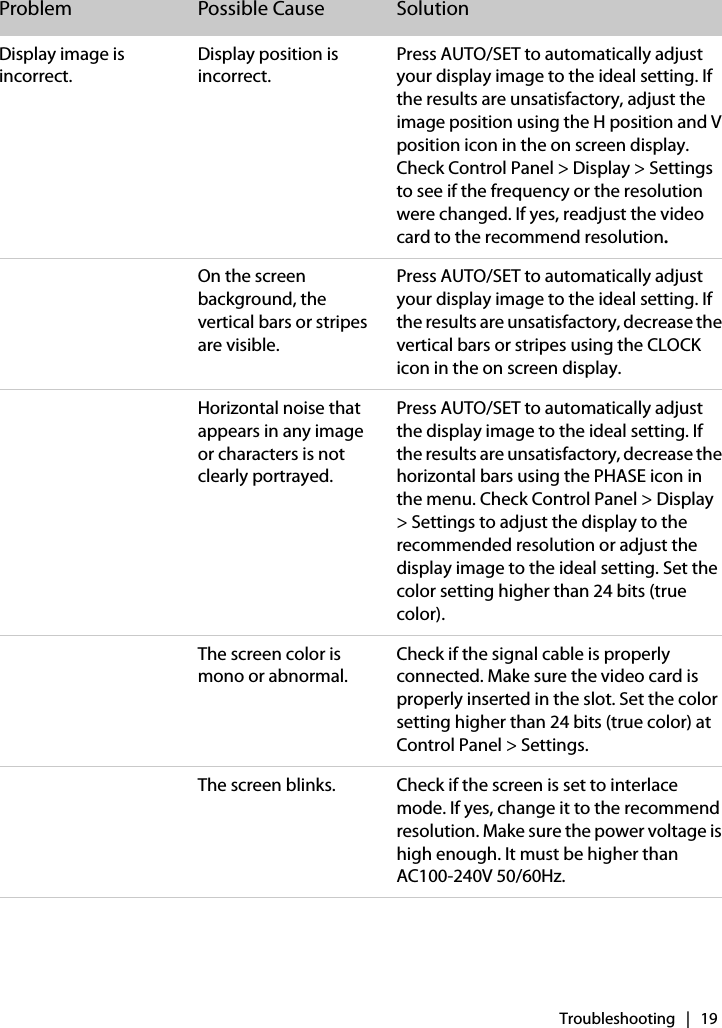
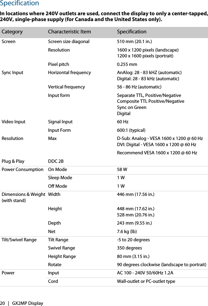
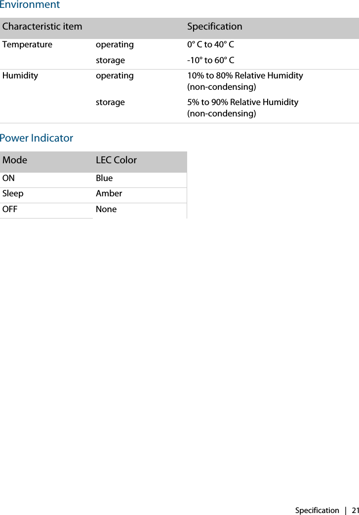
USERS MANUAL
Navigation menu
Upload a User Manual
Namespaces
Wiki Guide
HTML
PDF
Info
Views
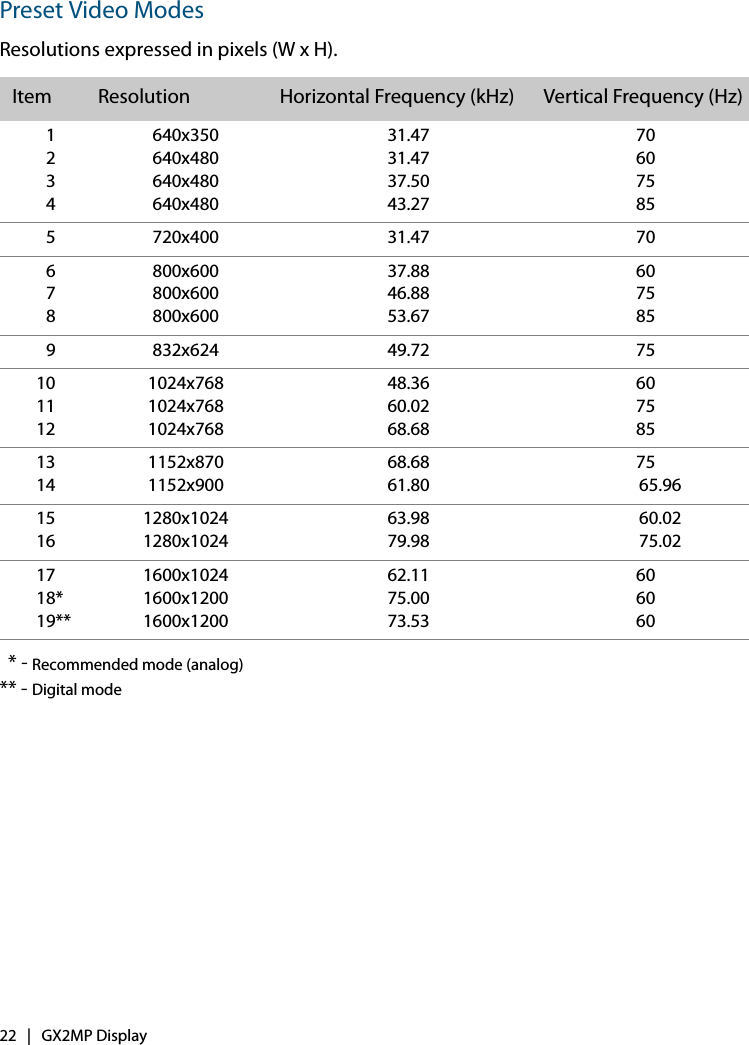
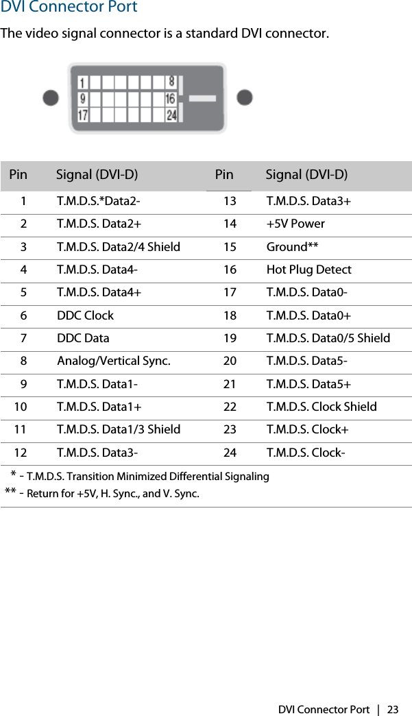
User Manual
Discussion / Help
Navigation