LG Electronics USA L1730SFN 17 inch LCD Monitor User Manual Microsoft PowerPoint F User s Manual
LG Electronics USA 17 inch LCD Monitor Microsoft PowerPoint F User s Manual
UserManual.wiki
>
LG Electronics USA
>
L1730SFN User Manual
Users Manual
Navigation menu
Upload a User Manual
Namespaces
Wiki Guide
HTML
PDF
Info
Views
User Manual
Discussion / Help
Navigation
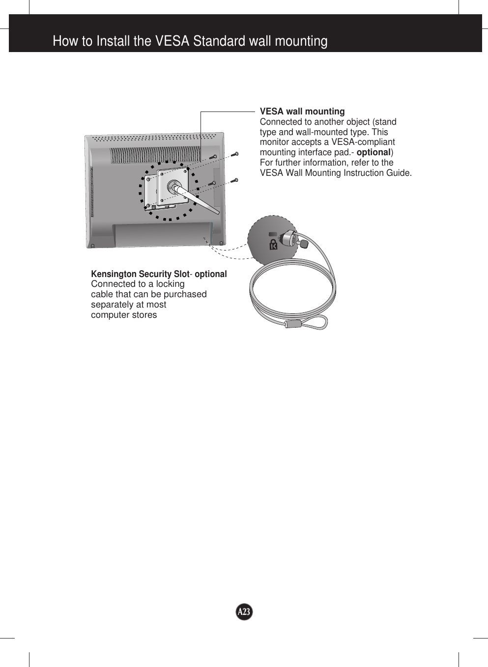
![A20Controlling the Multiple MonitorsCommand Reference List COMMAND1 COMMAND2 DATA(Hexa) 01. Power k a 0, 1 02. Contrast k g 0 - 6403. Brightness k h 0 - 6404. Color k u 0, 2Transmission[Command1][Command2][ ][Set ID][ ][Data][Cr]* [Command 1]: First command.* [Command 2]: Second command.* [Set ID]: You can adjust the set ID to choose desired monitorID number in Setup menu. Adjustment range is 0~ 99. When selecting Set ID ‘0’, every connectedmonitor set is controlled. Set ID is indicated as decimal(0~99) on menu and as Hexa decimal (0x0~0x63)on transmission/receiving protocol.* [DATA]: To transmit command data.Transmit 'FF' data to read status of command.* [Cr]: Carriage ReturnASCII code ‘0x0D’* [ ]: ASCII code Space (0x20)’OK Acknowledgement[Command2][ ][Set ID][ ][OK][Data][x]* The Monitor transmits ACK (acknowledgement) based onthis format when receiving normal data. At this time, if thedata is data read mode, it indicates present status data. Ifthe data is data write mode, it returns the data of the PCcomputer.Error Acknowledgement[Command2][ ][Set ID][ ][NG][Data][x]* The Monitor transmits ACK (acknowledgement) based onthis format when receiving abnormal data from non-viablefunctions or communication errors.Data 1: Illegal Code2: Not supported function3: Wait more timeTransmission / Receiving Protocol](https://usermanual.wiki/LG-Electronics-USA/L1730SFN/User-Guide-497855-Page-26.png)
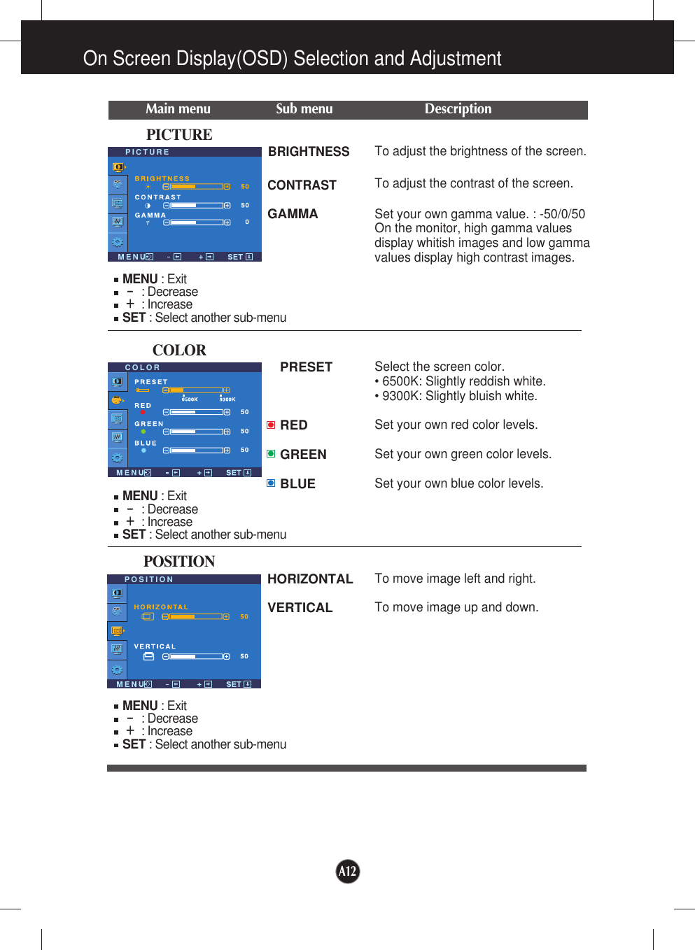
![Controlling the Multiple MonitorsA21Power On (Command:a)To control Power On/Off of the monitor.Transmission[k][a][ ][Set ID][ ][Data][Cr]Data 0 : Power Off 1 : Power OnAcknowledgement[a][ ][Set ID][ ][OK][Data][x]To show Power On/Off.Transmission[k][a][ ][Set ID][ ][FF][Cr]Data 0 : Power Off 1 : Power OnAcknowledgement[a][ ][Set ID][ ][OK][Data][x]Transmission / Receiving ProtocolContrast (Command:g)To adjust screen contrast.You can also adjust contrast in the Contrast/Brightness menu.Transmission[k][g][ ][Set ID][ ][Data][Cr]Data Min : 0 ~ Max : 64Refer to ‘Real data mapping’ as shown below.Acknowledgement[g][ ][Set ID][ ][OK][Data][x]* Real data mapping0 : Step 0A : Step 10 (SET ID 10)F : Step 15 (SET ID 15)10 : Step 16 (SET ID 16)64 : Step 100](https://usermanual.wiki/LG-Electronics-USA/L1730SFN/User-Guide-497855-Page-27.png)
![A22Controlling the Multiple MonitorsTransmission / Receiving ProtocolBrightness (Command:h)To adjust screen brightness.You can also adjust brightness in the Contrast/Brightness menu.Transmission[k][h][ ][Set ID][ ][Data][Cr]Data Min : 0 ~ Max : 64Refer to ‘Real data mapping’ as shown below. Acknowledgement[h][ ][Set ID][ ][OK][Data][x]* Real data mapping 0 : Step 0A : Step 10 (SET ID 10)F : Step 15 (SET ID 15)10 : Step 16 (SET ID 16)64 : Step 100Color (Command:U)To adjust the screen color.You can also adjust color in the Color adjustment menu.Transmission[k][u][ ][Set ID][ ][Data][Cr]Data 0 : 9300K2 : 6500KAcknowledgement[u][ ][Set ID][ ][OK][Data][x]Transmission / Receiving Protocol](https://usermanual.wiki/LG-Electronics-USA/L1730SFN/User-Guide-497855-Page-28.png)