LG Electronics USA L1780UN 17" LCD Monitor User Manual Microsoft PowerPoint F User s Manual
LG Electronics USA 17" LCD Monitor Microsoft PowerPoint F User s Manual
UserManual.wiki
>
LG Electronics USA
>
L1780UN User Manual
>
users manual
Contents
1.
users manual
2.
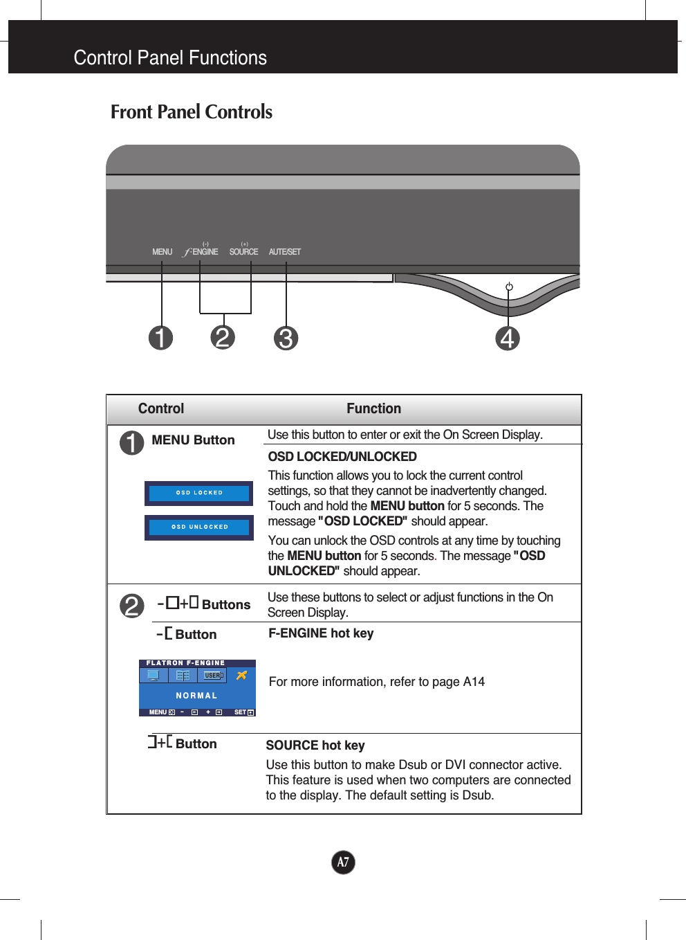
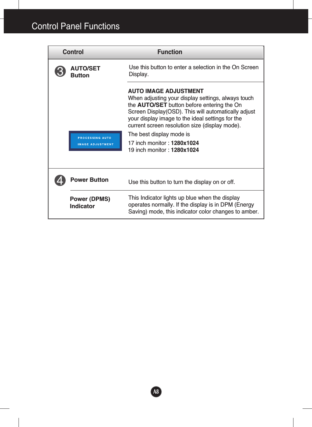
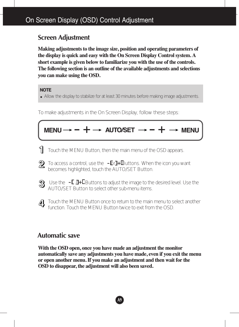
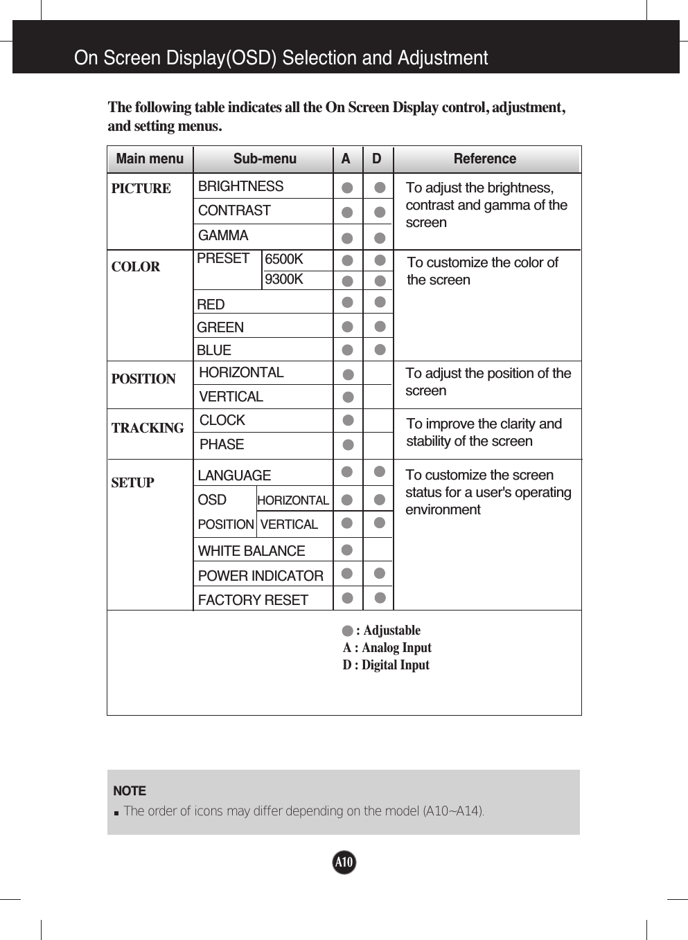
USERS MANUAL
users manual
Navigation menu
Upload a User Manual
Namespaces
Wiki Guide
HTML
PDF
Info
Views
User Manual
Discussion / Help
Navigation