LG Electronics USA L20NU 20" LCD MONITOR User Manual User s Manual H
LG Electronics USA 20" LCD MONITOR User s Manual H
UserManual.wiki
>
LG Electronics USA
>
L20NU User Manual
USERS MANUAL
Navigation menu
Upload a User Manual
Namespaces
Wiki Guide
HTML
PDF
Info
Views
User Manual
Discussion / Help
Navigation
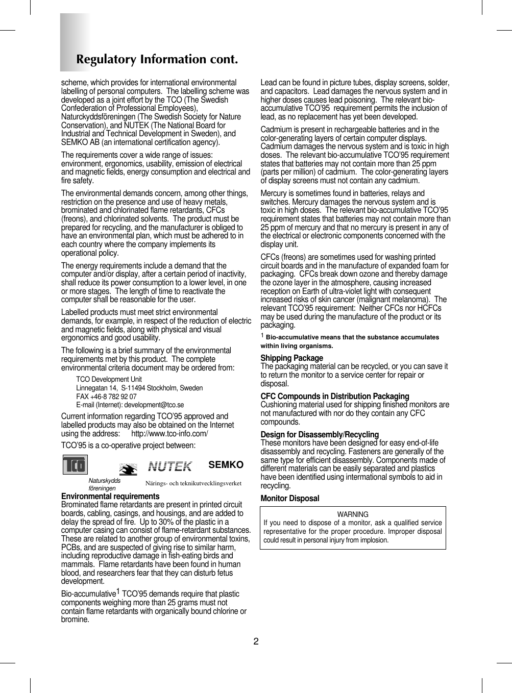
![Connecting the DisplayA3Before setting up the monitor, ensure that the power to the monitor, thecomputer system, and other attached devices is turned off. Positioning your display1. Adjust the position of the panel in various ways for maximum comfort.Tilt Range : -5˚~30˚ Swivel : 90˚ErgonomicIt is recommended that in order to maintain an ergonomic and comfortable viewingposition, the forward tilt angle of the monitor should not exceed 5 degrees.Height Range : maximun 3.15 inch (80.0mm)Landscape & Portrait : You can rotate the panel 90o clockwise. (* For detailed information, please refer to the Pivot Sofeware CD provided.)* Make sure not to touch thefloor when the head rotatesto use the Pivot function.80.0mmUnfasten the [Stand lock]clockwise to adjust theheight of the stand.](https://usermanual.wiki/LG-Electronics-USA/L20NU/User-Guide-544214-Page-8.png)