LG Electronics USA L226WTQS 22" LCD MONITOR User Manual L206WD ENG
LG Electronics USA 22" LCD MONITOR L206WD ENG
UserManual.wiki
>
LG Electronics USA
>
L226WTQS User Manual
>
User Manual
Contents
1.
USERS MANUAL
2.
User Manual
User Manual
Navigation menu
Upload a User Manual
Namespaces
Wiki Guide
HTML
PDF
Info
Views
User Manual
Discussion / Help
Navigation
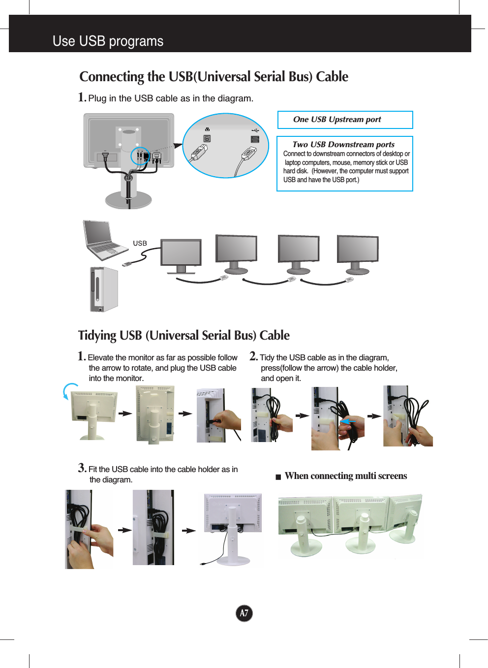
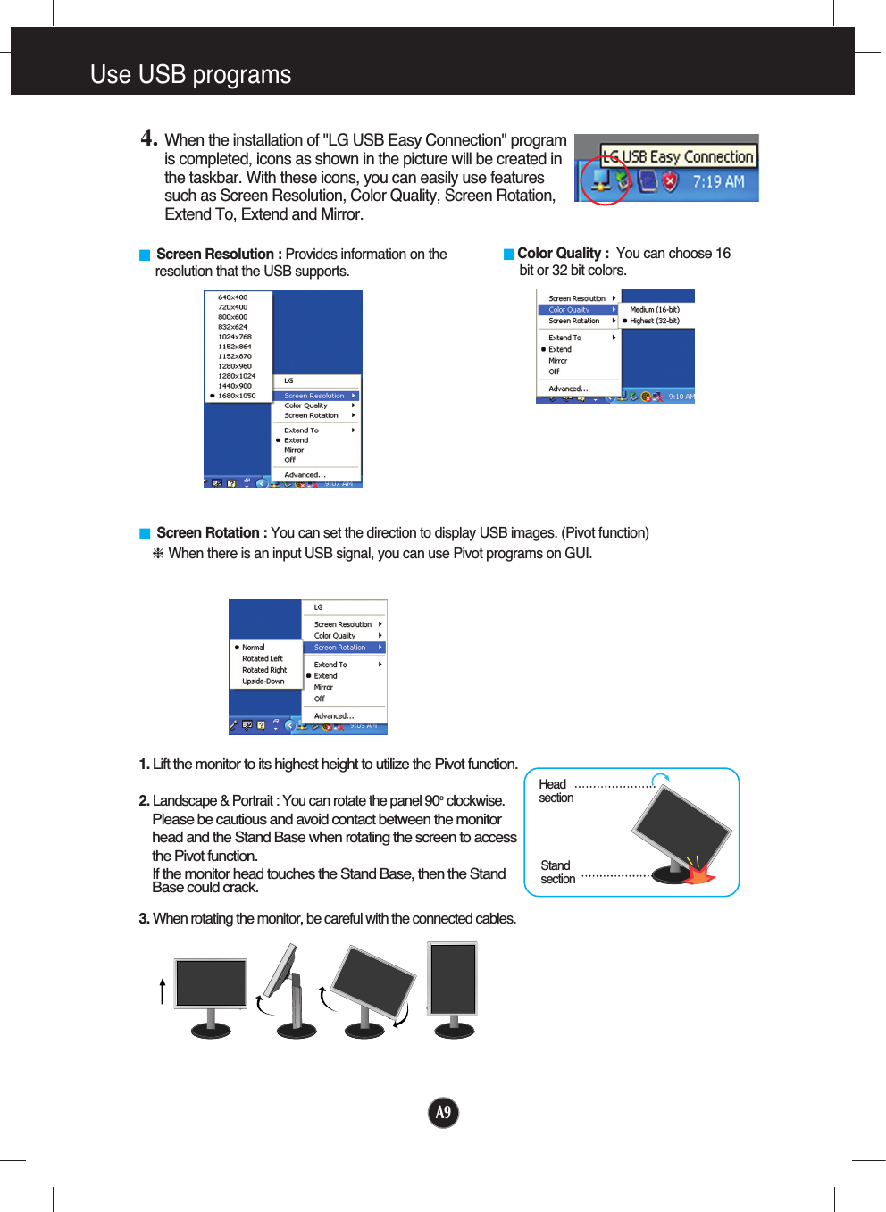
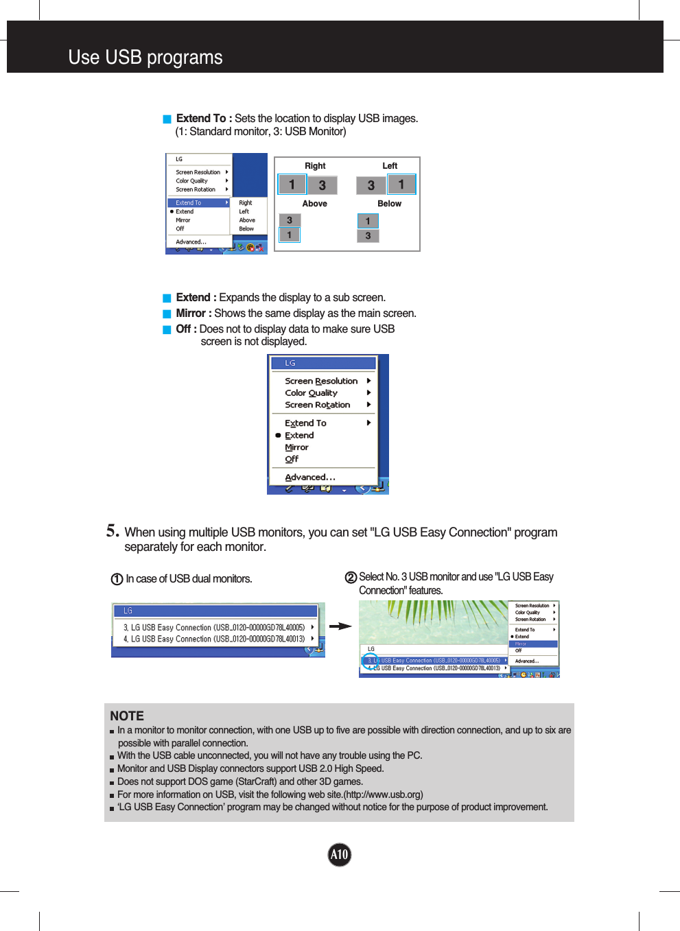
![A8Use USB programs The display feature can be used by easily connecting the USB cable betweenlaptops/desktops and the USB port at the back of the monitor. System RequirementsIn order to make full use of USB Display features, your computer must meet the following minimumsystem requirements: •1.2 GHz CPU or higher, 512 MB memory or higher (Recommended Specifications: 1.6 GHz Core2 Duo CPU, 1 GB memory) •USB 2.0 Interface •Windows 2000 (Service Pack 4), Windows XP (Service Pack 2) Operating Systems (O/S) are supported. (But, Windows 98, ME, NT, Vista, Macintosh, Linux Operating Systems (O/S) are not supported.) 1. Connect the USB cable as shown in the picture and press the 'SOURCE' button on the front of themonitor to select the main display. 2. “LG USB Easy Connection” driver installation automatically starts. Before installation, make sure your computer meets the minimum system requirements of Windows2000 (Service Pack 4) and Windows XP (Service Pack 2). If your computer fails to meet thoserequirements, update the operating systems at http://www.microsoft.com. When the “LG USB Easy Connection” program does not install automatically, please install the drivermanually as shown below. Use USB programs 123456If your computer fails to meet the system requirements, the warning message "DisplayLink Core Software" will be displayed. Press the [OK] button, and continue to install "LG USB Easy Connection" program. 3. Install "LG USB Easy Connection" program as the instruction message says, fully remove the USB cable,and then reboot your computer. Without rebooting, "LG USB Easy Connection" will not operate properly.For more detailed information on installation and removal, refer to the accompanied <LG USB EasyConnection Installation Guide>.](https://usermanual.wiki/LG-Electronics-USA/L226WTQS.User-Manual/User-Guide-909991-Page-10.png)