LG Electronics USA L227WTS LCD Monitor User Manual L226WT ENG
LG Electronics USA LCD Monitor L226WT ENG
UserManual.wiki
>
LG Electronics USA
>
L227WTS User Manual
users manual
Navigation menu
Upload a User Manual
Namespaces
Wiki Guide
HTML
PDF
Info
Views
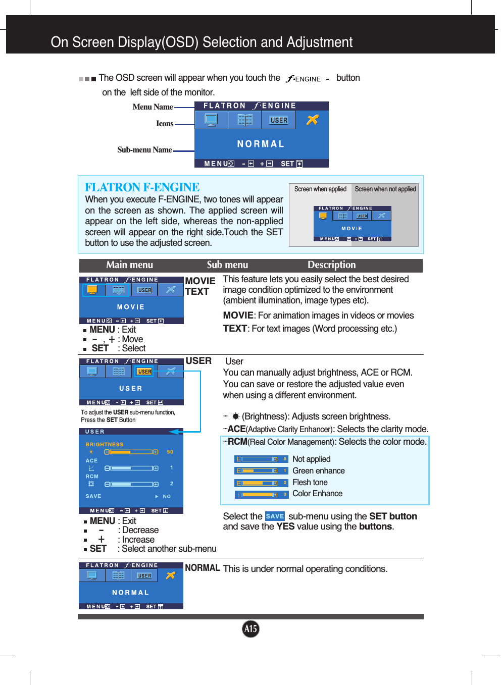
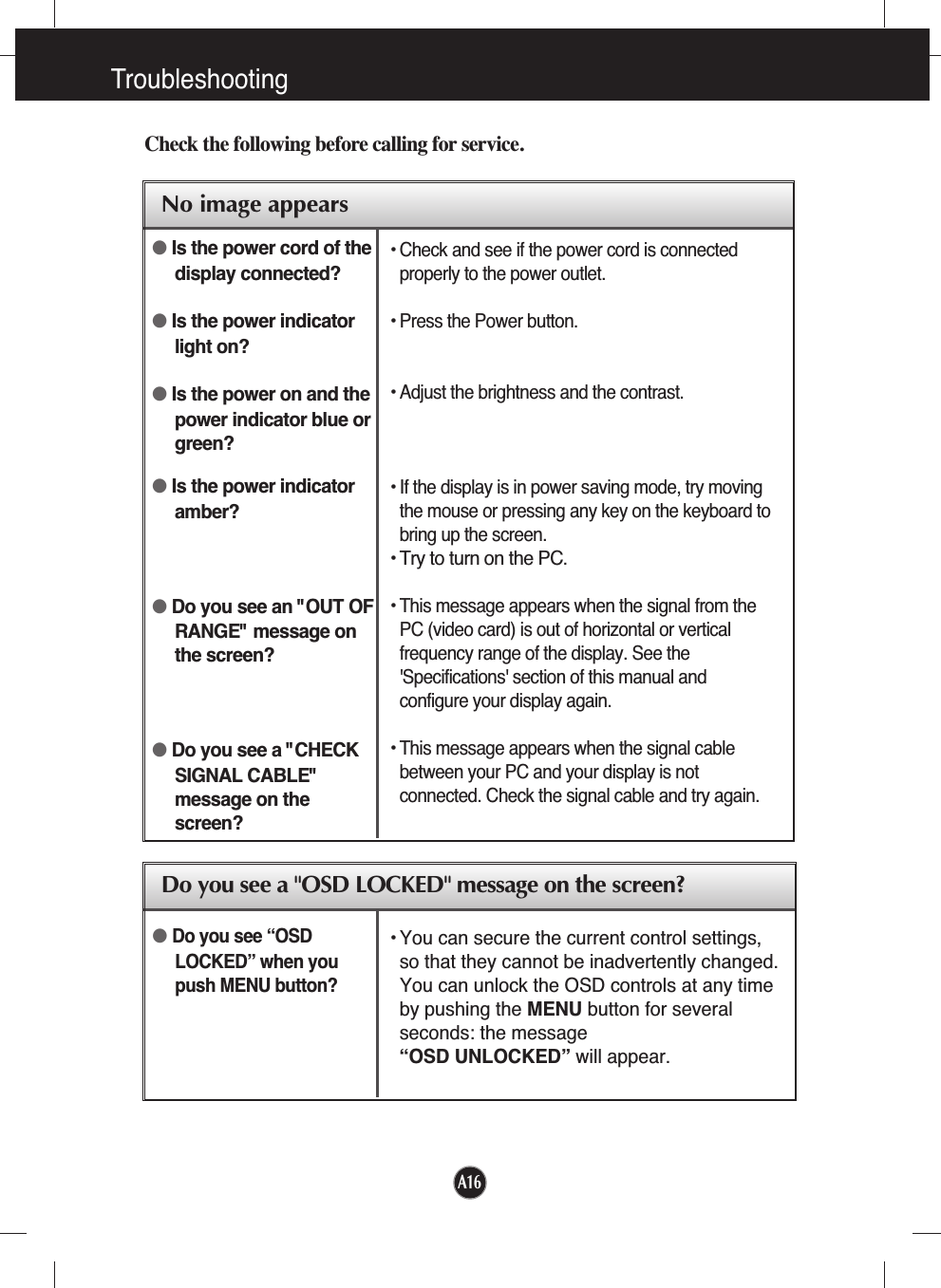
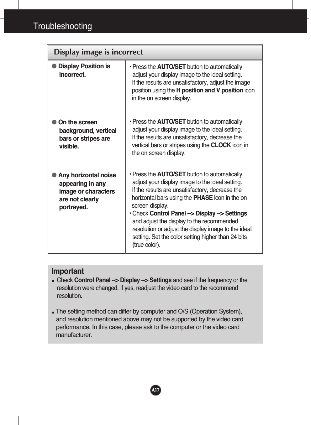
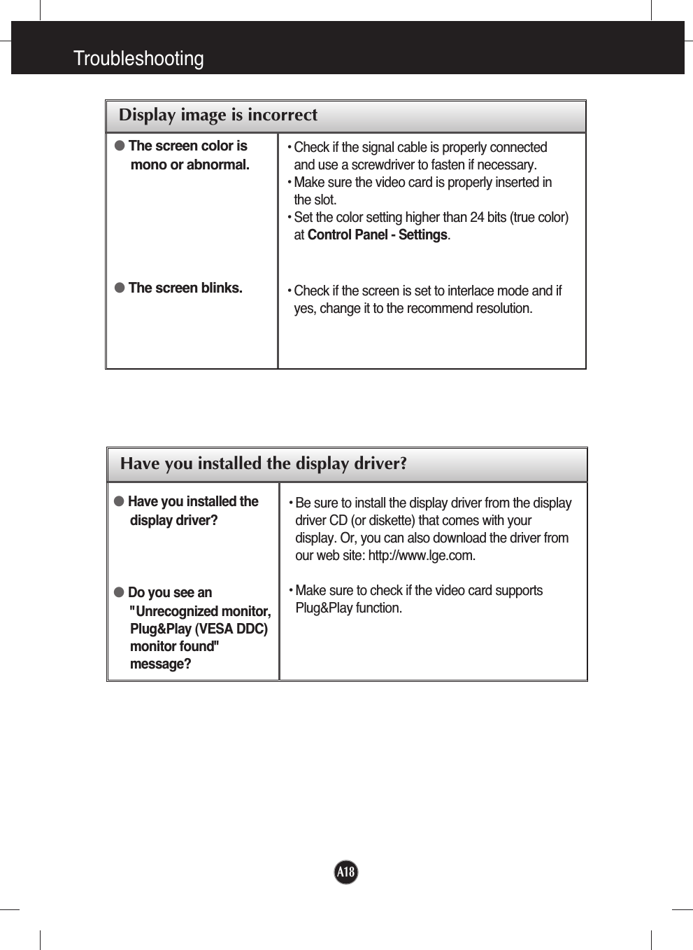
User Manual
Discussion / Help
Navigation