LG Electronics USA LST255 CDMA Fixed Wireless Terminal User Manual LST 255 M
LG Electronics USA CDMA Fixed Wireless Terminal LST 255 M
User Manual
Model: LST-255(F)
Please read this manual carefully before operating
your set. Retain it for future reference.
CDMA Fixed Wireless Terminal
User Guide

LGE CDMA Fixed Wireless Terminal LST-255(F)
3
DATE ISSUE CONTENTS OF CHANGES REMARK
2004.10 1.0 Initial Release
REVISED HISTORY
●Please read this manual before you use this product. This manual is
based on the production version of LST-255(F) FWT. Software
changes may have occurred after this printing.
●LGE reserves the right to make changes in technical and product
specifications without prior notice.

Table of Contents
5
1Before You Start 7
Safety Information 7
Optimal Phone Performance 7
Care and Service 8
Safety Information 9
2Introduction 12
Component List 13
Front, Side and Rear View of the Terminal 14
3 LEDs Indicators 16
Installation 17
Installation Steps 20
3Basic Operation 21
Power On 21
Placing a call 21
Receiving a call 22
Ending a call 22
Warning Tone after Remote Disconnect 22
Emergency Call 22
Power Off 23
4System Features 24
Hook flash 24
ROH (Receiver Off Hook) 24
System Features 24
Applications 26
Before You Start
9
ƅDo not use harsh chemicals, cleaning solvents, or
strong detergents to clean it. Wipe it with a soft cloth
that has been slightly dampened in a mild soap-and
water solution.
ƅDo not paint it. Paint can clog the device’s moving
parts and prevent proper operation.
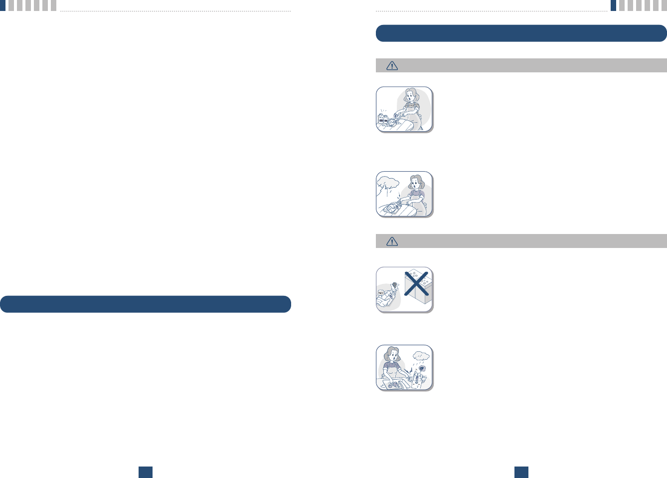
ƅDuring lightning, do not touch power plug or phone
line. It may cause an electric shock or death.
ƅDo not use with car battery. It may cause an electric
shock, fire, breakdown or transformation.
ƅFor safety use, use only adapter approved by LG.
To all problems arising from not following this guide,
LG does not bear responsibility.
ƅAvoid exposure to high temperature or humidity.
Avoid wetting the unit with any liquids. If the unit gets
wet, turn the power off immediately and remove the
backup battery and AC power supply.
ƅKeep it dry. Precipitation, humidity, and liquids con-
tain minerals that may corrode electronic circuits.
Safety Information
Before You Start
8
- Connect the equipment into an outlet on a circuit different from that to
which the terminal is connected.
- Consult you Authorized LGE Dealer of an experienced radio/TV techni-
cian for help.
ƅUse only the battery, antenna and AC power supply provided by LGE.
Using any other type will invalidate the warranty.
ƅOnly authorized personnel should service the phone and its accessories.
Faulty installation or service can be dangerous and may invalidate the war-
ranty.
ƅDo not use the unit in designated Ŕno cellular phone useŕarea.
Avoid exposure to high temperature or humidity.
ƅAvoid wetting the unit with any liquids. If the unit gets wet, turn the power
off immediately and remove the backup battery and AC power supply. If
the unit is inoperable, then return to the service agent for service.
ƅAvoid shock or impact.
ƅWe recommend you to charge the backup battery before initial use. Backup
battery may be discharged during delivery.
ƅThis device complies with part 15 of the FCC Rules.
Operation is subject to the following two conditions:
- This device may not cause harmful interference, and
- This device must accept any interference received, including interference
that may cause undesired operation.
Care and Service
ƅUnplug the telephone from the wall outlet and remove antenna (or discon-
nect antenna cable) before cleaning. Do not use liquid or aerosol cleaners.
Use a damp cloth for cleaning.
ƅIf the unit fails for any reason, do not attempt to disassemble; contact the
telephone service provider for assistance.
ƅIf any of the following conditions exist: unplug the unit at the wall plug,
remove battery, and call the service provider.
- The power supply cord is damaged or frayed.
- Liquid has been spilled into the unit.
- The unit has been exposed to rain or water.
- The unit has been dropped or damaged.
- The unit does not work normally by following the operating instructions.
WARNING
CAUTION
Before You Start
11
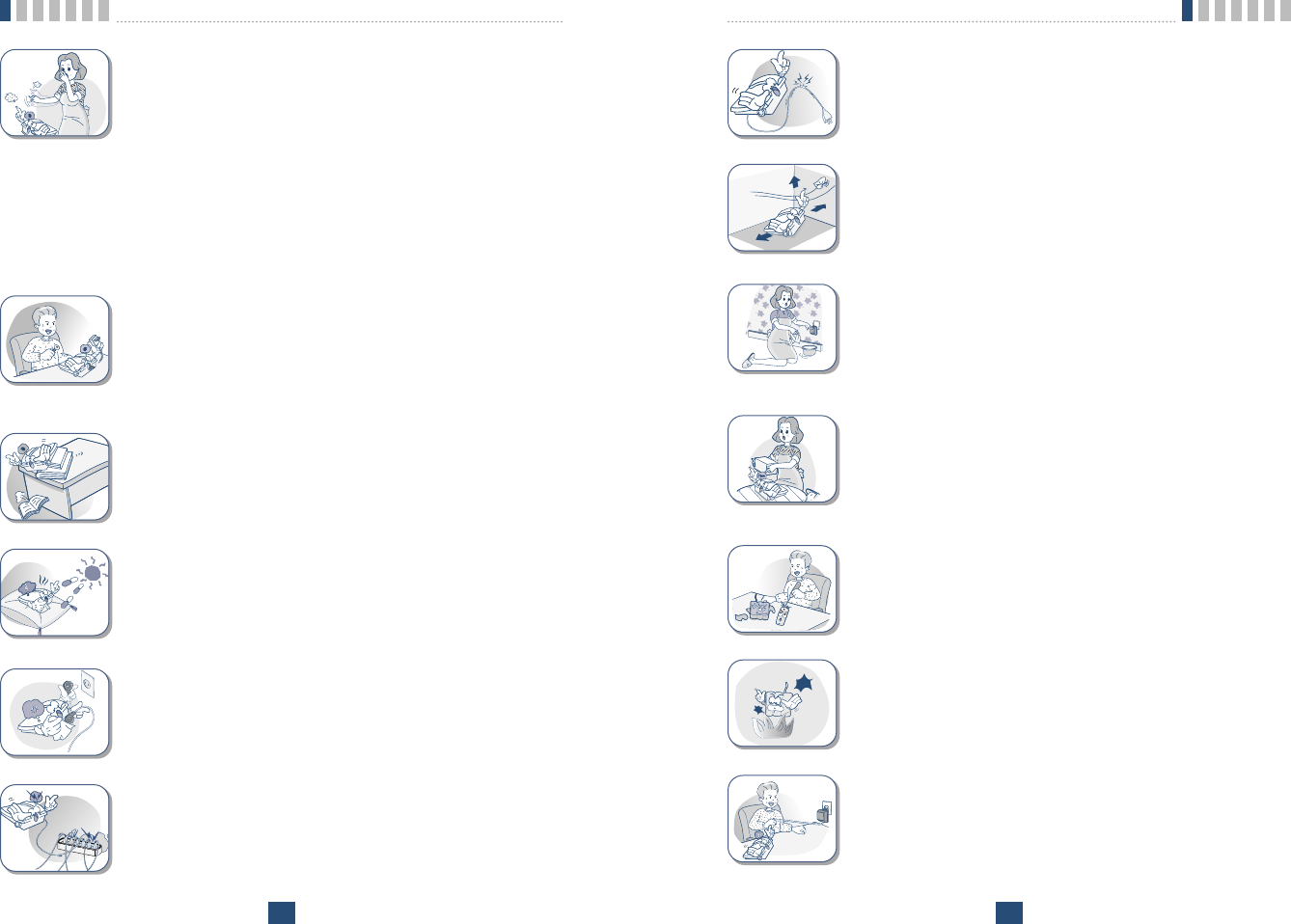
ƅDo not remodel the power cord or disassemble. If
power cord or plug is impaired, do not use it. It may
cause fire or electric shock.
ƅDo not install in an ill-ventilated place. It may be a
cause of fire or breakdown.
ƅDo not touch the plug with wet hands. When discon-
necting the power cord of any accessory, grasp and
pull the plug, not the cord. It may be a cause of fire
or electric shock.
ƅDo not put heavy things on the power cord. Do not
bend power cord too much. It may be a cause of fire
or electric shock.
ƅDo not short-circuit. It may start a fire or may
explode causing injury.
ƅDo not throw and impact battery. Do not dispose of
batteries by putting them in fire. It may explode or
catch fire by electrolyte.
ƅWhen you disconnect the power cord of any acces-
sory, grasp and pull the plug, not the cord. It may
cause an adapter breakdown.
Before You Start
10
ƅDo not use or store it in dusty, dirty areas as its
moving parts can be damaged.
ƅDo not store it in hot areas. High temperatures can
shorten the life of electronic devices, damage batter-
ies, and warp or melt certain plastics.
ƅDo not store it in cold areas. When the phone warms
up to its normal operating temperature, moisture can
form inside the phone, which could damage the
phone’s electronic circuit boards.
ƅDo not attempt to open it. Non-expert handling of the
device could damage it. Consult your authorized LG
dealer for help. It may cause be a cause of fire,
electric shock and breakdown.
ƅDo not drop, knock or shake it. Rough handling can
break internal circuit boards.
ƅDo not install under direct sunlight or on an uneven
surface.
ƅBefore using plug, check with available power volt-
age. Inaccurate power voltage may be a cause of
fire.
ƅDo not plug many power cords in outlet. It may
cause fire or electric shock.
Introduction
13
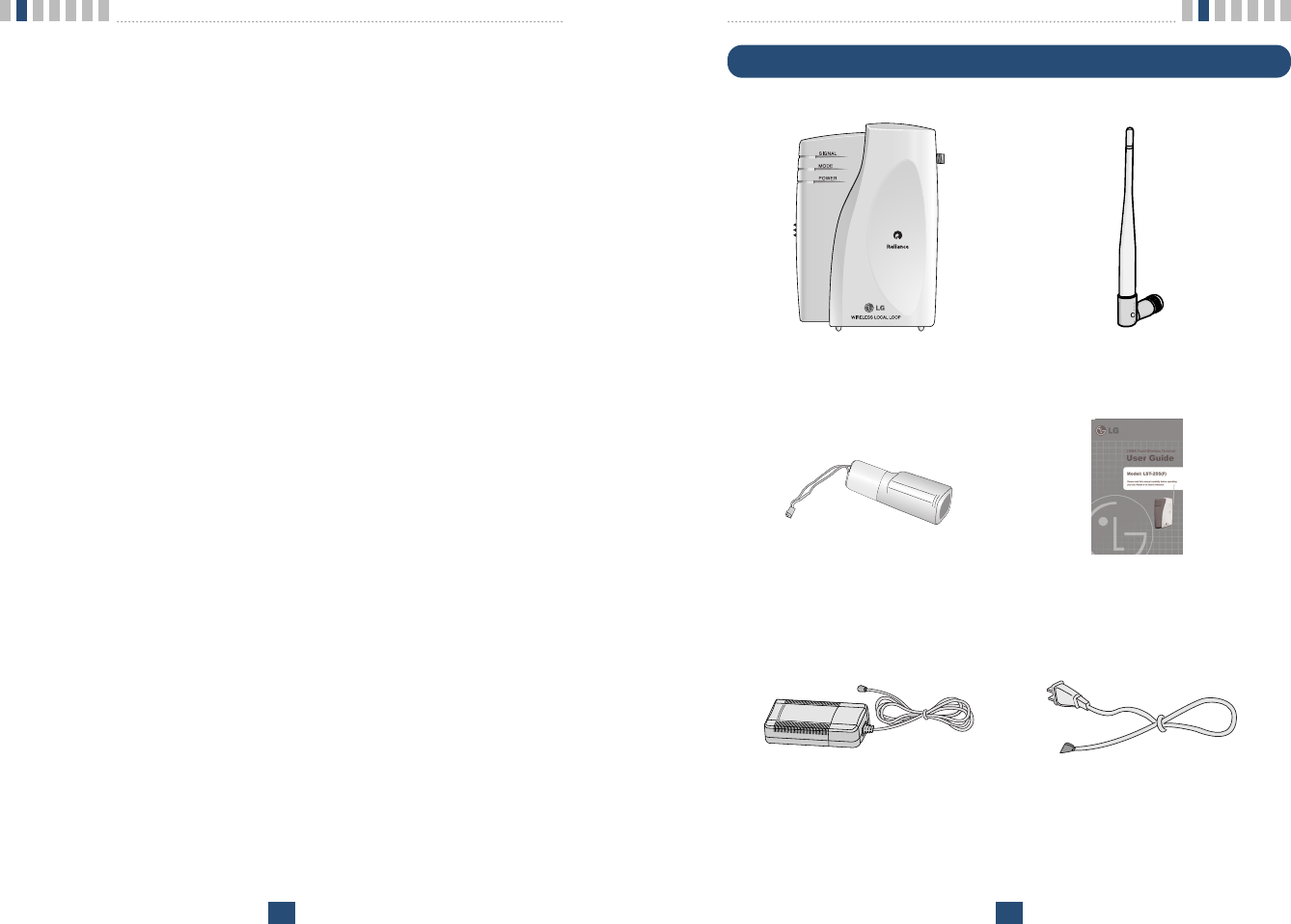
Component List
Introduction
12
Congratulations on your purchase of the LG Fixed Wireless Terminal that has
been designed to operate on the latest digital mobile communications technolo-
gy, Code Division Multiple Access (CDMA). This CDMA digital technology
has greatly enhanced voice clarity and can provide various advanced features.
The terminal enables the normal operation and direct connection of standard
telephone equipment into the cellular network.
The standard unit provides:
ƅA phone jack to plug in the telephone equipment(RJ-11 Port)
ƅRing voltage used to ring the telephone connected to the unit, with a Ringer
Equivalence Number of 4
ƅA phone jack to plug in the G3 FAX equipment (RJ-11 Port)
ƅData Port for service and repair(RJ-45 Port or USB Port)
ƅAC Power supply with barrel plug connector
ƅSupport Dial tone
ƅTouch tone(DTMF) or Pulse Dialing
ƅSupport Caller ID Telephone
ƅVoice-Mail Notification ring alerts you to new voice-mail messages
ƅThree lights (LEDs) to indicate the status of the unit
ƅDipole Antenna
Some features can not be supported by service providerœs equipment status.
For instance, the following features may not be supported:
ƅSpeed Dial
ƅEmergency Call
ƅHot Line Call
ƅAlarm
ƅOutgoing Call Lock
ƅQuick Dial Option with Œ#œ
Other features as determined by your service provider.
Note:
-Telephones with multiple terminating impedance should be set for 600ohms.
< Terminal > < Dipole Antenna >
< AC/DC Power Adapter > < Power Cord(only SMPS Adapter) >
< Backup Battery(Built-in) > < User Guide >
Introduction
15
Introduction
14
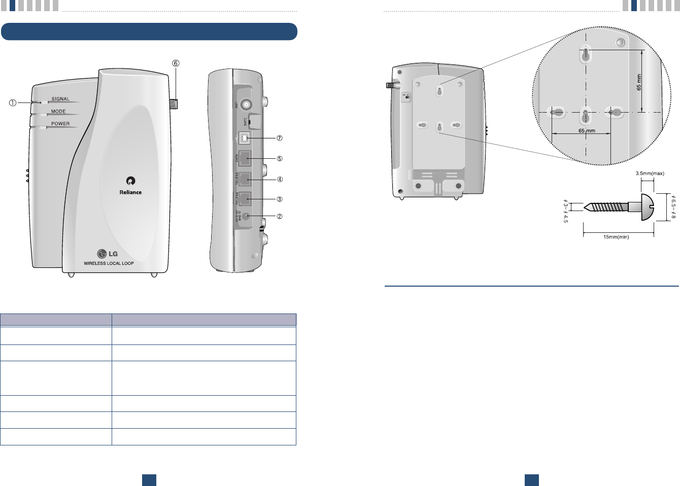
Installation for Wall Mounting.
ƅTo mount terminal on the wall, please follow the procedure to install it cor-
rectly.
1. Determine suitable location to mount terminal with mounting template.
2. Mark the two openings and select round or pan-head type screw.
3. Drill out the holes with drill bit smaller in diameter than the screws.
4. Secure two screws into the wall, leaving about 65mm gap between the
screw heads.
5. Insert the DC power jack into an electrical outlet and attach the tele-
phone line into the Phone Jack (RJ-11) of the terminal.
6. Place the terminal over the two screws.
7. Slide the terminal downward until the screw head is locked at the top
of the opening and the terminal is secure.
8. Check that set is fixed on the screws.
< Mounting Template >
Front, Side and Rear View of the Terminal
< Figure 1 >
ITEM DESCRIPTION
ڡLEDs Indicate the status of the unit
ڢDC IN 12V AC/DC Power Adapter
ڣ, ڤTEL (RJ-11 Port) Connecting Ports for SLT
(Single Line Telephone)
ڥDATA Port (RJ-45 Port) Connecting Port for Data Service to PC(RS-232C)
ڦAntenna Connector Connecting Port for TNC Antenna
ڧUSB Port Connecting Port for Data Service to PC(USB)
Introduction
17
Introduction
16
Installation
You should follow each step carefully as shown below in order to guarantee
proper operation of CDMA Fixed Wireless Telephone.
STEP I. Check Components
ƅFixed Wireless Terminal is supplied with the following standard unit and
accessories:
1. LST-255(F) Unit -1EA-
2. Dipole Antenna -1EA-
3. Backup Battery(Built-in) -1EA-
4. User Guide -1EA-
5. AC/DC Power Adapter -1EA-
6. Power Cord(Only SMPS Adapter) -1EA-
ƅPlease make sure that these components are present and check for evidence
of shipping before you begin the unit installation.
ƅIf components are missing or damage is found, contact your authorized LG
distributor immediately.
STEP II. Place the Terminal
ƅPlace the terminal on the stable flat secure surface area (desk, table, etc.).
Avoid direct exposure to the sunlight and damp areas.
ƅRead the SAFETY INFORMATION located at the first part of this docu-
ment before you place the terminal.
STEP III. Connect Components
ƅConnect the Dipole antenna to the TNC connector located at the topside of
the terminal. (See Figure 1 to locate the TNC connector.)
If you have placed the terminal on the flat surface, position the antenna up
side.
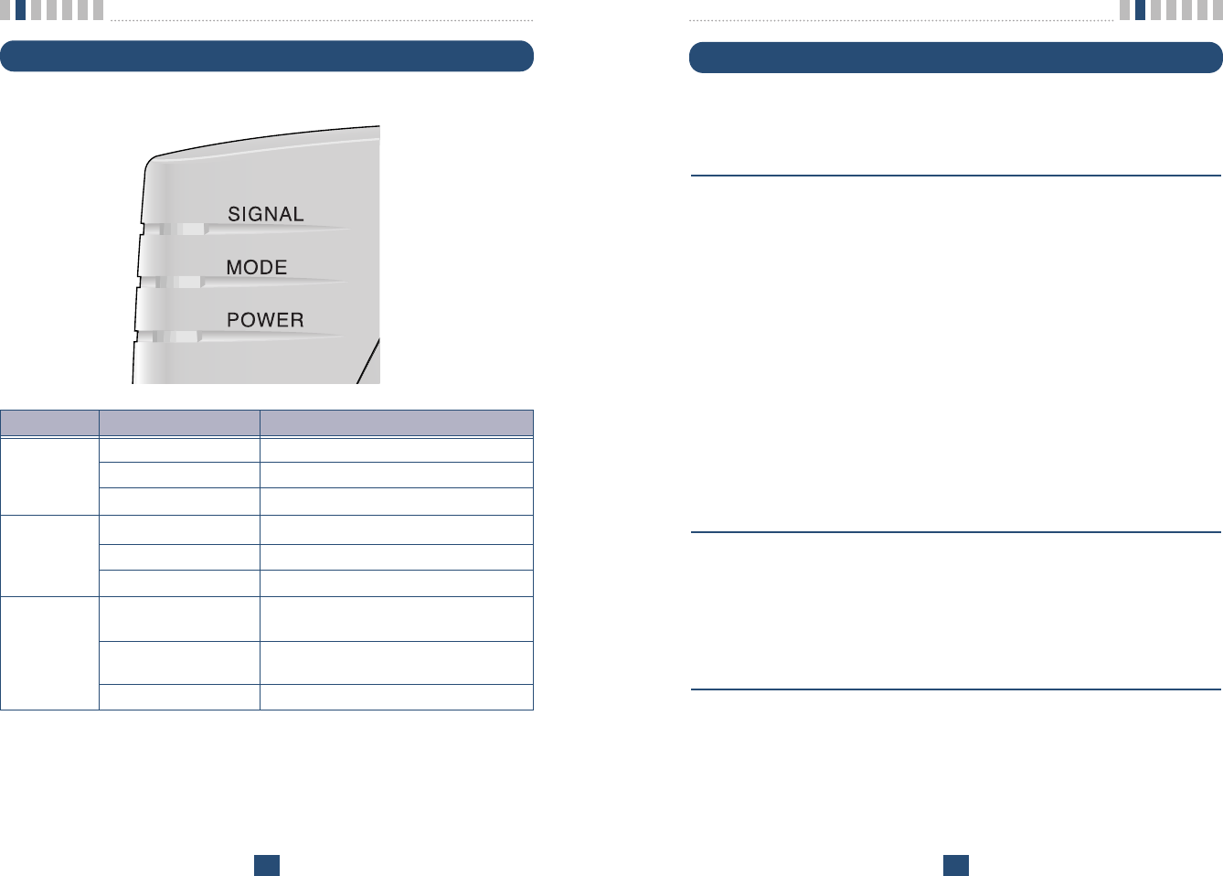
3 LEDs Indicators
< Table 1 >
LED COLOR Operating Condition
GREEN-solid DC Power is applied
POWER LED ORANGE-solid Battery Power is applied
RED-solid Low Battery
GREEN-solid Good Signal
SIGNAL LED ORANGE-solid Poor Signal
RED-solid No Service Area
GREEN - blink Voice Message is received
(0.5sec On / 0.5sec Off)
MODE LED GREEN - blink Data Service or G3 Fax Service is working
(1 sec On / 1 sec Off)
GREEN - solid G3 FAX receive mode is enabled
Introduction
19
Introduction
18
Note:
- G3 FAX can not be connected to your LST-255 terminal.
- Length between LST-255(F) and Telephone : over 1m.
- In communicating data, RS-232C and USB shouldnœt be used at the same time.
żThe adapter type(with power cord) may be different from country to
country.
! Connection telephone jack to data port will cause malfunction of data service
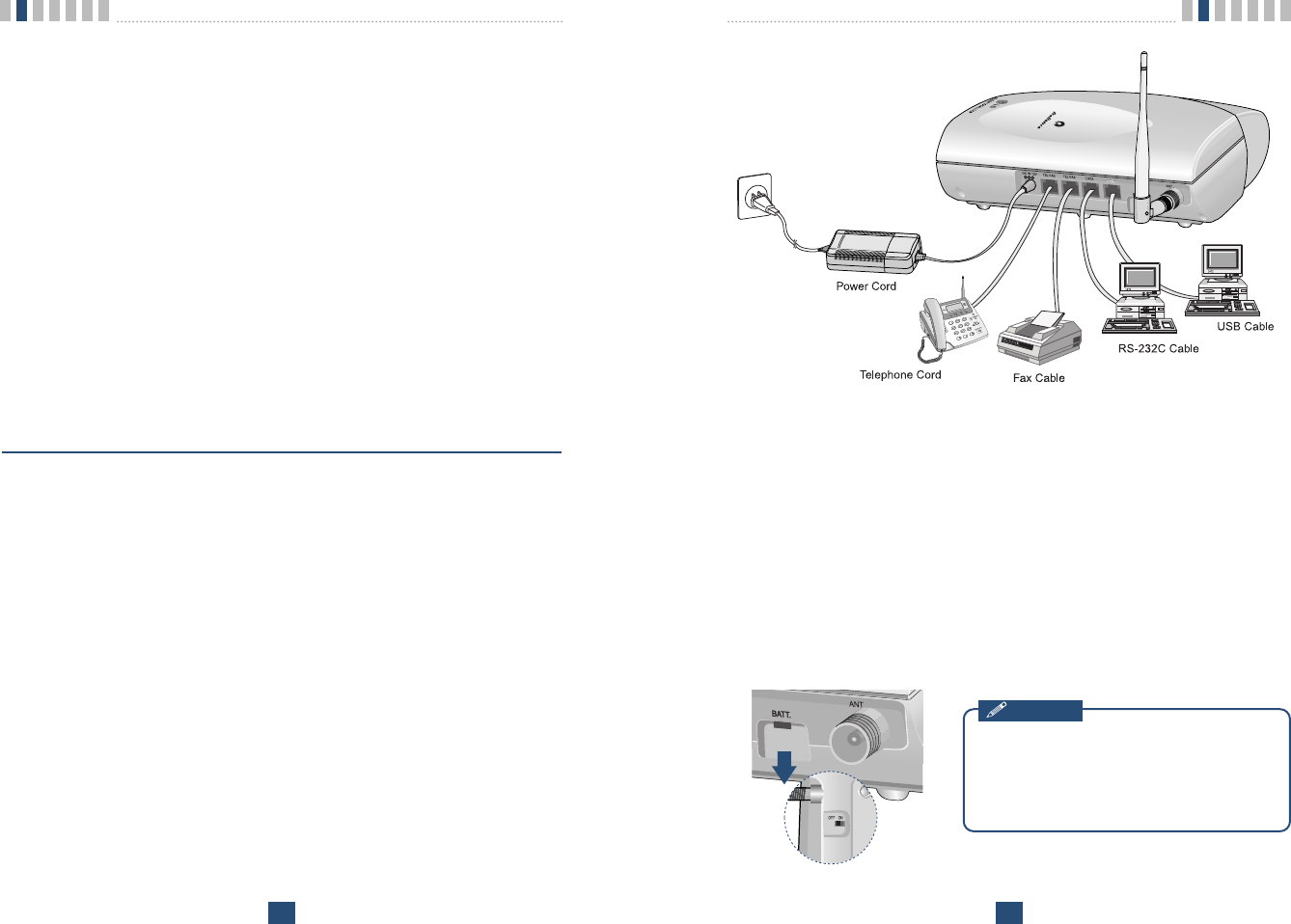
< Figure2. Connection Diagram with External Equipment >
LST-255(F)
Before using the terminal, please check
battery switch is on.
After switching on it, use the phone. When
charging the battery, check that battery
switch is Ŕonŕ.
Notice
ƅConnect your phone cord to the RJ-11 port located at the side of the termi-
nal.
ƅConnect the battery cable to the DC battery connector at the side of the ter-
minal.
- Remove the battery compartment cover.
- Connect battery to the connector.
- Replace the battery cover.
ƅConnect the AC power supply cable to the DC input port located at the side
of the terminal.
ƅIf you use Data Service or PC FAX Service, connect your RS-232C cable
cord to the RJ-45 port or USB cable cord to the USB port located at the
side of the terminal.
ƅIf you use G3 FAX machine, connect your line cord of G3 FAX to the RJ-
11 port located at the side of the terminal. (only LST-255F)
ŔRefer to connection Diagram with external equipment in Figure 2ŕ
STEP IV. Check LED Indicators
ƅWhen you followed the installation instruction STEP 1 to STEP 3, please
check the LEDs for normal operation.
ƅWhen DC power is fed at the first time, LEDs will operate as follows:
After few seconds, Power LED is GREEN, if AC/DC power is applied.
If receiving signal strength is strong enough, then SIGNAL LED is GREEN.
If not, it is ORANGE or RED. And MODE LED is turned off.
Basic Operation
21
Introduction
20
Power On
1. The POWER LED indicates the present status:
ݛUsing AC Adapter : Solid GREEN
ݜUsing internal battery : Solid ORANGE
ݝUsing internal battery and battery is weak capacity: Solid RED
2. When the terminal succeeded in getting the service, SIGNAL LED indi-
cates the strength of the signal(Table 1).
Lifting handset on telephone, dial tone is heard and you can enter a
phone number.
Note:
- Not entering any key for 15 seconds warning tone will be produced.
- In the overlap dial mode, it may take over 15seconds.
- If Hot Line function is enabled, busy tone is not produced and hot line number is auto-
matically connected.
- While having maintenance request order or lock order from the system, neither dial tone
nor busy tone is produced. Instead of them, the lock tone(Ŕpi-pi-piŕ) will be heard one
time and there will be no sound and All LED s will be blinking with GREEN color simul-
taneously.
3. If the radio service is not available or radio signal is too weak to detect:
The SIGNAL LED is RED. (No Service status)
Placing a call
When lifting handset of the connected telephone (Ŕoff hookŕ), the terminal
determines whether cellular service is available.
If it is available, dial tone is produced and a number can be dialed normally.
If phone service is not available, SIGNAL LED of the terminal will be RED
and no dial tone will be heard.
If user presses Ŕ#ŕbutton after dialed the number, the terminal makes a call
immediately.
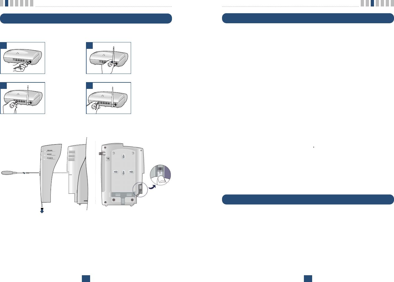
Installation Steps
Please follow the below procedure to install the unit properly.
<Terminal Connection >
<Battery Connection >
Connect the
antenna to the
TNC connector
(Turn right).
Connect your
phone Cord.
Bend the antenna
up right.
Connect the DC
Power supply.
1 2
3 4
ƅFirst, slow down the terminal slide switch and unscrew.
ƅTo connect battery, disassemble terminal like above figure.
ƅBattery connectorœs groove must be slid into the jack like above figure.

Basic Operation
23
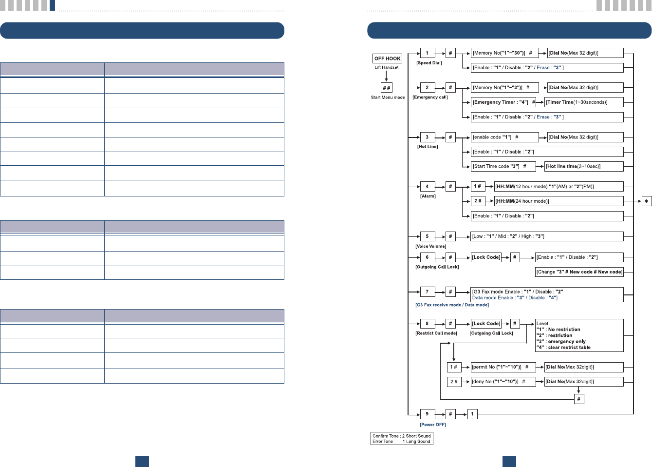
Power Off
When you need not to use terminal anymore, you should do power off before
removing AC/DC adapter cable.
Execute the Power Off
1. Press Ŕ#ŕ+ Ŕ#ŕ+ Ŕ9ŕcontinuously to enter power off mode.
2. Press Ŕ#ŕand Ŕ1ŕto ready power off.
3. Press Ŕ*ŕto execute power off.
4. After few seconds, all LED will off.
5. Turn off backup battery switch and remove AC/DC power adapter cable.
Basic Operation
22
Receiving a call
The connected telephone rings when an incoming call is detected.
Pick up the handset and begin talking.
Ending a call
When you have completed the call, place the handset back on telephone. Also
you can hook flash more than about 1 second to end a call and place a new call
without hanging up the handset.
Warning Tone after Remote Disconnect
A warning tone may be heard in the telephone after a remote party hangs up
from a call, allowing another call to be initiated after hook-flash.
Emergency Call
When emergency call number is connected once, it will not be terminated
unless the called party disconnects the call (Emergency Call Hold Service).
Therefore even caller hangs up the telephone, the line will be still connected,
so if the caller picks up the telephone again, he can continue talking.
If emergency call is connected, cellular service is not supported.
As long as your telephone is registered on a system, you can place a call to
emergency number even if your telephone is locked or restricted.
Please check the available emergency call number with your service provider.

System Features
25
Call Waiting - You can receive another incoming call during a call.
In this case, you will hear beep tone and then you can connect the second call
holding the first call by entering a code required by cellular service provider.
Your cellular service provider may require hook-flash (a quick, simulated
Ŕhang upŕ) to answer the waiting call. Other providers may require entering
the codes involving digits 1-9, *, and # to answer a waiting call.
Three-way Conference Calls - For three-way conference calls, a hook-flash
transmits the SEND command.
Please contact your cellular service provider for more information on using
this service.
ȘExample
ڡDial the first number and wait until connected:
ڢWhen connected, give hook-flash and dial the second number and give
one more hook-flash to be connected:
ڣWhen the second call is connected, give hook flash to complete a 3-way
conference call.
Voice mail - Use voice mail service in the same manner as you would on a
regular telephone. If you have a new voice-mail message, the WLL-terminal
transmits a special(4sec On / 1sec Off default) and Mode LED is blinking
(0.5sec On / 0.5sec Off). Please contact your cellular service provider for
more information on using Voice Mail or to change Voice-Mail Ring pattern.
Caller ID - LST-255(F) can support caller ID service if you have a telephone
with Caller ID feature.
*During a call, CID is not displayed.
Please contact your cellular service provider for more information on using
this service.
System Features
24
Hook flash
When the terminal receives a hook-flash from the connected telephone device,
it will automatically allow:
1. For producing dial tone again after a phone number has been dialed with-
out connection.
2. The use of special cellular services which may be available in your cellular
service area.
Note:
- Hook-flash is accomplished in a call through either pressing the dedicated hook-flash
key which is available on some phones or through a rapid single press of the hang-up
mechanism upon which the handset rests when the phone is hung up.
ROH (Receiver Off Hook)
If the telephone equipment remains Ŕoff-hookŕ, meaning that the handset is
left off of its cradle as it would be when you hang up, with no dialing activity
for about 60 seconds, a ROH tone emits from the receiver for a period of 60
seconds. After ROH tone, Line Lock Out Tone emits from receiver for a peri-
od of 60 seconds.
This feature may be different or not by country specification.
System Features
Many cellular systems offer special services such as call waiting, call forward-
ing, etc. You can purchase these services from your cellular service provider.
There are certain dialing sequences to be earned, which vary from service
provider to service provider. The service provider will provide the dialing
instructions for your system.
Call Forwarding - An incoming call can be delivered to another telephone
number programmed. Please contact your cellular service provider to use this
feature.

Programming
27
LST-255(F) provides various convenience and various features to user. This
chapter describes how to program these features and to use them. The follow-
ings are main features can be used:
Speed Dial
Emergency Call
Hot Line Call
Wake-up Alarm
Conversation Voice Level
Outgoing Call Lock
G3 Fax/Data Mode
Restrict Call
ƅProgramming Instruction
1. Lift Handset and press Ŕ#ŕkey twice and you will hear the Menu
Entering tone.
2. Enter the field number (1 ~ 9).
3. Press Ŕ#ŕkey and you will hear confirmation tone.
4. Enter sub-fields and their options.
5. Press Ŕ*ŕkey to save and you will hear confirmation tone.
Note:
-As to the characteristic quality of some telephones, confirm tone or error tone could not
be heard.
Speed Dial
LST-255(F) has 30 memory locations (1~30:1 or 2 digits) to store frequently
used phone numbers and you can make a call by pressing memory location
number only when the speed dial feature is enabled.
System Features
26
Applications
Data Communication - LST-255(F) is capable of transmitting and receiving
IS-707A FAX or modem communications.
For data communications, you will need a standard RS-232C cable or a stan-
dard USB cable to connect your PC and FWT terminal. For further informa-
tion, please contact our authorized service dealer.
Multi-extension Installations - For a multi-extension installation, make sure
that all the extensions are on-hook.
If one extension is off-hook (not hung up), none of the extensions on that line
will ring when a call is being received.

Programming
29
Emergency Call
LST-255(F) has 3 emergency call numbers (1~3) and max. 32 digits can be
stored in each emergency call number.
Entering the emergency phone number
1. Press Ŕ#ŕ+ Ŕ#ŕ+ Ŕ2ŕcontinuously to enter emergency call programming
mode.
2. Press Ŕ#ŕand one of the emergency memory location numbers (1~3).
3. Press Ŕ#ŕand the phone number (Max. 32 digits).
4. Press Ŕ*ŕto save and enable this function.
Enable or Disable emergency call
1. Press Ŕ#ŕ+ Ŕ#ŕ+ Ŕ2ŕcontinuously to enter emergency call programming
mode.
2. Press Ŕ#ŕand Enable code (Ŕ1ŕ) or Disable code (Ŕ2ŕ).
3. Press Ŕ*ŕto save.
Erase All Emergency Call Numbers
1. Press Ŕ#ŕ+ Ŕ#ŕ+ Ŕ2ŕcontinuously to enter emergency call programming
mode.
2. Press Ŕ#ŕand Ŕ3ŕto erase all emergency call numbers.
3. Press Ŕ*ŕto store.
Note1: Emergency call feature is disabled after erase operation executed
Note :
- If Emergency Call is disabled and Emergency Call number has been already pro-
grammed, you can make enable Emergency Call by pressing Ŕ#ŕ+ Ŕ#ŕ+ Ŕ2ŕ+ Ŕ#ŕ+ Ŕ1ŕ
+ Ŕ*ŕwithout entering a emergency call number again.
Programming
28
Storing the Speed Dial Number
1. Press Ŕ#ŕ+ Ŕ#ŕ+ Ŕ1ŕcontinuously to enter speed dial programming
mode.
2. Press Ŕ#ŕand one of memory numbers (1~30).
3. Press Ŕ#ŕand the phone number (Max. 32 digits).
4. Press Ŕ*ŕto store.
Enable or Disable Speed Dial
1. Press Ŕ#ŕ+ Ŕ#ŕ+ Ŕ1ŕcontinuously to enter speed dial programming mode.
2. Press Ŕ#ŕand Ŕ1ŕor Ŕ2ŕto enable or disable respectively.
Ŕ1ŕ- Speed Dial Enable
Ŕ2ŕ- Speed Dial Disable
3. Press Ŕ*ŕto store.
Erase All Speed Dials
1. Press Ŕ#ŕ+ Ŕ#ŕ+ Ŕ1ŕcontinuously to enter speed dial programming
mode.
2. Press Ŕ#ŕand Ŕ3ŕto erase all speed dials.
3. Press Ŕ*ŕto store.
Note1: Speed dial feature is disabled after erase operation executed
Operation
1. Make a speed dial function enable.
2. Lift handset and dial tone will be heard.
3. Press speed dial number and wait for dial timeout.
If user press Ŕ#ŕbutton after dialed the number, the terminal make a call
immediately.

Programming
31
Alarm
If alarm feature is enabled, you will hear ring at the programmed alarm time
every day for 1 minute.
Alarm does not ring on the state of hook off, conversation or no service.
Entering Alarm Time (12-hour Mode)
1. Press Ŕ#ŕ+ Ŕ#ŕ+ Ŕ4ŕcontinuously to enter alarm time programming
mode.
2. Press Ŕ#ŕand alarm time code Ŕ1ŕfor 12-hour mode.
3. Press Ŕ#ŕand alarm time (HHMM +am(Ŕ1ŕ) / pm(Ŕ2ŕ)).
4. In the forenoon, time range is 0000~1159.
5. In the afternoon, time range is 1200~1259 or 0100 ~1159.
6. Press Ŕ*ŕto save and enable Alarm Time.
Entering Alarm Time (24-hour Mode)
1. Press Ŕ#ŕ+ Ŕ#ŕ+ Ŕ4ŕcontinuously to enter alarm time programming
mode.
2. Press Ŕ#ŕand alarm time code Ŕ2ŕfor 24-hour mode.
3. Press Ŕ#ŕand alarm time (HHMM). (0000~2359)
4. Press Ŕ*ŕto save and enable Alarm Time.
Disable Alarm Feature
1. Press Ŕ#ŕ+ Ŕ#ŕ+ Ŕ4ŕcontinuously to enter alarm time programming
mode.
2. Press Ŕ#ŕand alarm disable code Ŕ2ŕ.
3. Press Ŕ*ŕto save.
Note :
- If Alarm is disabled and time has been already programmed, you can make enable
Alarm feature by pressing Ŕ#ŕ+ Ŕ#ŕ+ Ŕ4ŕ+Ŕ#ŕ+ Ŕ1ŕ+ Ŕ*ŕwithout entering alarm time
again.
Programming
30
Hot Line
While the Hot line function is enabled, the programmed number will be auto-
matically dialed when you pick up the handset and wait for the programmed hot
line time (2~10sec) without any key press.
Programming the Hot Line number
1. Press Ŕ#ŕ+ Ŕ#ŕ+ Ŕ3ŕcontinuously to enter Hot Line programming mode.
2. Press Ŕ#ŕand Hot Line Enable code Ŕ1ŕ.
3. Press Ŕ#ŕand Hot Line phone number (Max. 32 digits).
4. Press Ŕ*ŕto save and enable this function.
Enable the Hot Line Feature
1. Press Ŕ#ŕ+ Ŕ#ŕ+ Ŕ3ŕcontinuously to enter Hot Line programming mode.
2. Press Ŕ#ŕand Hot Line Enable code Ŕ1ŕ.
3. Press Ŕ*ŕto save.
Disable the Hot Line Feature
1. Press Ŕ#ŕ+ Ŕ#ŕ+ Ŕ3ŕcontinuously to enter Hot Line programming mode.
2. Press Ŕ#ŕand Hot Line Disable code Ŕ2ŕ.
3. Press Ŕ*ŕto save.
Programming the Hot Line Time
1. Press Ŕ#ŕ+ Ŕ#ŕ+ Ŕ3ŕcontinuously to enter Hot Line programming mode.
2. Press Ŕ#ŕand Hot Line time code Ŕ3ŕ.
3. Press Ŕ#ŕand enter desired Hot Line time (2~10 seconds).
4. Press Ŕ*ŕto save.
Note :
-If Hot Line is disabled and Hot Line number has been already programmed, you can
make enable Hot Line feature by pressing Ŕ#ŕ+ Ŕ#ŕ+ Ŕ3ŕ+ Ŕ#ŕ+ Ŕ1ŕ+ Ŕ*ŕwithout enter-
ing a Hot Line Number again.

Programming
33
Changing Outgoing LOCK Code
1. Press Ŕ#ŕ+ Ŕ#ŕ+ Ŕ6ŕ+ continuously to enter Outgoing Call Lock program-
ming mode.
2. Press Ŕ#ŕand ŔLOCK code (4 digits)ŕ.
3. Press Ŕ#ŕand Ŕ3ŕto change LOCK code.
4. Press Ŕ#ŕand Ŕnew LOCK code (4 digits)ŕ.
5. Press Ŕ#ŕand re-enter Ŕnew LOCK code (4 digits)ŕ.
6. Press Ŕ*ŕto save.
Note :
- If emergency call has been enabled, then emergency call numbers stored can be made
even when Outgoing Call Lock has been activated on the terminal.
G3 FAX / DATA Mode Setting
To activate a Data Fax call by G3 FAX connected to your LST-255(F) terminal
from the other devices (Land or Mobile Data Fax), your service provider should
support wireless data FAX. And the LST-255(F) mode should be changed to G3
FAX mode to change data path from RS-232C to G3 FAX machine. Because
the terminal doesn’t recognize the call is for FAX or voice before being
response. Following is the procedure to change data path and default data path
is RS-232C data path.
Once G3 Fax mode is set, if AC power is gone and turned on again, the saved
G3 Fax mode value is restored.
Enable or Disable G3 FAX mode (Only LST-255F)
1. Press Ŕ#ŕ+ Ŕ#ŕ+ Ŕ7ŕcontinuously to enter G3 FAX/DATA programming
mode.
2. Press Ŕ#ŕand Enable (Ŕ1ŕ) or Disable (Ŕ2ŕ) code.
Enable means that Data call path is changed to G3 FAX.
Disable means that Data call path is changed to RS-232C. (Default mode)
3. Press Ŕ*ŕto save.
Programming
32
Volume Level
There are three voice volume levels to be controlled by software, and you can
set the level to the adequate conversation volume.
Changing the Volume Level
1. Press Ŕ#ŕ+ Ŕ#ŕ+ Ŕ5ŕcontinuously to enter Volume Level programming
mode.
2. Press Ŕ#ŕand Volume Level (1~3).
Ŕ1ŕ- LOW Level
Ŕ2ŕ- MIDDLE Level
Ŕ3ŕ- HIGH Level
3. Press Ŕ*ŕto save.
Before pressing Ŕ*ŕyou can enter volume level continuously.
Outgoing Call Lock
If you try to make an outgoing call while outgoing call lock is enabled, then you
will hear warning tone after dial time-out as an indication of entering the LOCK
code. You should enter LOCK code to make an outgoing call. LOCK code is
composed of 4 digits. Outgoing Call Lock feature is disabled as a factory set-
ting.
Enable or Disable Outgoing Call Lock
1. Press Ŕ#ŕ+ Ŕ#ŕ+ Ŕ6ŕ+ continuously to enter Outgoing Call Lock program-
ming mode.
2. Press Ŕ#ŕand ŔLOCK code (4 digits)ŕ.
3. Press Ŕ#ŕand Enable (Ŕ1ŕ) or Disable (Ŕ2ŕ) code.
4. Press Ŕ*ŕto save.

Programming
35
Restrict Call Mode Setting
While the Restrict Call function is enabled, the specified numbers cannot be
called. These specified numbers start with specific digits. The specific digits are
set according to the following procedure (Storing the Deny dial number).
Among these specified numbers you can permit some numbers by designating
start digits by following procedure (Storing the Permit dial number).
LST-255(F) has 10 Deny dial numbers (1~10), and max. 32 digits can be stored
in each Deny dial number.
LST-255(F) has 10 Permit dial number (1~10), and max. 32 digits can be stored
in each Permit dial number.
If you set Emergency call, the emergency number is not applied to this restrict
call.
Set Restrict Call Level
1. Press Ŕ#ŕ+ Ŕ#ŕ+ Ŕ8ŕ+ continuously to enter Restrict Call programming
mode.
2. Press Ŕ#ŕand ŔLOCK codeŕ(4 digits : set in Outgoing call lock).
3. Press Ŕ#ŕand restrict level (1~4).
Ŕ1ŕ- No restriction
Ŕ2ŕ- restriction
Ŕ3ŕ- Emergency only (All excepting emergency are restricted.)
Ŕ4ŕ- Clear restrict table
4. Press Ŕ*ŕto save.
Programming
34
Enable or Disable DATA mode
1. Press Ŕ#ŕ+ Ŕ#ŕ+ Ŕ7ŕcontinuously to enter G3 FAX/DATA programming
mode.
2. Press Ŕ#ŕand Enable (Ŕ3ŕ) or Disable (Ŕ4ŕ) code.
Enable means that Data mode is changed to USB mode.
Disable means that Data mode is changed to RS-232C mode.
(Default mode)
3. Press Ŕ*ŕto save.
Note 1: How to setup G3 FAX mode more easily
1. Press Ŕ#ŕ+ Ŕ#ŕ+ Ŕ7ŕcontinuously to enter G3 FAX/DATA programming
mode.
2. Press Enable (Ŕ1ŕ) or Disable (Ŕ2ŕ) code.
Enable means that Data call path is changed to G3 FAX.
Disable means that Data call path is changed to RS-232C.
(Default mode)
Note 2: Sending or receiving some documents by G3 FAX is possible only in AC power
mode. If AC power is gone, you cannot use the G3 Fax machine connected to the
LST-255(F).
Note 3: The recommended usage for this G3 FAX Mode is like this:
1. Disable G3 FAX Mode for normal usage.
- You can make a voice call using the telephone device connected to the
ŔTEL/FAXŕports of the LST-255(F).
- You can FAX a document using the G3 FAX machine connected to the
ŔTEL/FAXŕports of the LST-255(F).
2. To receive or send a document by FAX, should be set G3 FAX Mode. After
receiving the FAX document, disable G3 FAX Mode for another voice call.
3. If you want to use the LST-255(F) terminal only for G3 FAX sending or receiv-
ing other than the voice call, then keep the terminal in G3 FAX Mode enabled
state.
Note 4: If G3 FAX mode is enabled, You cannot set Data mode(USB) and then you
should disable G3 FAX mode.
If Data mode(USB) is enabled, You also cannot set G3 FAX mode and then you
should disable Data mode.

Troubleshooting
37
Troubleshooting
In the event you are unable to place or receive telephone calls, first check the
appropriate power indication on the LED. In case of no power, check the wiring
connections between the power outlet and the terminal. Check for the appropri-
ate service indication on the LED. If an adequate signal is not present, try differ-
ent locations for the better signal reception.
This will verify the condition of the telephone equipment and the internal wiring
of the telephone service to verify that it is working properly. If the telephone
system of wiring is not working properly, replace or repair the equipment as
required. The unit will not function with equipment that requires data transmis-
sion.
Contact your service provider if either of the following condition is true:
ƅThe terminal does not work and the LED indicates ŔNo Serviceŕand if
changing the locations does not resolve the problem.
ƅThe terminal does not work and the LED indicates ŔIn Serviceŕ.
ƅPower Supply - If the unit does not respond once plugged into a power sup-
ply:
- Check that the AC power source.
- Check that the Barrel Plug of the Power Supply is properly inserted into
the terminal.
- Check that the terminal Power Supply is properly plugged into the electri-
cal outlet or power source.
Warning!
1. Only Authorized Service Personnel should remove the cover of the
fixed wireless terminal for additional service. The contents of the ter-
minal contain components that present an Electric Shock Hazard if
handled improperly.
2. According to the power condition, you can hear a little noise during
connection.
For further assistance, contact your Authorized LG Distributor for service and
assistance. Please keep your Model number and Serial number ready for quicker
service.
Programming
36
Storing the Permit Dial Number
1. Press Ŕ#ŕ+ Ŕ#ŕ+ Ŕ8ŕ+ continuously to enter Restrict Call programming
mode.
2. Press Ŕ#ŕand ŔLOCK codeŕ
(4 digits : set in Outgoing call lock / default is 0000).
3. Press Ŕ#ŕand Ŕ1ŕto enter Permit Dial Number store step.
4. Press Ŕ#ŕand one of ŔMemory numberŕfor permit dial number(1~10).
5. Press Ŕ#ŕand the Ŕdigitsŕ(Max. 32digits).
6. If you want to store more Permit Dial Numbers continue from step 3.
If you want to finish at this point, Press Ŕ*ŕto save.
Storing the Deny Dial Number (Restricted dial number)
1. Press Ŕ#ŕ+ Ŕ#ŕ+ Ŕ8ŕ+ continuously to enter Restrict Call programming
mode.
2. Press Ŕ#ŕand ŔLOCK codeŕ
(4 digits : set in Outgoing call lock / default is 0000).
3. Press Ŕ#ŕand Ŕ2ŕto enter Deny Dial Number store step.
4. Press Ŕ#ŕand one of ŔMemory numberŕfor deny dial number(1~10).
5. Press Ŕ#ŕand the Ŕdigitsŕ(Max. 32digits).
6. If you want to store more Deny Dial Numbers continue from step3.
If you want to finish at this point, Press Ŕ*ŕto save.
LGE CDMA Fixed Wireless Terminal LST-255(F)
39
Quick Reference
General Information
38
LST-255(F)
ƅMain Unit
Item Description
Tx Frequency 824 ~ 849 MHz
Rx Frequency 869 ~ 894 MHz
Channel Bandwidth 1.25 MHz
Frequency Stability Ţ300 Hz
Tx Power Max. 0.2W
Rx Power Level ˅104 ~ ˅25 dBm
Size 210 x 147 x 63 mm
Weight(g) 653g ( w/o battery ) / 713g ( w/ battery )
ƅAC/DC Adapter
Item Description
Input Voltage 100V ~ 250V AC
Input Frequency 50 / 60 Hz
Output Voltage 12V(DC)
ƅInternal Back-up Battery(A)
Item Description
Capacity 8.4V NiMH
Talk duration time 2 Hours
Standby duration time 24 Hours
Charging duration time Trickle, 24 Hours

LGE CDMA Fixed Wireless Terminal LST-255(F)
41
(b) LG ELECTRONICS Inc. has not been notified by the CONSUMER of
the defects of the PRODUCT during the applicable warranty period.
(c) The PRODUCT serial number code or the accessory date code has been
removed, defaced or altered.
(d) The PRODUCT has been used with or connected to an accessory (i) not
supplied by LG ELECTRONICS Inc. or its affiliates, (ii) not fit for use
with the PRODUCT or (iii) used otherwise than in the manner intended.
(e) The seals of the PRODUCTœS battery enclosure have been broken or
show evidence of tampering or the PRODUCTœS battery has been used
in equipment other than that for which it has been specified usable by
LG ELECTRONICS Inc.
(f) All plastic surfaces and all other externally exposed parts that are
scratched or damages due to normal customer use.
(g) Breakage or damage to antenna unless caused by defects in material or
workmanship.
6. In order to derive the benefits of this warranty in respect of any defects in
the PRODUCT, the CONSUMER shall ship the PRODUCTS or part there-
of at its cost to the authorized service center of LG ELECTRONICS Inc.
LG ELECTRONICS Inc. shall bear the cost of shipping the PRODUCT or
part thereof back to the CONSUMER after the completion of the service
under this limited warranty.
NO OTHER EXPRESS WARRANTY IS APPLICABLE TO THIS
PRODUCT. THE DURATION OF ANY IMPLIED WARRANTIES,
INCLUDING THE IMPLIED WARRANTY OF MARKETABILITY OR
MERCHANTABILITY OR FITNESS FOR A PARTICULAR PURPOSE
OR USE IS LIMITED TO THE DURATION OF THE EXPRESS WAR-
RANTY HEREIN. LG ELECTRONICS Inc. SHALL NOT BE LIABLE
FOR THE LOSS OF USE OF THE PRODUCT, INCONVENIENCE,
LOSS OR ANY OTHER CONSEQUENTIAL DAMAGE, ARISING OUT
OF THE USE OF, OR INABILITY OF USE, OF THIS PRODUCT OR
FOR BREACH OF ANY EXPRESS OR IMPLIED WARRANTY,
INCLUDING THE IMPLIED WARRANTY OF MARKETABILTY OR
MERCHANTABILITY OR FITNESS APPLICABLE TO THIS PROD-
UCT.
LGE CDMA Fixed Wireless Terminal LST-255(F)
40
LIMITED WARRANTY STATEMENT
LG ELECTRONICS Inc. represents and warrants that this subscriber unit and
its accessories (ŔPRODUCTŕ) is free from defects in material and workman-
ship.
This warranty is subject to the following terms and conditions:
1. This warranty of the PRODUCT extends for a period of 12 months com-
mencing from the date of the activation or 16 months from the date of man-
ufacture whichever is less, except for the battery, for which the warranty is
9 months from the date of activation or 12 months from the date of manu-
facture whichever is less.
2. During the warranty period, LG ELECTRONICS Inc. or its authorized ser-
vice network will repair or replace, at LG ELECTRONICS Inc.’s option,
the PRODUCT or any relevant parts thereof in the event that the PROD-
UCT is found to be defective. The repaired PRODUCT or the Product/part
provided as a replacement for a defective PRODUCT/part, shall be free
from defects. The END USER/consumer purchaser of the PRODUCT or
his/her assignee (ŔCONSUMERŕ) shall not be charged (whether for parts,
labour or otherwise) for the repair or replacement of a defective PROD-
UCT during the warranty period. All replaced parts, boards or equipment
shall become the property of LG ELECTRONICS Inc.
3. The warranty in respect of a repaired or replaced PRODUCT/part shall
extend for the remaining warranty period of the repaired PRODUCT or
replacement thereof to the CONSUMER.
4. Upon request from LG ELECTRONICS Inc., the CONSUMER may be
required to provide the purchase receipt or other documentation or infor-
mation in respect of the date and place of purchase.
5. The CONSUMER shall have no coverage or benefits under this warranty
in the event that any of the following conditions are applicable:
(a) The PRODUCT has been subject to abnormal use or conditions,
improper storage, exposure to excessive moisture or dampness, expo-
sure to excessive temperatures, unauthorized modifications, unautho-
rized repair (including but not limited to use of unauthorized spare parts
in repairs), abuse, accident, Acts of God, spills of food or liquids,
improper installation and breakage or damage to antennae (otherwise
than by reason of any defects in material or workmanship).
Appendix FCC RF Exposure Information
WARNING!
The antenna used for this transmitter must not exceed 2.5dBi and must
be installed to provide a minimum separation distance of 20 cm from
all persons.
CAUTION
Use only the supplied and approved antenna. Use of unauthorized
antennas or modifications could impair call quality, damage the phone,
void your warranty and/or result in violation of FCC regulations.
Do not use the phone with a damaged antenna. If a damaged antenna
comes into contact with skin, a minor burn may result. Contact your
local dealer for a replacement of antenna.
FCC Part 15 Class B Compliance
This device and its accessories comply with part 15 of FCC rules.
Operation is subject to the
following two conditions: (1) This device and its accessories may not
cause harmful interference, and (2) this device and its accessories
must accept any interference received, including interference that may
cause undesired operation.