LG Electronics USA LTTMU10 Cellular/PCS CDMA Automotive Transceiver Module User Manual
LG Electronics USA Cellular/PCS CDMA Automotive Transceiver Module Users Manual
Users Manual
User Manual For TMU
(Preliminary)
1. Overview
TMU(Telematics Unit, Model name: LT-10MCGVH) is pre-equipped on the vehicle factory to
provide customer with various services such as Economic Driving Coach, Safety and
Security, Roadside Assistance, etc.
2. Operation
User can trigger various services TMU provides with by pressing one of 3 buttons on the
Inside Mirror
2.1. SOS – Emergency Assistance
In the event of an emergency (
e.g.,
medical, fire, police, or minor accident that doesn’t
trigger an ACN call), the customer can press the SOS button in the vehicle that connects
the vehicle occupant(s) to a Response Specialist who is able to determine the location of
the vehicle and contact the nearest PSAP (Public Safety Answering Point) to provide
Emergency Assistance quickly and efficiently.
2.2. PTT – Push To Talk
User can trigger SR(Speech Recognition) operation by pressing PTT button in order to
get serviced various function such as Economic Drive Coach, Turn by Turn Navigation
and TMU information quarry.
2.2.1. SR Command – ‘Route Summary’
Show the route summary
2.2.2. SR Command – ‘Cancel Route’
Cancel the current route
2.2.3. SR Command – ‘Suspend Route’
Suspend the current route
2.2.4. SR Command – ‘Resume Route’
Resume the previously suspended route
2.2.5. SR Command – ‘Route Preview’
Preview the route for the desired destination
2.2.6. SR Command – ‘Save Destination’
Save the desired destination with the voice name tag.
2.2.7. SR Command – ‘Navigate To’
Choose the saved destination or start the navigation
2.2.8. SR Command – ‘Daily Route’
Start the navigation for the saved daily route
2.2.9. SR Command – ‘Destination List’
Show the list of saved destinations
2.2.10. SR Command – ‘Voice Guidance’
Turn on/off the voice guidance
2.2.11. SR Command – ‘Reroute’
Recalculate the route for the current destination
2.2.12. SR Command – ‘Setup’
Set various parameters of TMU such as distance unit, voice prompt,
notifications
2.2.13. SR Command – ‘Help’
List entire SR command set.
2.3. IVR – Interactive Voice Recognition
User can connect to service provider center by pressing IVR button in order to use
various services. When the voice call is connected between user and service provider
center by IVR button, user will be directed to automatic response system or to response
specialist.
3. Modem Function
3.1. SMS
TMU utilizes most of services by SMS transfer. When SOS or IVT button is pressed or
vehicle related events occurs, TMU sends SMS to desired destination – service center or
emergency center.
3.2. Voice Call
TMU utilizes MT(Mobile Terminated) Call in general use case. When SOS or IVR button
pressed, TMU sends SMS to desired destination then wait for the incoming call from the
destination. TMU will receive incoming call automatically after SMS is sent. For the
exceptional case, TMU utilizes MO(Mobile Oriented) Call in order to send DTMF when in
emergency case the service center or emergency center is not responding for the SMS
TMU sent.
3.3. Packet Data
TMU utilizes TCP/IP connection with service center to transmit/receive packet data
through network in the case where destination/route data needs to be downloaded.
3.4. DTMF
TMU utilizes MO Call to send DTMF when in emergency case the service center or
emergency center is not responding for the SMS TMU sent.
4. Test Setup for TMU
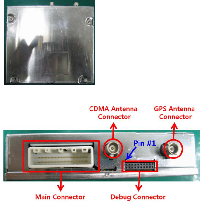
<Fig. 1 TMU Top View>
<Fig. 2 TMU Front View>
4.1. Connect main cable & Power connection.
- Connect the <Fig. 2>- Main Connector & the <Fig. 3>- Main terminal
- GND Line in the <Fig. 3>- Power & GND Line links ground pin in Power Supply.
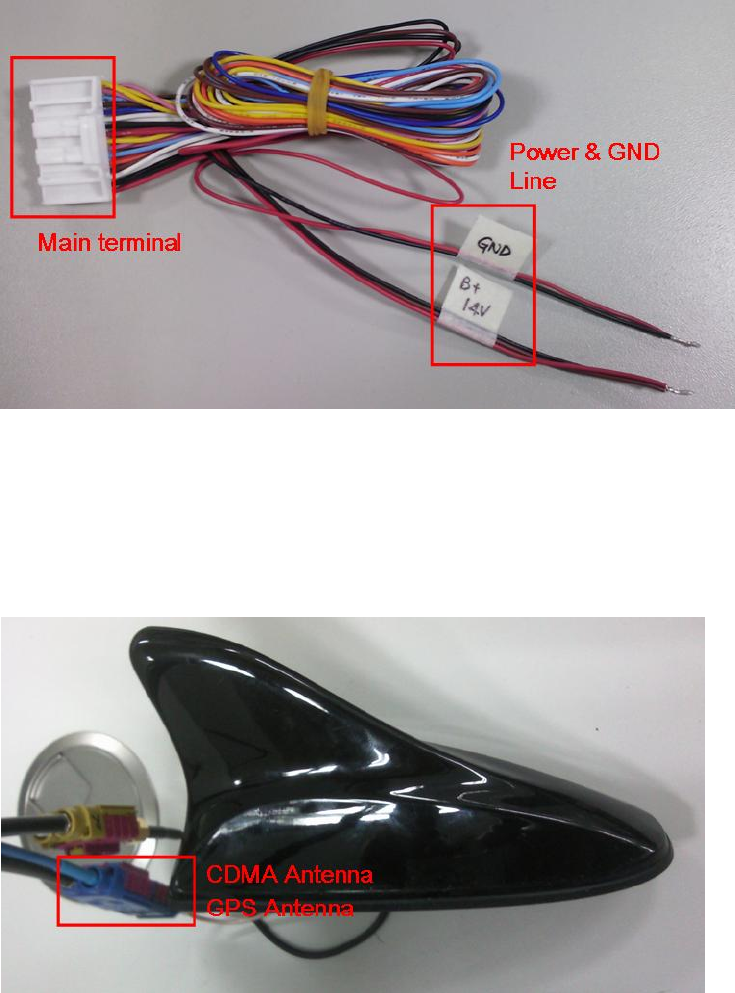
- B+14V Line in the <Fig. 3>- Power & GND Line links 14V-power.
<Fig. 3 TMU Main Cable>
4.2. Connect GPS & CDMA Antenna.
- CDMA & GPS Antenna in the <Fig. 4> are connected to CDMA & GPS Antenna
connector in the <Fig. 2>
<Fig. 4 Antenna>
“In order to comply with FCC RFx requirements, the EUT must be installed such that there is
a minimum separation distance of 20 cm between the antenna and all persons during normal
operation. The maximum cellular gain cannot exceed 9.72 dBi and the PCS antenna gain
cannot exceed 7.73 dBi.”
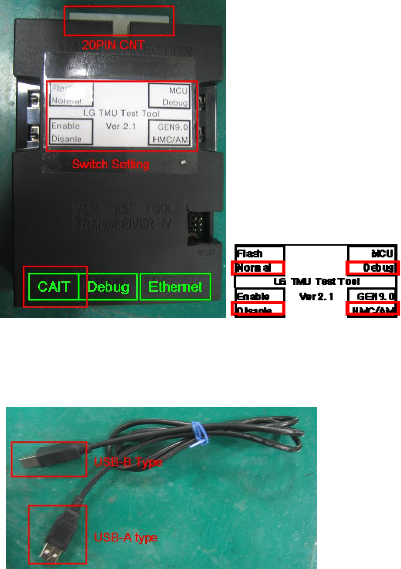
4.3. LG Test Tool Setting.
- Check the switch setting in LG test tool: Reference <Fig. 5-2>
<Fig. 5-1 LG TMU Test Tool> <Fig. 5-2 Initial Switch Setting>
- CAIT port in the LG TMU Test tool should be connected to PC with USB cable as
<Fig. 6>
<Fig. 6 USB Cable>
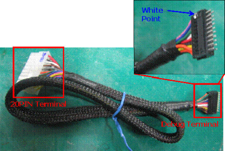
- 20Pin Terminal in the <Fig. 7> is connected to 20Pin Connector in the <Fig. 5-1>.
<Fig. 7 LG TMU Test Tool Cable>
4.4. Connection TMU & LG TMU Test Tool.
- Debug Terminal in the <Fig. 7> is connected to Debug connector in the <Fig. 2>
# Caution : White Point in Debug terminal matches Pin #1 in the <Fig 2.> <