LG Electronics USA M1917TD 19" LCD Monitor User Manual User s Manual H ok
LG Electronics USA 19" LCD Monitor User s Manual H ok
users manual

EUT Type: 19” LCD Monitor
FCC ID: BEJM1917TD
Test Report No.: GETEC-E3-05-077
FCC Class B Certification
APPENDIX H
: USER’S MANUAL

Make sure to read the Important Precautions before using the product.
Keep the User's Guide(CD) in an accessible place for furture reference.
See the label attached on the product and quote this information to your
dealer when you require service.
M1717TM
M1917TM
User’s Guide
A1
This unit has been engineered and manufactured to ensure your personal
safety, however improper use may result in potential eletrical shock or fire
hazards. In order to allow the proper operation of all safeguards
incorporated in this display, observe the following basic rules for its
installation, use, and servicing.
On Safety
Use only the power cord supplied with the unit. In case you use another power
cord, make sure that it is certified by the applicable national standards if not being
provided by the supplier. If the power cable is faulty in any way, please contact the
manufacturer or the nearest authorized repair service provider for a replacement.
The power supply cord is used as the main disconnection device. Ensure that the
socket-outlet is easily accessible after installation.
Operate the display only from a power source indicated in the specifications of
this manual or listed on the display. If you are not sure what type of power supply
you have in your home, consult with your dealer.
Overloaded AC outlets and extension cords are dangerous. So are frayed power
cords and broken plugs. They may result in a shock or fire hazard. Call your service
technician for replacement.
Do not Open the Display.
There are no user serviceable components inside.
There are Dangerous High Voltages inside, even when the power is OFF.
Contact your dealer if the display is not operating properly.
To Avoid Personal Injury :
Do not place the display on a sloping shelf unless properly secured.
Use only a stand recommended by the manufacturer.
To Prevent Fire or Hazards:
Always turn the display OFF if you leave the room for more than a short period
of time. Never leave the display ON when leaving the house.
Keep children from dropping or pushing objects into the display's cabinet
openings. Some internal parts carry hazardous voltages.
Do not add accessories that have not been designed for this display.
During a lightning storm or when the display is to be left unattended for an
extended period of time, unplug it from the wall outlet.
Important Precautions
A2
Important Precautions
On Installation
Do not allow anything to rest upon or roll over the power cord, and do not place
the display where the power cord is subject to damage.
Do not use this display near water such as near a bathtub, washbowl, kitchen
sink, laundry tub, in a wet basement, or near a swimming pool.
Displays are provided with ventilation openings in the cabinet to allow the release
of heat generated during operation. If these openings are blocked, built-up heat
can cause failures which may result in a fire hazard. Therefore, NEVER:
Block the bottom ventilation slots by placing the display on a bed, sofa, rug, etc.
Place the display in a built-in enclosure unless proper ventilation is provided.
Cover the openings with cloth or other material.
Place the display near or over a radiator or heat source.
Do not rub or strike the Active Matrix LCD with anything hard as this may scratch,
mar, or damage the Active Matrix LCD permanently.
Do not press the LCD screen with your finger for a long time as this may cause
some afterimages.
Some dot defects may appear as Red, Green or Blue spots on the screen.
However, this will have no impact or effect on the display performance.
If possible, use the recommended resolution to obtain the best image quality for
your LCD display. If used under any mode except the recommended resolution,
some scaled or processed images may appear on the screen. However, this is
characteristic of the fixed-resolution LCD panel.
On Cleaning
Unplug the display before cleaning the face of the display screen.
Use a slightly damp (not wet) cloth. Do not use an aerosol directly on the display
screen because over-spraying may cause electrical shock.
On Repacking
Do not throw away the carton and packing materials. They make an ideal
container in which to transport the unit. When shipping the unit to another
location, repack it in its original material.
On Disposal
The fluorescent lamp used in this product contains a small amount of mercury.
Do not dispose of this product with general household waste.
Disposal of this product must be carried out in accordance to the regulations of
your local authority.
Connecting the Display
A3
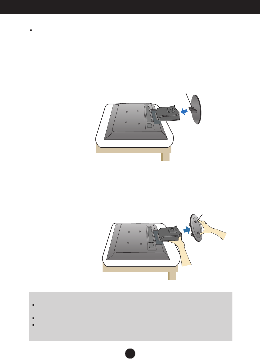
Removing the stand base
1. Place the monitor with its front facing downward on a cushion or soft cloth.
2. To remove the stand base, hold the bottom of the stand with one hand and
pull the base bottom latch with the other hand, as shown in the figure.
Before setting up the monitor, ensure that the power to the monitor, the
computer system, and other attached devices is turned off.
Connecting the stand base
1. Place the monitor with its front facing downward on a cushion or soft cloth.
2. Align the hooks on the stand base with the matching slots in the base of
the monitor.
3. Insert the hooks into slots.
Important
This illustration depicts the general model of connection. Your monitor may differ from
the items shown in the picture.
Once you connect the stand base, try not to disconnect it.
Do not carry the product upside down holding only the stand base. The product may
fall and get damaged or injure your foot.
Hook
Bottom Latch
A4
Connecting the Display
Before setting up the monitor, ensure that the power to the monitor, the computer
system, and other attached devices is turned off.
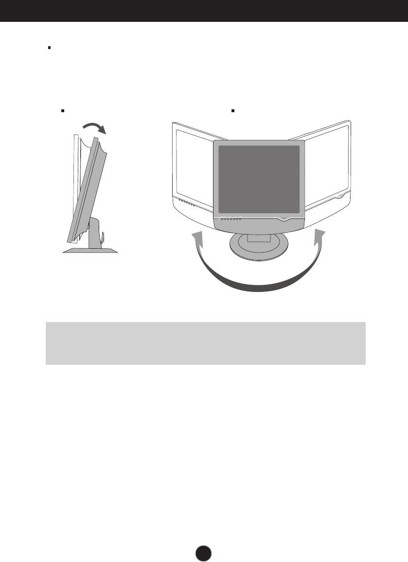
Positioning your display
1. Adjust the position of the panel in various ways for maximum comfort.
Tilt Range : -3˚~25˚ Swivel :345˚
Ergonomic
It is recommended that in order to maintain an ergonomic and comfortable viewing
position, the forward tilt angle of the monitor should not exceed 5 degrees.
Connecting the Display
A5
Using the Computer
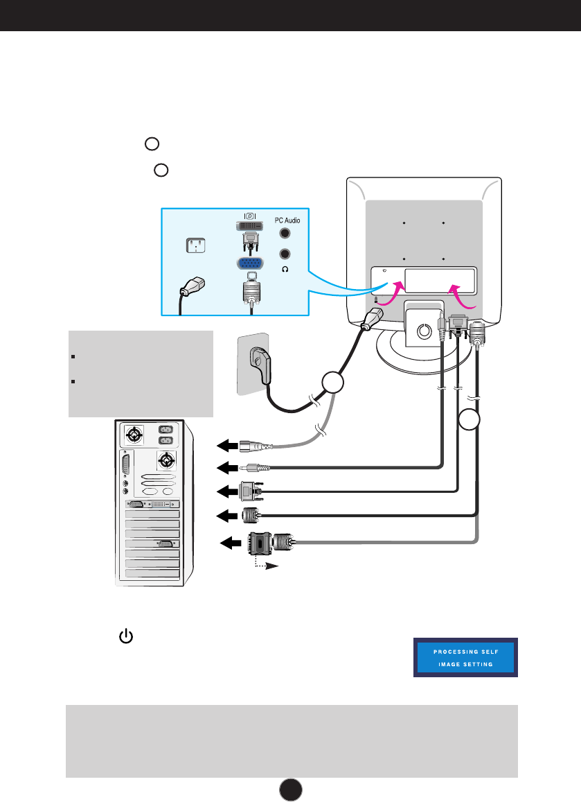
1. Place the monitor in a convenient, well-ventilated location near your computer. To adjust
height of your monitor, unlock the stand lock on top of the stand.
2. Connect the signal cable. When attached, tighten the thumbscrews to secure the
connection.
3. Connect the power cord into a proper power outlet that is easily accessible and close
to the display.
Wall-outlet type
PC-outlet type
MAC
Power Cord
Signal Cable
Varies according to model.
1
2
Mac adapter
For Apple Macintosh use, a separate plug adapter is needed to
change the 15 pin high density (3 row) D-sub VGA connector on
the supplied cable to a 15 pin 2 row connector.
4. Press button on the front switch panel to turn the power
on. When monitor power is turned on, the 'Self Image
Setting Function' is executed automatically.
(Only Analog Mode)
NOTE
‘ Self Image Setting Function’? This function provides the user with optimal display settings.When the user
connects the monitor for the first time, this function automatically adjusts the display to optimal settings for individual
input signals. If you want to adjust the monitor while in use, or wish to manually run this function once again, push
the ‘AUTO/SET’ button on the front panel of the monitor. Otherwise, you may execute the ‘ Factory reset’ option on
the OSD adjustment menu. However, be aware that this option initializes all the menu items except ‘Language’.
NOTE
This is a simplified representation
of the rear view.
This rear view represents a
general model; your display may
differ from the view as shown.
PC
PC
1
2
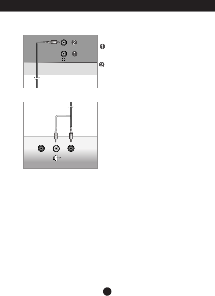
PC AUDIO
A6
Connecting the Display
Bottom
*LINE OUT
A terminal used to connect to the
speaker including a built-in amplifier
(Amp). Make sure that the connecting
terminal of the PC sound card is checked
before connecting. If the Audio Out of PC
sound card has only Speaker Out,
reduce the PC volume.
If the Audio Out of the PC sound card
supports both Speaker Out and Line Out,
convert to Line Out using the card
jumper of the program (Refer to the
Sound Card Manual).
<Jack of the PC sound card>
Headphone/Earphone Input
Automatically mutes the speaker volume
when the headphones are plugged in.
Audio Input
Connects to the *LINE OUT jack of the
PC sound card.
<Display - Back>
Speaker Out
*Line Out
A7A7
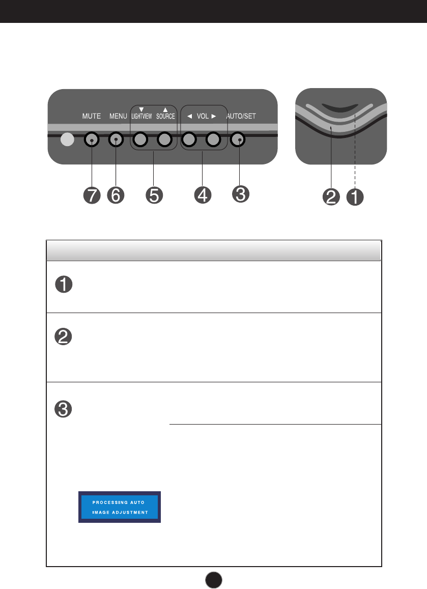
Control Panel Functions
Front Panel Controls
This Indicator lights up green when the display
operates normally(On Mode). If the display is in Sleep
Mode (Energy Saving), this indicator color changes
to amber.
Use this button to turn the display on or off.
Power Button
Power Indicator
Use this button to enter a selection in the On Screen
Display.
AUTO/SET
Button
AUTO IMAGE ADJUSTMENT
When adjusting your display settings, always press
the AUTO/SET button before entering the On Screen
Display(OSD). This will automatically adjust your
display image to the ideal settings for the current
screen resolution size (display mode).
The best display mode is
17 inch monitor : 1280x1024
19 inch monitor : 1280x1024
Control Function
A8
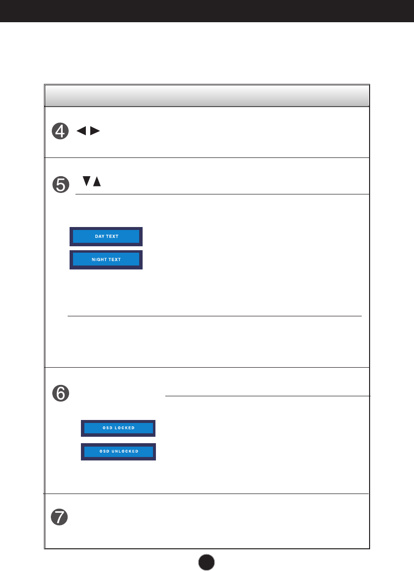
Control Panel Functions
MENU Button
Use this button to enter or exit the On Screen Display.
Control Function
OSD LOCKED/UNLOCKED
This function allows you to lock the current control
settings, so that they cannot be inadvertently changed.
Press and hold the MENU button for servaral seconds.
The message "OSD LOCKED" should appear.
You can unlock the OSD controls at any time by pushing
the MENU button for servaral seconds. The message
"OSD UNLOCKED" should appear.
Buttons
Use these buttons to select or adjust functions in the On
Screen Display.
Lightview hot key
This feature lets you easily select the best desired
image condition optimized to the environment
(ambient illumination, image types etc).
• DAY : Bright ambient illumination
• NIGHT : Dark ambient illumination
• TEXT : For text images (Word processing etc.)
• MOVIE : For animation images in videos or movies
• PHOTO : For pictures or drawings
•
NORMAL
: This is under normal operating conditions
DAY
NIGHT
Front Panel Controls
Use these buttons to decrease or increase
the volume level.
VOL Buttons
Used to select mute on (means sound off) and
mute off (means sound on).
MUTE Button
Use this button to make D-Sub or DVI connector active.
This feature is used when two computers are connected
to the display. The default setting is D-Sub.
SOURCE hot key
Screen Adjustment
Making adjustments to the image size, position and operating parameters of
the display is quick and easy with the On Screen Display Control system.
A short example is given below to familiarize you with the use of the controls.
The following section is an outline of the available adjustments and selections
you can make using the OSD.
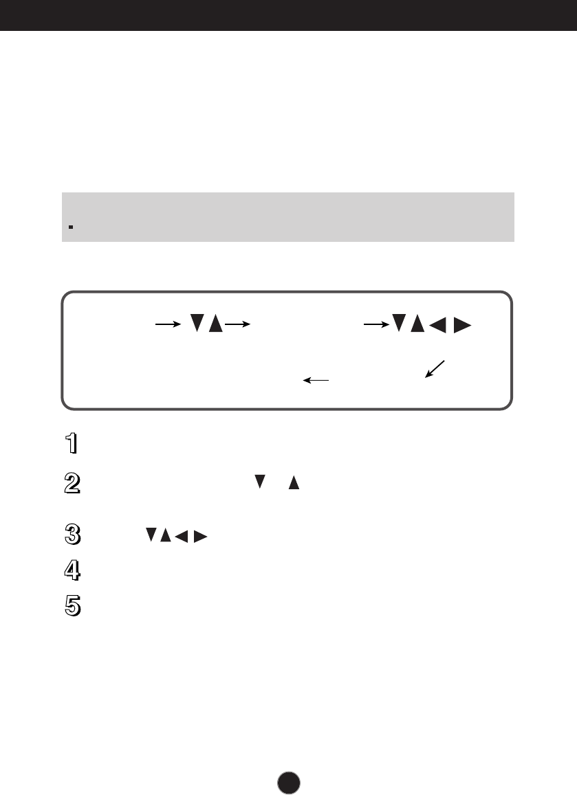
To make adjustments in the On Screen Display, follow these steps:
Press the MENU Button, then the main menu of the OSD appears.
To access a control, use the or Buttons. When the icon you want
becomes highlighted, press the AUTO/ SET Button.
Use the Buttons to adjust the item to the desired level.
Accept the changes by pressing the MENU Button.
Exit the OSD by pressing the MENU Button.
A9
On Screen Display (OSD) Control Adjustment
NOTE
Allow the display to stabilize for at least 30 minutes before making image adjustments.
AUTO/SET
MENU
MENU MENU
A10
NOTE
The order of icons may differ depending on the model (A10~A13).
On Screen Display(OSD) Selection and Adjustment
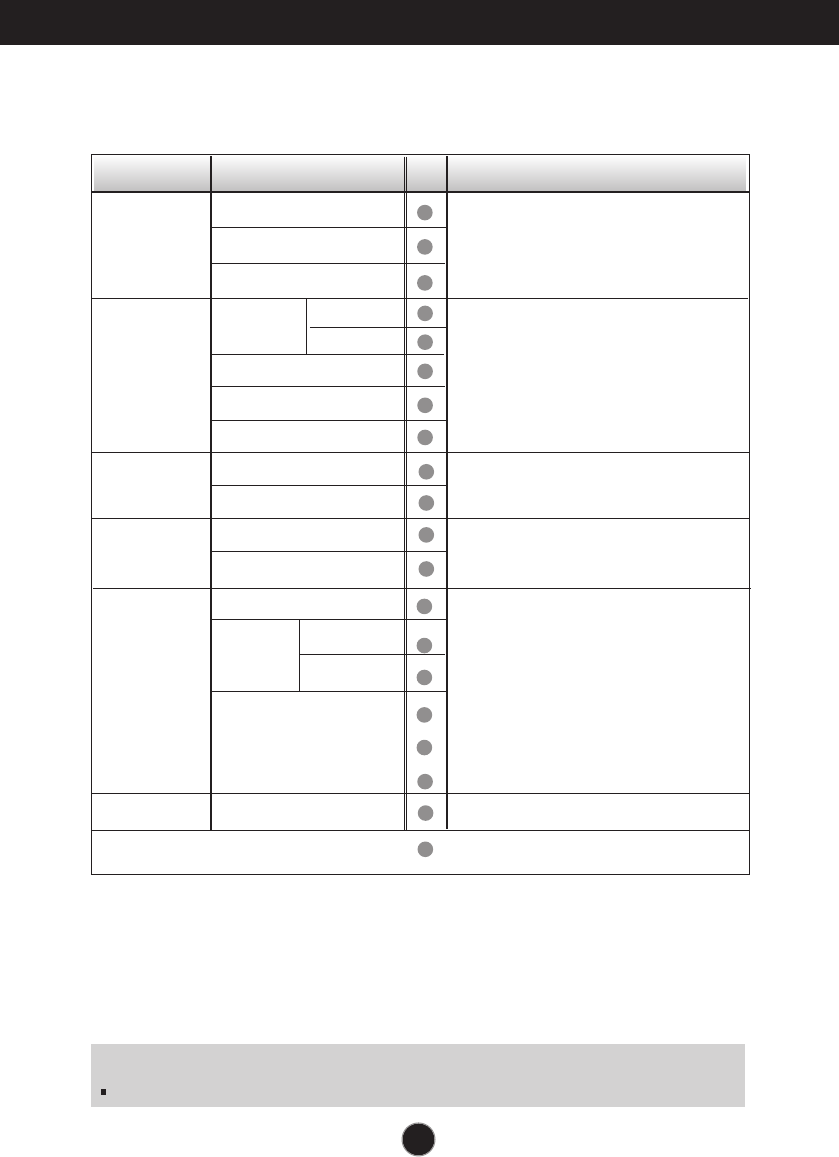
The following table indicates all the On Screen Display control, adjustment,
and setting menus.
To adjust the brightness,
contrast and gamma of the
screen
PICTURE
COLOR
POSITION
TRACKING
SETUP
AUDIO
Main menu Sub-menu Reference
PRESET
RED
GREEN
BLUE
To adjust the position of the
screen
To customize the color of
the screen
To customize the screen
status for a user's operating
environment
To improve the clarity and
stability of the screen
BRIGHTNESS
CONTRAST
GAMMA
HORIZONTAL
VERTICAL
CLOCK
PHASE
WHITE BALANCE
POWER INDICATOR
FACTORY RESET
LANGUAGE
OSD
HORIZONTAL
POSITION VERTICAL
6500K
9300K
: Adjustable
VOLUME
To adjust the audio function.

A11
On Screen Display(OSD) Selection and Adjustment
NOTE
OSD (On Screen Display) menu languages on the monitor may differ from the manual.
You were introduced to the procedure of selecting and adjusting an item
using the OSD system. Listed below are the icons, icon names, and icon
descriptions of the all items shown on the Menu.
Press the MENU Button, then the main menu of the OSD appears.
Menu Name
Icons Sub-menus
A12
On Screen Display(OSD) Selection and Adjustment
Main menu Sub menu Description
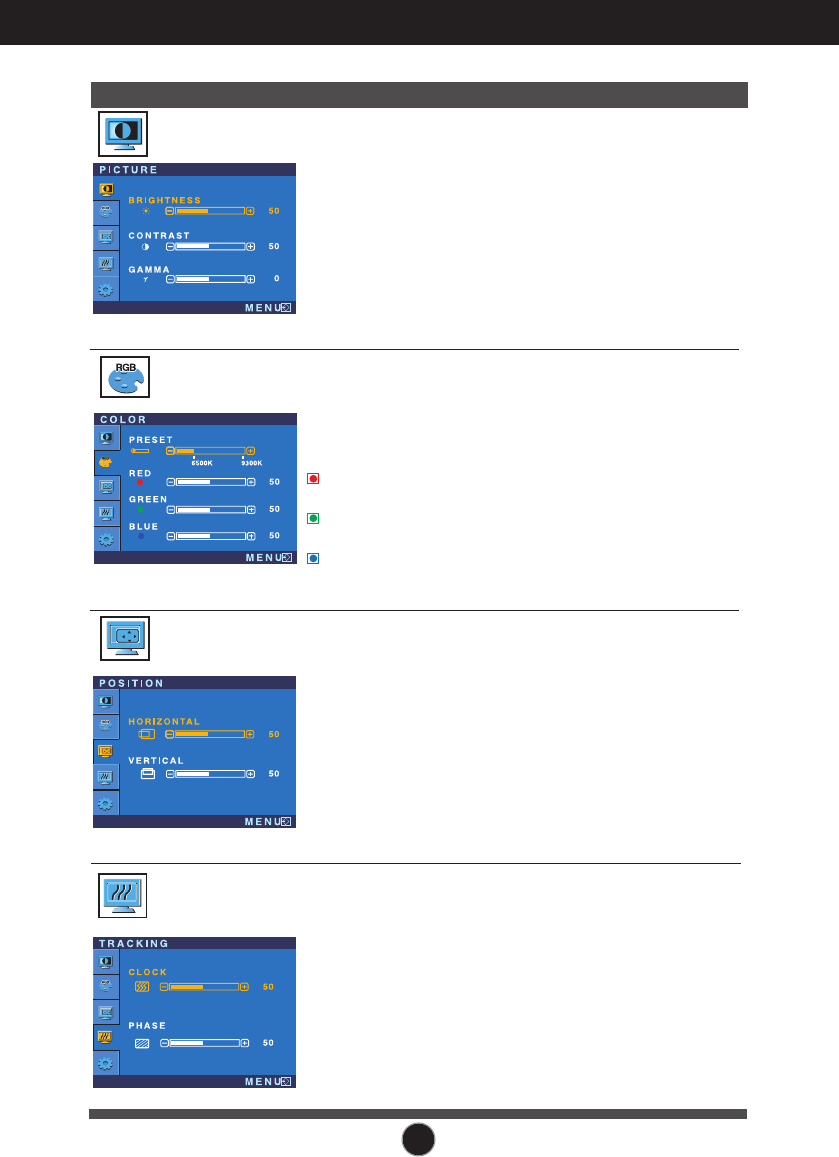
BRIGHTNESS
CONTRAST
GAMMA
To adjust the brightness of the screen.
To adjust the contrast of the screen.
Set your own gamma value. : -50/0/50
On the monitor, high gamma values
display whitish images and low gamma
values display high contrast images.
PICTURE
PRESET
RED
GREEN
BLUE
Select the screen color.
• 6500K: Slightly reddish white.
• 9300K: Slightly bluish white.
Set your own red color levels.
Set your own green color levels.
Set your own blue color levels.
COLOR
HORIZONTAL
VERTICAL
To move image left and right.
To move image up and down.
POSITION
CLOCK
PHASE
To minimize any vertical bars or
stripes visible on the screen
background.The horizontal screen
size will also change.
To adjust the focus of the display.
This item allows you to remove any
horizontal noise and clear or
sharpen the image of characters.
TRACKING
A13
On Screen Display(OSD) Selection and Adjustment
Main menu Sub menu Description
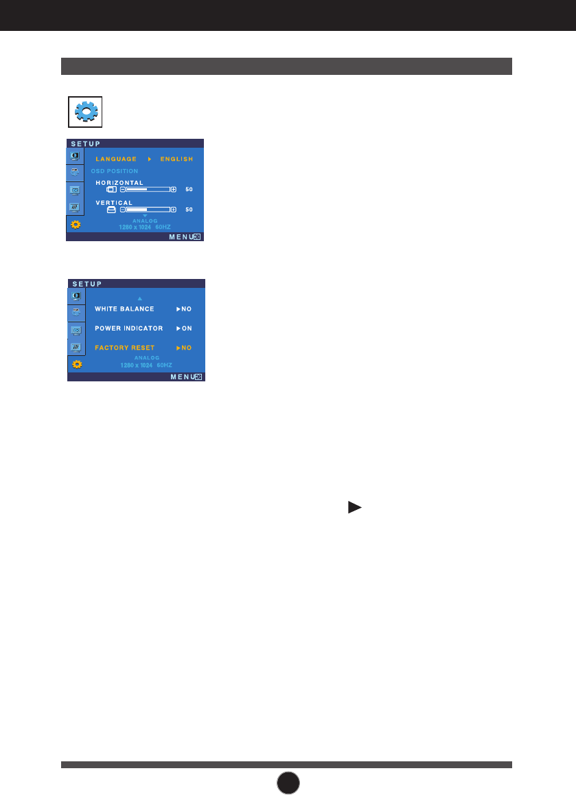
If this does not improve the screen image, restore the factory default settings.
If necessary, perform the white balance function again. This function will be enabled only when
the input signal is an analog signal.
SETUP
To choose the language in which the
control names are displayed.
To adjust position of the OSD window
on the screen.
LANGUAGE
OSD
POSITION
WHITE
BALANCE
FACTORY
RESET
If the output of the video card is different
the required specifications, the color
level may deteriorate due to video
signal distortion. Using this function, the
signal level is adjusted to fit into the
standard output level of the video card
in order to provide the optimal image.
Activate this function when white and
black colors are present in the screen.
POWER
INDICATOR
Restore all factory default settings except
"LANGUAGE."
Use this function to set the power
indicator on the front side of the monitor
to ON or OFF.
If you set OFF, it will go off.
If you set ON at any time, the power
indicator will automatically be turned on.
Press the button to reset immediately.
A14
Troubleshooting
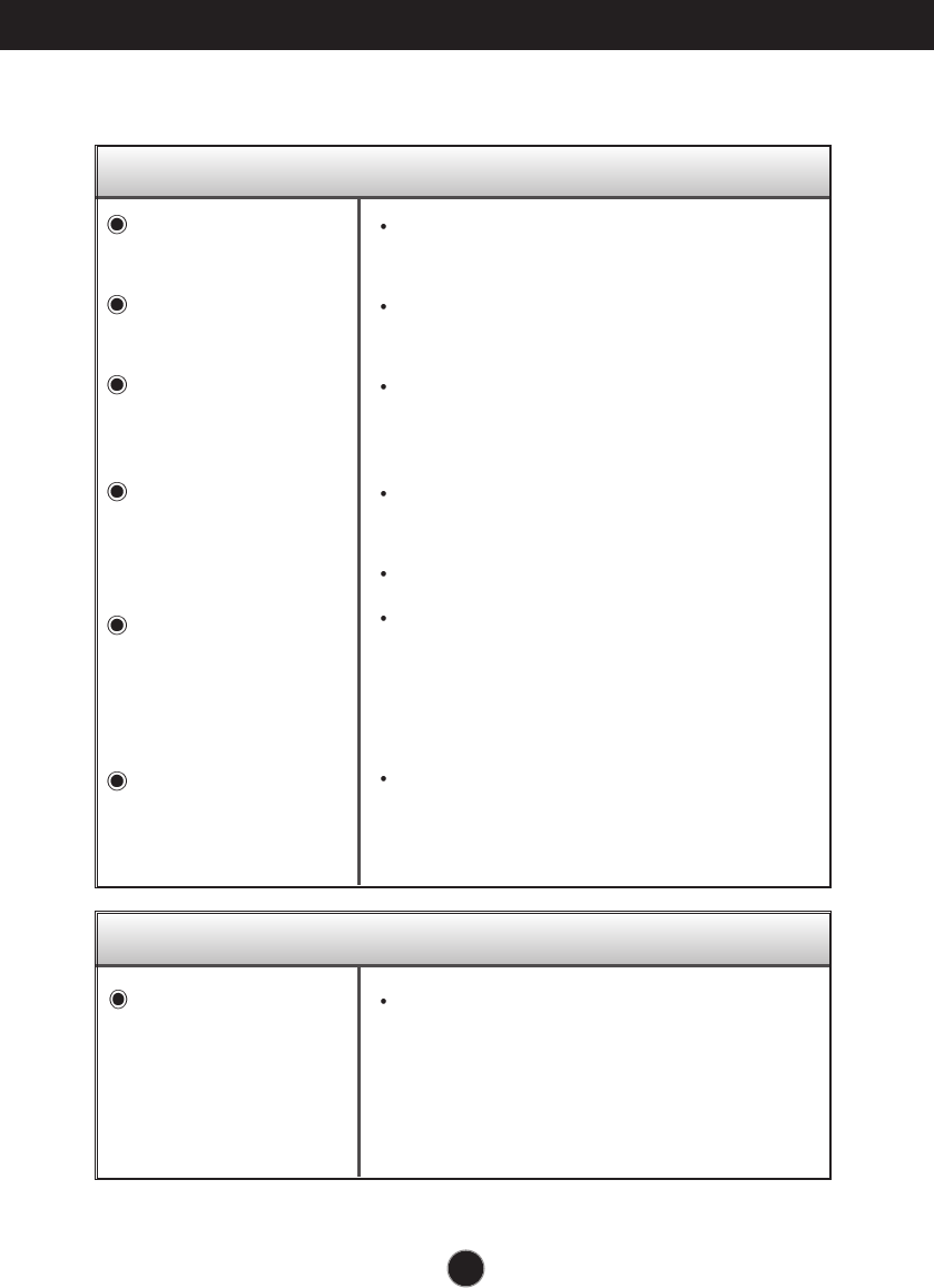
No image appears
Check the following before calling for service.
No image appears
Is the power cord of the
display connected?
Is the power indicator
light on?
Is the power on and the
power indicator blue or
green?
Is the power indicator
amber?
Do you see an "OUT
OF RANGE" message
on the screen?
Do you see a "CHECK
SIGNAL CABLE"
message on the
screen?
Do you see a "OSD LOCKED" message on the screen?
Check and see if the power cord is connected
properly to the power outlet.
Touch the Power button.
Adjust the brightness and the contrast.
If the display is in power saving mode, try moving
the mouse or pressing any key on the keyboard
to bring up the screen.
Try to turn on the PC.
This message appears when the signal from the
PC (video card) is out of horizontal or vertical
frequency range of the display. See the
'Specifications' section of this manual and
configure your display again.
This message appears when the signal cable
between your PC and your display is not
connected. Check the signal cable and try again.
You can secure the current control settings,
so that they cannot be inadvertently
changed. You can unlock the OSD controls
at any time by pushing the MENU button for
serveral seconds: the message
“OSD UNLOCKED” will appear.
Do you see “OSD
LOCKED” when you
push MENU button?
A15
Troubleshooting
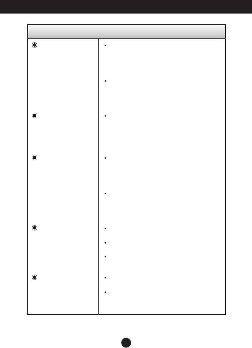
Display image is incorrect
Display Position is
incorrect.
On the screen
background, vertical
bars or stripes are
visible.
Any horizontal noise
appearing in any
image or characters
are not clearly
portrayed.
The screen color is
mono or abnormal.
The screen blinks.
Press the AUTO/SET button to automatically adjust
your display image to the ideal setting.
If the results are unsatisfactory, adjust the image
position using the H position and V position icon
in the on screen display.
Check Control Panel --> Display --> Settings and
see if the frequency or the resolution were changed.
If yes, readjust the video card to the recommend
resolution.
Press the AUTO/SET button to automatically adjust
your display image to the ideal setting.
If the results are unsatisfactory, decrease the
vertical bars or stripes using the CLOCK icon in the
on screen display.
Press the AUTO/SET button to automatically adjust
your display image to the ideal setting.
If the results are unsatisfactory, decrease the
horizontal bars using the PHASE icon in the on
screen display.
Check Control Panel --> Display --> Settings and
adjust the display to the recommended resolution or
adjust the display image to the ideal setting. Set the
color setting higher than 24 bits (true color).
Check if the signal cable is properly connected and
use a screwdriver to fasten if necessary.
Make sure the video card is properly inserted in the
slot.
Set the color setting higher than 24 bits (true color)
at Control Panel - Settings.
Check if the screen is set to interlace mode and
if yes, change it to the recommend resolution.
Make sure the power voltage is high enough, It has
to be higher than AC100-240V 50/60Hz.
A16
Troubleshooting
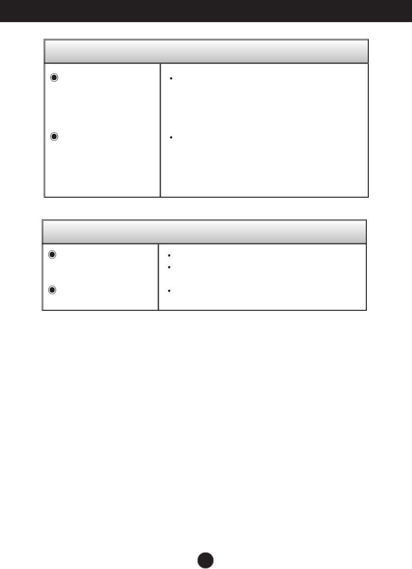
Have you installed the display driver?
Have you installed the
display driver?
Do you see an
"Unrecognized monitor,
Plug&Play (VESA DDC)
monitor found"
message?
Be sure to install the display driver from the
display driver CD (or diskette) that comes with
your display. Or, you can also download the
driver from our web site: http://www.lge.com.
Make sure to check if the video card supports
Plug&Play function.
Audio function
Check if the audio cable is correctly connected.
Check the volume level.
Check the volume level.
No sound.
Sound level is too low.

A17
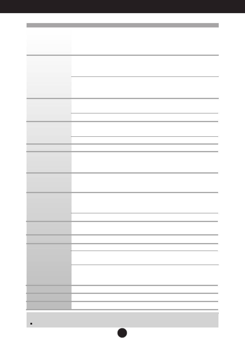
Specifications 17inch
17 inches (43.2cm) Flat Panel Active matrix-TFT LCD
Anti-Glare coating
17 inches viewable
0.264 mm pixel pitch
Horizontal Freq. Analog : 30 - 83kHz (Automatic)
Digital : 30 - 71kHz (Automatic)
Vertical Freq. 56 - 75Hz (Automatic)
Input Form Separate TTL,
SOG (Sync On Green)
Digital
Signal Input 15 pin D-Sub Connector
DVI - D connector (Digital)
Input Form RGB Analog (0.7Vp-p/75ohm), Digital
Max Analog: VESA 1280 x 1024@75Hz
Digital: VESA 1280 x 1024@60Hz
Recommend VESA 1280 x 1024@60Hz
DDC 2B
RMS Audio Output
1W+1W(R+L)
Input Sensitivity
0.7Vrms
Speaker Impedance
16Ω
On Mode
:
37W
Sleep Mode
≤1W
Off Mode ≤1W
Width 38.95 cm / 15.33 inches
Height 43.79 cm / 17.24 inches
Depth 23.20 cm / 9.13 inches
Net 5.28 kg (11.64 lbs)
Tilt -3˚~25˚
Swivel 345˚
AC 100-240V~ 50/60Hz 1.0A
Operating Conditions
Temperature 10˚C to 35 ˚C
Humidity 10 % to 80 % non-Condensing
Storage Conditions
Temperature -20˚C to 60 ˚C
Humidity 5 % to 95 % non-Condensing
Attached( O ), Detached ( )
Attached( ), Detached ( O )
Wall-outlet type or PC-outlet type
Display
Sync Input
Video Input
Resolution
Plug&Play
Audio
Power
Consumption
Dimensions
&Weight
(with tilt stand)
Tilt Range
Power Input
Environmental
Conditions
Tilt Stand
Signal cable
Power cord
NOTE
Information in this document is subject to change without notice.
A18
Specifications 19inch
19 inches (48.18cm) Flat Panel Active matrix-TFT LCD
Anti-Glare coating
19 inches viewable
0.294 mm pixel pitch
Horizontal Freq. Analog : 30 - 83kHz (Automatic)
Digital : 30 - 71kHz (Automatic)
Vertical Freq. 56 - 75Hz (Automatic)
Input Form Separate TTL,
SOG (Sync On Green)
Digital
Signal Input 15 pin D-Sub Connector
DVI - D connector (Digital)
Input Form RGB Analog (0.7Vp-p/75ohm), Digital
Max Analog: VESA 1280 x 1024@75Hz
Digital: VESA 1280 x 1024@60Hz
Recommend VESA 1280 x 1024@60Hz
DDC 2B
RMS Audio Output
1W+1W(R+L)
Input Sensitivity
0.7Vrms
Speaker Impedance
16Ω
On Mode
:
42W
Sleep Mode
≤1W
Off Mode ≤1W
Width 44.36 cm / 17.46 inches
Height 47.56 cm / 18.72 inches
Depth 23.20 cm / 9.13 inches
Net 5.98 kg (13.18 lbs)
Tilt -3˚~25˚
Swivel 345˚
AC 100-240V~ 50/60Hz 1.0A
Operating Conditions
Temperature 10˚C to 35 ˚C
Humidity 10 % to 80 % non-Condensing
Storage Conditions
Temperature -20˚C to 60 ˚C
Humidity 5 % to 95 % non-Condensing
Attached( O ), Detached ( )
Attached( ), Detached ( O )
Wall-outlet type or PC-outlet type
Display
Sync Input
Video Input
Resolution
Plug&Play
Audio
Power
Consumption
Dimensions
&Weight
(with tilt stand)
Tilt Range
Power Input
Environmental
Conditions
Tilt Stand
Signal cable
Power cord
NOTE
Information in this document is subject to change without notice.
A19
Specifications
Preset Modes (Resolution)
Display Modes (Resolution) Horizontal Freq. (kHz) Vertical Freq. (Hz)
1
2
3
4
5
6
7
8
9
10
11
*12
**13
640 x 350
720 x 400
640 x 480
640 x 480
800 x 600
800 x 600
832 x 624
1024 x 768
1024 x 768
1152 x 870
1152 x 900
1280 x 1024
1280 x 1024
31.469
31.468
31.469
37.500
37.879
46.875
49.725
48.363
60.023
68.681
61.805
63.981
79.976
70
70
60
75
60
75
75
60
75
75
65
60
75
VGA
VGA
VGA
VESA
VESA
VESA
MAC
VESA
VESA
MAC
VESA
VESA
VESA
*Recommend Mode
**
Only Analog Mode
Indicator
On Mode
Sleep Mode
Off Mode
Green
Amber
Off
Mode LED Color
A20
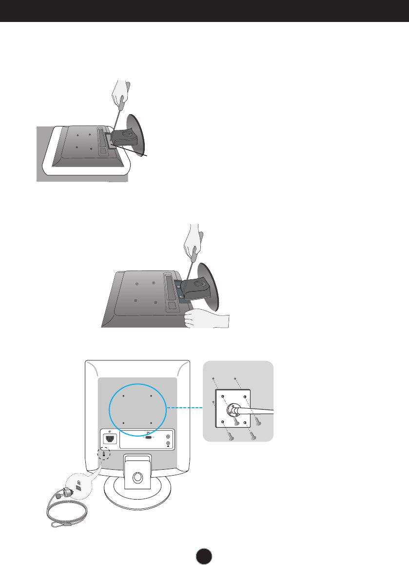
How to Install the Rack wall mounting
This monitor meets VESA-compliant mounting interface pad
specifications.
1.
Separate the stand Cover using a screwdriver as shown in the
picture.
2.
Please the monitor on a piece of cloth or other soft surface with the
front side facing downward.
3.
Separate the stand base using a screwdriver as shown in the picture.
4.
Install the VESA standrad wall mounting.
VESA wall mounting
Connected to another object
(stand type and wall-mounted
type. This monitor accepts a
VESA-compliant mounting
interface pad.-optional)
For further information, refer to
the VESA Wall Mounting
Instruction Guide.
Stand Cover
PC Audio
Kensington Security Slot- optional
Connected to a locking
cable that can be purchased separately at most computer stores

Digitally yours
Regulatory information
Regulatory information
Regulatory Information cont.
FCC Compliance Statement
This equipment has been tested and found to comply
within the limits of a Class B digital device pursuant to Part
15 of the FCC Rules. These limits are designed to provide
reasonable protection against harmful interference in a
residential installation.
This equipment generates, uses, and can radiate radio
frequency energy and if not installed and used in
accordance with the instructions, may cause harmful
interference to radio communications. However, there is
no guarantee that interference will not occur in a particular
installation.
If this equipment does cause harmful interference to radio
or television reception (which can be determined by
turning the equipment on and off), the user is encouraged
to try to correct the interference by using one or more of
the following measures:
Reorient or relocate the receiving antenna.
Increase the separation between the equipment and
the receiver.
Connect the equipment into an outlet on a circuit
different from that to which the receiver is connected.
Consult the dealer or an experienced radio/TV
technician for help.
Caution: Changes or modifications not expressly approved
by the party responsible for compliance could void the
user's (or your) authority to operate the equipment. Only
peripherals (digital input/output devices, terminals, printers,
etc.) certified to comply with the Class B limits may be
attached to this monitor. Operation with non-certified
peripherals is likely to result in interference to radio and TV
reception. Only shielded signal cables may be used with
this System.
Canadian DOC Notice
This Class B digital apparatus meets all requirements of
the Canadian Interference-Causing Equipment
Regulations. Cet appareil numérique de la classe B
respecte toutes les exigences du Règlement sur le
matériel brouilleur du Canada.
CE Conformity Notice
(for Europe)
Products with the “CE” Marking comply with the EMC
Directive(89/336/EEC) and LOW VOLTAGE Directive
(73/23/EEC) issued by the Commission of the European
Community.
Compiance with these directives implies conformity to the
following European Norms :
• EN 55022 ; Radio Frequency Interference
• EN 55024 ; Electromagnetic Immunity
• EN 61000-3-2 ; Power Line Harmonics
• EN 61000-3-3 ; Voltage Fluctuations
Low Radiation Compliance (MPR II)
This monitor meets one of the strictest guidelines available
today for low radiation emissions, offering the user extra
shielding and an antistatic screen coating. These
guidelines, set forth by a government agency in Sweden,
limit the amount of emission allowed in the Extremely Low
Frequency (ELF) and Very Low Frequency (VLF)
electromagnetic range.
TCO95 (TCO95 applied model only)
Congratulations!
You have just purchased a TCO’95 approved and labelled
product! Your choice has provided you with a product
developed for professional use. Your purchase has also
contributed to reducing the burden on the environment and
to the further development of environmentally-adapted
electronic products.
01
NOTICE
The regulations are applied only to the products with the
ID LABEL indicating specific requirements.
NOTICE
The regulations are applied only to the products with the
ID LABEL indicating specific requirements.
NOTICE
The regulations are applied only to the products with the
ID LABEL indicating specific requirements.
Regulatory Information cont.
02
Why do we have environmentally labelled computers?
In many countries, environmental labelling has become an
established method for encouraging the adaptation of
goods and services to the environment. The main problem
as far as computers and other electronic equipment are
concerned is that environmentally harmful substances are
used both in the products and during their manufacture.
Since it has not been possible so far for the majority of
electronic equipment to be recycled in a satisfactory way,
most of these potentially damaging substances sooner or
later enter Nature.
There are also other characteristics of a computer, such as
energy consumption levels, that are important from both
the working and natural environment viewpoints. Since all
types of conventional electricity generation have a
negative effect on the environment (acidic- and climatic-
influencing emissions, radioactive waste, etc.), it is vital to
conserve energy. Electronic equipment in offices
consumes as enormous amount of energy, since it is often
routinely left running continuously.
What does the environmenal labelling involve?
This product meets the requirements for the TCO’95
scheme, which provides for international environmental
labelling of personal computers. The labelling scheme was
developed as a joint effort by the TCO (The Swedish
Confederation of Professional Employees),
Naturckyddsföreningen (The Swedish Society for Nature
Conservation), and NUTEK (The National Board for
Industrial and Technical Development in Sweden), and
SEMKO AB (an international certification agency).
The requirements cover a wide range of issues:
environment, ergonomics, usability, emission of electrical
and magnetic fields, energy consumption and electrical
and fire safety.
The environmental demands concern, among other things,
restriction on the presence and use of heavy metals,
brominated and chlorinated flame retardants, CFCs
(freons), and chlorinated solvents. The product must be
prepared for recycling, and the manufacturer is obliged to
have an environmental plan, which must be adhered to in
each country where the company implements its
operational policy.
The energy requirements include a demand that the
computer and/or display, after a certain period of inactivity,
shall reduce its power consumption to a lower level, in one
or more stages. The length of time to reactivate the
computer shall be reasonable for the user.
Labelled products must meet strict environmental
demands, for example, in respect of the reduction of
electric and magnetic fields, along with physical and visual
ergonomics and good usability.
The following is a brief summary of the environmental
requirements met by this product. The complete
environmental criteria document may be ordered from:
TCO Development Unit
Linnegatan 14, S-11494 Stockholm, Sweden
FAX +46-8 782 92 07
E-mail (Internet): development@tco.se
Current information regarding TCO’95 approved and
labelled products may also be obtained on the Internet
using the address: http://www.tco-info.com/
TCO’95 is a co-operative project between:
Environmental requirements
Brominated flame retardants are present in printed circuit
boards, cabling, casings, and housings, and are added to
delay the spread of fire. Up to 30% of the plastic in a
computer casing can consist of flame-retardant
substances. These are related to another group of
environmental toxins, PCBs, and are suspected of giving
rise to similar harm, including reproductive damage in fish-
eating birds and mammals. Flame retardants have been
found in human blood, and researchers fear that they can
disturb fetus development.
Bio-accumulative1TCO’95 demands require that plastic
components weighing more than 25 grams must not
contain flame retardants with organically bound chlorine or
bromine.
Lead can be found in picture tubes, display screens,
solder, and capacitors. Lead damages the nervous
system and in higher doses causes lead poisoning. The
NUTEK
Naturskydds
föreningen
Närings- och teknikutvecklingsverket
SEMKO
Regulatory Information cont.
03
relevant bio-accumulative TCO’95 requirement permits
the inclusion of lead, as no replacement has yet been
developed.
Cadmium is present in rechargeable batteries and in the
color-generating layers of certain computer displays.
Cadmium damages the nervous system and is toxic in
high doses. The relevant bio-accumulative TCO’95
requirement states that batteries may not contain more
than 25 ppm (parts per million) of cadmium. The color-
generating layers of display screens must not contain any
cadmium.
Mercury is sometimes found in batteries, relays and
switches. Mercury damages the nervous system and is
toxic in high doses. The relevant bio-accumulative TCO’95
requirement states that batteries may not contain more
than 25 ppm of mercury and that no mercury is present in
any of the electrical or electronic components concerned
with the display unit.
CFCs (freons) are sometimes used for washing printed
circuit boards and in the manufacture of expanded foam
for packaging. CFCs break down ozone and thereby
damage the ozone layer in the atmosphere, causing
increased reception on Earth of ultra-violet light with
consequent increased risks of skin cancer (malignant
melanoma). The relevant TCO’95 requirement: Neither
CFCs nor HCFCs may be used during the manufacture of
the product or its packaging.
1Bio-accumulative means that the substance accumulates
within living organisms.
Shipping Package
The packaging material can be recycled, or you can save
it to return the monitor to a service center for repair or
disposal.
CFC Compounds in Distribution Packaging
Cushioning material used for shipping finished monitors
are not manufactured with nor do they contain any CFC
compounds.
Design for Disassembly/Recycling
These monitors have been designed for easy end-of-life
disassembly and recycling. Fasteners are generally of the
same type for efficient disassembly. Components made of
different materials can be easily separated and plastics
have been identified using intermational symbols to aid in
recycling.
Monitor Disposal
TCO'99 (TCO'99 applied model only)
Congratulations!
You have just purchased a TCO’99 approved and labelled
product! Your choice has provided you with a product
developed for professional use. Your purchase has also
contributed to reducing the burden on the environment and
also to the further development of environmentally
adapted electronics products.
Why do we have environmentally labelled computers?
In many countries, environmental labelling has become an
established method for encouraging the adaptation of
goods and services to the environment. With the growing
manufacture and usage of electronic equipment
throughout the world, there is a recognized concern for the
materials and substances used by electronic products
with regards to their eventual recycling and disposal. By
proper selection of these materials and substances, the
impact on the environment can be minimized.
There are also other characteristics of a computer, such as
energy consumption levels, that are important from the
viewpoints of both the work (internal) and natural (external)
environments. Electronic equipment in offices is often left
running continuously, resulting in unnecessary
consumption of large amounts of energy and additional
power generation. From the standpoint of carbon dioxide
emissions alone, it is vital to save energy.
What does labelling involve?
The product meets the requirements for the TCO’99
scheme which provides for international and environmental
labelling of personal computers and/or displays.
The labelling scheme was developed as a joint effort by the
TCO (The Swedish Confederation of Professional
Employees), Svenska Naturskyddsforeningen
(The Swedish Society for Nature Conservation) and
Statens Energimyndighet (The Swedish National
Energy Administration).
WARNING
If you need to dispose of a monitor, ask a qualified service
representative for the proper procedure. Improper disposal could
result in personal injury from implosion.
Regulatory Information cont.
04
Approval requirements cover a wide range of issues:
ecology, ergonomics, emission of electrical and
magnetical fields, energy consumption and electrical
safety.
Ecological criteria impose restrictions on the presence and
use of heavy metals, brominated and chlorinated flame
retardants, and other substances. The product must be
prepared for recycling and the manufacturing site(s) shall
be certified according to ISO14001 or EMAS registered.
Energy requirements include a demand that the system
unit and/or display, after a certain period of inactivity,
shall reduce its power consumption to a lower level in one
or more stages. The length of time to reactivate the system
unit shall be reasonable for the user.
Labelled products must meet strict environmental
demands, for example, in respect of the reduction of
electrical and magnetical fields as well as work load and
visual ergonomics.
Below you will find a brief summary of the ecological
requirements met by this product. The complete
ecological criteria document can be found at TCO
Development’s website http://www.tcodevelopment.com or
may be ordered from:
TCO Development
SE-114 94 STOCKHOLM, Sweden
Fax: +46 8 782 92 07
Email : development@tco.se
Information regarding TCO’99 approved and labelled
products may also be obtained at
http://www.tcodevelopment.com
Ecological requirements
Flame retardants
Flame retardants may be present in printed wiring board
laminates, cables, and housings. Their purpose is to
prevent, or at least to delay the spread of fire. Up to 30%
by weight of the plastic in a computer casing can consist of
flame retardant substances. Many flame retardants
contain bromine or chlorine, and these flame retardants
are chemically related to PCBs (polychlorinated
biphenyls). Both the flame retardants containing bromine
or chlorine and the PCBs are suspected of giving rise to
health effects, including reproductive damage in fish-eating
birds and mammals, due to the bio-accumulative*
processes when not disposed of in accordance with strict
standards for disposal.
TCO’99 requires that plastic components weighing more
than 25 grams shall not contain flame retardants with
organically bound bromine or chlorine. Flame retardants
are allowed in the printed wiring board laminates due to
the lack of commercially available alternatives.
Cadmium**
Cadmium is present in rechargeable batteries and in the
colour-generating layers of certain computer displays.
TCO’99 requires that batteries, the colour-generating
layers of display screens, and the electrical or electronics
components shall not contain any cadmium.
Mercury**
Mercury is sometimes found in batteries, relays and
switches. TCO’99 requires that batteries shall not contain
any mercury. It also demands that mercury is not present
in any of the electrical or electronics components
associated with the labelled unit. There is however one
exception. Mercury is, for the time being, permitted in the
back light system of flat panel monitors as there today is
no commercially available alternative. TCO aims on
removing this exception when a mercury free alternative is
available.
Lead**
Lead can be found in picture tubes, display screens,
solders and capacitors. TCO’99 permits the use of lead
due to the lack of commercially available alternatives, but
in future requirements TCO Development aims at
restricting the use of lead.
_____________________________________________
* Bio-accumulative is defined as substances which
accumulate in living organisms.
**Lead, Cadmium and Mercury are heavy metals
which are bio-accumulative.
05
Regulatory Information cont.
TCO’03
(TCO’03 applied model only)
Congratulations!
The display you have just purchased carries the TCO’03
Displays label.
This means that your display is designed,manufactured
and tested according to some of the strictest quality and
environmental requirements in the world. This makes for a
high performance product, designed with the user in focus
that also minimizes the impact on our natural environment.
Some of the features of the TCO’03 Display requirements:
Ergonomics
• Good visual ergonomics and image quality in order to
improve the working environment for the user and to
reduce sight and strain problems. Important
parameters are luminance, contrast, resolution,
reflectance, colour rendition and image stability.
Energy
• Energy-saving mode after a certain time – beneficial
both for the user and the environment
• Electrical safety
Emissions
• Electromagnetic fields
• Noise emissions
Ecology
• The product must be prepared for recycling and the
manufacturer must have a certified environmental
management system such as EMAS or ISO 14 001
• Restrictions on
chlorinated and brominated flame retardants and
polymers
heavy metals such as cadmium, mercury and lead.
The requirements included in this label have been
developed by TCO Development in co-operation with
scientists, experts, users as well as manufacturers all over
the world. Since the end of the 1980s TCO has been
involved in influencing the development of IT equipment in
a more user-friendly direction. Our labelling system started
with displays in 1992 and is now requested by users and
IT-manufacturers all over the world.
For more information, please visit
www.tcodevelopment.com
Information for Environmental Preservation
LGE. announced the 'LG Declaration for a Cleaner
Environment' in 1994, and this ideal has served as a
guiding managerial principle ever since. The Declaration is
a foundation that has allowed us to undertake
environmentally friendly activities in careful consideration
of economic, environmental, and social aspects.
We promote activities for environmental preservation, and
we specifically develop our products to embrace the
concept of environment-friendly.
We minimize the hazardous materials contained in our
products. For example, there is no cadmium to be found in
our monitors.
Information for recycling
This monitor may contain parts which could be hazardous
to the environment. It is important that this monitor be
recycled after use.
LGE. handles all waste monitors through an
environmentally acceptable recycling method. There are
several take-back and recycling systems currently in
operation worldwide. Many parts will be reused and
recycled, while harmful substances and heavy metals are
treated by an environmentally friendly method.
If you want to find out more information about our recycling
program, please contact your local LG vendor or a
corporate representative of LG.
We set our vision and policies on a cleaner world by
selecting the issue of the global environment as a task for
corporate improvement. Please visit our website for more
information about our ‘green’ policies.
http://www.lge.com/experience/social_commitment/enviro
ment.jsp
English
06
Regulatory Information cont.
Informationen zur Erhaltung der Umwelt
Im Jahr 1994 verkündete LGE die 'LG Declaration for a
Cleaner Environment' (LG Erklärung für eine sauberere
Umwelt). Seitdem dient dieses Ideal als führendes Prinzip
des Unternehmens. Diese Erklärung war die Basis für die
Durchführung von
umweltfreundlichen Aktivitäten, wobei wirtschaftliche,
umweltbezogene und soziale Aspekte in die
Überlegungen mit einbezogen wurden.
Wir fördern Aktivitäten zum Schutz der Umwelt und die
Entwicklung unserer Produkte ist darauf ausgerichtet,
unserem Konzept bezüglich Umweltfreundlichkeit gerecht
zu werden.
Wir sind darauf bedacht, den Anteil der in unseren
Produkten enthaltenen schädlichen Materialien zu
minimieren. So ist in unseren Monitoren beispielsweise
kein Kadmium zu finden.
Informationen zum Thema Recycling
Dieser Monitor enthält Teile, die umweltschädlich sein
können. Es ist unbedingt erforderlich, dass der Monitor
recycelt wird, nachdem er außer Dienst gestellt wurde.
Bei LGE. werden alle ausrangierten Monitore in einem
unter umweltbezogenen Aspekten geeigneten Verfahren
recycelt. Augenblicklich sind weltweit mehrere
Rücknahme- und Recyclingsysteme im Einsatz. Viele
Teile werden wieder verwendet und recycelt. Schädliche
Substanzen und Schwermetalle werden durch
umweltverträgliche Verfahren behandelt.
Falls Sie mehr über unser Recyclingprogramm erfahren
möchten, wenden Sie sich bitte an Ihren lokalen LG-
Händler oder einen Unternehmensvertreter von LG.
Wir richten unsere Firmenpolitik auf eine sauberere
Umwelt hin aus, indem wir umweltspezifische Aspekte als
wichtigen Punkt in die Weiterentwicklung unseres
Unternehmens einfließen lassen. Zusätzliche
Informationen über unsere ‘grüne’ Firmenpolitik erhalten
Sie auf unserer Website.
http://www.lge.com/experience/social_commitment/enviro
ment.jsp
Information sur la protection de l’environnement
LGE. a publié sa 'Déclaration en faveur d’un
environnement plus propre' en 1994 et celle-ci est restée,
depuis lors, un principe directeur de notre entreprise. Cette
déclaration a servi de base à notre réflexion et nous a
permis de prendre en compte à la fois les aspects
économiques et sociaux de nos activités, tout en
respectant l’environnement.
Nous encourageons les activités en faveur de la
préservation de l’environnement et c’est dans cet esprit
que nous développons nos produits : nous réduisons au
minimum les matières dangereuses qui entrent dans leur
composition et l’on ne trouve pas de cadmium, par
exemple, dans nos moniteurs.
Information sur le recyclage
Ce moniteur peut contenir des composants qui présentent
un risque pour l’environnement. Il est donc important que
celui-ci soit recyclé après usage.
LGE. traite les moniteurs en fin de cycle conformément à
une méthode de recyclage respectueuse de
l’environnement. Nous reprenons nos produits et les
recyclons dans plusieurs sites répartis dans le monde
entier. De nombreux composants sont réutilisés et
recyclés, et les matières dangereuses, ainsi que les
métaux lourds, sont traités selon un procédé écologique.
Si vous souhaitez plus de renseignements sur notre
programme de recyclage, veuillez contacter votre
revendeur LG ou un l’un de nos représentants.
Nous voulons agir pour un monde plus propre et croyons
au rôle de notre entreprise dans l’amélioration de
l’environnement. Pour plus de renseignements sur notre
politique “verte”, rendez visite à notre site :
http://www.lge.com/experience/social_commitment/enviro
ment.jsp
Informazioni per la tutela dell’ambiente
La LGE. ha annunciato nel 1994 la cosiddetta 'LG
Declaration for a Cleaner Environment' (Dichiarazione di
LG a favore di un ambiente più pulito), un ideale che da
allora funge da principio ispiratore della gestione
aziendale. La dichiarazione rappresenta il fondamento che
consente di intraprendere attività a favore dell'ambiente
tenendo conto degli aspetti economici, ambientali e sociali.
Deutsch
Français
Italiano
07
Espanõl
Regulatory Information cont.
Noi della LG, promuoviamo attività a favore della tutela
dell'ambiente sviluppando appositamente i nostri prodotti
per cogliere il concetto del rispetto dell’ambiente riducendo
i materiali dannosi presenti nei nostri prodotti. Ad esempio
nei nostri monitor non è presente il cadmio.
Informazioni per il riciclaggio
Il monitor può presentare componenti che potrebbero
risultare eventualmente dannosi per l'ambiente. È
importante che il monitor sia riciclato al termine del suo
utilizzo.
La LGE. gestisce tutti i monitor di rifiuto con un metodo di
riciclaggio soddisfacente dal punto di vista ambientale. In
tutto il mondo sono attualmente in funzione numerosi
sistemi di riciclaggio e recupero. I diversi componenti sono
riutilizzati e riciclati, mentre le sostanze dannose e i metalli
pesanti vengono trattati con un metodo rispettoso
dell’ambiente.
Se si desiderano maggiori informazioni in merito al
programma di riciclaggio, è consigliabile rivolgersi al
proprio rivenditore LG o ad un rappresentante aziendale
della LG.
Noi della LG impostiamo la nostra visione e le nostre
politiche a favore di un mondo più pulito ponendo la
questione dell'ambiente dal punto di vista globale come
una mansione rivolta al miglioramento della nostra
azienda. Vi invitiamo a visitare il nostro sito internet per
ulteriori informazioni sulla nostra politica “verde”.
http://www.lge.com/experience/social_commitment/enviro
ment.jsp
Información para la conservación
medioambiental
LGE. presentó la 'Declaración para un entorno más limpio
de LG' en 1994 y este ideal ha servido para guiar nuestros
principios empresariales desde entonces. La Declaración
es la base que nos ha permitido llevar a cabo tareas que
respetan el medio ambiente siempre teniendo en cuenta
aspectos sociales,
económicos y medioambientales.
Promocionamos actividades orientadas a la conservación
del medio ambiente y desarrollamos nuestros productos
específicamente para que se ajusten a la filosofía que
protege el entorno.
Reducimos al máximo el uso de materiales de riesgo en
nuestros productos. Un ejemplo de ello es la ausencia
total de cadmio en nuestros monitores.
Información para el reciclaje
Este monitor puede contener piezas que entrañen riesgos
medioambientales. Es importante reciclar este monitor
después de su utilización.
LGE. trata todos los monitores usados siguiendo un
método de reciclaje que no daña al entorno. Contamos
con diversos sistemas de recuperación y reciclaje que
funcionan a nivel mundial en la actualidad. Es posible
reciclar y reutilizar muchas de las piezas, mientras que las
sustancias dañinas y los metales pesados se tratan
siguiendo un método que no perjudique al medio
ambiente. Si desea obtener más información acerca del
programa de reciclaje, póngase en contacto con su
proveedor local de LG o con un representante empresarial
de nuestra marca.
Basamos nuestra visión y nuestras políticas en un mundo
más limpio y para ellos optamos por un entorno global
como tarea principal de nuestra evolución como empresa.
Visite nuestra página Web para obtener más información
sobre nuestras políticas ecológicas.
http://www.lge.com/experience/social_commitment/enviro
ment.jsp
Informações relacionadas à preservação
ambiental
A LGE. anunciou a 'LG Declaration for a Cleaner
Environment' (Declaração da LG para um ambiente mais
limpo) em 1994 e esse ideal tem servido desde então
como um princípio administrativo de orientação. A
Declaração é a base que nos tem permitido realizar
atividades favoráveis ao ambiente com consideração
atenta aos aspectos econômicos, ambientais e sociais.
Promovemos atividades de preservação ambiental e
desenvolvemos nossos produtos para englobar
especificamente o conceito de favorável ao ambiente.
Reduzimos os materiais perigosos contidos em nossos
produtos. Por exemplo, não há cádmio em nossos
monitores.
Português
08
Regulatory Information cont.
Informações relacionadas à reciclagem
Este monitor pode conter peças que podem representar
riscos ao ambiente. É importante que ele seja reciclado
após o uso.
A LGE. cuida de todos os monitores descartados através
de um método de reciclagem agradável ao ambiente. Há
vários sistemas de devolução e reciclagem atualmente em
operação no mundo. Muitas peças serão reutilizadas e
recicladas e as substâncias nocivas e os metais pesados
passarão por tratamento através de um método favorável
ao ambiente.
Para obter mais informações sobre nosso programa de
reciclagem, entre em contato com seu fornecedor LG local
ou com um representante corporativo da LG.
Definimos nossa visão e nossas políticas relacionadas a
um mundo mais limpo selecionando a questão do
ambiente global como uma tarefa de aprimoramento
corporativo. Visite nosso site para obter mais informações
sobre nossas políticas de meio ambiente.
http://www.lge.com/experience/social_commitment/enviro
ment.jsp
Informatie met betrekking tot het behoud van
het milieu
LGE. publiceerde in 1994 de 'LG Declaration for a Cleaner
Environment' (de LG-verklaring met betrekking tot een
schoner milieu). Deze verklaring en het ideaal van een
schoner milieu fungeren sindsdien als een bestuurlijke
leidraad voor onze onderneming. Op basis van deze
verklaring ontplooien wij milieuvriendelijke activiteiten,
waarbij er zowel met sociale en economische aspecten,
als met milieuaspecten zorgvuldig rekening wordt
gehouden.
Wij ondersteunen activiteiten die zijn gericht op het
behoud van het milieu en wij houden bij het ontwikkelen
onze producten specifiek rekening met de
milieuvriendelijkheid van onze producten.
Wij minimaliseren het gebruik van schadelijke stoffen in
onze producten. Er wordt bijvoorbeeld geen cadmium
verwerkt in onze monitors.
Informatie met betrekking tot recycling
Deze monitor bevat materialen die schadelijk zouden
kunnen zijn voor het milieu. Het is belangrijk dat deze
monitor aan het einde van zijn levensduur wordt
gerecycled.
LGE. verwerkt alle afvalmonitors via een milieuvriendelijke
recyclingmethode. Hiervoor worden er momenteel
wereldwijd verscheidene inname- en recyclingsystemen
gehanteerd. Een groot aantal onderdelen wordt opnieuw
gebruikt en gerecycled, waarbij schadelijke stoffen en
zware metalen volgens een milieuvriendelijke methode
worden verwerkt.
Voor meer informatie over ons recyclingprogramma kunt u
contact opnemen met uw plaatselijke LG-
vertegenwoordiger of een LG-vestiging.
Onze visie en ons beleid met betrekking tot een schonere
wereld vloeien voort uit het feit dat wij het milieu hebben
aangemerkt als een onderwerp dat speciale aandacht
verdient binnen onze onderneming. Bezoek onze website
voor meer informatie over ons 'groene' beleid.
http://www.lge.com/experience/social_commitment/enviro
ment.jsp
»ÌÙÓχˆËˇ ÔÓ Óı‡Ì ÓÍÛʇ˛˘ÂÈ Ò‰˚
¬ 1994 „Ó‰Û ÍÓÔÓ‡ˆËˇ LGE ÓÔÛ·ÎËÍÓ‚‡Î‡
'ƒÂÍ·‡ˆË˛ LG ÔÓ Óı‡Ì ÓÍÛʇ˛˘ÂÈ Ò‰˚',
ÍÓÚÓ‡ˇ Ò ÚÂı ÔÓ ÒÎÛÊËÚ ÓÒÌÓ‚Ì˚Ï ÔË̈ËÔÓÏ
ÛÔ‡‚ÎÂÌˡ. Õ‡ ÓÒÌÓ‚Â ˝ÚÓÈ ‰ÂÍ·‡ˆËË Ï˚ ÒÏÓ„ÎË
Ô‰ÔËÌˇÚ¸ ‰ÂÈÒڂˡ, Ó·ÂÒÔ˜˂‡˛˘ËÂ
·ÂÁÓÔ‡ÒÌÓÒÚ¸ ÓÍÛʇ˛˘ÂÈ Ò‰˚, Û‰ÂΡˇ ÔË ˝ÚÓÏ
‰ÓÎÊÌÓ ‚ÌËχÌË ˝ÍÓÌÓÏ˘ÂÒÍËÏ, ˝ÍÓÎӄ˘ÂÒÍËÏ Ë
ÒӈˇθÌ˚Ï ‡ÒÔÂÍÚ‡Ï.
Ã˚ ÒÚËÏÛÎËÛÂÏ ‰ÂˇÚÂθÌÓÒÚ¸ ÔÓ Óı‡ÌÂ
ÓÍÛʇ˛˘ÂÈ Ò‰˚, Û‰ÂΡˇ ÓÒÓ·Ó ‚ÌËχÌËÂ
‡Á‡·ÓÚÍ ̇¯ÂÈ ÔÓ‰Û͈ËË ‚ ÒÓÓÚ‚ÂÚÒÚ‚ËË Ò
ÍÓ̈ÂÔˆËÂÈ ˝ÍÓÎӄ˘ÂÒÍÓÈ ·ÂÁÓÔ‡ÒÌÓÒÚË.
Ã˚ Ò‚Ó‰ËÏ Í ÏËÌËÏÛÏÛ ÒÓ‰ÂʇÌË ÓÔ‡ÒÌ˚ı
‚¢ÂÒÚ‚ ‚ ̇¯ÂÈ ÔÓ‰Û͈ËË. Õ‡ÔËÏÂ, ‚ ̇¯Ëı
ÏÓÌËÚÓ‡ı ‚˚ Ì ̇ȉÂÚ ͇‰Ïˡ.
»ÌÙÓχˆËˇ ÔÓ ÛÚËÎËÁ‡ˆËË ÓÚıÓ‰Ó‚
›ÚÓÚ ÏÓÌËÚÓ ÏÓÊÂÚ ÒÓ‰Âʇڸ ÍÓÏÔÓÌÂÌÚ˚, ÍÓÚÓ˚Â
ÏÓ„ÛÚ Ì‡ÌÂÒÚË Û˘Â· ÓÍÛʇ˛˘ÂÈ Ò‰Â.
ÕÂÓ·ıÓ‰ËÏÓ ÛÚËÎËÁËÓ‚‡Ú¸ ÏÓÌËÚÓ ÔÓÒÎÂ
ËÒÔÓθÁÓ‚‡Ìˡ.
Nederlands Russian
09
Regulatory Information cont.
KÓÔÓ‡ˆËˇ LGE Ô‡·‡Ú˚‚‡ÂÚ ‚Ò ·‡ÍÓ‚‡ÌÌ˚Â
ÏÓÌËÚÓ˚ Ò ÔÓÏÓ˘¸˛ ˝ÍÓÎӄ˘ÂÒÍË ÔËÂÏÎÂÏÓ„Ó
ÏÂÚÓ‰‡ ÛÚËÎËÁ‡ˆËË ÓÚıÓ‰Ó‚. œÓ ‚ÒÂÏÛ ÏËÛ
‰ÂÈÒÚ‚Û˛Ú ÒËÒÚÂÏ˚ ÛÚËÎËÁ‡ˆËË ÓÚıÓ‰Ó‚ Ë ‚ÓÁ‚‡Ú‡
ËÒÔÓθÁÓ‚‡ÌÌÓÈ ÔÓ‰Û͈ËË. ÃÌÓ„Ë ÍÓÏÔÓÌÂÌÚ˚
·Û‰ÛÚ ‚ÚÓ˘ÌÓ ËÒÔÓθÁÓ‚‡Ì˚ Ë ÛÚËÎËÁËÓ‚‡Ì˚, ‚ ÚÓ
‚ÂÏˇ Í‡Í ‚‰Ì˚ ‚¢ÂÒÚ‚‡ Ë ÚˇÊÂÎ˚ ÏÂÚ‡ÎÎ˚
·Û‰ÛÚ Ó·‡·ÓÚ‡Ì˚ Ò ÔÓÏÓ˘¸˛ ˝ÍÓÎӄ˘ÂÒÍË
ÔËÂÏÎÂÏÓ„Ó ÏÂÚÓ‰‡.
«‡ ·ÓΠÔÓ‰Ó·ÌÓÈ ËÌÙÓχˆËÂÈ ÔÓ Ì‡¯ÂÈ
ÔÓ„‡ÏÏ ÛÚËÎËÁ‡ˆËË ÓÚıÓ‰Ó‚ Ó·‡˘‡ÈÚÂÒ¸ Í
ÏÂÒÚÌÓÏÛ ÔÓÒÚ‡‚˘ËÍÛ ËÎË Ô‰ÒÚ‡‚ËÚÂβ
ÍÓÔÓ‡ˆËË LG.
Ã˚ ÓËÂÌÚËÛÂÏÒˇ ̇ Ó·ÂÒÔ˜ÂÌË ˝ÍÓÎӄ˘ÂÒÍÓÈ
·ÂÁÓÔ‡ÒÌÓÒÚË, ÒÚ‡‚ˇ Ò· ˆÂθ˛ „ÎÓ·‡Î¸ÌÛ˛ Á‡˘ËÚÛ
ÓÍÛʇ˛˘ÂÈ Ò‰˚. ƒÓÔÓÎÌËÚÂθÌÛ˛ ËÌÙÓχˆË˛ Ó
̇¯ÂÈ ÔÓÎËÚËÍ ÔÓ Óı‡Ì ÓÍÛʇ˛˘ÂÈ Ò‰˚ ‚˚
ÏÓÊÂÚ ̇ÈÚË Ì‡ ̇¯ÂÏ Ò‡ÈÚÂ:
http://www.lge.com/experience/social_commitment/enviro
ment.jsp
환경 보존 정보
LG 전자는 1994년 'LG 환경 선언문'을 발표한 후 현재까지
이를 기업 경영의 이념으로 삼아왔습니다. 이 선언문을
바탕으로 LG 전자는 모든 경영 활동에서 경제성뿐만
아니라 환경성 및 사회성을 주요 의사 결정의 기준으로
삼음으로써 지속적으로 환경 친화적인 경영을 전개하고
있습니다.
본사는보다활발한환경보존활동과더불어환경
친화적 제품 개발에 주력해 왔습니다.
또한 제품에 포함되는 환경 위해 요소를 최소화하는
데에도 노력을 게을리하지 않고 있습니다. LG 전자
모니터의 경우 카드뮴을 전혀 사용하지 않는 것에서도
이러한 노력을 알 수 있습니다.
재활용 정보
본 모니터에는 환경에 위해를 주는 부품이 포함되어
있을 수도 있습니다. 따라서 사용이 끝난 모니터는
재활용하는 것이 좋습니다.
폐모니터는 모두 환경 친화적 방식으로 처리됩니다. 현재
세계적으로 운영되고 있는 회수 및 재활용 시스템에는
여러 가지가 있습니다. 대부분의 부품의 경우 재사용
또는 재활용되지만 환경 위해 물질과 중금속은 환경
친화적 방법으로 처리됩니다.
본사의 재활용 프로그램에 대한 자세한 정보는 각 지역의
LG 공급업체나 LG 기업 대표부에 문의하시기 바랍니다.
LG 전자는 기업 개선 정책의 하나로 지구 환경 문제를
채택함으로써 보다 나은 환경을 만들어 나가기 위한
비전과 정책을 수립했습니다. 본사의 친환경 정책에
대한 자세한 정보를 보시려면 아래의 웹 사이트를
방문하십시오.
http://www.lge.co.kr/about/digitallg/environment/environment.jsp
EPA (U.S.A only)
(EPA applied model only)
ENERGYSATR
is a set of power-saving guidelines
issued by the U.S. Environmental Protection
Agency(EPA).
NOM MARK (Mexico only)
As an ENERGY STAR Partner LGE U. S.
A.,Inc. has determined that this product
meets the ENERGY STAR guidelines for
energy efficiency.