LG Electronics USA M2262DL LCD TV MONITOR User Manual EMISSION TEST REPORT
LG Electronics USA LCD TV MONITOR EMISSION TEST REPORT
Users Manual

Order Number : GETEC-C1-09-204 FCC Class B Certification
Test Report Number : GETEC-E3-09-117 Page 1 / 1
EUT Type: LCD TV/Monitor
APPENDIX G
: USER’S MANUAL
FCC ID.: BEJM2262DL
Make sure to read the Safety Precautions before
using the product.
Keep the User's Guide(CD) in an accessible place
for furture reference.
See the label attached on the product and give the
information to your dealer when you ask for service.
OWNER’S MANUAL
M2262D
M2362D
M2762D
1
Safety Instructions
1
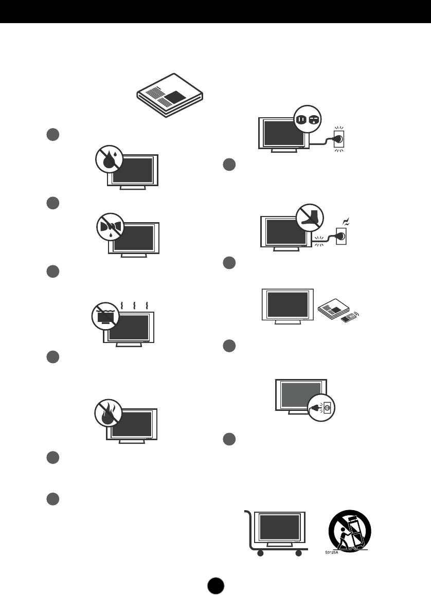
Do not use this apparatus near water.
Read these instructions.
Keep these instructions.
Heed all warnings.
Follow all instructions.
IMPORTANT SAFETY INSTRUCTIONS
2
Clean only with dry cloth.
3
Do not block any ventilation openings.
Install in accordance with the
manufacturer’s instructions.
4
Do not install near any heat sources such
as radiators, heat registers, stoves, or other
apparatus (including amplifiers) that
produce heat.
5
When mounting a TV on the wall, make
sure not to install TV by the hanging power
and signal cables on the back of the TV.
6
Do not defeat the safety purpose of the
polarized or grounding-type plug. A
polarized plug has two blades with one
wider than the other. A grounding type plug
has two blades and a third grounding
prong, The wide blade or the third prong
are provided for your safety.
7
Protect the power cord from being walked
on or pinched particularly at plugs,
convenience receptacles, and the point
where they exit from the apparatus.
If the provided plug does not fit into your
outlet, consult an electrician for
replacement of the obsolete outlet.
8
Only use attachments/accessories
specified by the manufacturer.
9
Unplug this apparatus during lightning
storms or when unused for long periods of
time.
10
Use only with the cart, stand, tripod,
bracket, or table specified by the
manufacturer, or sold with the apparatus.
When a cart is used, use caution when
moving the cart/apparatus combination to
avoid injury from tip-over.
2
Safety Instructions
11
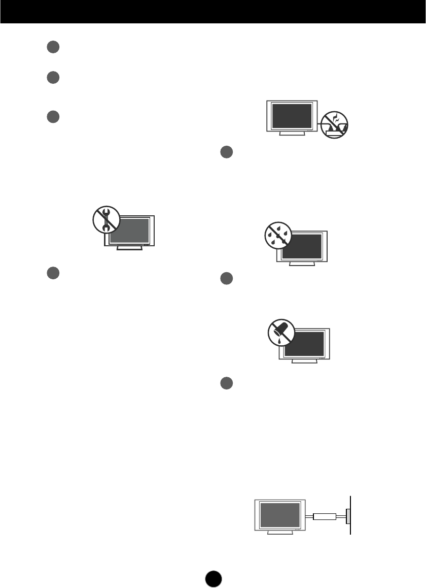
Never touch this apparatus or antenna
during a thunder or lighting storm.
12
Do not allow an impact shock or any
objects to fall into the product, and do not
drop onto the screen with something.
13 Refer all servicing to qualified service
personnel. Servicing is required when the
apparatus has been damaged in any
way, such as power-supply cord or plug
is damaged, liquid has been spilled or
objects have fallen into the apparatus,
the apparatus has been exposed to rain
or moisture, does not operate normally,
or has been dropped.
15
WARNING - To reduce the risk of fire or
electrical shock, do not expose this product
to rain, moisture or other liquids. Do not
touch the TV with wet hands. Do not install
this product near flammable objects such
as gasoline or candles or expose the TV to
direct air conditioning.
Do not move the TV with the power cord
plugged in. Do not use a damaged or loose
power cord. Be sure do grasp the plug
when unplugging the power cord. Do not
pull on the power cord to up unplug the TV.
16
Do no expose to dripping or splashing and
do not place objects filled with liquids, such
as vases, cups, etc. on or over the
apparatus (e.g. on shelves above the unit).
17
GROUNDING
Ensure that you connect the earth ground
wire to prevent possible electric shock (i.e.
a TV with a three-prong grounded AC plug
must be connected to a three-prong
grounded AC power outlet). If grounding
methods are not possible, have a qualified
electrician install a separate circuit breaker.
Do not try to ground the unit by connecting
it to telephone wires, lightening rods, or gas
pipes.
Power
Supply
Short-circuit
Breaker
14
CAUTION concerning the Power Cord:
It is recommend that appliances be placed
upon a dedicated circuit; that is, a single
outlet circuit which powers only that
appliance and has no additional outlets or
branch circuits. Check the specification
page of this owner's manual to be certain.
Do not connect too many appliances to the
same AC power outlet as this could result
in fire or electric shock.
Do not overload wall outlets. Overloaded
wall outlets, loose or damaged wall outlets,
extension cords, frayed power cords, or
damaged or cracked wire insulation are
dangerous. Any of these conditions could
result in electric shock or fire. Periodically
examine the cord of your appliance, and if
its appearance indicates damage or
deterioration, unplug it, discontinue use of
the appliance, and have the cord replaced
with an exact replacement part by an
authorized servicer. Protect the power cord
from physical or mechanical abuse, such
as being twisted, kinked, pinched, closed in
a door, or walked upon. Pay particular
attention to plugs, wall outlets, and the
point where the cord exits the appliance.
Safety Instructions
3
19
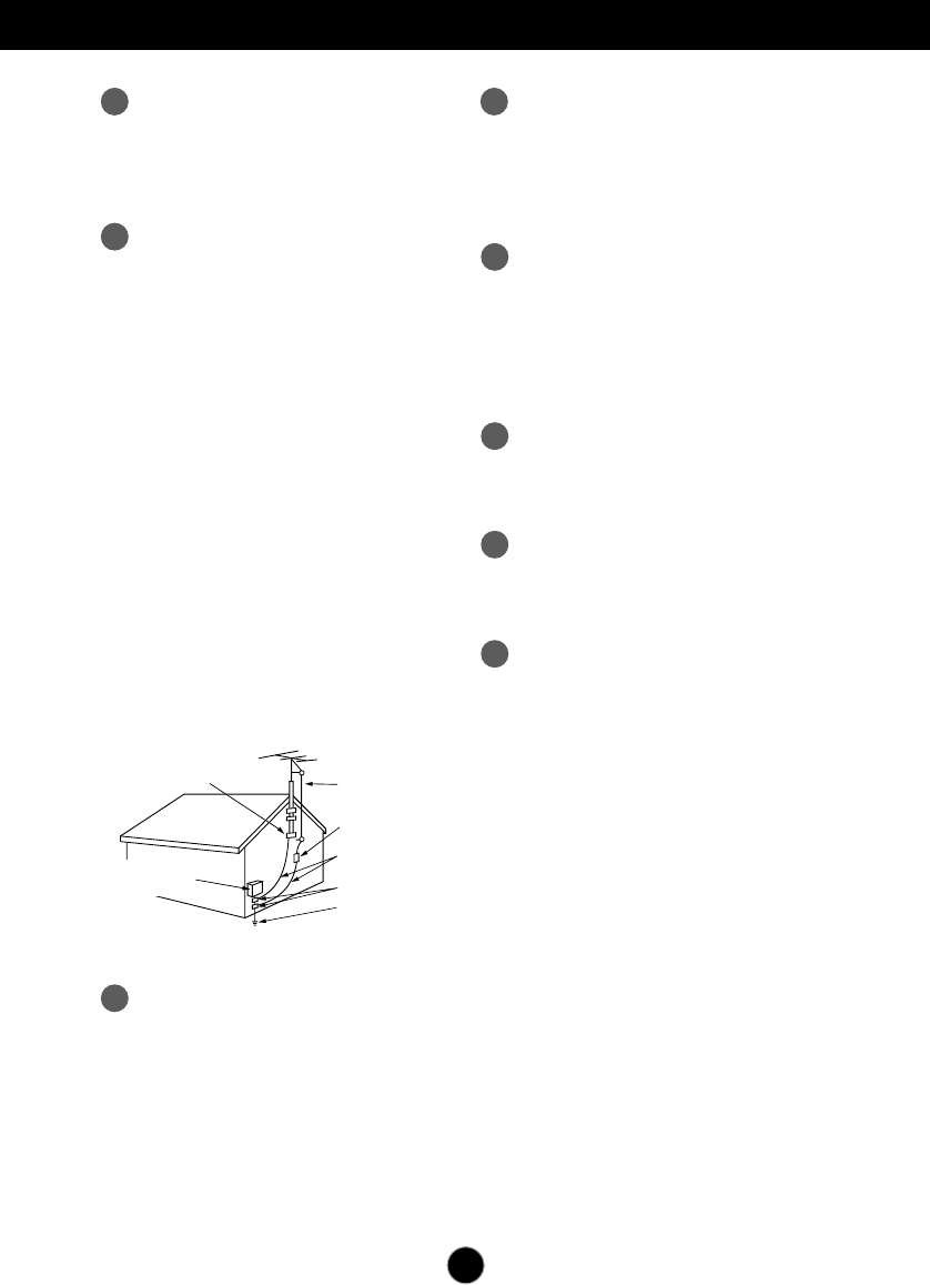
ANTENNAS
Outdoor antenna grounding
If an outdoor antenna is installed, follow the
precautions below. An outdoor antenna
system should not be located in the vicinity
of overhead power lines or other electric
light or power circuits, or where it can come
in contact with such power lines or circuits
as death or serious injury can occur.
Be sure the antenna system is grounded
so as to provide some protection against
voltage surges and built-up static charges.
Section 810 of the National Electrical Code
(NEC) in the U.S.A. provides information
with respect to proper grounding of the
mast and supporting structure, grounding
of the lead-in wire to an antenna discharge
unit, size of grounding conductors, location
of antenna discharge unit, connection to
grounding electrodes and requirements for
the grounding electrode.
Antenna grounding according to the
National Electrical Code, ANSI/NFPA 70
20
Cleaning
When cleaning, unplug the power cord and
scrub gently with a soft cloth to prevent
scratching. Do not spray water or other
liquids directly on the TV as electric shock
may occur. Do not clean with chemicals
such as alcohol, thinners or benzene.
22
Ventilation
Install your TV where there is proper
ventilation. Do not install in a confined
space such as a bookcase. Do not cover
the product with cloth or other materials
(e.g.) plastic while plugged in. Do not install
in excessively dusty places.
23
If you smell smoke or other odors coming
from the TV or hear strange sounds,
unplug the power cord contact an
authorized service center.
24
As long as this unit is connected to the AC
wall outlet, it is not disconnected from the
AC power source even if the unit is turned
off.
25
On Disposal
The fluorescent lamp used in this product
contains a small amount of mercury.
Do not dispose of this product with general
household waste.
Disposal of this product must be carried out
in accordance to the regulations of your
local authority.
NEC: National Electrical Code
Fil d entrée d antenne
Décharge d antenne
(section 810-20 du NEC)
Conducteur mis à la terre
(section 810-21 du NEC)
Pince de mise à la terre
Système d électrode
de mise à la terre (article 250,
section H du NEC)
Pince de mise à la terre
Équipement électrique
Ground clamps Antenna lead-in wire
Antenna discharge unit
(NEC Section 810-20)
Grounding conductors
(NEC Section 810-21)
Ground clamps
Power service grounding
electrode system
(NEC Art 250 Part H)
Electric service
equlpment
18
DISCONNECTING DEVICE
The power supply cord is used as the main
discon nection device. Ensure that the
socket outlet is easily accessible after
installation.
21
Moving
Make sure the product is turned off,
unplugged and all cables have been
removed. It may take 2 or more people to
carry larger TVs. Do not press against or
put stress on the front panel of the TV.
1
PREPARATION
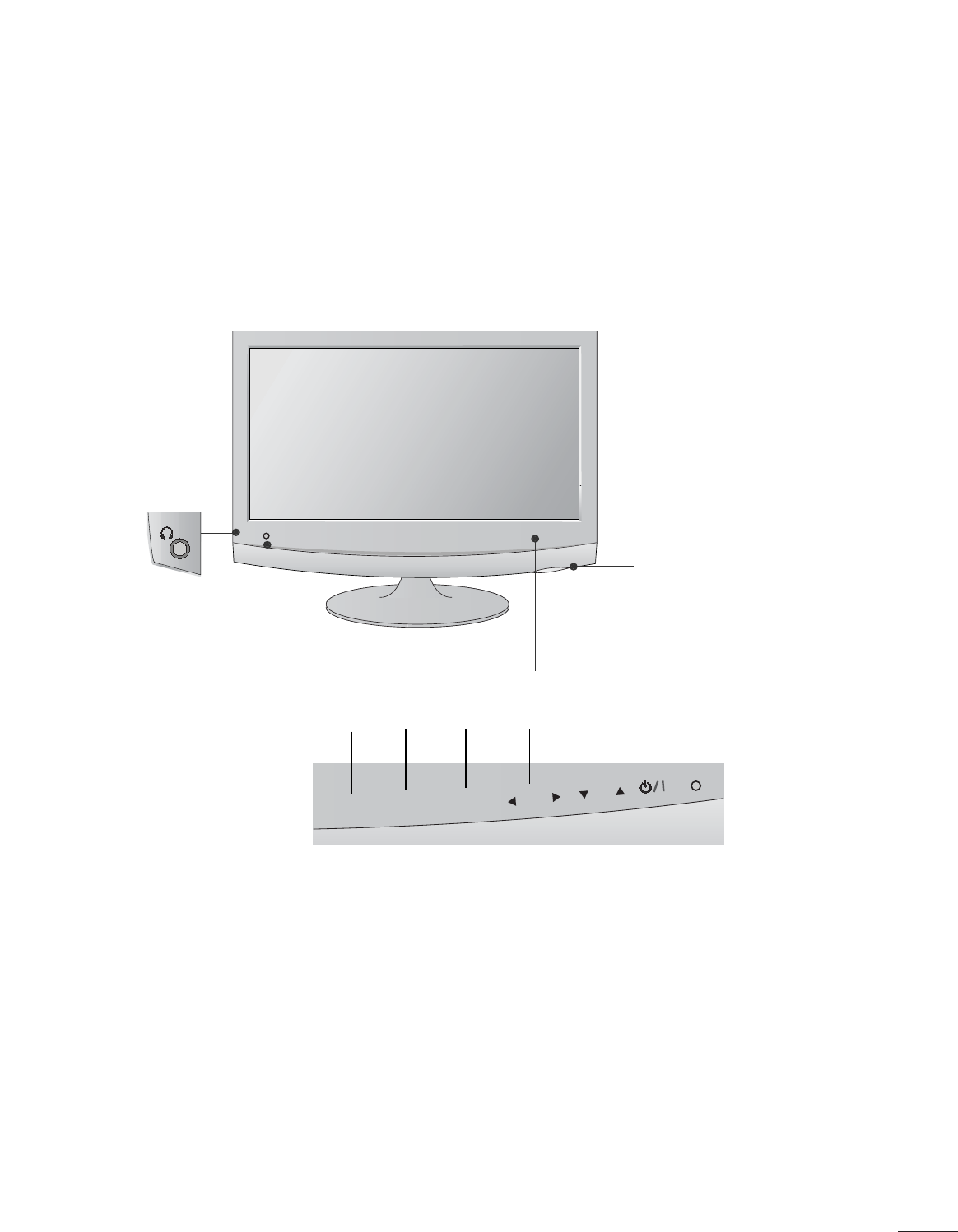
FRONT PANEL CONTROLS
■
This is a simplified representation of the front panel. The image shown may be somewhat different from your
set.
INPUT
Button
INPUT
MENU
CH
VOL
ENTER
MENU
Button
OK
Button
VOLUME
Buttons
CHANNEL
Buttons
Power
Button
Headphone
Jack
IR receiver
(Remote controller
receiver)
Light Sensor
This is lens for light sensor
select outside luminance,
when setting AUTO
BRIGHT ON.
Power Indicator
illuminates blue when the
set is switched on.
Note:You can adjust
Power indicator in the
OPTION menu.
2
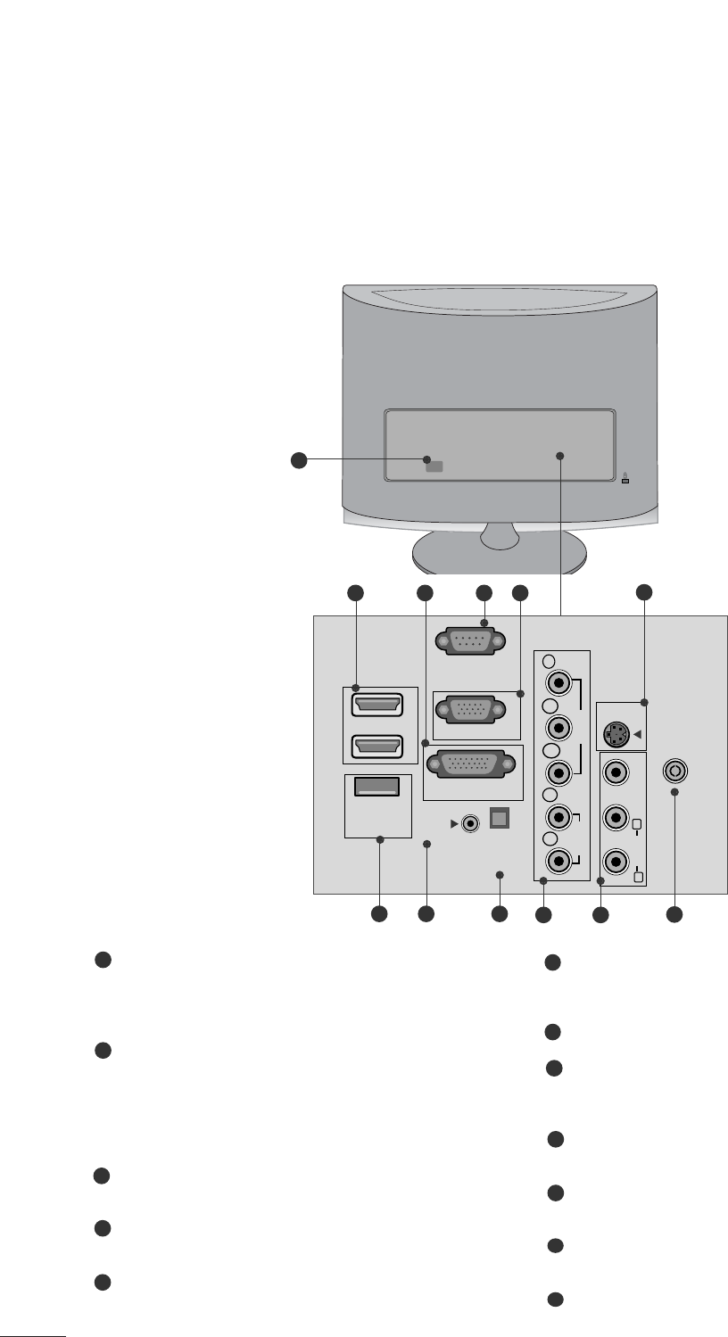
PREPARATION
BACK PANEL INFORMATION
■
This is a simplified representation of the back panel. The image shown may be somewhat different from your
set.
VIDEO
COMPONENT
IN
AV-IN
VIDEO
S-VIDEO
AUDIO
Y
P
B
P
R
L
R
RS-232C IN
(CONTROL & SERVICE)
SERVICE
ONLY
RGB IN (PC)
DVI-D IN (PC)
HDMI IN
1
2
OPTICAL
DIGITAL
AUDIO OUT
AUDIO IN
(RGB/DVI)
ANTENNA/
CABLE IN
AUDIO
(MONO)
LR
2
910 11
1
87 12
56
3 4
Power Cord Socket
This set operates on AC power. The voltage is indicated
on the Specifications page. Never attempt to operate
the set on DC power.
HDMI Input
High definition inputs. These two inputs accept TV
Video, not PC Video. They also accept TV Video from a
DVI connection when using an adapter. The HDMI
inputs support video and audio. When using an adapter
for DVI, they only accept video.
DVI-D Input
Digital PC input.
RS-232C IN (CONTROL & SERVICE) PORT
Serial port used for external control or service.
RGB INPUT (PC)
Analog PC input. Also known as VGA.
S-Video Input
Standard definition (480i), but better quality than
standard A/V input.
SERVICE ONLY PORT
RGB/DVI Audio Input
This is the audio input for the RGB and DVI-D video
inputs.
Optical Digital Audio Out
Use this to export audio to an external amplifer.
Component Input
High definition analog input.
Audio/Video Input
Standard definition input.
Antenna Input
Connect over-the-air or cable signals to this jack.
1
2
3
4
5
7
6
8
9
10
11
12
3
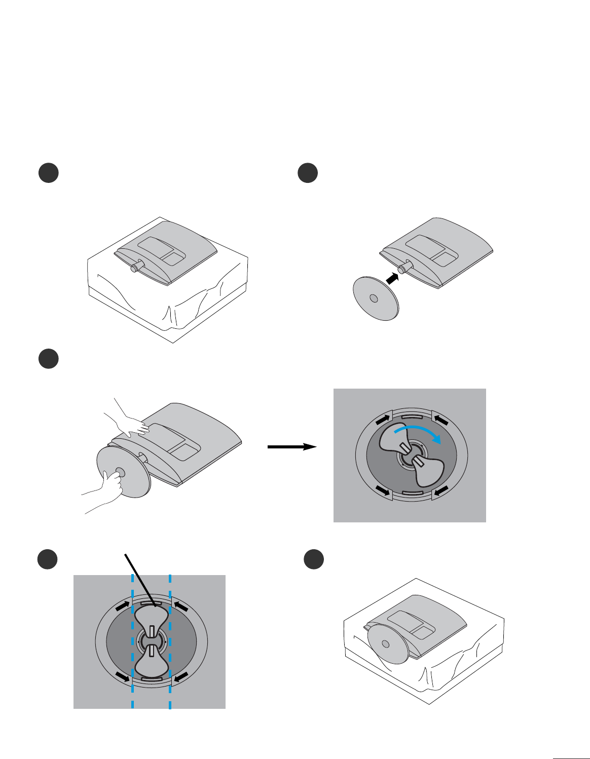
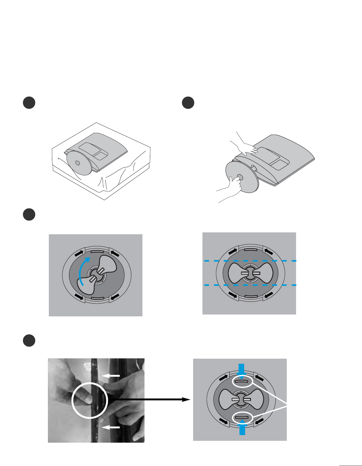
PREPARATION
STAND INSTALLATION
■
The image shown may be somewhat different from your set.
12
3
Carefully place the product screen side down on a
cushioned surface that will protect product and
screen from damage.
Insert the stand base into the product
Turn the Stand Base Lock through 90°to fix the Stand Base to the Stand Body.
Base Lock
<Locked>
4 5
O
P
E
N
O
P
E
N
O
P
E
N
O
P
E
N
<M2262D/M2362D>
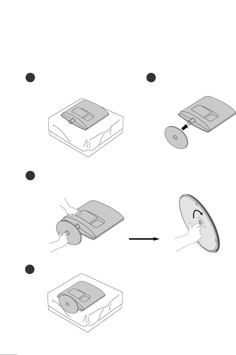
4
PREPARATION
STAND INSTALLATION
■
The image shown may be somewhat different from your set.
12
3
Carefully place the product screen side down on a
cushioned surface that will protect product and
screen from damage.
Insert the stand base into the product
Attach the monitor to the Stand Base by turning the screw to the right.
*Turn the screw by using the screw handle
4
<M2762D>
5
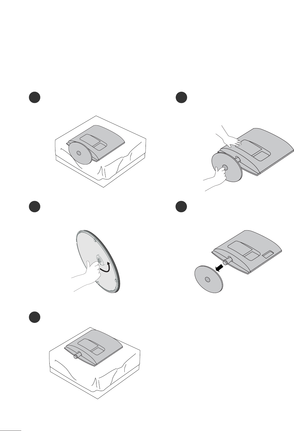
PREPARATION
DETACHING STAND
■
The image shown may be somewhat different from your monitor.
12
3
4
Place the set screen side down on a cushion or
soft cloth.
Detach the monitor to the Stand Base by turn-
ing the screw to the left.
Turn the Stand Base Lock through 90°to separate the Stand Base from the Stand Body.
Pushing Latch inside, Take the stand base from stand body.
O
P
E
N
O
P
E
N
O
P
E
N
O
P
E
N
O
P
E
N
O
P
E
N
Latch
<M2262D/M2362D>
6
PREPARATION
DETACHING STAND
■
The image shown may be somewhat different from your monitor.
12
3
5
Place the set screen side down on a cushion or
soft cloth.
Detach the monitor to the Stand Base by
turning the screw to the left.
Turn the screw by using the screw handle. 4Pull the stand base.
<M2762D>
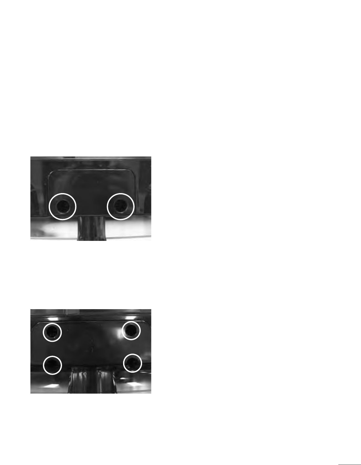
7
PREPARATION
<M2762D>
DETACHING STAND BODY
1. Remove the screw 4 point.
2. Pull the stand body.
1. Remove the screw 2 point.
2. Pull the stand body.
■
The image shown may be somewhat different from your set.
■
Remove the Stand Body in the same way as the following when using it as a Wall Hook.
<M2262D/M2362D>
8
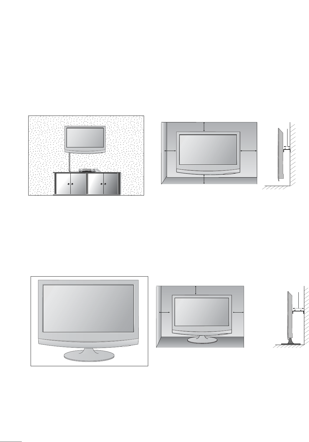
PREPARATION
DESKTOP PEDESTAL INSTALLATION
For proper ventilation, allow a clearance of 4 inches on each side and from the wall.
WALL MOUNT: HORIZONTAL INSTALLATION
For proper ventilation, allow a clearance of 4 inches on each side and from the wall. Follow the instructions
included with the wall mount.
4 inches
4 inches
4 inches
4 inches
4 inches
4 inches
4 inches 4 inches
4 inches
9
PREPARATION
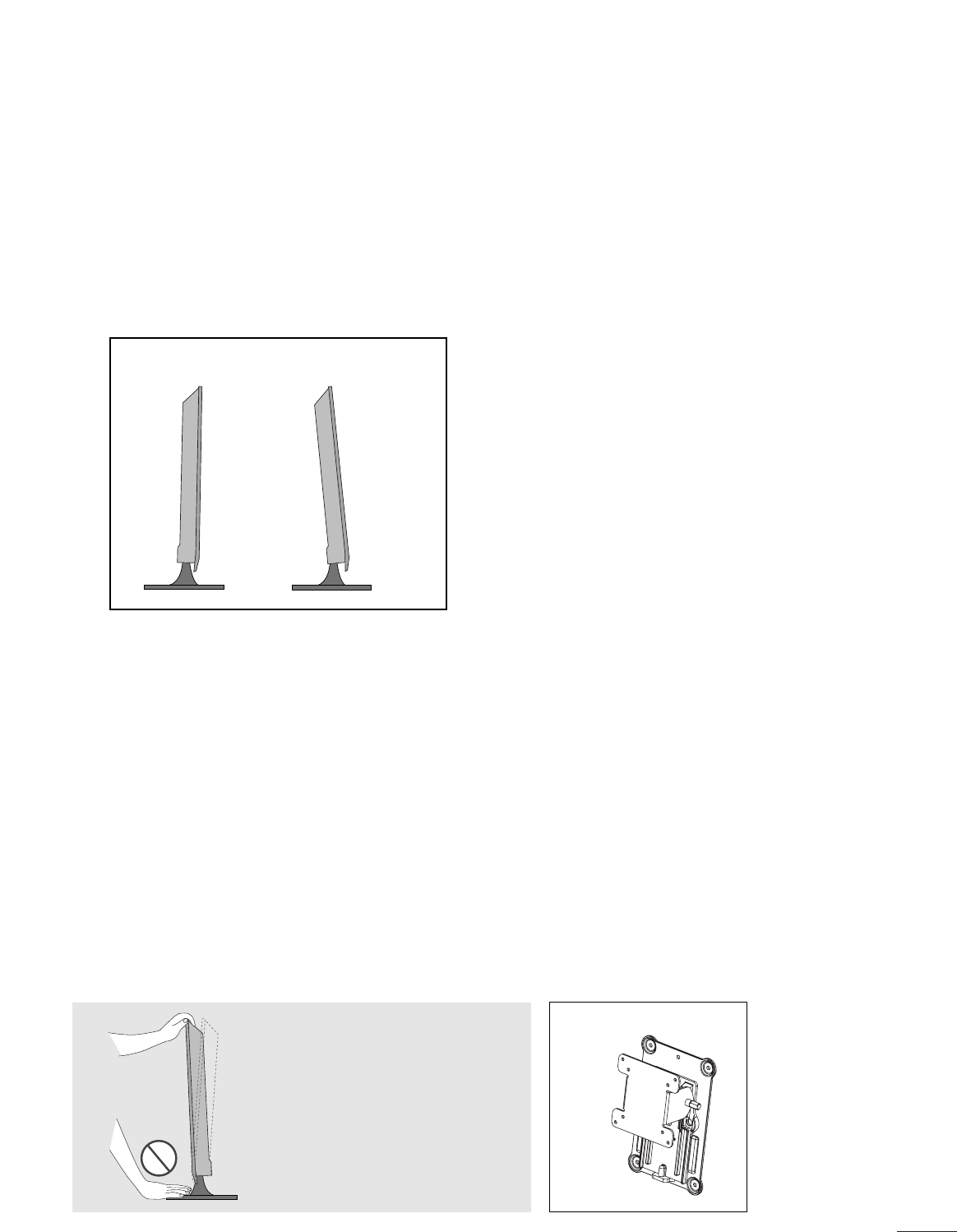
POSITIONING YOUR DISPLAY
■
The image shown may be somewhat different from your set.
Adjust the position of the panel in various ways for maximum comfort.
• Tilt range
LOCATION
Position your set so that no bright light or sunlight falls directly onto the screen. Care should be taken not to expose
the set to any unnecessary vibration, moisture, dust or heat. Also, ensure that the set is placed in a position to allow a
free flow of air. Do not cover the ventilation openings on the back cover.
If you intend to mount the set to a wall, attach the wall mounting interface (optional parts) to the back of the set.
When you install the set using the wall mounting interface (optional parts), attach it carefully so it will not drop.
- Be sure to use screws and a wall mount that meet VESA standards.
- Using screws longer than those recommended might damage the product.
- Using screws that do not meet VESA standards might either damage the product or result in it coming away from the
wall. We will not be held responsible for any damage resulting from failure to follow these instructions.
< Screw Mounting Interface Dimension >
M2262D/M2362D : 100mm x 100mm hole spacing
M2762D : 200mm x 100mm hole spacing
* Wall mount interface(LG) : RW120
Warning:
When adjusting the angle of the
screen, do not put your finger(s)in
between the head of the monitor
and the stand body. You can hurt
your finger(s).
RW120
-5
°
15
°
10
PREPARATION
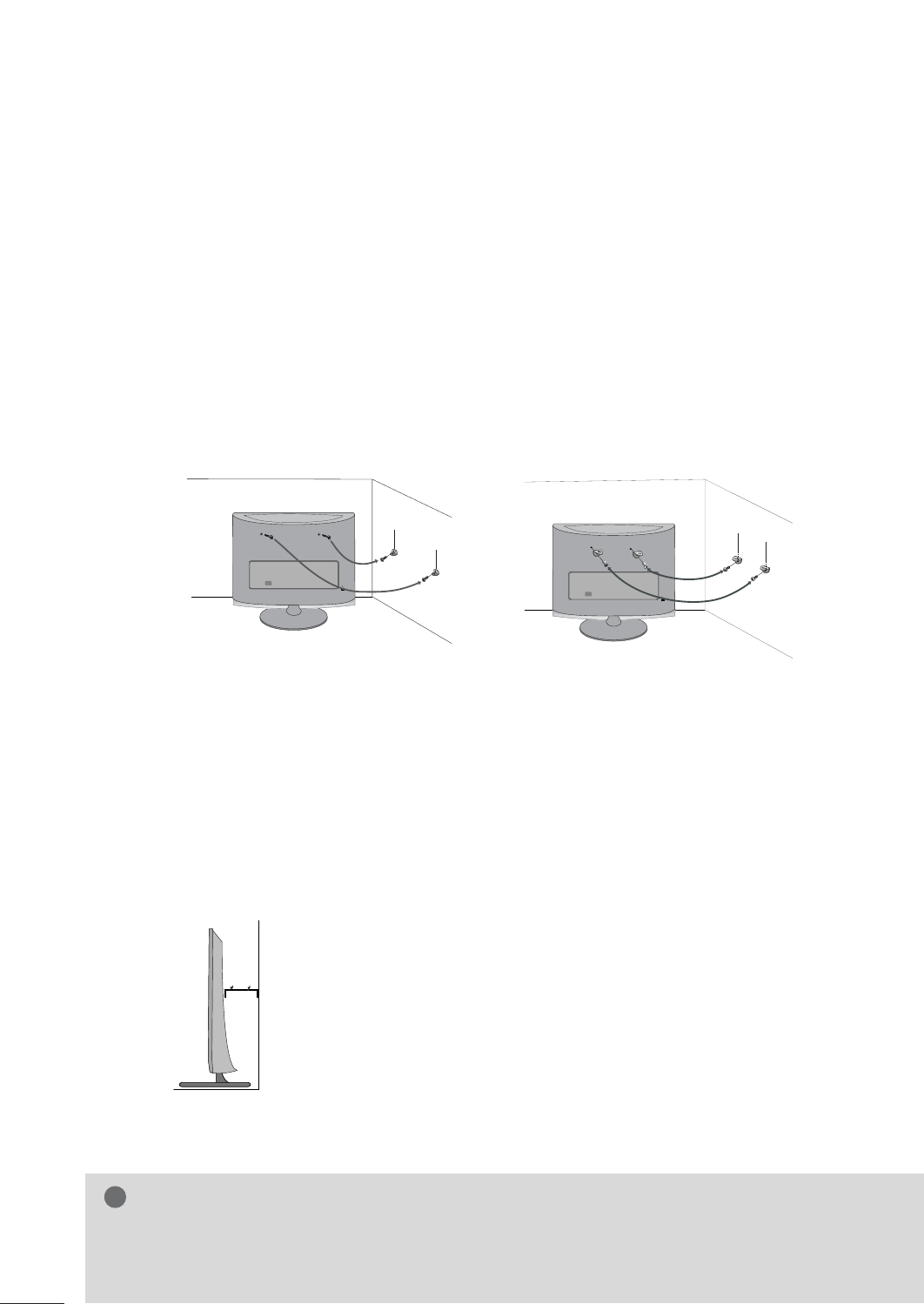
SECURING THE SET TO THE WALL TO PREVENT FALLING
WHEN THE SET IS USED ON A STAND
We recommend that you set up the set close to a wall so it cannot fall over if pushed backwards.
Additionally, we recommend that the set be attached to a wall so it cannot be pulled in a forward direction,
potentially causing injury or damaging the product.
Caution: Please make sure that children don’t climb on or hang from the set.
■Insert the eye-bolts (or set brackets and bolts) to tighten the product to the wall as shown in the picture.
*If your product has the bolts in the eye-bolts position before inserting the eye-bolts, loosen the bolts.
* Insert the eye-bolts or set brackets/bolts and tighten them securely in the upper holes.
Secure the wall brackets with the bolts (sold separately) to the wall. Match the height of the bracket that is
mounted on the wall to the holes in the product.
Ensure the eye-bolts or brackets are tightened securely.
■Use a sturdy rope or cord (sold separately) to tie the product. It is
safer to tie the rope so it becomes horizontal between the wall and the
product.
■
Image shown may differ from your set.
GWhen moving the set, undo the cords first.
GUse a platform or cabinet strong enough and large enough to support the size and weight of the set.
GTo use the set safely make sure that the height of the bracket on the wall and the one on the set are the same.
NOTE
!
11
PREPARATION
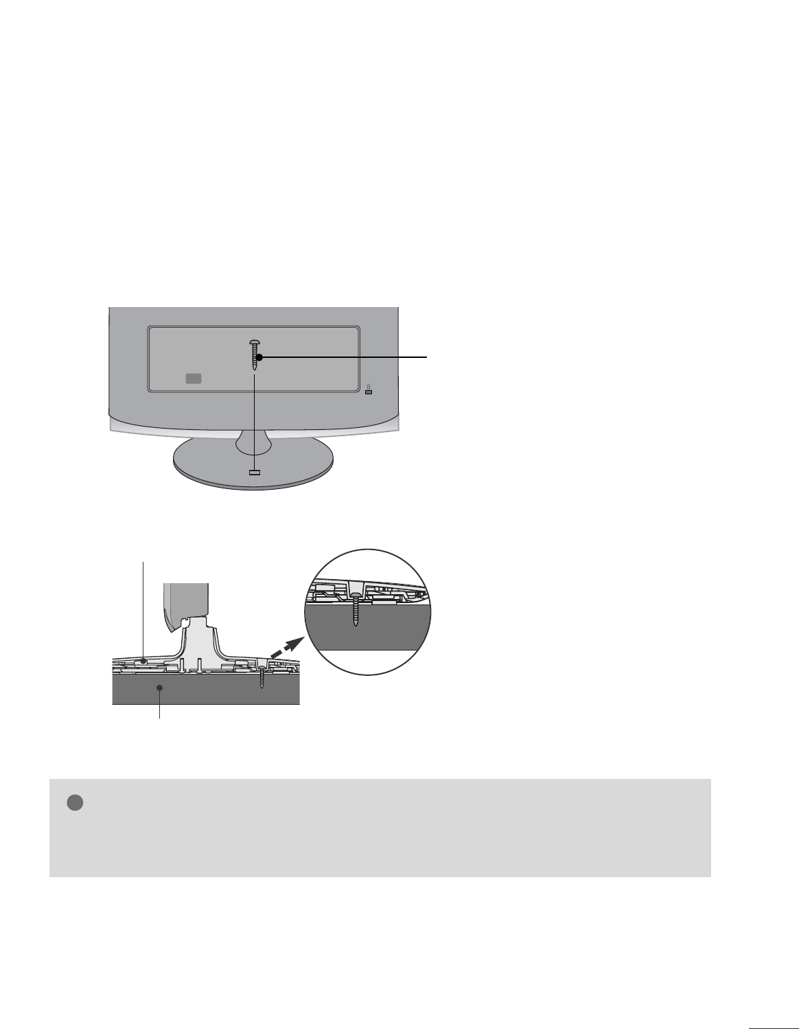
ATTACHING THE TV TO A DESK (Only M2762D)
The TV must be attached to desk so it cannot be pulled in a forward/backward direction,potentially causing
injury or damaging the product.Use only an attached screw.
■
Image shown may differ from your set.
Desk
Stand
WARNING
!
GTo prevent TV from falling over,the TV should be securely attached to the floor/wall per installation
instructions. Tipping,shaking, or rocking the machine may cause injury.
1-Screw
(provided as parts of the product)
12
PREPARATION
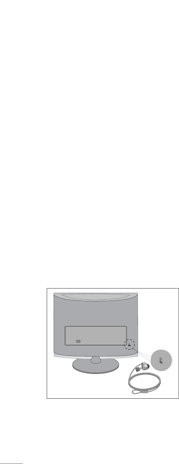
KENSINGTON SECURITY SYSTEM
- The product is equipped with a Kensington Security System connector on the back panel. Connect the
Kensington Security System cable as shown below.
- For detailed installation and use of the Kensington Security System, refer to the user’s guide provided with the
Kensington Security System.
For further information, contact http://www.kensington.com, the internet homepage of the Kensington
company. Kensington sells security systems for expensive electronic equipment such as notebook PCs and
LCD projectors.
NOTE
- The Kensington Security System is an optional accessory available at most electronics stores.
NOTES
a. If the product feels cold to the touch, there may be a small “flicker” when it is turned on.
This is normal, there is nothing wrong with product.
b. Some minute dot defects may be visible on the screen, appearing as tiny red, green, or blue spots. However,
they have no adverse effect on the monitor's performance.
c. Avoid touching the LCD screen or holding your finger(s) against it for long periods of time.
ANTENNA/
CABLE IN
ANTENNA/
CABLE IN
13
PREPARATION
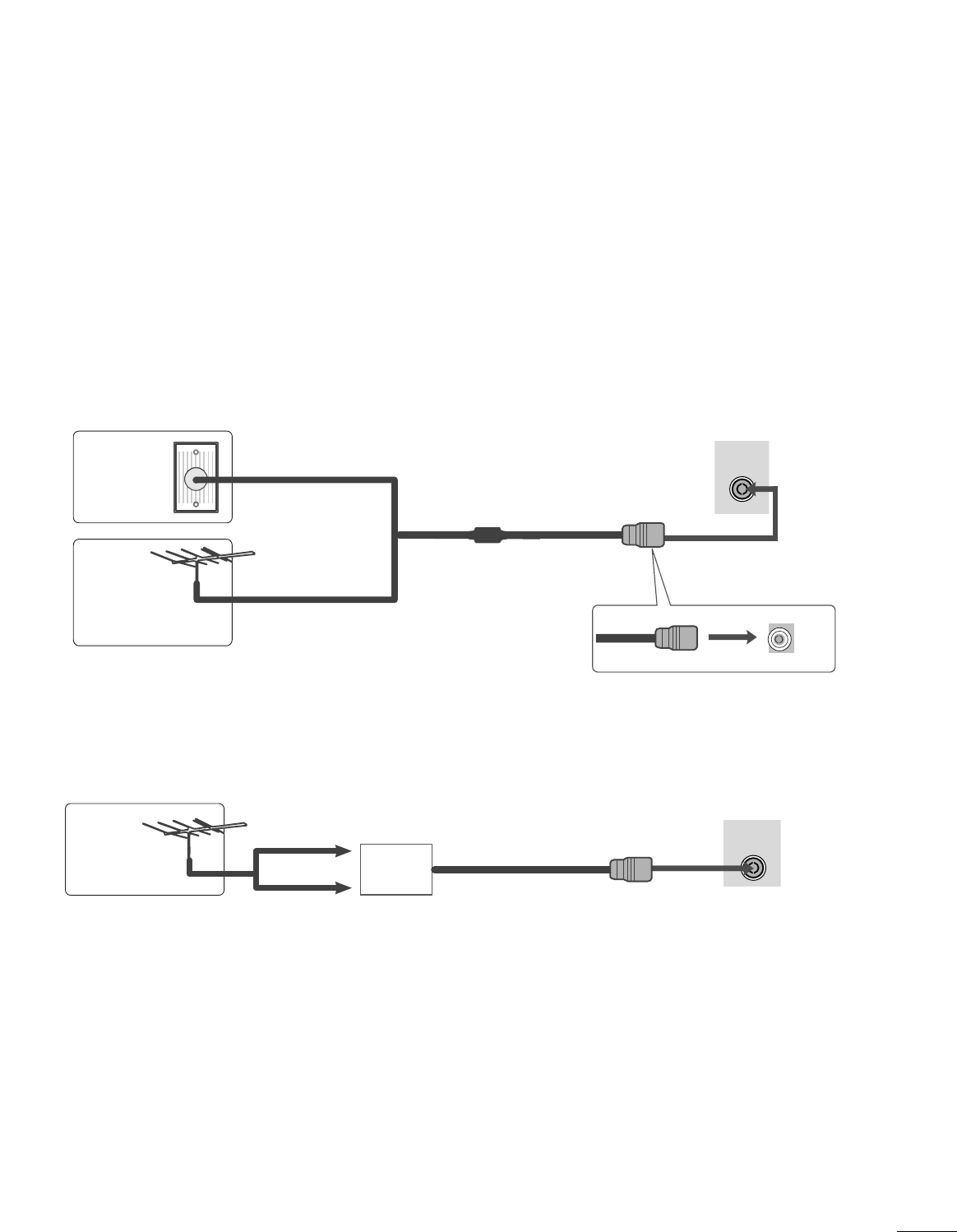
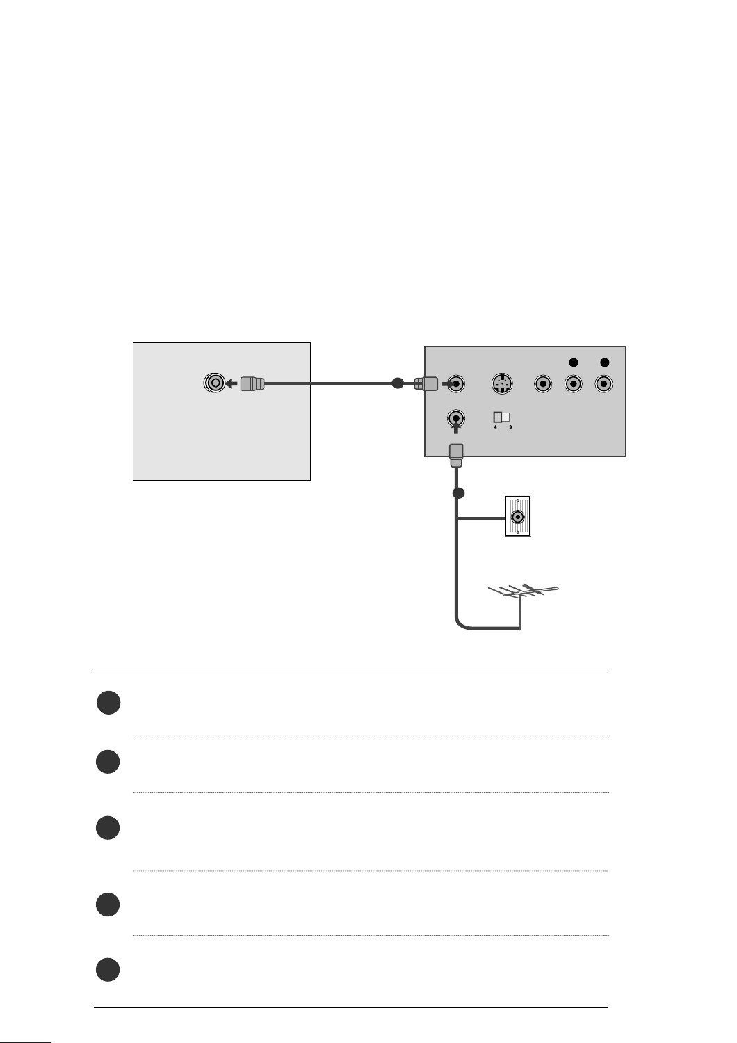
■For optimum picture quality, adjust antenna direction.
■An antenna cable and converter are not supplied.
■To prevent equipment damage, never plug in any power cords until you have finished connecting all equipment.
Multi-family Dwellings/Apartments
(Connect to wall antenna socket)
Single-family Dwellings /Houses
(Connect to wall jack for outdoor antenna)
Outdoor
Antenna
(VHF, UHF)
Wall
Antenna
Socket
RF Coaxial Wire (75 ohm)
ANTENNA CONNECTION
Antenna
UHF
VHF
■In poor signal areas, to get better picture quality, install a signal amplifier to the antenna as shown above.
■If signal needs to be split for two TVs, use an antenna signal splitter for connection.
Signal
Amplifier
14
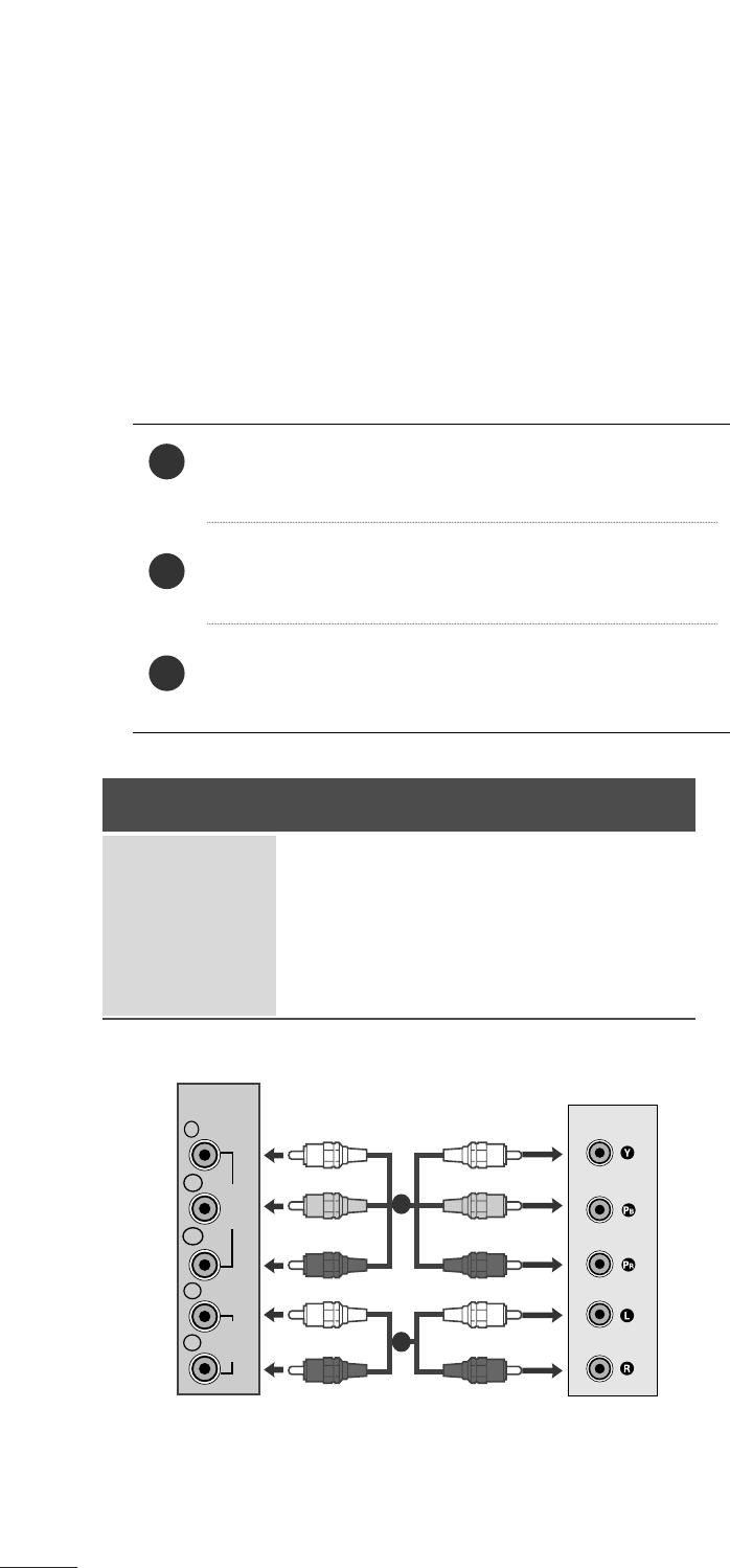
EXTERNAL EQUIPMENT SETUP
Connect the SET-TOP outputs to the COMPONENT IN
VIDEO sockets (Y PBPR) on the set.
Connect the audio cable from the SET-TOP to COMPO-
NENT IN AUDIO sockets of the set.
Press the INPUT button to select Component.
2
3
1
HD RECEIVER SETUP
■To prevent the equipment damage, never plug in any power cords until you have finished connecting all equipment.
■
The image shown may be somewhat different from your set.
When connecting with a component cable
Signal
480i
480p
576p
720p/1080i
1080p
Component
Yes
Yes
No
Yes
Yes
HDMI
No
Yes
Yes
Yes
Yes
VIDEO
COMPONENT
IN
AUDIO
Y
P
B
P
R
L
R
1
2
15
EXTERNAL EQUIPMENT SETUP
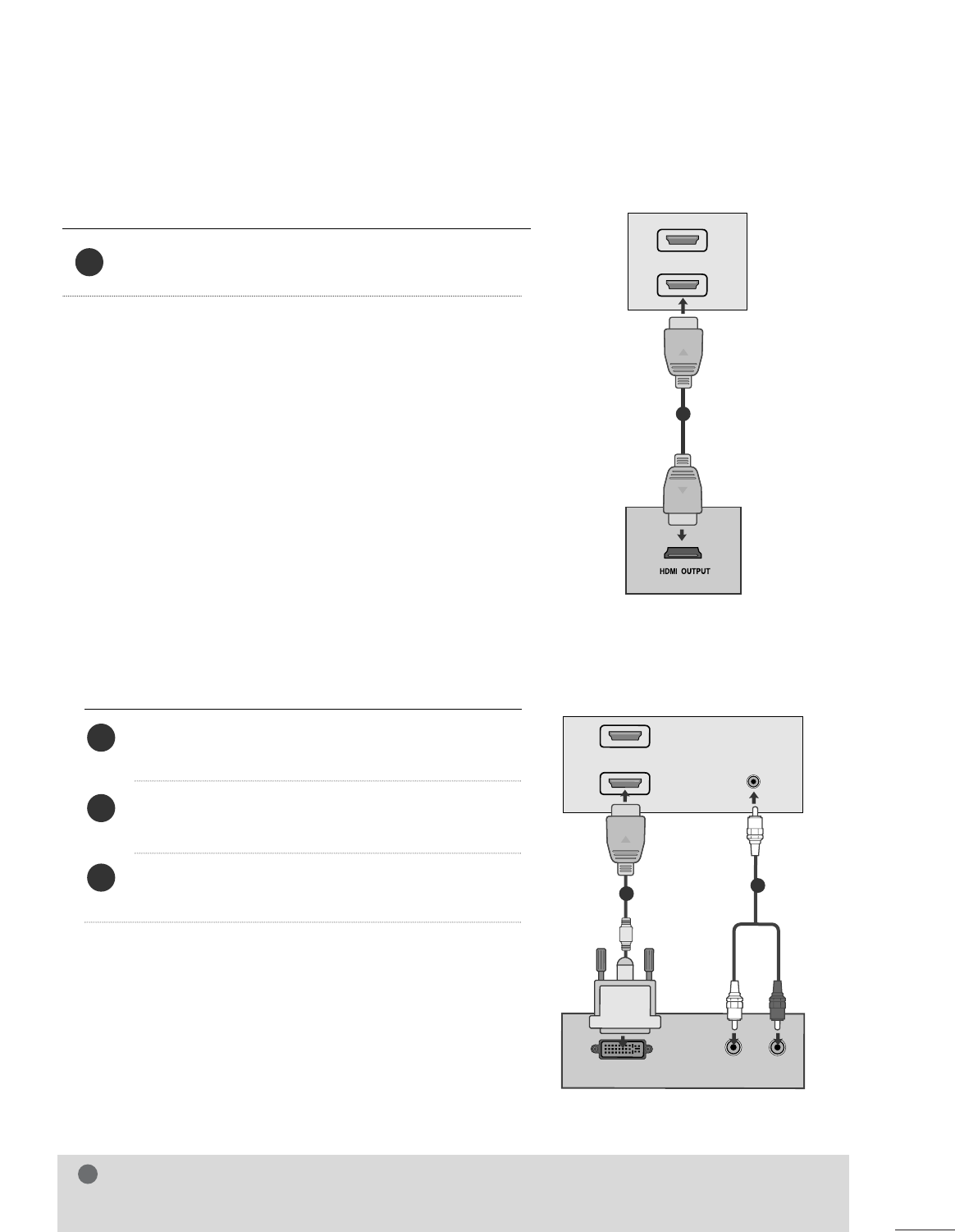
When connecting with a HDMI
Connect the HDMI output of the digital set-top box to the
HDMI IN jack on the set.
1
Connect the digital set-top box to HDMI IN jack on
the set.
Connect the audio output of the digital set-top box to
the AUDIO IN (RGB/DVI) jack on the set.
Turn on the digital set-top box. (Refer to the owner’s
manual for the digital set-top box.)
2
3
1
When connecting with a HDMI to DVI cable
HDMI IN
1
2
1
DVI OUTPUT
AUDIO
R
L
AUDIO IN
(RGB/DVI)
HDMI IN
1
2
12
NOTE
!
GHDMI Input does not support PC mode. If it is connected PC, the screen may not display properly.
16
EXTERNAL EQUIPMENT SETUP
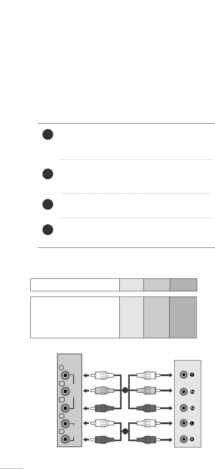
DVD SETUP
When connecting with a component cable
Component Input ports
To get better picture quality, connect a DVD player to the component input ports as shown below.
Component ports on the set
YPBPR
Video output ports
on DVD player
Y
Y
Y
Y
PB
B-Y
Cb
Pb
PR
R-Y
Cr
Pr
Connect the video output sockets (Y PBPR) of the DVD
to the COMPONENT IN VIDEO sockets (Y PBPR) of
the set.
Connect the audio cable from the DVD to COMPO-
NENT IN AUDIO sockets of the set.
Press the INPUT button to select Component.
Press the PLAY button on the DVD.
The DVD playback picture appears on the screen.
2
3
4
1
VIDEO
COMPONENT
IN
AUDIO
Y
P
B
P
R
L
R
1
2
17
EXTERNAL EQUIPMENT SETUP
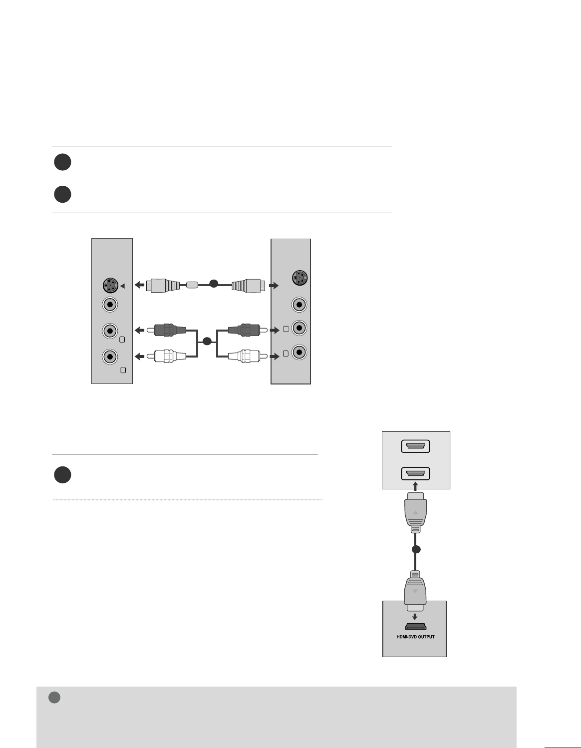
When connecting HDMI cable
Connect the HDMI output of the DVD to the
HDMI IN jack on the set.
1
GHDMI supports video and audio. You do not need to connect a sperate audio cable.
GIf the DVD player does not support Auto HDMI, you need to set the DVD output resolution appropriately.
NOTE
!
HDMI IN
1
2
1
When connecting S-Video
Connect the S-Video output of the DVD to the S-Video in put on the set.
Connect the audio output of the DVD to the AUDIO in put on the set.
1
2
VIDEO AUDIO
(MONO)
S-VIDEO
LR
AV-IN
VIDEO
S-VIDEO
LR
1
2
18
EXTERNAL EQUIPMENT SETUP
VCR SETUP
■To avoid picture noise (interference), leave an adequate distance between the VCR and the set.
■If a user uses 4:3 picture format for a long time, an afterimage may remain on the sides of the screen for a
short time.
OUTPUT
SWITCH
ANT IN
R
S-VIDEO VIDEO
ANT OUT L
ANTENNA/
CABLE IN
Wall Jack
Antenna
1
2
When connecting with an antenna
Connect the RF out socket of the VCR to the antenna socket of the set.
Connect the antenna cable to the RF aerial in socket of the VCR.
Store the VCR channel on a desired channel number using the ‘Manual channel
tuning’ section.
Select the Channel number where the VCR channel is stored.
Press the PLAY button on the VCR.
1
2
3
4
5
19
EXTERNAL EQUIPMENT SETUP
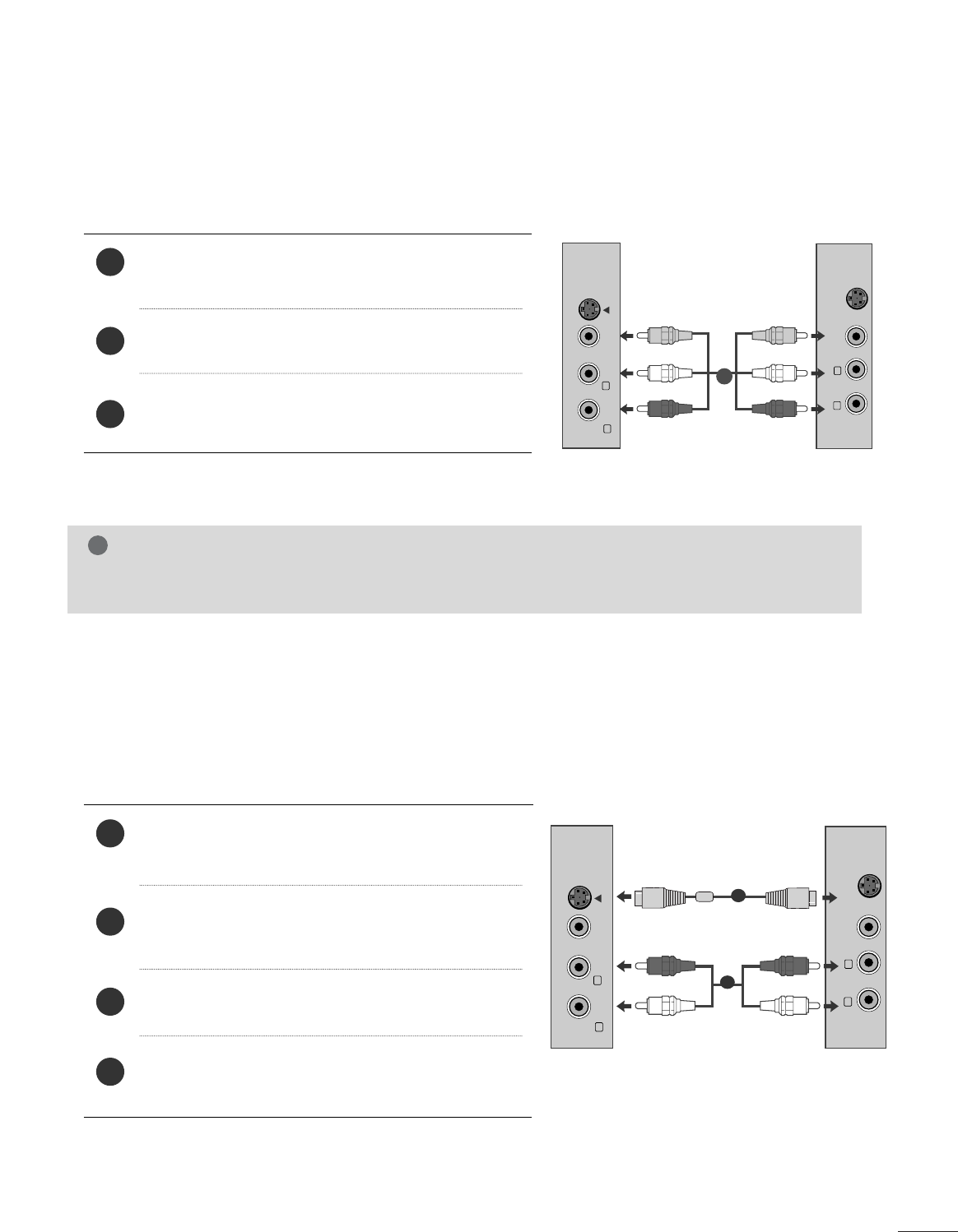
When connecting with a RCA cable
Connect the audio/video out sockets of the VCR to
AUDIO/VIDEO in sockets of the set.
Press the INPUT button to select AV.
Press the PLAY button on the VCR.
The VCR playback picture appears on the screen.
2
3
1
When connecting with an S-Video cable
Connect the S-Video socket of the VCR to the S-
VIDEO socket of the set.
Connect the audio cable from the S-VIDEO of the VCR
to the AUDIO sockets of the set.
Press the INPUT button to select AV.
Press the PLAY button on the VCR.
The VCR playback picture appears on the screen.
2
3
4
1
NOTE
!
GIf you have a mono VCR, connect the audio cable from the VCR to the AUDIO L/MONO jack of the set.
VIDEO AUDIO
(MONO)
S-VIDEO
LR
AV-IN
VIDEO
S-VIDEO
LR
VIDEO AUDIO
(MONO)
S-VIDEO
LR
AV-IN
VIDEO
S-VIDEO LR
1
2
1
20
EXTERNAL EQUIPMENT SETUP
PC SETUP
This product provides Plug and Play capability, meaning that the PC adjusts automatically to the set's settings.
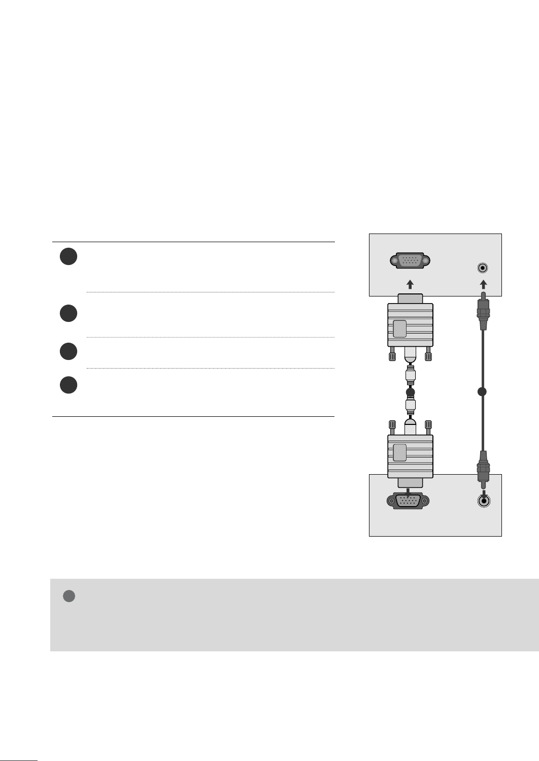
When connecting with a D-sub 15 pin cable
4
Connect the signal cable from the monitor output socket
of the PERSONAL COMPUTER to the PC input socket of
the set.
Connect the audio cable from the PC to the AUDIO IN
(RGB/DVI) sockets of the set.
Press the INPUT button to select RGB.
Switch on the PC, and the PC screen appears on the set.
The set can be operated as a PC monitor.
2
3
1
RGB OUTPUT AUDIO
AUDIO IN
(RGB/DVI)
RGB IN (PC)
12
NOTE
!
GUser must use shielded signal interface cables (D sub 15 pin cable, DVI cable) with ferrite cores to main-
tain standard compliance for the product.
21
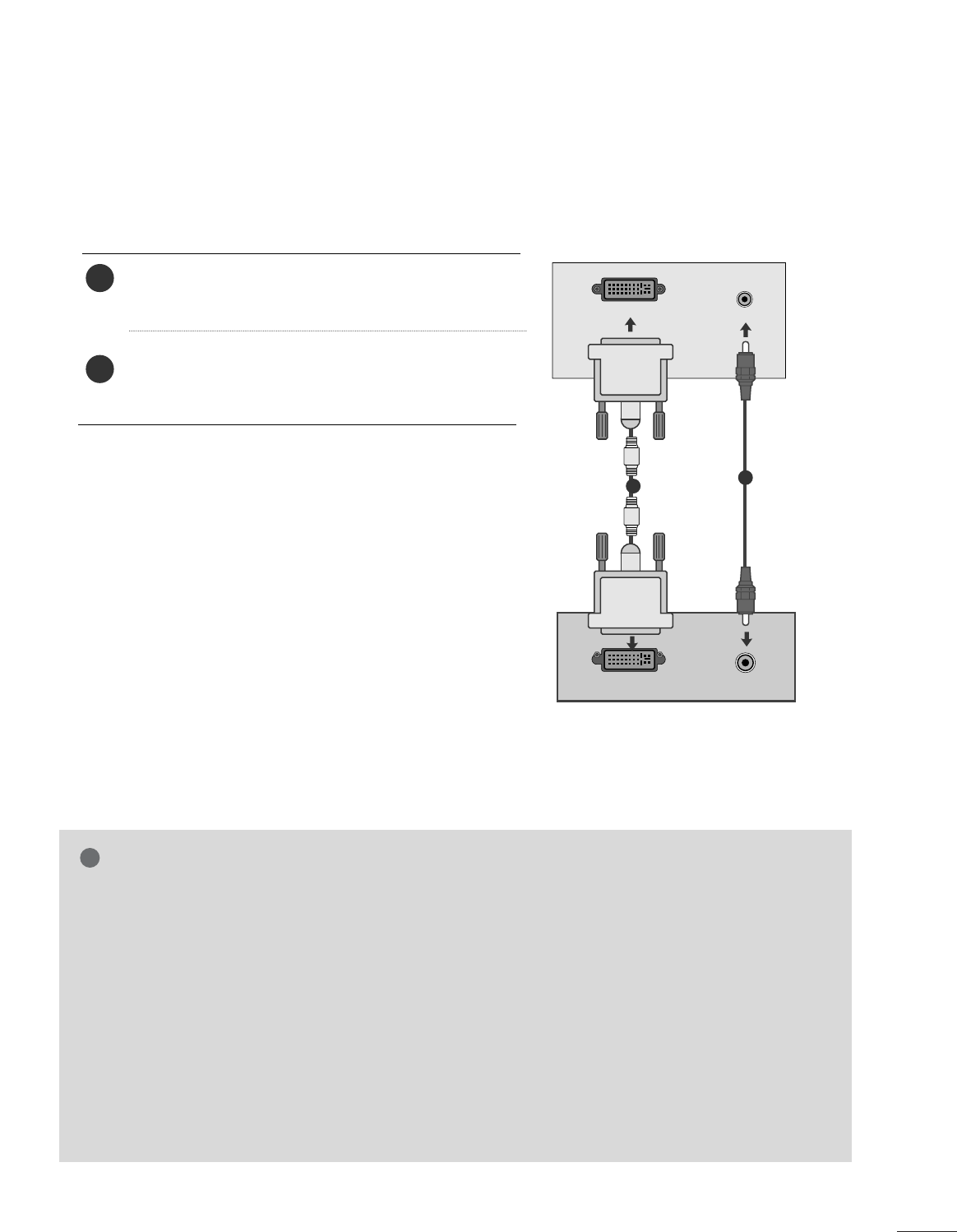
EXTERNAL EQUIPMENT SETUP
When connecting with a DVI cable
Connect the DVI output of the PC to the DVI-D IN
jack on the set.
Connect the audio cable from the PC to the AUDIO
IN (RGB/DVI) sockets of the set.
2
1
NOTE
!
G
If the set is cold, there may be a small “flicker” when the
set is switched on. This is normal, there is nothing
wrong with the set.
G
If possible, use the 1920x1080 @ 60 Hz video mode
to obtain the best image quality for your LCD monitor.
If used with other resolutions, some scaled or
processed pictures may appear on the screen. The set
has been preadjusted to the mode 1920x1080 @ 60
Hz.
G
Some dot defects may appear on the screen, like Red,
Green or Blue spots. However, this will have no impact
or effect on the monitor performance.
G
Do not press the LCD screen with your finger for a long
time as this may produce some temporary distortion
effects on the screen.
G
Avoid keeping a fixed image on the set’s screen for pro-
longed periods of time. The fixed image may become
permanently imprinted on the screen; use a screen
saver when possible.
AUDIO
DVI OUTPUT
AUDIO IN
(RGB/DVI)
DVI-D IN (PC)
12
22
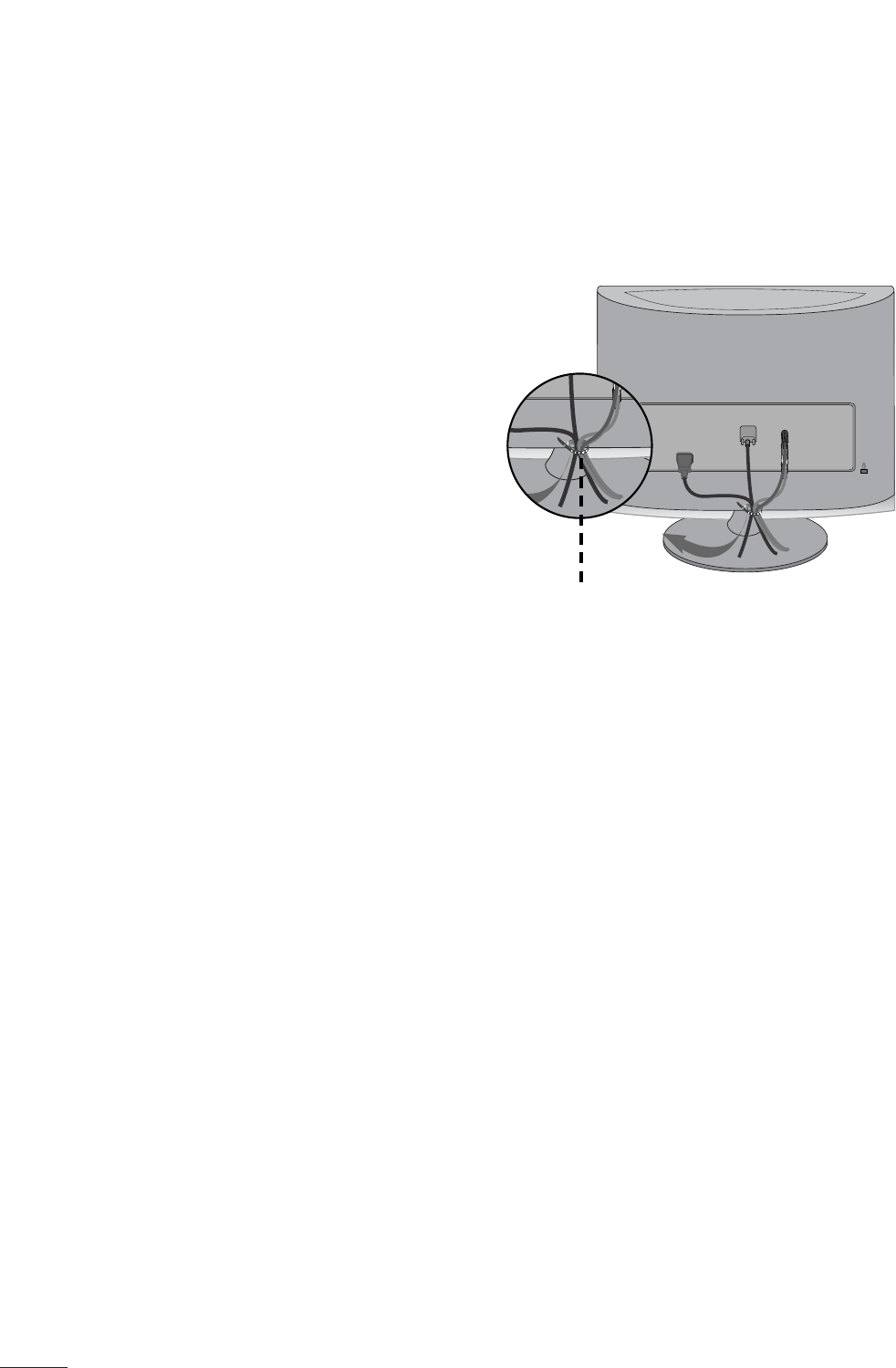
EXTERNAL EQUIPMENT SETUP
Tie cables together with a cable tie as shown in the
illustration.
Cable tie
R
R
BACK COVER FOR WIRE ARRANGEMENT
23
EXTERNAL EQUIPMENT SETUP
RGB/DVI[PC]
HDMI[DTV] supported mode
Resolution
640x480
800x600
720x400
1024 x 768
Horizontal
Frequency(kHz) Vertical
Frequency(Hz)
31.468 70
31.469 60
37.500 75
37.879 60
46.875 75
48.363 60
60.123 75
67.500 75
63.981 60
79.976 75
64.674 60
65.290 60
75.000 60
66.587 60
12 8 0 x 10 24
115 2 x 8 6 4
1680x1050
1920x1080
1600x1200
60
60
50
50
60
60
60
60
50
24
30
50
60
60
31.469
31.5
31.25
37.5
44.96
45
33.72
33.75
28.125
27
33.75
56.25
67.43
67.5
Resolution
720x480/60p
720x576/50p
1280x720/60p
1280x720/50p
Horizontal
Frequency(kHz) Vertical
Frequency(Hz)
1920x1080/60i
1920x1080/50i
1920x1080/24p
1920x1080/30p
1920x1080/50p
1920x1080/60p
25
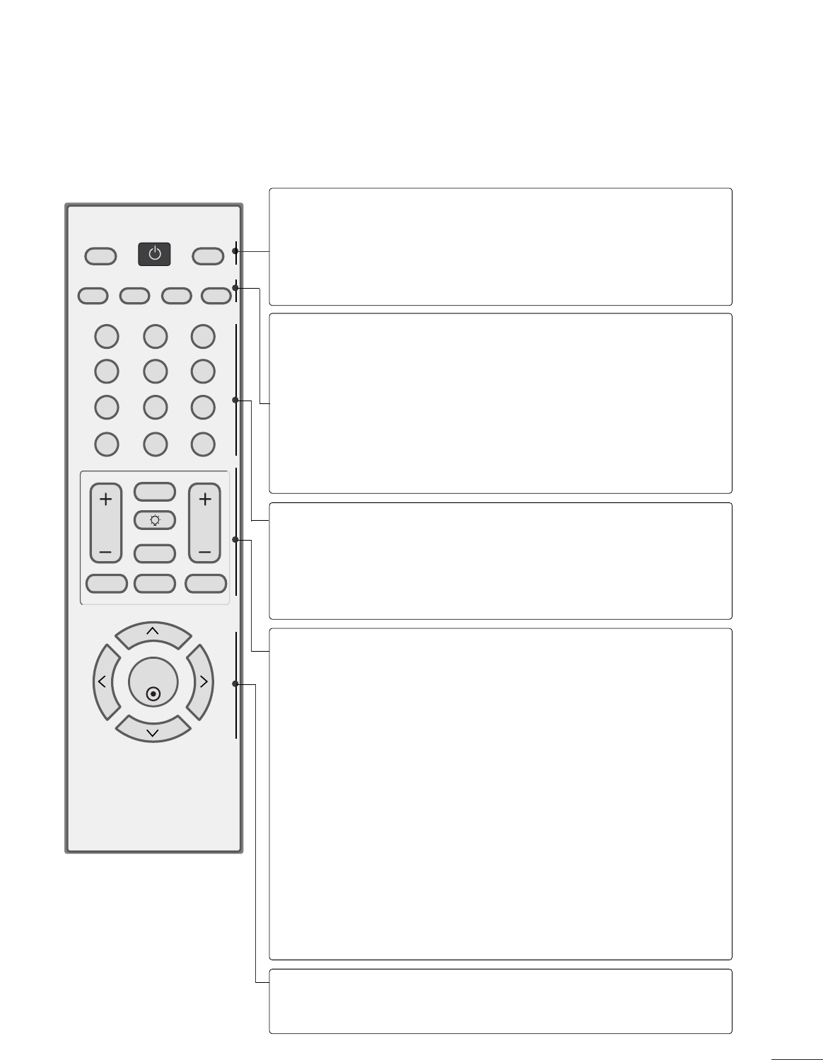
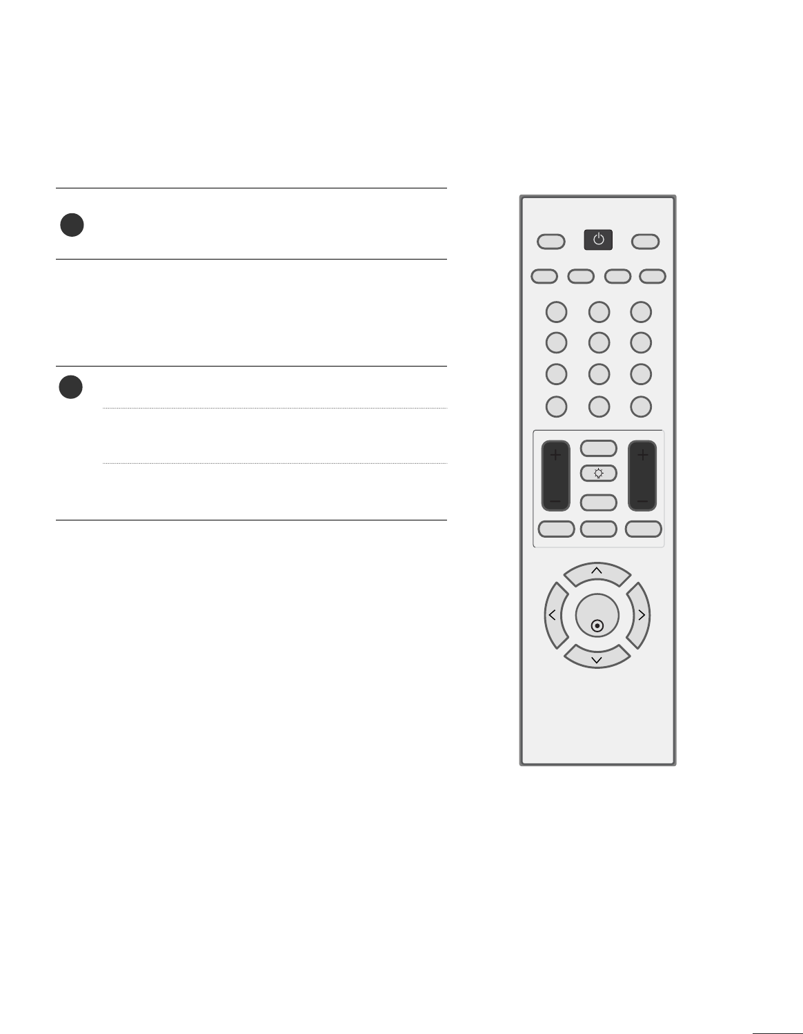
WATCHING TV / CHANNEL CONTROL
REMOTE CONTROL KEY FUNCTIONS
When using the remote control, aim it at the remote control sensor on the set.
123
456
78
0-
9
VOL CH
ENTER
POWER
MUTE
Q.MENU
MENU
FLASHBK
RETURN
FAV
PICTURE SOUND SAP
RATIO
TV/PC
INPUT
LIGHTING
POWER
TV/PC
INPUT
Turns your set on or off.
Selects TV or PC mode.
Switches the set on.
External input modes rotate in regular sequence
PICTURE
SOUND
SAP
RATIO
Toggles through the factory preset picture settings
depending on the viewing environment.
Toggles through preset sound settings.
* Toggles through Mono, Stereo, or SAP when using ana-
log audio.
* DTV mode: Changes the audio language.
Change the spect ratio.
NUMBER button
_(DASH)
FLASHBK
Used to enter a program number for multiple program
channels such s 2-1,2-2,etc.
Tunes to the last channel viewed.
VOLUME UP
/DOWN
FAV
LIGHTING
MUTE
CHANNEL
UP/DOWN
Q.MENU
MENU
RETURN
Increase/decrease the sound level.
Scroll through the programmed Favorite channels.
Press the Lighting button to turn the decoration light-
ing on/off.
Switch the sound on or off.
Select available channels.
Select the desired quick menu source.
Displays the main menu.
Allows the user to move return one step in an interac-
tive application or other user interaction function.
THUMBSTICK
(Up/Down/Left
Right/ENTER)
Navigate the on-screen menus and adjust the system set-
tings to your preference.
27
WATCHING TV / CHANNEL CONTROL
CHANNEL SELECTION
Press the CH + or -or NUMBER buttons to select a
programme number.
1
VOLUME ADJUSTMENT
Press the VOL + or -button to adjust the volume.
If you want to switch the sound off, press the MUTE
button.
You can cancel this function by pressing the MUTE,
VOL + or -.
123
456
78
0-
9
VOL CH
ENTER
POWER
MUTE
Q.MENU
MENU
FLASHBK
RETURN
FAV
PICTURE SOUND SAP
RATIO
TV/PC
INPUT
LIGHTING
1
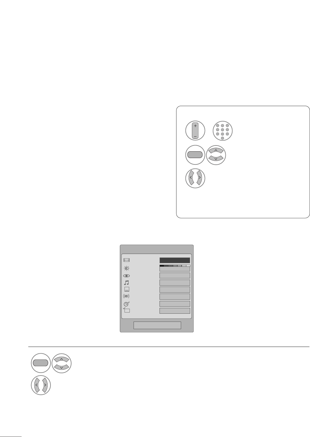
28
WATCHING TV / CHANNEL CONTROL
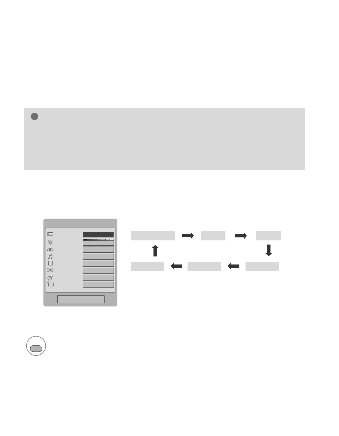
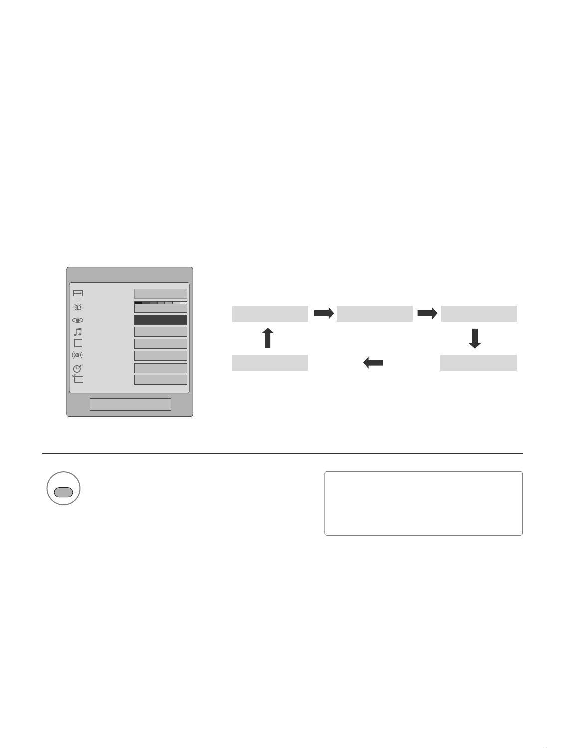
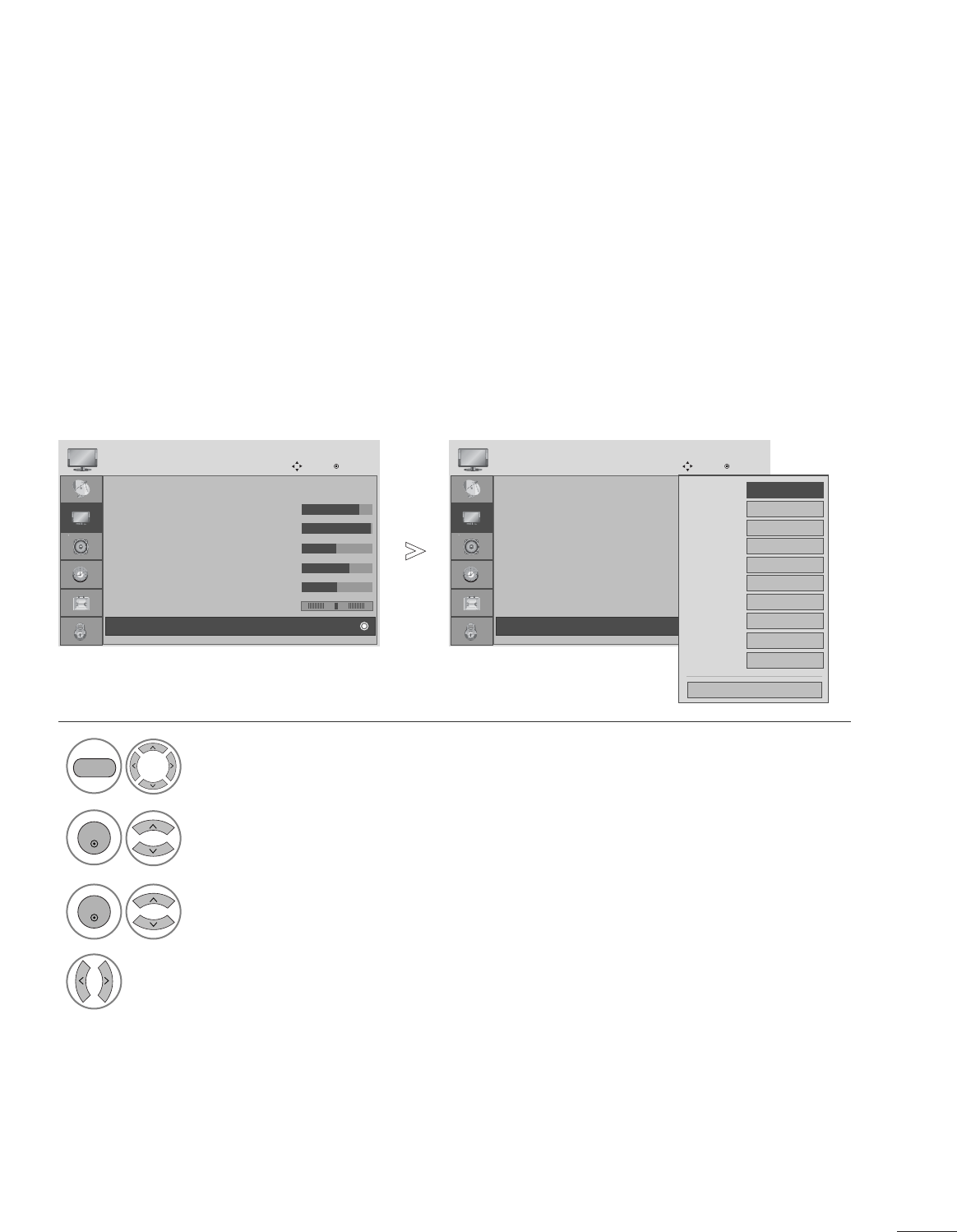
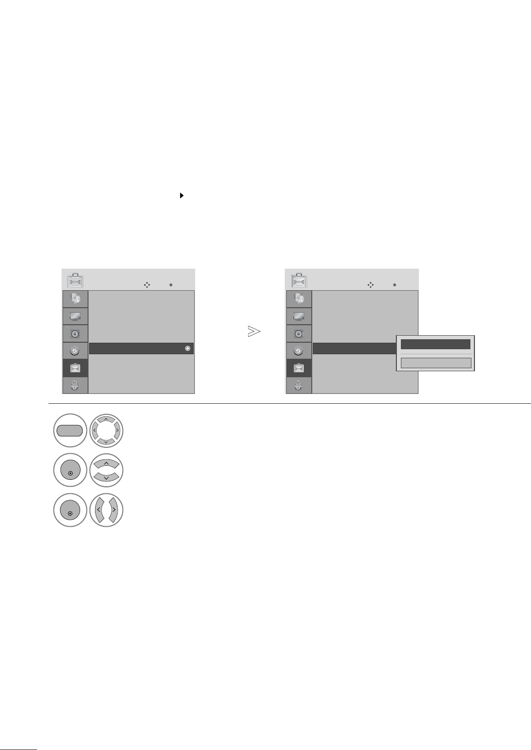
QUICK MENU / FAVORITE CHANNEL SETUP
Display each menu.
Make appropriate adjustments.
■Aspect Ratio: Selects your desired picture format.
■Backlight: Adjust the brightness of the LCD panel to
control the brightness of the screen and lower power
consumption.
■Picture Mode: Toggles through picture settings.
■Sound Mode: Toggles through sound settings.
■Caption: Select on or off.
■Multi Audio: Changes the audio language (Digital sig-
nal).
SAP: Selects MTS sound (Analog signal).
■Sleep Timer: Select the amount of time before your
TV turns off automatically.
■Del/Add/Fav: Select channel you want to add/delete or
add the channel to the Favorite List.
Your set’s OSD (On Screen Display) may differ slightly from what is shown in this manual.
Q.Menu (Quick Menu) is a menu of features which users might use frequently.
1
Q.MENU
2
Q.Menu
3
F16:9 G
Standard
Vivid
Off
English
Off
Add
Aspect Ratio
Backlight
Picture Mode
Sound Mode
Caption
Multi Audio
Sleep Timer
Del/Add/Fav
CH
Close
Favorite Channle Setup
Select Del/Add/Fav.
■ To tune to a favorite channel, press the FAV
(Favorite) button repeatedly.
2
Q.MENU
1
CH
1
456
78
0
9
23
Select your desired channel.or
3Select Favorite.
• Press the RETURN button to move to the previous menu screen.
29
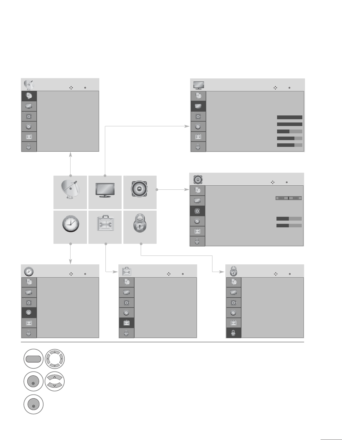
WATCHING TV / CHANNEL CONTROL
ON SCREEN MENUS SELECTION AND ADJUSTMENT
Your set's OSD (On Screen Display)may differ slightly from what is shown in this manual.
CHANNEL AUDIO
TIME OPTION LOCK
PICTURE
Auto tuning
Manual tuning
Channel Edit
CHANNEL
Move Enter
Auto Volume : Off
Balance 0
Sound Mode : Standard
• SRS TruSurround XT : Off
• Treble 50
• Bass 50
• Reset
TV Speaker : On
AUDIO
Move Enter
Clock
Off Time : Off
On Time : Off
Sleep Timer : Off
Auto Sleep : Off
TIME
Move Enter
Lock System : Off
Set Password
Block Channel
Movie Rating
TV Rating-Children
TV Rating-General
Downloadable Rating
Input Block
LOCK
Move Enter
Language : English
Input Label
Key Lock : Off
Caption : Off
Set ID : 1
Power Indicator : On
DDC-CI : On
RTC : On
OPTION
Move Enter
1
MENU
Display each menu.
2
ENTER
Select a menu item.
3Move to the pop up menu.
LR
ENTER
• Press the MENU button to close the menu window.
• Press the RETURN button to move to the previous menu screen.
Aspect Ratio : 16:9
Auto Bright : Off
Picture Mode : Vivid
• Backlight 100
• Contrast 100
• Brightness 50
• Sharpness 70
• Color 70
PICTURE
Move Enter
E
E
30
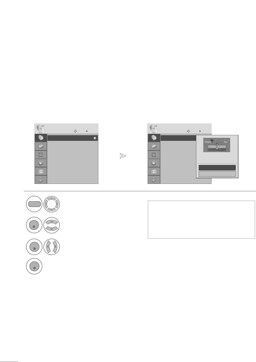
WATCHING TV / CHANNEL CONTROL
Use this to automatically find and store all available channels.
When you start auto programming in digital mode, all previously stored service information will be deleted.
AUTO CHANNEL TUNING
• Use the NUMBER buttons to input a 4-digit
password in Lock System ‘On’.
• If you wish to keep on auto tuning, select
YES using the F G button. Then, press the
OK button. Otherwise, select NO.
Select CHANNEL.
2
ENTER
Select Auto Tuning.
3Select Yes.
4Run Auto tuning.
1
MENU
ENTER
ENTER
• Press the MENU button to close the menu window.
• Press the RETURN button to move to the previous menu screen.
Auto tuning
Manual tuning
Channel Edit
CHANNEL
Move Enter
Auto tuning Auto tuning
Manual tuning
Channel Edit
CHANNEL
Move Enter
Auto tuning
Press ‘Yes’ button to begin
auto tuning.
Yes
No
31
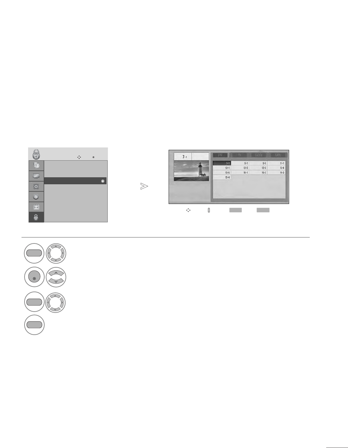
WATCHING TV / CHANNEL CONTROL
When selecting DTV or TV or CADTV or CATV input signal, you can view the on-screen signal
strength monitor to see the quality of the signal being received.
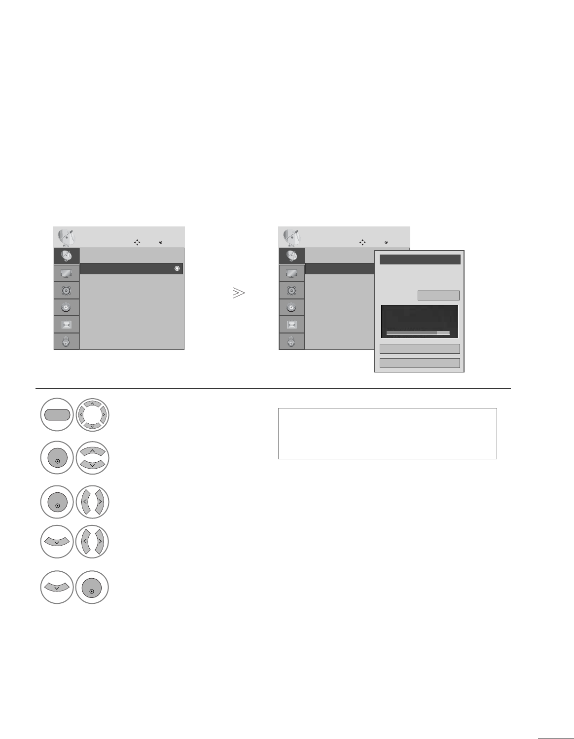
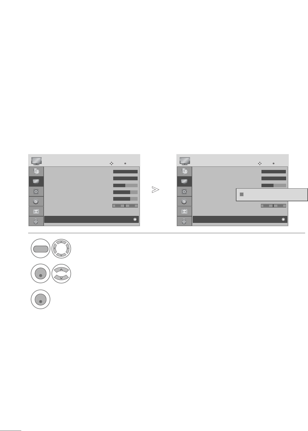
MANUAL TUNING
■A password is required to gain access to the
Manual Tuning menu if the Lock System is
turned on.
Select CHANNEL.
2Select Manual Tuning.
3Select D TV, T V, CADTV, or CATV.
4Select the channel you want to add or delete.
1
MENU
ENTER
ENTER
4Select Add or Delete.
ENTER
• Press the MENU button to close the menu window.
• Press the RETURN button to move to the previous menu screen.
Auto tuning
Manual tuning
Channel Edit
CHANNEL
Move Enter
Manual tuning
Auto tuning
Manual tuning
Channel Edit
CHANNEL
Move Enter
Manual tuning
Channel
Select channel type and
RF-channel number.
F
DTV
G
2
Close
Add
DTV 2-1
Bad Normal Good
32
WATCHING TV / CHANNEL CONTROL
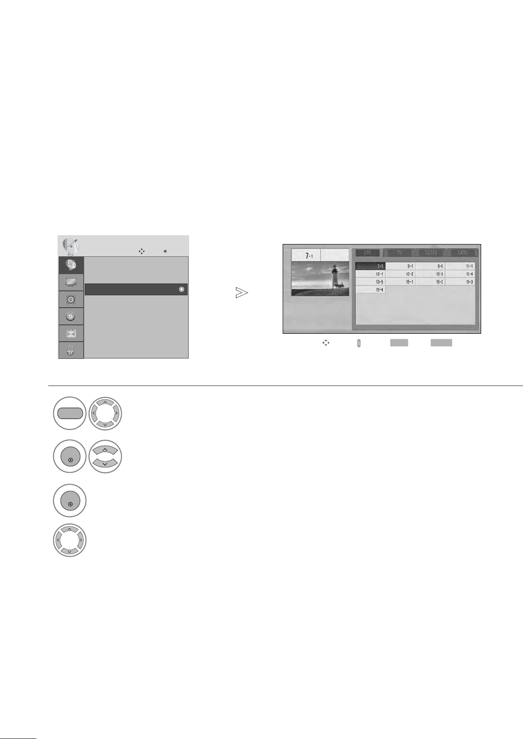
A custom list can be created by toggling each channel on or off with the ENTER button.
The channels in the Custom List are displayed in black and the channels deleted from the Custom List are displayed
in gray.
Once a channel is highlighted you can add or delete the channel by pressing the enter button.
CHANNEL EDIT
Select CHANNEL.
2Select Channel Edit.
3Select a Channel.
4Select channel you want to add or delete.
1
MENU
ENTER
ENTER
• Press the MENU button to close the menu window.
• Press the RETURN button to move to the previous menu screen.
Auto tuning
Manual tuning
Channel Edit
CHANNEL
Move Enter
Channel Edit
Move Page
CH
Move Previous
RETURN Add/Delete
Q.MENU
33
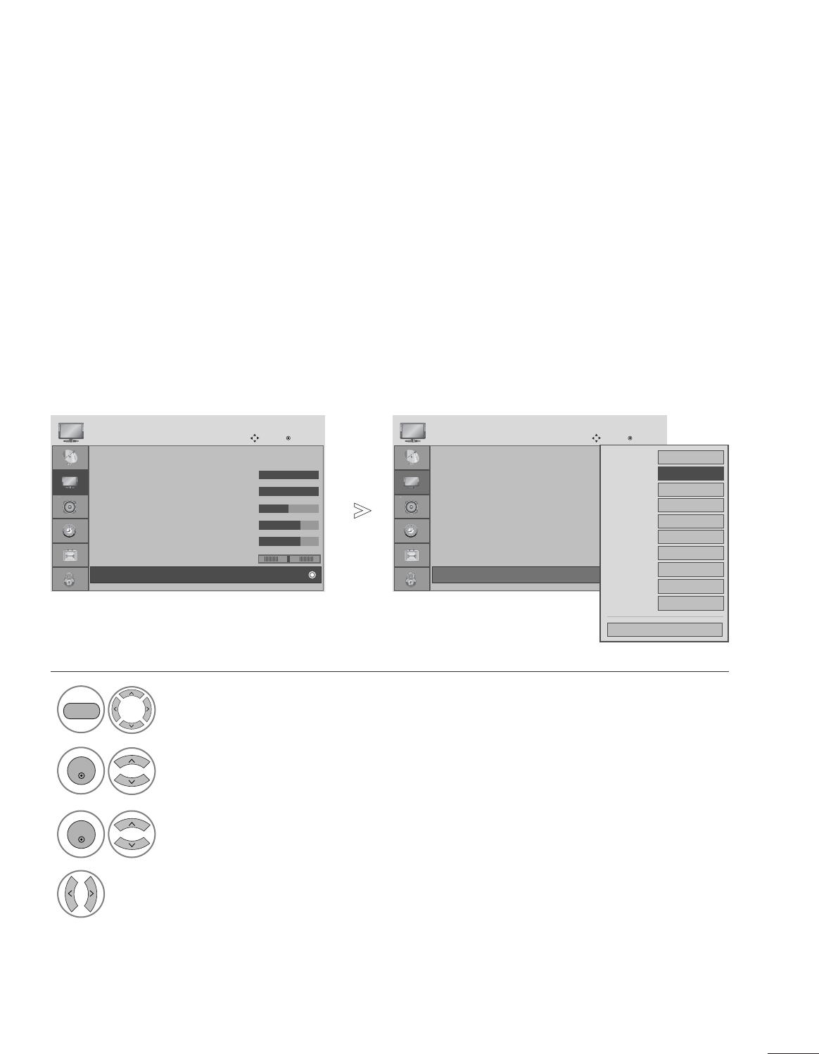
PICTURE CONTROL
This feature lets you choose the way an analog picture with a 4:3 aspect ratio is displayed on your set.
■ RGB-PC input source use 4:3 or 16:9 aspect ratio.
PICTURE SIZE (ASPECT RATIO) CONTROL
Q.Menu
3
F16:9 G
Standard
Vivid
Off
English
Off
Add
Aspect Ratio
Backlight
Picture Mode
Sound Mode
Caption
Multi Audio
Sleep Timer
Del/Add/Fav
CH
Close
Just ScanZoom1Zoom2
Set By Program
4:3 16:9
NOTE
!
GIf a fixed image is displayed on the screen for a long time, the image could become imprinted on the
screen and remain visible.
This phenomenon is common to all manufacturers and is not covered by warranty. Although, after watch-
ing video that did not fill the screen, any after-image from the black bars will normally dissipate after a few
minutes.
• Press the RETURN button to move to the previous menu screen.
1
RATIO
Select the desired picture format.
34
PICTURE CONTROL
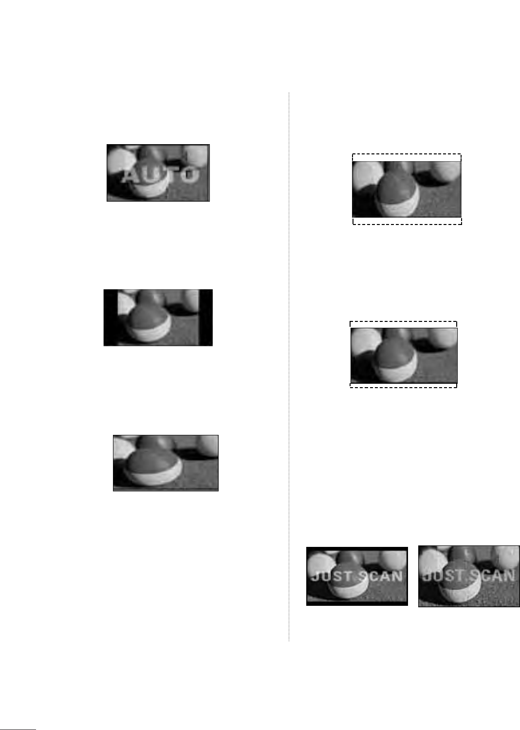
Set by program
Selects the proper picture proportion to match
the source’s image.
4:3
Choose 4:3 when you want to view a picture
with an original 4:3 aspect ratio.
• 16:9
Adjust the picture horizontally, in a linear pro-
portion to fill the entire screen.
Zoom 1
Choose Zoom 1 when you want to view the pic-
ture without any alteration. However, the top and
bottom portions of the picture will be cropped.
Zoom 2
Choose Zoom 2 when you want the picture to
be altered, both vertically extended and
cropped. The picture taking a halfway trade off
between alteration and screen coverage.
Just Scan
Following selection will lead to you view the pic-
ture of best quality without loss of original pic-
ture in high resolution image.
Notes: If there are noise in original picture, you
can see the noise at the edge.
Just Scan operates only in
DTV/CADTV/Component/HDMI-DTV/DVI-DTV
(720p/1080i/1080p) input source.
35
PICTURE CONTROL
• Press the RETURN button to move to the previous menu screen.
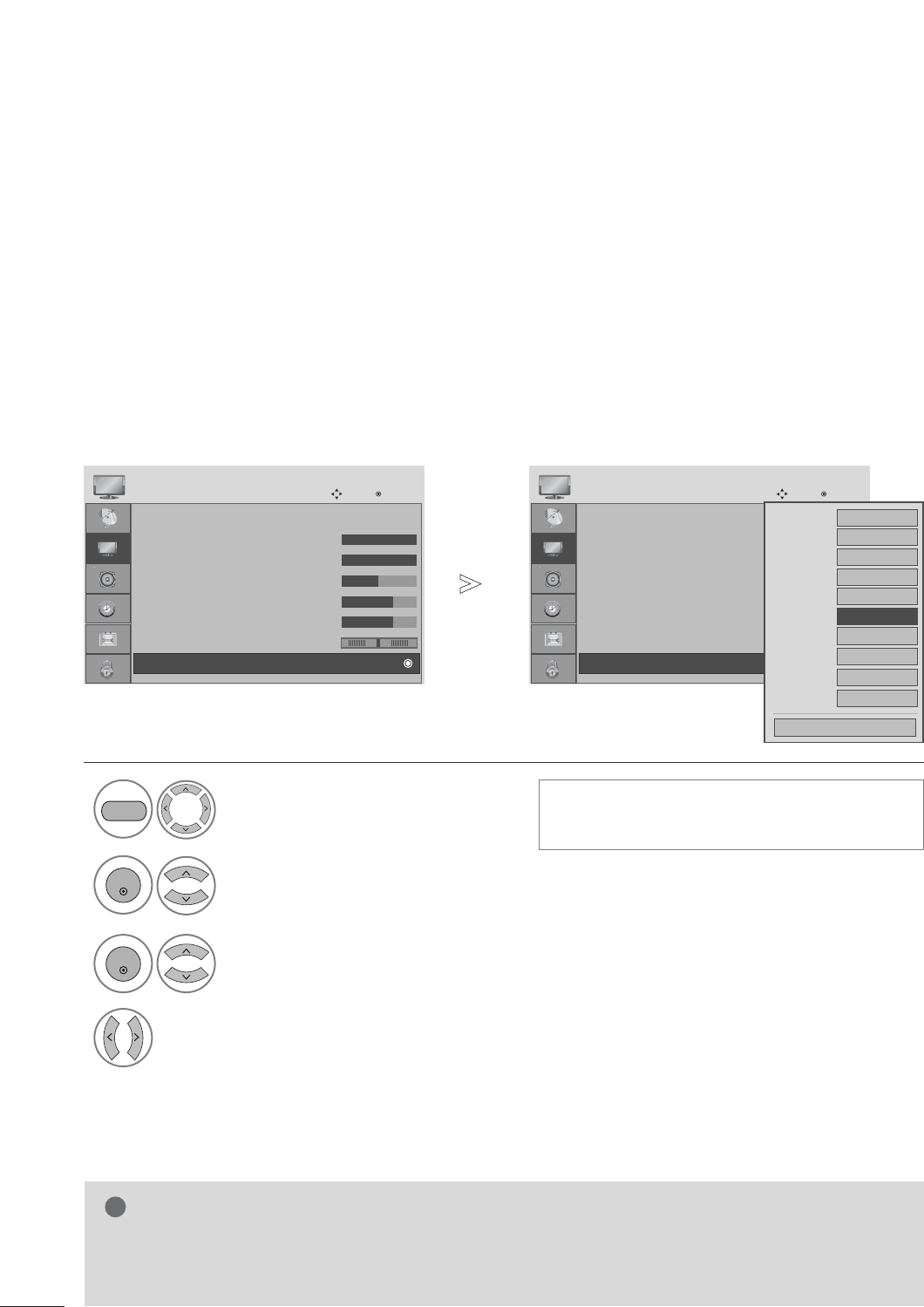
PRESET PICTURE SETTINGS
Picture Mode-Preset
There are factory presets for picture settings available in the user menus. You can use a preset, change each set-
ting manually.
1
PICTURE
Vivid Standard
Game Sport
Cinema
Select Vivid,Standard, Cinema, Sport, or Game.■Vivid,Standard, Cinema, Sport, or
Game Settings are preset for the opti-
mum picture quality at the factory and are
not adjustable.
Q.Menu
3
16:9
Standard
F Vivid G
Off
English
Off
Add
Aspect Ratio
Backlight
Picture Mode
Sound Mode
Caption
Multi Audio
Sleep Timer
Del/Add/Fav
CH
Close
36
PICTURE CONTROL
Select PICTURE.
2Select Auto Bright.
3Select On or Off.
1
MENU
ENTER
ENTER
When ON is selected, this function adjusts the screen brightness automatically, depending on the surrounding
environment, to provide optimal viewing conditions.
When OFF is selected, this function is turned off.
AUTO BRIGHT
Aspect Ratio : 16:9
Auto Bright : Off
Picture Mode : Vivid
• Backlight 100
• Contrast 100
• Brightness 50
• Sharpness 70
• Color 70
PICTURE
Move Enter
E
Auto Bright : Off
Aspect Ratio : 16:9
Auto Bright : Off
Picture Mode : Vivid
• Backlight 100
• Contrast 100
• Brightness 50
• Sharpness 70
• Color 70
PICTURE
Move Enter
E
Auto Bright : Off
Off
On
Off
• Press the MENU button to close the menu window.
• Press the RETURN button to move to the previous menu screen.
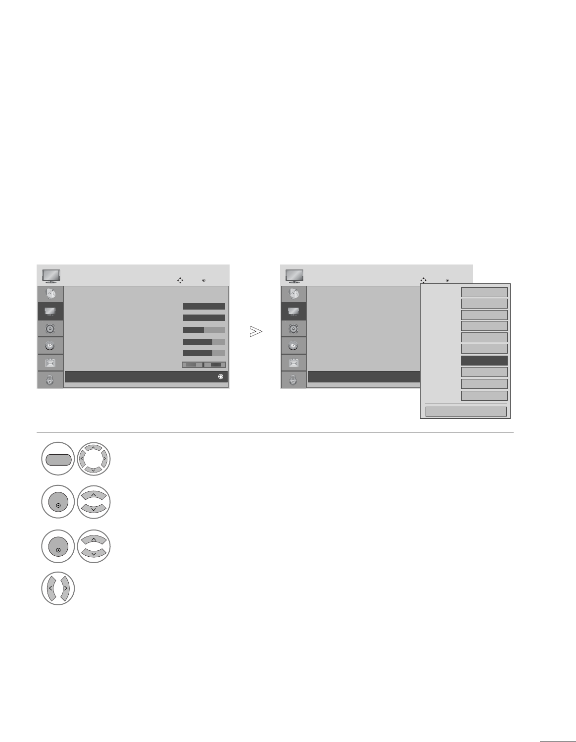
37
PICTURE CONTROL
PRESET PICTURE SETTINGS
Picture Mode-Preset
Select PICTURE.
2Select Picture Mode.
3
Select desired picture value.
1• Picture Mode adjusts the set for the best pic-
ture appearance. Select the preset value in the
Picture Mode menu based on the channel cat-
egory.
MENU
ENTER
ENTER
• Press the MENU button to close the menu window.
• Press the RETURN button to move to the previous menu screen.
Aspect Ratio : 16:9
Auto Bright : Off
Picture Mode : Vivid
• Backlight 100
• Contrast 100
• Brightness 50
• Sharpness 70
• Color 70
PICTURE
Move Enter
E
Picture Mode : Vivid
Aspect Ratio : 16:9
Auto Bright : Off
Picture Mode : Vivid
• Backlight 100
• Contrast 100
• Brightness 50
• Sharpness 70
• Color 70
PICTURE
Move Enter
E
Picture Mode : Vivid
Aspect Ratio : 16:9
Auto Bright : Off
Picture Mode : Vivid
• Backlight 80
• Contrast 100
• Brightness 50
• Sharpness 70
• Color 50
PICTURE
Move Enter
E
Picture Mode : Standrad Vivid
Standard
Cinema
Sport
Game
Standrad
Vivid
Standard
Cinema
Sport
Game
Vivid
<RGB,DVI Mode>
<Other mode>
38
PICTURE CONTROL
Picture Mode : Vivid
• Backlight 100
• Contrast 100
• Brightness 50
• Sharpness 70
• Color 70
• Tint 0
• Advanced Control
PICTURE
Move Enter
E
D
• Advanced Control
Choose one of three automatic color adjustments. Set to warm to enhance warm colors such as red, or set to
cool to see less intense colors with more blue.
Auto Color Tone Control (Warm/Medium/Cool)
Select PICTURE.
2Select Advanced Control.
3Select Color Temperature.
4Select either Cool, Medium or Warm.
1
Picture Mode : Vivid
• Backlight 100
• Contrast 100
• Brightness 50
• Sharpness 70
• Color 70
• Tint 0
• Advanced Control
PICTURE
Move Enter
E
D
• Advanced Control
Color Temperature
F
Cool
G
Fresh Contrast
High
Fresh Color
High
Noise Reduction
Medium
Gamma Medium
Film Mode Off
Red Contrast 0
Green Contrast
0
Blue Contrast 0
Black Level Low
Close
MENU
ENTER
ENTER
• Press the MENU button to close the menu window.
• Press the RETURN button to move to the previous menu screen.
RG
39
PICTURE CONTROL
Choose one of two automatic color adjustments.
Auto Color Tone Control (6500K/9300K/sRGB)(RGB,DVI mode only)
Select PICTURE.
2Select Advanced Control.
3Select Color Temperature.
4Select either 6500K, 9300K, sRGB.
1
Picture Mode : Standard
• Backlight 80
• Contrast 100
• Brightness 50
• Sharpness 70
• Color 50
• Tint 0
• Advanced Control
PICTURE
Move Enter
E
D
• Advanced Control
MENU
ENTER
ENTER
• Press the MENU button to close the menu window.
• Press the RETURN button to move to the previous menu screen.
RG
Picture Mode : Standard
• Backlight 80
• Contrast 100
• Brightness 50
• Sharpness 70
• Color 50
• Tint 0
• Advanced Control
PICTURE
Move Enter
E
D
• Advanced Control
RG
Color Temperature
F
6500K
G
Fresh Contrast
Off
Fresh Color
Off
Noise Reduction
Off
Gamma Medium
Film Mode Off
Red Contrast 0
Green Contrast
0
Blue Contrast 0
Black Level Auto
Close

40
MANUAL PICTURE ADJUSTMENT
Picture Mode-User option
NOTE
!
G You cannot adjust color, sharpness and tint in the RGB, DVI mode.
Select PICTURE.
2Select Picture Mode.
4
Select Backlight, Contrast, Brightness, Sharpness, Color or Tint.
5
Make appropriate adjustments.
1
3
Select desired picture value.
MENU
ENTER
ENTER
ENTER
ENTER
• Press the MENU button to close the menu window.
• Press the RETURN button to move to the previous menu screen.
PICTURE CONTROL
Aspect Ratio : 16:9
Auto Bright : Off
Picture Mode : Vivid
• Backlight 100
• Contrast 100
• Brightness 50
• Sharpness 70
• Color 70
PICTURE
Move Enter
E
Picture Mode : Vivid(User)
Aspect Ratio : 16:9
Auto Bright : Off
Picture Mode : Vivid
• Backlight 100
• Contrast 100
• Brightness 50
• Sharpness 70
• Color 70
PICTURE
Move Enter
E
Picture Mode : Vivid(User)
Aspect Ratio : 16:9
Auto Bright : Off
Picture Mode : Vivid
• Backlight 80
• Contrast 100
• Brightness 50
• Sharpness 70
• Color 50
PICTURE
Move Enter
E
RG
Picture Mode : Standard (User) Vivid
Standard
Cinema
Sport
Game
Standard(User)
Vivid
Standard
Cinema
Sport
Game
Vivid(User)
<RGB,DVI Mode>
<Other mode>
41
PICTURE CONTROL
Picture Mode : Vivid
• Backlight 100
• Contrast 100
• Brightness 50
• Sharpness 70
• Color 70
• Tint 0
• Advanced Control
PICTURE
Move Enter
E
D
• Advanced Control
Fresh Contrast
Optimizes the contrast automatically according to the brightness of the reflection.
Fresh Color
Adjusts the color of the reflection automatically to reproduce natural colors as close as possible.
Noise Reduction
Removes interference up to the point where it does not damage the original picture.
Gamma
High gamma values display whitish images and low gamma values display high contrast images.
PICTURE IMPROVEMENT TECHNOLOGY
Select PICTURE.
2Select Advanced Control.
3Select Fresh Contrast,Fresh Color, Noise Reduction or Gamma.
4Select your desired Source.
1
Picture Mode : Vivid
• Backlight 100
• Contrast 100
• Brightness 50
• Sharpness 70
• Color 70
• Tint 0
• Advanced Control
PICTURE
Move Enter
E
D
• Advanced Control
MENU
ENTER
ENTER
Color Temperature
Cool
Fresh Contrast
F
High
G
Fresh Color
High
Noise Reduction
Medium
Gamma Medium
Film Mode Off
Black Level Auto
Close
• Press the MENU button to close the menu window.
• Press the RETURN button to move to the previous menu screen.
RG
Red Contrast 0
Green Contrast
0
Blue Contrast 0
42
ADVANCED - BLACK (DARKNESS) LEVEL
When you view a film, this function adjusts the set to the best picture quality.
This function works in the following mode: ATV, AV(NTSC-M), Component, HDMI
Select PICTURE.
2Select Advanced Control.
3Select Black Level.
4Select Low or High.
1
Picture Mode : Vivid
• Backlight 100
• Contrast 100
• Brightness 50
• Sharpness 70
• Color 70
• Tint 0
• Advanced Control
PICTURE
Move Enter
E
D
• Advanced Control
• Low: The reflection of the screen gets darker.
• High: The reflection of the screen gets brighter.
MENU
ENTER
ENTER
• Press the MENU button to close the menu window.
• Press the RETURN button to move to the previous menu screen.
RG
Picture Mode : Vivid
• Backlight 100
• Contrast 100
• Brightness 50
• Sharpness 70
• Color 70
• Tint 0
• Advanced Control
PICTURE
Move Enter
E
D
• Advanced Control
RG
NOTE
!
G If input is not ATV, AV(NTSC-M), HDMI or component, this function set to auto.
G In case of auto, user can’t adjust it directly.
G Auto: Realizing the black level of the screen and set it to High or Low automatically.
Color Temperature
Cool
Fresh Contrast
High
Fresh Color
High
Noise Reduction
Medium
Gamma Medium
Film Mode Off
Black Level
F
High
G
Close
Red Contrast 0
Green Contrast
0
Blue Contrast 0
PICTURE CONTROL
43
PICTURE CONTROL
Select PICTURE.
2Select Advanced Control.
3Select Film Mode.
4Select On or Off.
1
Picture Mode : Vivid
• Backlight 100
• Contrast 100
• Brightness 50
• Sharpness 70
• Color 70
• Tint 0
• Advanced Control
PICTURE
Move Enter
E
D
• Advanced Control
ADVANCED - FILM MODE
To set the product up for the best picture quality for viewing films.
This feature operates only in TV, AV and Component 480i/1080i , HDMI 1080i mode.
MENU
ENTER
ENTER
• Press the MENU button to close the menu window.
• Press the RETURN button to move to the previous menu screen.
RG
Picture Mode : Vivid
• Backlight 100
• Contrast 100
• Brightness 50
• Sharpness 70
• Color 70
• Tint 0
• Advanced Control
PICTURE
Move Enter
E
D
• Advanced Control
RG
Color Temperature
Cool
Fresh Contrast
High
Fresh Colour
High
Noise Reduction
Medium
Gamma Medium
Film Mode
F
Off
G
Black Level Auto
Close
Red Contrast 0
Green Contrast
0
Blue Contrast 0
44
PICTURE CONTROL
PICTURE RESET
Settings of the selected picture modes return to the default factory settings.
Select PICTURE.
2Select Picture Reset.
3
Initialize the adjusted value.
1
• Backlight 100
• Contrast 100
• Brightness 50
• Sharpness 70
• Color 70
• Tint 0
• Advanced Control
PICTURE
Move Enter
D
• Reset
MENU
ENTER
ENTER
RG
• Backlight 100
• Contrast 100
• Brightness 50
• Sharpness 70
• Color 70
• Tint 0
• Advanced Control
PICTURE
Move Enter
D
• Reset
RG
Resetting video configuration...
i
• Press the MENU button to close the menu window.
• Press the RETURN button to move to the previous menu screen.
45
PICTURE CONTROL
To view a normal picture, set the resolution to match what the PC is using.
This function works in the following resolution in RGB[PC] mode.
Selecting Resolution
1Select PICTURE.
<Vertical resolution : 768>
<Vertical resolution : 1050>
2Select SCREEN(RGB-PC).
3Select Resolution.
4Select the desired resolution.
MENU
ENTER
ENTER
• Press the MENU button to close the menu window.
• Press the RETURN button to move to the previous menu screen.
1024 x 768
128 0 x 768
136 0 x 768
136 6 x 76 8
Auto Config.
SCREEN
Move
Resolution
G
Position
Size
Phase
Reset
Prev.
MENU
1400 x 1050
1680 x 1050
Auto Config.
SCREEN
Move
Resolution
G
Position
Size
Phase
Reset
Prev.
MENU
• Contrast : 100
• Brightness : 50
• Sharpness : 70
• Colour : 50
• Tint : 0
• Advanced Control
• Reset
PICTURE
Move Enter
D
Screen(RGB-PC)
RG
SCREEN SETUP FOR PC MODE
62
OPTION SETTING
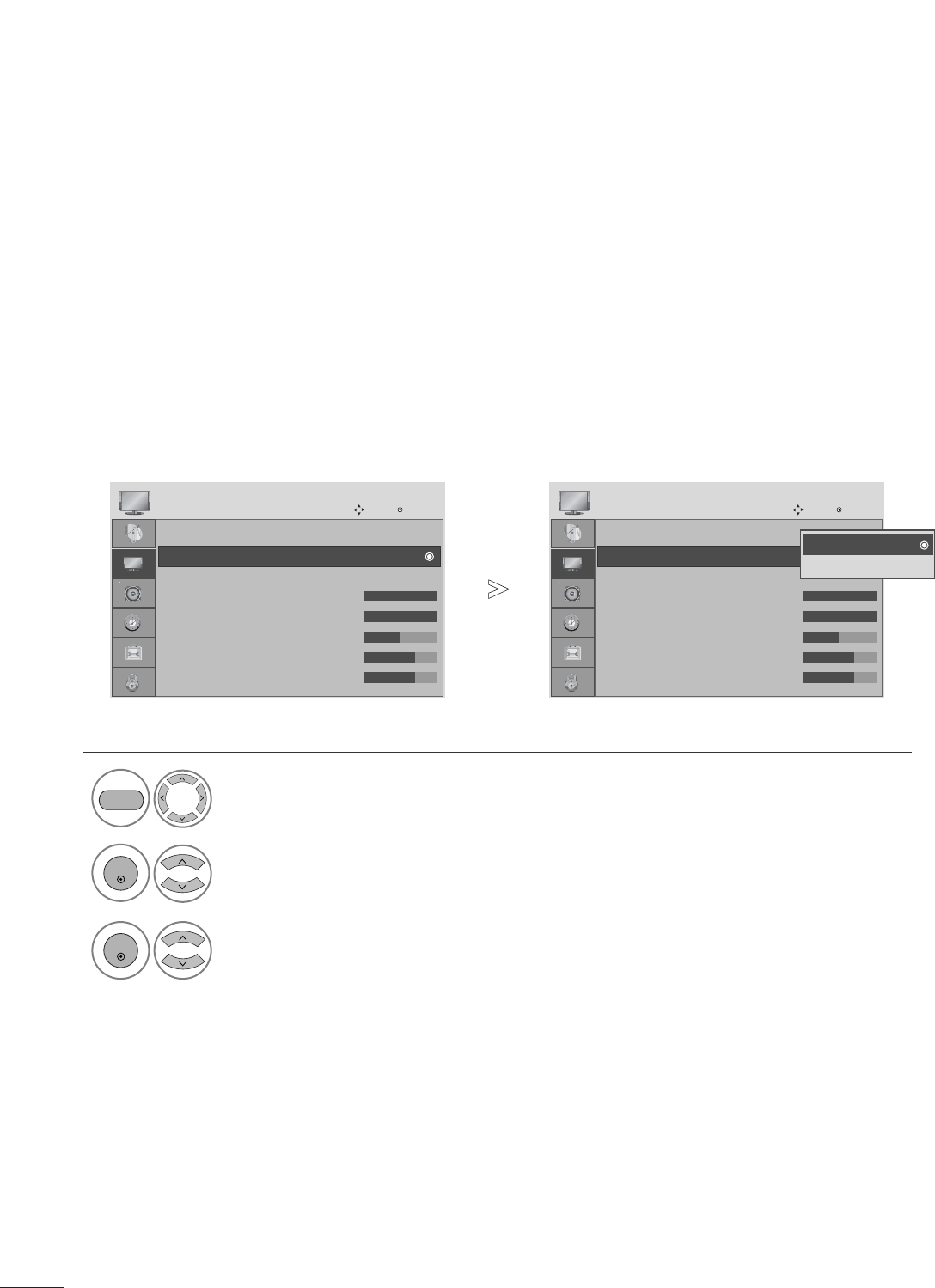
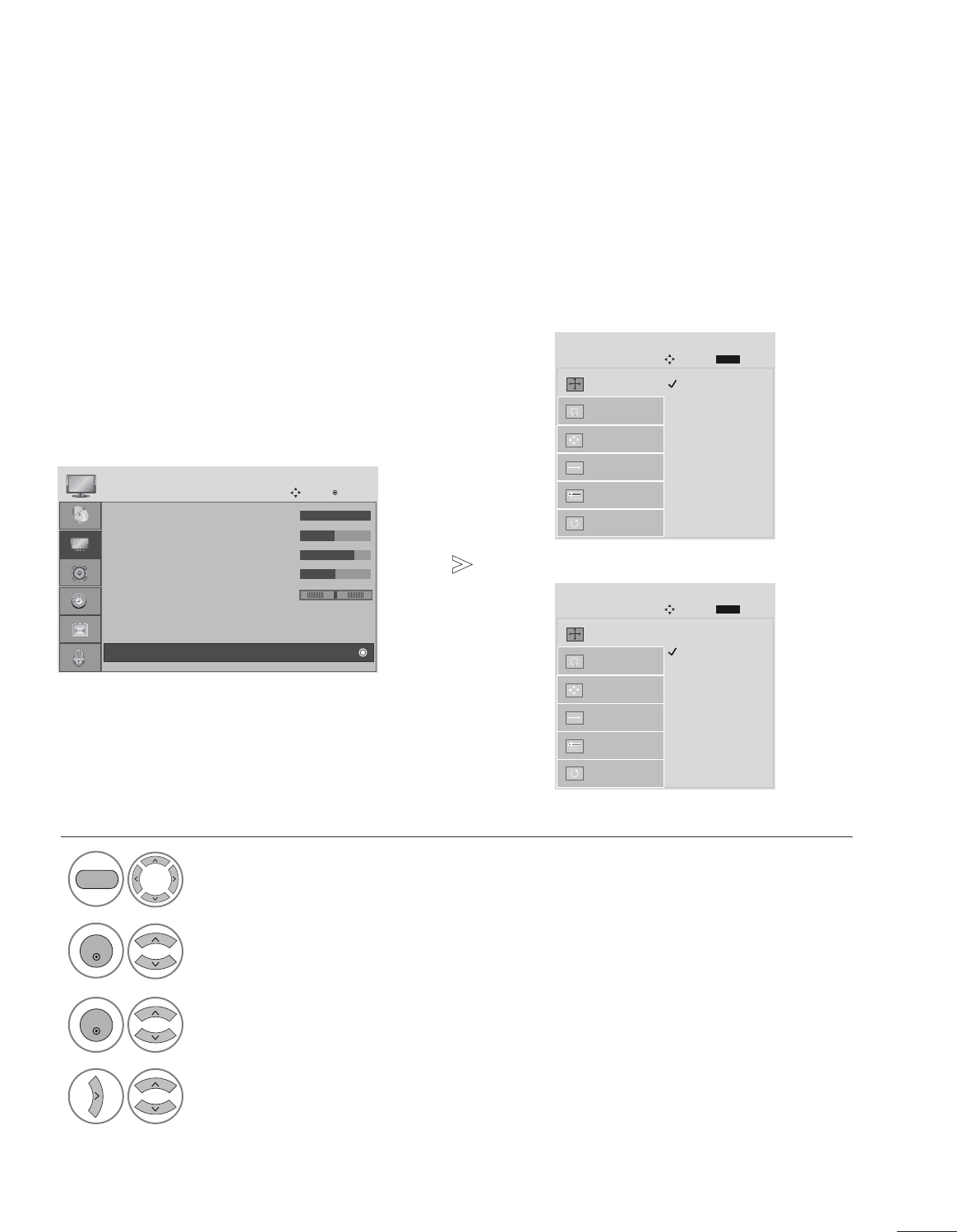
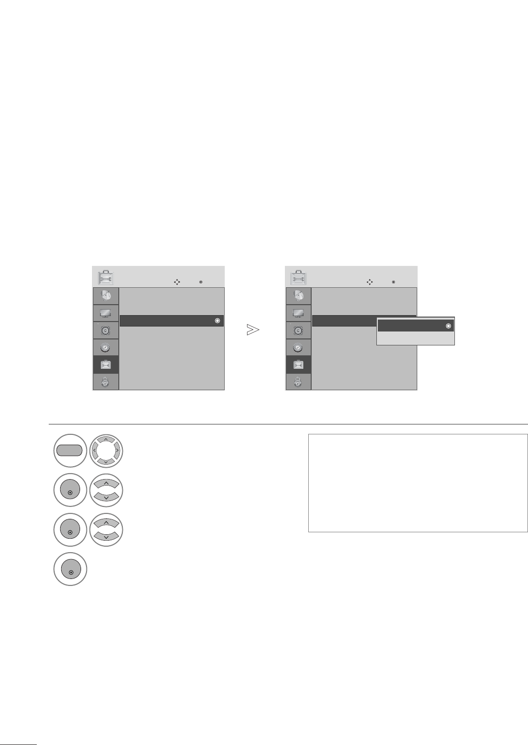
The menus can be shown on the screen in the selected language.
ON-SCREEN MENUS LANGUAGE SELECTION
Select OPTION.
2Select Language.
3Select Menu.
4Select your desired language.
From this point on, the on-screen menus will be shown in the selected language.
1
MENU
ENTER
ENTER
• Press the MENU button to close the menu window.
• Press the RETURN button to move to the previous menu screen.
Language : English
Input Label
Key Lock : Off
Caption : Off
Set ID : 1
Power Indicator : On
DDC-CI : On
RTC : On
OPTION
Move Enter
E
Language : English
Language : English
Input Label
Key Lock : Off
Caption : Off
Set ID : 1
Power Indicator : On
DDC-CI : On
RTC : On
OPTION
Move Enter
E
Language : English
Menu FEnglish G
Audio English
Close
63
OPTION SETTING
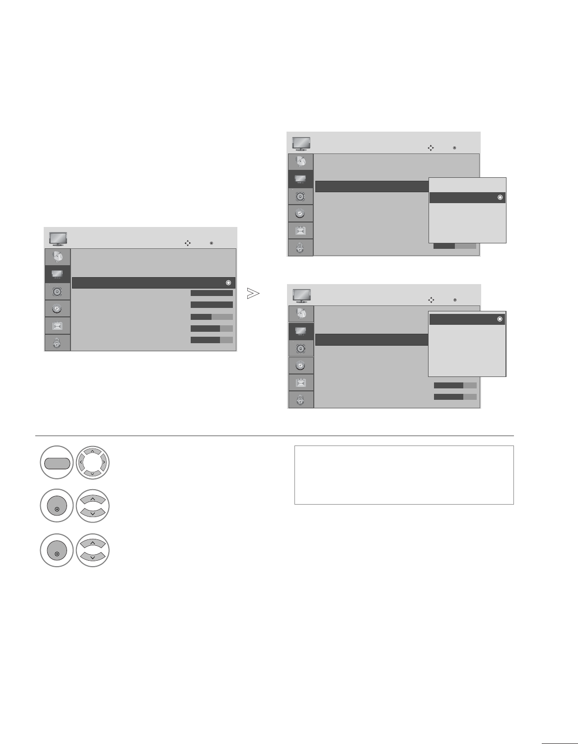
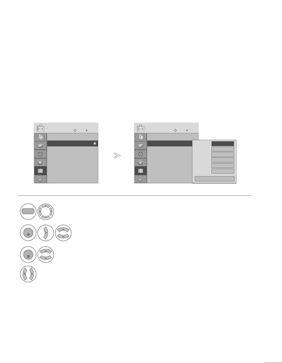
Selects a label for each input source.
INPUT LABEL
Select OPTION.
2Select Input Label.
3
Select the source.
4
Select the label.
1
MENU
ENTER
ENTER
• Press the MENU button to close the menu window.
• Press the RETURN button to move to the previous menu screen.
Language : English
Input Label
Key Lock : Off
Caption : Off
Set ID : 1
Power Indicator : On
DDC-CI : On
RTC : On
OPTION
Move Enter
E
Input Label
Language : English
Input Label
Key Lock : Off
Caption : Off
Set ID : 1
Power Indicator : On
DDC-CI : On
RTC : On
OPTION
Move Enter
E
Input Label
RGB-PC
HDMI 1
HDMI 2
DVI
AV
Component
Close
64
OPTION SETTING
The set can be configured so that the remote control is required to control it. This feature can be used to
prevent unauthorized viewing.
KEY LOCK
Select OPTION.
2Select Key Lock.
3Select On or Off.
4Save.
1• In Key Lock ’On’, if the set is turned off, press
the r/ I, INPUT, CH D E button on the TV or
POWER, INPUT, CH + - or NUMBER buttons on
the remote control.
• With the Key Lock On, the display ‘ Key Lock’
appears on the screen if any button on the front
panel is pressed while viewing the TV.
ENTER
ENTER
• Press the MENU button to close the menu window.
• Press the RETURN button to move to the previous menu screen.
ENTER
MENU
Language : English
Input Label
Key Lock : Off
Caption : Off
Set ID : 1
Power Indicator : On
DDC-CI : On
RTC : On
OPTION
Move Enter
E
Key Lock : Off
Language : English
Input Label
Key Lock : Off
Caption : Off
Set ID : 1
Power Indicator : On
DDC-CI : On
RTC : On
OPTION
Move Enter
E
Key Lock : OffOff
On
Off
70
OPTION SETTING
• Press the MENU button to close the menu window.
• Press the RETURN button to move to the previous menu screen.
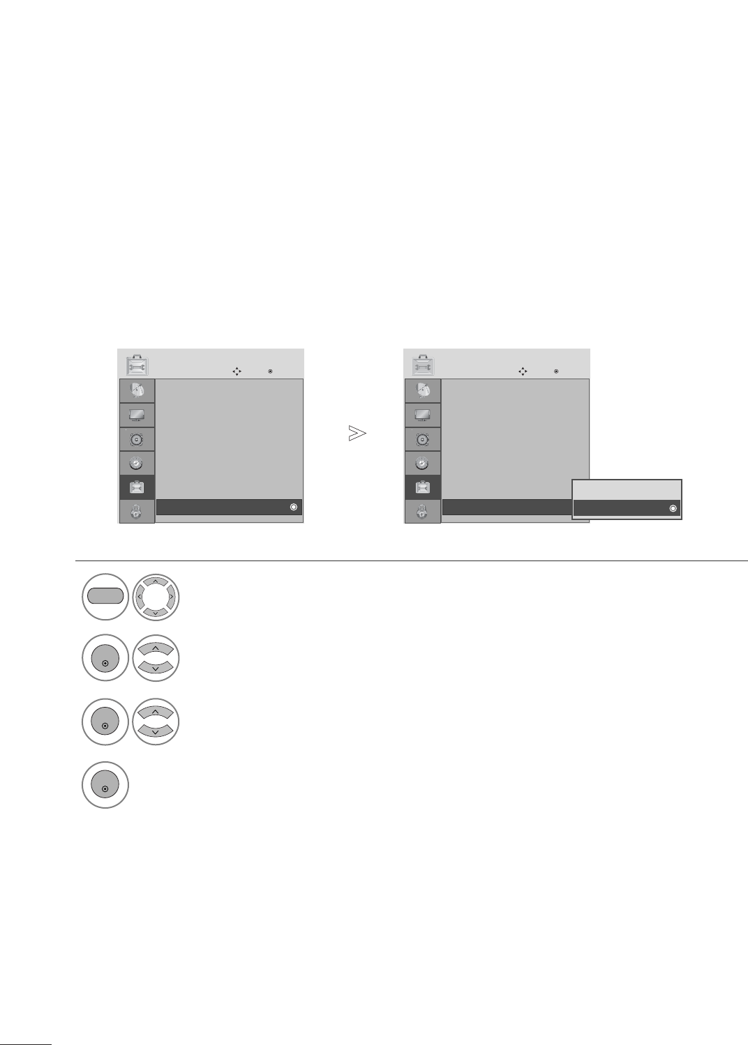
If you set ON, you enable the response time control function.
If you set OFF, you disenable the response time control function.
RTC(Only M2762D)
1Select OPTION.
2Select RTC.
MENU
ENTER
Select On or Off.
3
ENTER
4
ENTER
Language : English
Input Label
Key Lock : Off
Caption : Off
Set ID : 1
Power Indicator : On
DDC-CI : On
RTC : On
OPTION
Move Enter
RTC : On
E
Language : English
Input Label
Key Lock : Off
Caption : Off
Set ID : 1
Power Indicator : On
DDC-CI : On
RTC : On
OPTION
Move Enter
RTC : On
E
Off
On
On
71
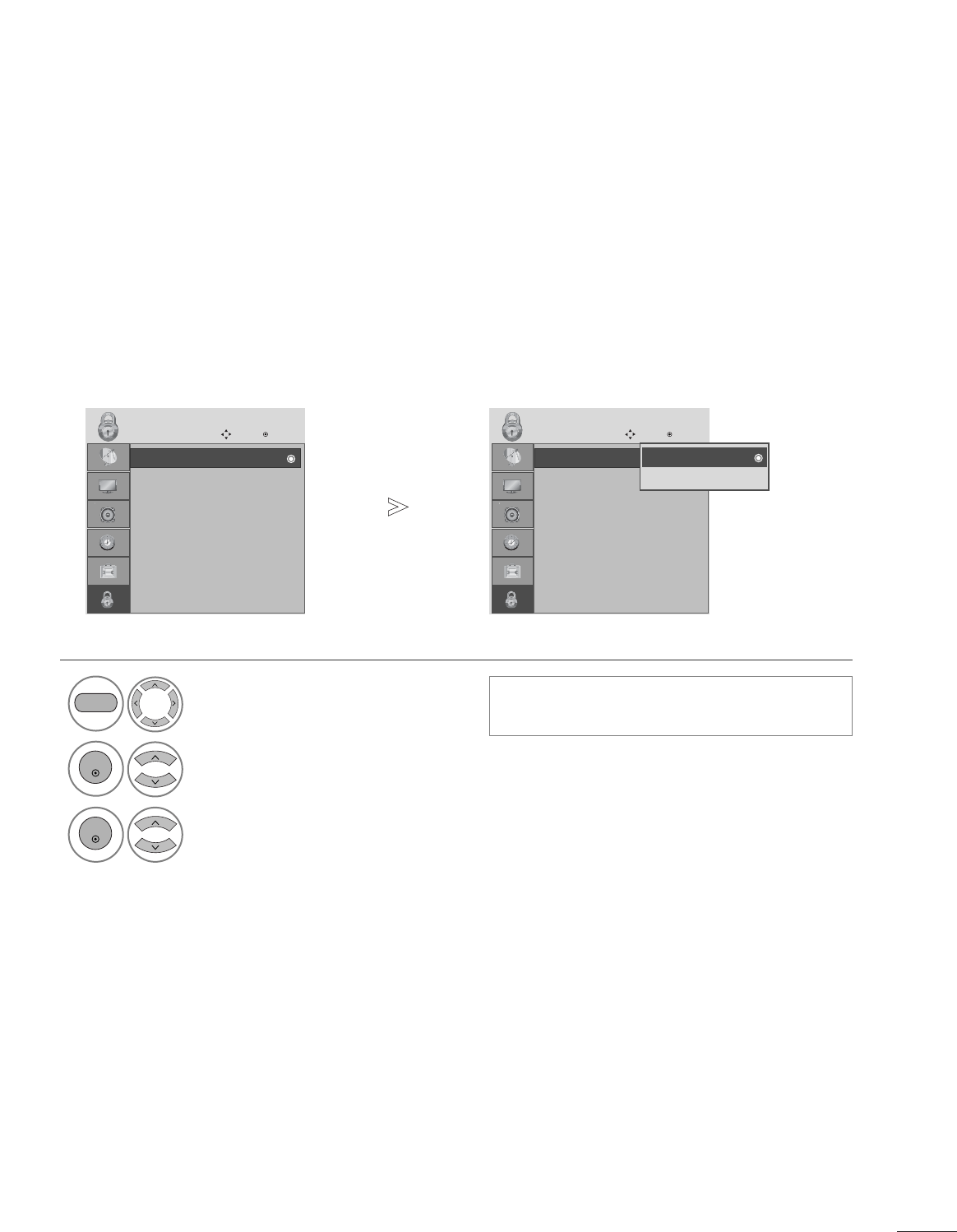
PARENTAL CONTROL / RATINGS
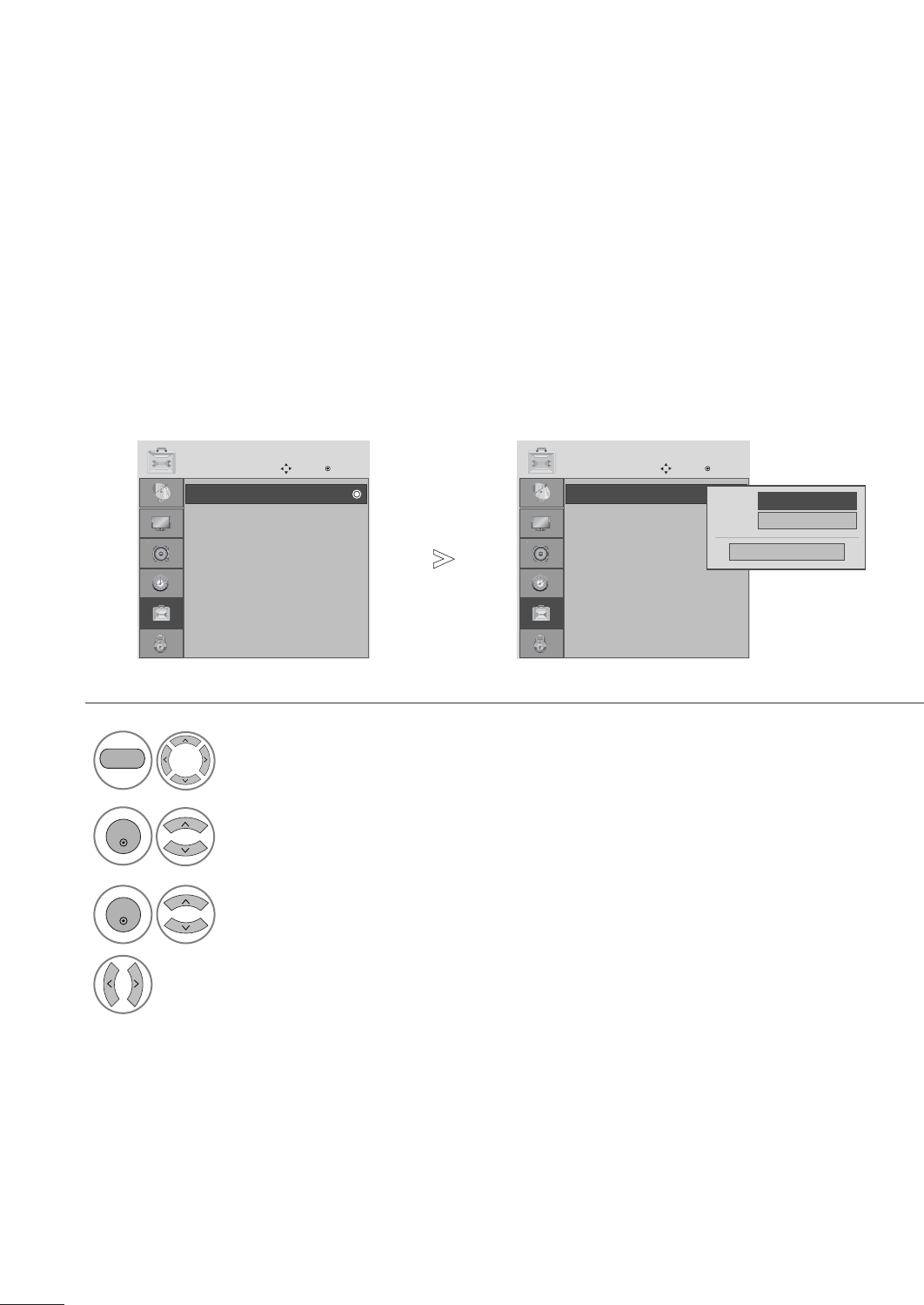
LOCK SYSTEM
Enter the password, press ‘0’, ‘0’, ‘0’, ‘0’ on the remote control handset.
Select LOCK.
2Select Lock System.
3Select On or Off.
1
• When you select On, the Lock System is enable.
MENU
ENTER
ENTER
• Press the MENU button to close the menu window.
• Press the RETURN button to move to the previous menu screen.
Lock System : Off
Set Password
Block Channel
Movie Rating
TV Rating-Children
TV Rating-General
Downloadable Rating
Input Block
LOCK
Move Enter
Lock System : Off Lock System : Off
Set Password
Block Channel
Movie Rating
TV Rating-Children
TV Rating-General
Downloadable Rating
Input Block
LOCK
Move Enter
Lock System : OffOff
On
Off
72
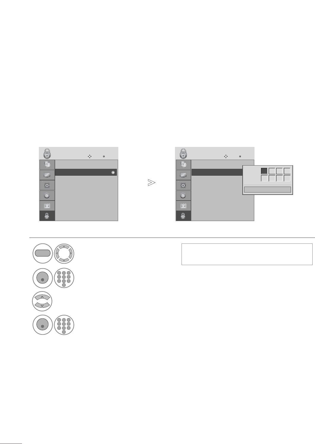
PARENTAL CONTROL / RATINGS
SET PASSWORD
Select LOCK.
2Select Set password.
Input the password.
3Choose any 4 digits for your new password.
As soon as the 4 digits are entered, re-enter the
same 4 digits on the Confirm.
1• If you forget your password, press ‘7’, ‘7’, ‘7’, ‘7’
on the remote control handset.
MENU
ENTER
ENTER
2
123
456
78
0
9
123
456
78
0
9
• Press the MENU button to close the menu window.
• Press the RETURN button to move to the previous menu screen.
Lock System : Off
Set Password
Block Channel
Movie Rating
TV Rating-Children
TV Rating-General
Downloadable Rating
Input Block
LOCK
Move Enter
Set Password
Lock System : Off
Set Password
Block Channel
Movie Rating
TV Rating-Children
TV Rating-General
Downloadable Rating
Input Block
LOCK
Move Enter
Set Password
Close
New ** * *
Confirm * * * *
73
PARENTAL CONTROL / RATINGS
BLOCK CHANNEL
Blocks any programs that you do not want to watch or that you do not want your children to watch.
This function is available in Lock System “On”.
Select LOCK.
2Select Block Channel.
1
3
Q.MENU
Select a channel to block or unblock it.
4
Block or unblock a channel.
ENTER
Q.MENU
• Press the MENU button to close the menu window.
• Press the RETURN button to move to the previous menu screen.
Lock System : Off
Set Password
Block Channel
Movie Rating
TV Rating-Children
TV Rating-General
Downloadable Rating
Input Block
LOCK
Move Enter
Block Channel
Move Page
CH
Move Previous
RETURN Block/Unblock
Q.MENU
MENU
79
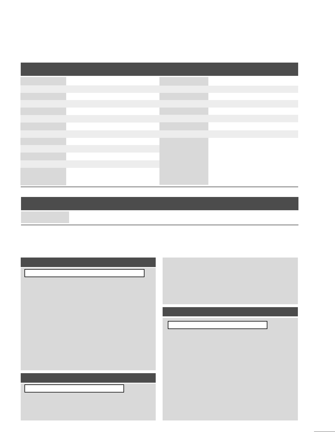
No picture & No sound
No color, poor color,
or poor picture
Poor reception on
some channels
Lines or streaks
in pictures
Horizontal/vertical bars
or picture shaking
Picture appears slowly
after switching on
ACheck whether the product is turned on.
ATry another channel. The problem may be with the broadcast.
AIs the power cord inserted into wall power outlet?
ACheck your antenna direction and/or location.
ATest the wall power outlet, plug another product’s power cord into the outlet
where the product’s power cord was plugged in.
AThis is normal, the image is muted during the product startup process. If the
picture does not appear after a minute, unplug the TV for 30 seconds and try it
again. If the picture still doesn’t appear, contact an authorized service center in
your area.
AAdjust Color in the menu.
AKeep a sufficient distance between this product and other electronics.
ATry another channel. The problem may be with the broadcast.
AAre the video cables installed properly?
ACheck for local interference such as an electrical appliance or power tool.
AStation or cable product experiencing problems, tune to another station.
AStation signal is weak, reorient antenna.
ACheck for sources of possible interference.
ACheck antenna (Change the direction of the antenna).
TROUBLESHOOTING
The operation does not work normally.
The remote control
doesn’t work
TV turns off suddenly
A
Check to see if there is any object between the product and the remote control caus-
ing obstruction. Ensure you are pointing the remote control directly at the set.
A
Ensure that the batteries are installed with correct polarity (+ to +, - to -).
A
Ensure that the correct remote operating mode is set: TV, VCR, etc.
A
Install new batteries.
A
Is the sleep timer set?
A
Check the power control settings. Power interrupted.
A
No broadcast on station tuned with Auto sleep activated.
The video function does not work.
APPENDIX
80
APPENDIX
No Audio.
APress the VOL + or -button.
ASound muted? Press MUTE button.
ATry another channel. The problem may be with the broadcast.
AAre the audio cables installed properly?
AAdjust Balance in menu option.
AA change in ambient humidity or temperature may result in an unusual noise
when the product is turned on or off and does not indicate a problem with
the product.
Picture OK but no sound
Unusual sound from
inside
the product
No output from one
of the speakers
No Video.
A
Adjust brightness and contrast again.
A
If the product is in power saving mode, move the mouse or press any key.
A
The signal from the PC (Video card) is out of the vertical or horizontal
frequency range of the product.
Adjust the video settings on the PC to match one of accepted resolution/fre-
quency settings listed in this manual.
A
The signal cable between PC and product is not connected. Check the signal
cable.
A
Press the ‘INPUT’ button in the remote control to check the input source set-
ting.
Power is on, power indic-
tor is blue but the screen
appears extremely dark.
Does the ‘Out of range’
message appear?
Does the power indica-
tor look amber?
When using PC input (RGB or DVI)
Does the ‘Check signal
cable’ message appear?
81
APPENDIX
The screen image looks abnormal.
AAdjust the Position menu in OSD.
ASee if the video card resolution and frequency are supported by the product.
If the frequency is out of range, set to the recommended resolution using
the display settings on the PC.
AAdjust the Clock menu in OSD.
AAdjust the Phase menu in OSD.
Is the picture offset?
Horizontal noise appears
or the characters look
blurred.
Do thin lines appear on
the background screen?
Screen color is abnormal.
ASet screen color resolution to 24 bits (true Color) or more using the display
settings on the PC.
ACheck the connection status of the signal cable.
ASeveral pixels (red, green, white or black color) may appear on the screen,
which can be attributable to the unique characteristics of the LCD panel.
It is not a malfunction of the LCD.
Screen has poor color res-
olution (16_colors).
Do back spots appear on
the screen?
Screen color is unstable
or mono color.
After-image appears on the screen.
AThe pixels may have been damaged if there was fixed image on the display for
a long time. Use a screen saver.
After-image appears when
the product is turned off.
‘Unknown Product’ message appears when the product is connected.
AInstall the product driver, which is provided with the product, or download it
from the web site.
(http://www.lge.com)
AThe Video card in the PC is not properly communicating with the monitor. Try
installing the latest drivers for the video card.
Did you install the driver?
RGB PC Mode

82
MAINTENANCE
Careful and regular cleaning can extend the amount of time you can enjoy your new set.
Caution: Be sure to turn the power off and unplug the power cord before you begin any cleaning.
Cleaning the Screen
To keep the dust off your screen for a while, wet a soft cloth in a mixture of lukewarm water and a little fab-
ric softener or dishwashing detergent. Wring the cloth until it’s almost dry, and then use it to wipe the
screen.
Make sure the excess water is off the screen, and then let it air-dry before you turn on your set.
Cleaning the Cabinet
ATo remove dirt or dust, wipe the cabinet with a soft, dry, lint-free cloth.
APlease be sure not to use a wet cloth.
Extended Absence
GIf you expect to leave your set dormant for a long time (such as a vacation), it’s a good idea to unplug
the power cord to protect against possible damage from lightning or power surges.
CAUTION
2
1
APPENDIX
83
APPENDIX
PRODUCT SPECIFICATIONS
■The specifications shown above may be changed without prior notice for quality improvement.
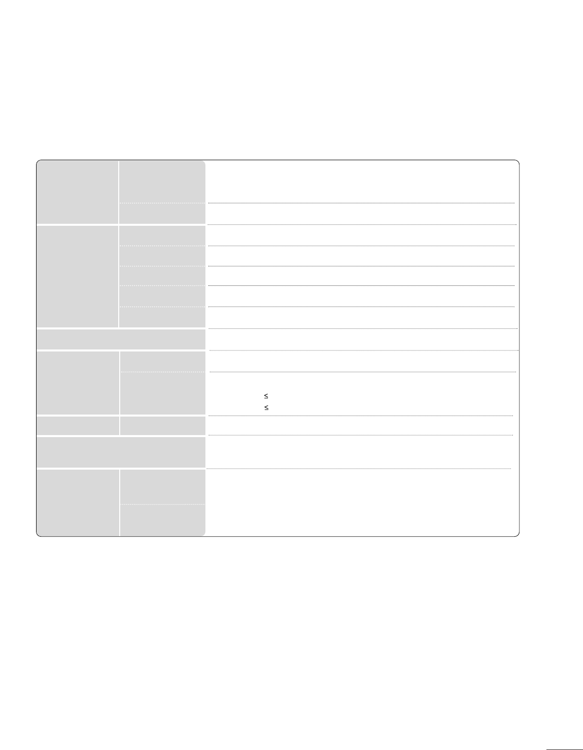
Power AC 100-240V ~50/60 Hz 0.9A
On Mode : 53W (typ.)
Sleep Mode 1W
Off Mode 0.5W
LCD Panel Screen Type
Pixel Pitch
21.53 inches Wide (546.86 mm) TFT (Thin Film Transistor)
LCD (Liquid Crystal Display) Panel
Visible diagonal size : 546.86 mm
0.248 (H) x 0.248(V) mm
Max. Resolution
Recommended Resolution
Horizontal Frequency
Vertical Frequency
Synchronization Type
Video Signal 1920 X 1080 @ 60 Hz
1920 X 1080 @ 60 Hz
30 - 83 kHz
56 - 75 Hz
Separate Sync, Digital
Input Connector TV, D-Sub Analog, PC Audio In, component, DVI-D, HDMI*2, CVBS, S-VIDEO
Rated Voltage
Power Consumption
Tilt Tilt Range -5 ~15 °
Dimensions (Width x Height x Depth)
Weight
517.2 x 399.8 x 221.6 mm (20.36 x 15.74 x 8.72 inches)
4.7 kg / 10.4 lbs
10 ~35°C
20 ~80%
-10 ~60°C
5 ~90%
Operating Temperature
Operating Humidity
Storage Temperature
Storage Humidity
Environmental
conditions
<M2262D>

86
PROGRAMMING CODE
APPENDIX
PROGRAMMING THE REMOTE CONTROL
Programming a code into a remote mode
To find out whether your remote control can operate the component without programming, turn on the
component such as a VCR and press the corresponding mode button (such as a DVD or VCR) on the
remote control. While pointing at the component, test the POWER and PR + / - buttons to see if the
component responds properly. If not, the remote requires programming to operate the device.
Turn on the component to be programmed, then press the corresponding mode button (such as a DVD or
VCR) on the remote control. The remote control button of desired device is lighted.
Press the MENU and MUTE buttons simultaneously. Now the remote control is ready to be programmed
with the new code.
Enter a code number using the number buttons on the remote control. Programming code numbers for the
corresponding component can be found on the following pages. If the code is correct, the device will turn
off.
Press the MENU button to store the code.
Test the remote control functions to see if the component responds properly. If not, repeat from step 2.
The remote is a multi-brand or universal remote. It can be programmed to operate most remote-con-
trollable devices of other manufacturers.
Note that the remote may not control all models of other brands.
1
2
3
4
5
6
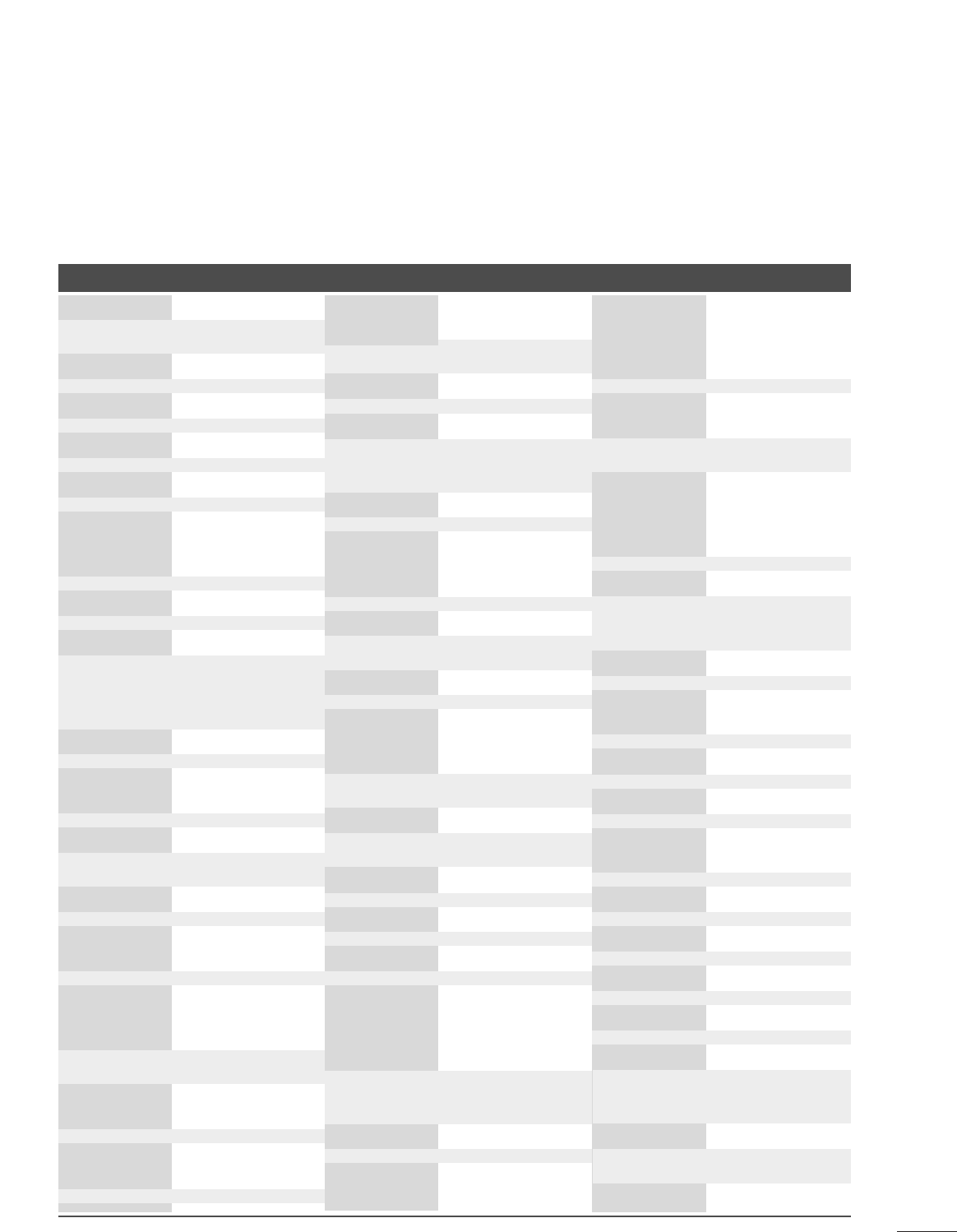
Brand Codes Brand Codes Brand Codes
DVD
APEX DIGITAL 022
DENON 020 014
GE 005 006
HARMAN KARDON 027
JVC 012
LG 001 010 016 025
MAGNAVOX 013
MARANTZ 024
MITSUBISHI 002
NAD 023
ONKYO 008 017
PANASONIC 003 009
PHILIPS 013
PIONEER 004 026
PROCEED 021
PROSCAN 005 006
RCA 005 006
SAMSUNG 011 015
SONY 007
THOMPSON 005 006
TOSHIBA 019 008
YAMAHA 009 018
ZENITH 010 016 025
87
APPENDIX
Brand Codes Brand Codes Brand Codes
AIWA 034
AKAI 016 043 046 124
125 146
AMPRO 072
ANAM 031 033 103
AUDIO DYNAMICS
012 023 039 043
BROKSONIC 035 037 129
CANON 028 031 033
CAPEHART 108
CRAIG 003 040 135
CURTIS MATHES 031 033 041
DAEWOO 005 007 010 064
0 6 5 10 8 110 111
112 116 117 119
DAYTRON 108
DBX 012 023 039 043
DYNATECH 034 053
ELECTROHOME 059
EMERSON 006 017 025 027
029 031 034 035
036 037 046 101
129 131 138 153
FISHER 003 008 009 010
FUNAI 034
GE 031 033 063 072
107 109 144 147
GO VIDEO 132 136
HARMAN KARDON 012 045
HITACHI 004 018 026 034
043 063 137 150
INSTANTREPLAY 031 033
JCL 031 033
JCPENNY 012 013 015 033
040 066 101
JENSEN 043
JVC 012 031 033 043
048 050 055 060
130 150 152
KENWOOD 014 034 039 043
047 048
LG (GOLDSTAR) 001 012 013 020
101 106 114 123
LLOYD 034
LXI 003 009 013 014
017 034 101 106
MAGIN 040
MAGNAVOX 031 033 034 041
067 068
MARANTZ 012 031 033 067
069
MARTA 101
MATSUI 027 030
MEI 031 033
MEMOREX 003 010 014 031
033 034 053 072
101 102 134 139
MGA 045 046 059
MINOLTA 013 020
MITSUBISHI 013 020 045 046
049 051 059 061
151
MTC 034 040
MULTITECH 024 034
NEC 012 023 039 043
048
NORDMENDE 043
OPTONICA 053 054
PANASONIC 066 070 074 083
133 14 0 14 5
PENTAX 013 020 031 033
063
PHILCO 031 034 067
PHILIPS 031 033 034 054
067 071 101
PILOT 101
PIONEER 013 021 048
PORTLAND 108
PULSAR 072
QUARTZ 011 014
QUASAR 033 066 075 145
RCA 013 020 033 034
040 041 062 063
107 109 140 144
145 147
REALISTIC 003 008 010 014
031 033 034 040
053 054 101
RICO 058
RUNCO 148
SALORA 014
SAMSUNG 032 040 102 104
105 107 109 112
113 115 12 0 122
125
SANSUI 022 043 048 135
SANYO 003 007 010 014
102 134
SCOTT 017 037 112 129
131
SEARS 003 008 009 010
013 014 017 020
031 042 073 081
101
SHARP 031 054 149
SHINTOM 024
SONY 003 009 031 052
056 057 058 076
077 078 149
SOUNDESIGN 034
STS 013
SYLVANIA 031 033 034 059
067
SYMPHONIC 034
TANDY 010 034
TATUNG 039 043
TEAC 034 039 043
TECHNICS 031 033 070
TEKNIKA 019 031 033 034
101
THOMAS 034
TMK 006
TOSHIBA 008 013 042 047
059 082 112 131
TOTEVISION 040 101
UNITECH 040
VECTOR RESEARCH
012
VICTOR 048
VIDEO CONCEPTS
012 034 046
VIDEOSONIC 040
WARDS 003 013 017 024
031 033 034 040
053 054 131
YAMAHA 012 034 039 043
ZENITH 034 048 056
058 072 080 101
VCR
88
APPENDIX
IR CODES
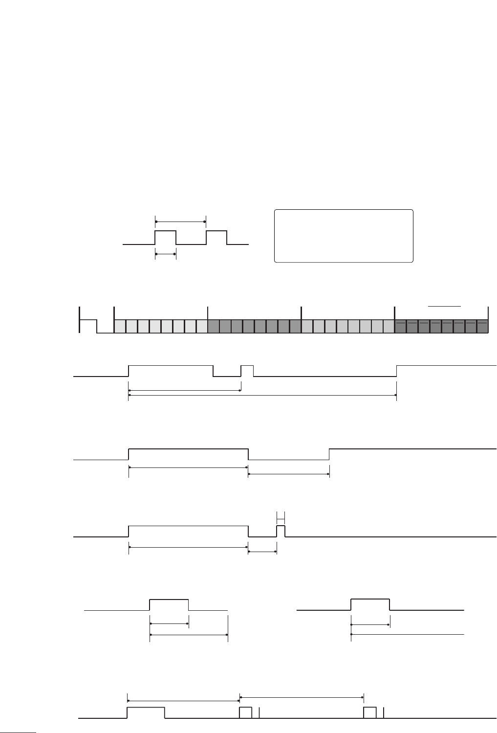
A
Configuration of frame
1st frame
Repeat frame
A
Lead code
A
Repeat code
ABit description
AFrame interval: Tf
The waveform is transmitted as long as a key is depressed.
C0 C1 C2 C3 C4 C5 C6 C7 C0 C1 C2 C3 C4 C5 C6 C7 D0 D1 D2 D3 D4 D5 D6 D7 D0 D1 D2 D3 D4 D5 D6 D7
Lead code Low custom code High custom code Data code Data code
Repeat code Tf
4.5 ms
9 ms
2.25 ms
9 ms
0.55 ms
0.56 ms
1.12 ms
0.56 ms
2.24 ms
Tf Tf
Tf=108ms @455KHz
Bit ”0” Bit ”1”
1. How to Connect
AConnect your wired remote control to the Remote Control port on the set.
2. Remote Control IR Codes
A
Output waveform
Single pulse, modulated with 37.917 KHz signal at 455 KHz
T1
Tc
Carrier frequency
FCAR = 1/TC = fOSC/12
Duty ratio = T1/TC = 1/3
89
APPENDIX
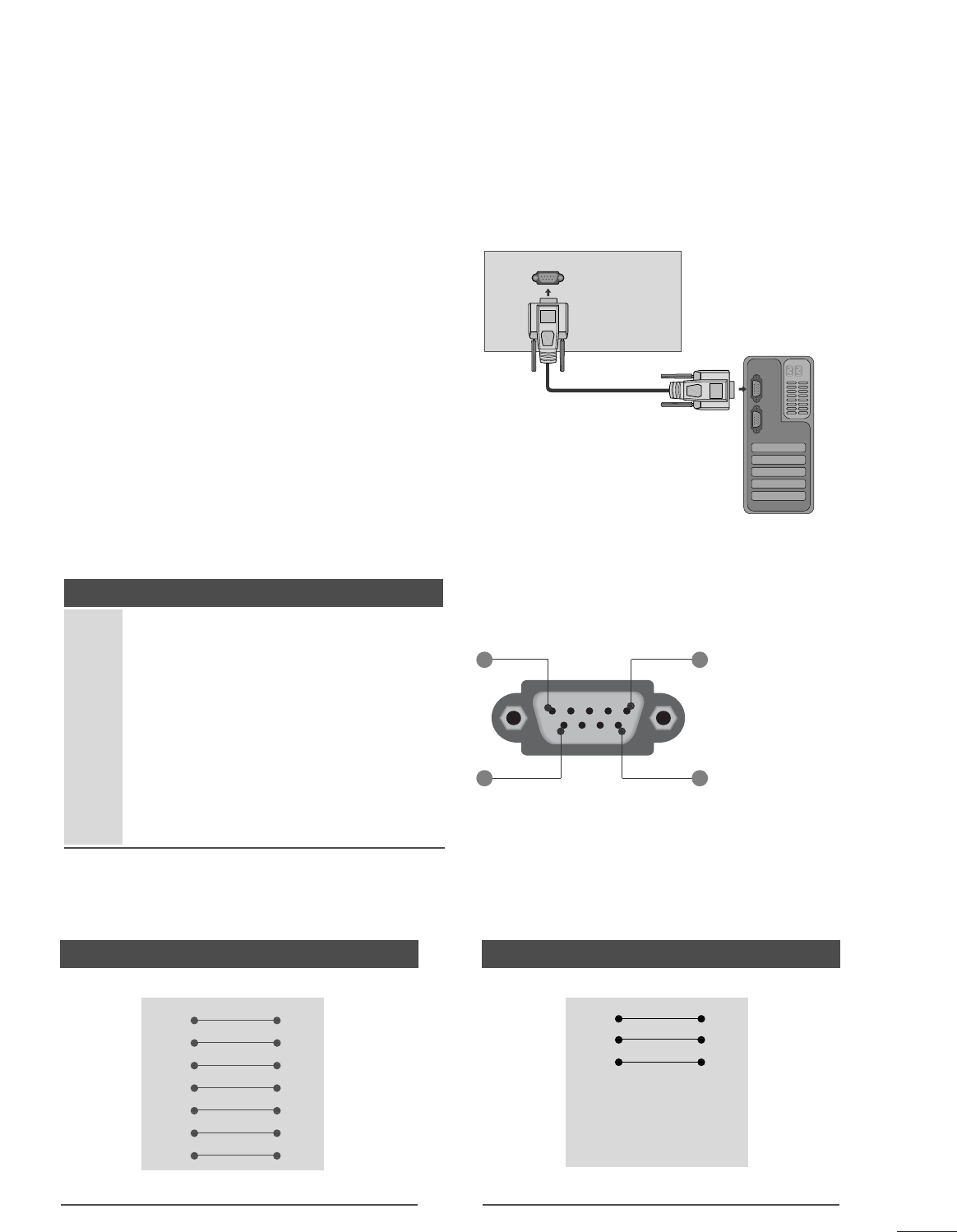
EXTERNAL CONTROL DEVICE SETUP
RS-232C Setup
Connect the RS-232C (serial port) input jack to an
external control device (such as a computer or an A/V
control system) to control the product’s functions exter-
nally.
Connect the serial port of the control device to the RS-
232C jack on the product back panel.
Note: RS-232C on this unit is intended to be used with
third party RS-232C control hardware and software. The
instructions below are provided to help with program-
ming software or to test functionality using telenet soft-
ware. RS-232C connection cables are not supplied with
the product.
Type of Connector; D-Sub 9-Pin Male
No. Pin Name
1 No connection
2 RXD (Receive data)
3 TXD (Transmit data)
4DTR
(DTE side ready)
5 GND
6 DSR (DCE side ready)
7 RTS (Ready to send)
8 CTS (Clear to send)
9 No Connection
RS-232C IN
(CONTROL & SERVICE)
1 5
6 9
RS-232C Configurations
7-Wire Configuration (Serial female-female NULL modem cable)
PC TV
RXD 2 3 TXD
TXD 3 2 RXD
GND 5 5 GND
DTR 4 6 DSR
DSR 6 4 DTR
RTS 7 8 CTS
CTS 8 7 RTS
D-Sub 9 D-Sub 9
3-Wire Configurations(Not standard)
PC TV
RXD 2 3 TXD
TXD 3 2 RXD
GND 5 5 GND
DTR 4 6 DTR
DSR 6 4 DSR
RTS 7 7 RTS
CTS 8 8 CTS
D-Sub 9 D-Sub 9
90
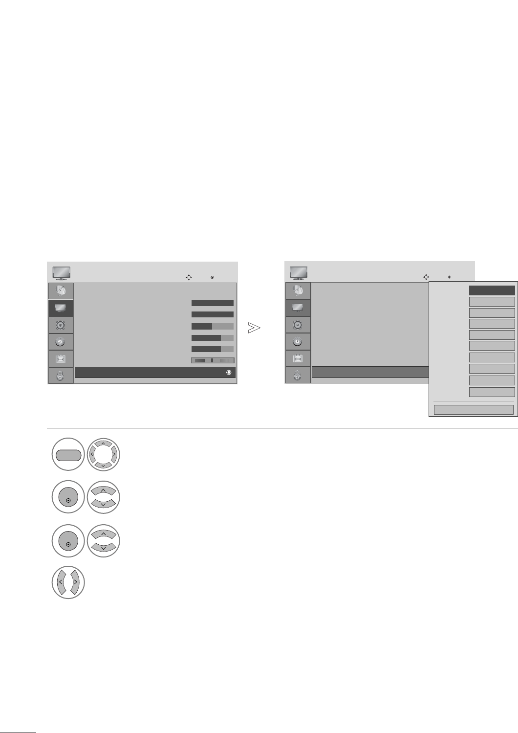
APPENDIX
Use this function to specify a set ID number.
Refer to ‘Real Data Mapping’. p. 93
Set ID
Select OPTION.
2Select Set ID.
3adjust Set ID to choose the desired set ID number.
The adjustment range of SET ID is 1~99.
1
ENTER
ENTER
• Press the MENU button to close the menu window.
• Press the RETURN button to move to the previous menu screen.
Language : English
Input Label
Key Lock : Off
Caption : Off
Set ID : 1
Power Indicator : On
DDC-CI : On
Initial Setting : Home
OPTION
Move Enter
Set ID : 1
Language : English
Input Label
Key Lock : Off
Caption : Off
Set ID : 1
Power Indicator : On
DDC-CI : On
Initial Setting : Home
OPTION
Move Enter
Set ID : 1
F 1G
Close
MENU
91
APPENDIX
Command Reference List
COMMAND1 COMMAND2
19. Channel Tuning
DATA
(Hexadecimal)
COMMAND1 COMMAND2
DATA
(Hexadecimal)
COMMAND1 COMMAND2
DATA00
(Hexadecimal)
DATA01
(Hexadecimal)
DATA02
(Hexadecimal)
DATA03
(Hexadecimal)
DATA04
(Hexadecimal)
DATA05
(Hexadecimal)
physical major major low minor high minor low attribute
program high program low
ma
01. Power k a 00 ~01
02. Input Select x b (Gp.92)
03. Aspect Ratio k c (Gp.92)
04. Screen Mute k d 00 ~01
05. Volume Mute k e 00 ~01
06. Volume Control k f 00 ~64
07. Contrast k g 00 ~64
08. Brightness k h 00 ~64
09. Color k i 00 ~64
10. Tint k j 00 ~64
11. Sharpness k k 00 ~64
12. OSD Select k l 00 ~01
13. Remote Control
Lock Mode
Transmission / Receiving Protocol
Transmission
[Command 1] : First command to control the set.(j, k, m or x)
[Command 2] : Second command to control the set.
[Set ID] : You can adjust the set ID to choose desired set ID
number in Option menu. Adjustment range is 1~99.
When selecting Set ID ‘0’, every connected the set is
controlled. Set ID is indicated as decimal (1~99)on
menu and as Hexa decimal (0x0~0x63)on transmission
/receiving protocol.
[DATA] : To transmit the command data.
Transmit the ‘FF’ data to read status of command.
[Cr] : Carriage Return
ASCII code ‘0x0D’
[ ] : ASCII code ‘space (0x20)’
* In this model, set will not send the status during the standby mode.
OK Acknowledgement
The set transmits ACK (acknowledgement) based on this for-
mat when receiving normal data. At this time, if the data is
data read mode, it indicates present status data. If the data is
data write mode, it returns the data of the PC computer.
* In this model, set will not send the status during the standby mode.
* Data Format
[Command 2] : Use as command.
[Set ID] : Use the small character, if set ID is 10, it will send the ‘0’, ‘a’.
[DATA] : Use the small character, if data is 0 x ab, it will send the ‘a’, ‘b’.
[OK] : Use the large character.
Error Acknowledgement
The set transmits ACK (acknowledgement) based on this for-
mat when receiving abnormal data from non-viable functions
or communication errors.
Data1: Illegal Code
Data2: Not supported function
Data3: Wait more time
* In this model, set will not send the status during the standby mode.
* Data Format
[Command 2] : Use as command.
[Set ID] : Use the small character, if set ID is 10, it will send the ‘0’, ‘a’.
[DATA] : Use the small character, if data is 0 x ab, it will send the ‘a’, ‘b’.
[NG] : Use the large character
[Command1][Command2][ ][Set ID][ ][Data][Cr]
[Command2][ ][Set ID][ ][OK][Data][x]
[Command2][ ][Set ID][ ][NG][Data][x]
14. Treble k r 00 ~64
15. Bass k s 00 ~64
16. Balance k t 00 ~64
17.
Color Temperature
k u 00 ~02
18. Auto Configuration j u (Gp.93)
20. Channel Add/Del m b 00 ~01
21 . K ey m c ( Gp.94)
22. Backlight m g 00 ~64
00 ~01
k m

92
APPENDIX
01. Power (Command: k a)
To control Power On/Off of the set.
Transmission [k][a][ ][Set ID][ ][Data][Cr]
Data 00: Power Off Data 01: Power On
Acknowledgement [a][ ][Set ID][ ][OK/NG][Data][x]
* In a like manner, if other functions transmit ‘FF’ data
based on this format, Acknowledgement data feedback
presents status about each function.
* Note: In this model, set will send the Acknowledge
after power on processing completion.
There might be a time delay between command and
acknowledge.
02. Input Select (Command: x b)
To select input source for set.
Transmission [x][b][ ][Set ID][ ][Data][Cr]
Data 00: DTV (Antenna) Data 01: DTV (Cable)
Data 10: Analog (Antenna) Data 11: Analog (Cable)
Data 20: AV Data 40: Component
Data 60: RGB-PC Data 70:DVI
Data 90: HDMI1 Data 91: HDMI2
Acknowledgement [b][ ][Set ID][ ][OK/NG][Data][x]
03. Aspect Ratio (Command: k c)
To adjust the screen format.
Transmission [k][c][ ][Set ID][ ][Data][Cr]
Data 01: 4:3 06: Set by program
02: 16:9 04: Zoom 1
09: Just scan 05: Zoom 2
Reserved
Acknowledgement [c][ ][Set ID][ ][OK/NG][Data][x]
04. Screen Mute (Command: k d)
To select screen mute on/off.
Transmission [k][d][ ][Set ID][ ][Data][Cr]
Data 00: Screen mute off (Picture on)
Data 01: Screen mute on (Picture off)
Acknowledgement [d][ ][Set ID][ ][OK/NG][Data][x]
05. Volume Mute (Command: k e)
To control volume mute on/off.
You can also adjust mute using the MUTE button on
remote control.
Transmission [k][e][ ][Set ID][ ][Data][Cr]
Data 00: Volume mute on (Volume off)
Data 01: Volume mute off (Volume on)
Acknowledgement [e][ ][Set ID][ ][OK/NG][Data][x]
06. Volume Control (Command: k f)
To adjust volume.
You can also adjust volume with the volume buttons on
remote control.
Transmission [k][f][ ][Set ID][ ][Data][Cr]
Data Min: 00 ~Max: 64 (*transmit by Hexadecimal code)
*Refer to ‘Real data mapping’. See page 93.
Acknowledgement [f][ ][Set ID][ ][OK/NG][Data][x]
07. Contrast (Command: k g)
To adjust screen contrast.
You can also adjust contrast in the PICTURE menu.
Transmission [k][g][ ][Set ID][ ][Data][Cr]
Data Min: 00 ~Max: 64 (*transmit by Hexadecimal code)
*Refer to ‘Real data mapping’. See page 93.
Acknowledgement [g][ ][Set ID][ ][OK/NG][Data][x]
08. Brightness (Command: k h)
To adjust screen brightness.
You can also adjust brightness in the PICTURE menu.
Transmission [k][h][ ][Set ID][ ][Data][Cr]
Data Min: 00 ~Max: 64 (*transmit by Hexadecimal code)
*Refer to ‘Real data mapping’. See page 93.
Acknowledgement [h][ ][Set ID][ ][OK/NG][Data][x]
09. Color (Command: k i)
To adjust screen color.
You can also adjust color in the PICTURE menu.
Transmission [k][i][ ][Set ID][ ][Data][Cr]
Data Min: 00 ~Max: 64 (*transmit by Hexadecimal code)
*Refer to ‘Real data mapping’. See page 93.
Acknowledgement [i][ ][Set ID][ ][OK/NG][Data][x]
10. Tint (Command: k j)
To adjust screen tint.
You can also adjust tint in the PICTURE menu.
Transmission [k][j][ ][Set ID][ ][Data][Cr]
Data Red: 00 ~Green: 64 (*transmit by Hexadecimal code)
*Refer to ‘Real data mapping’. See page 93.
Acknowledgement [ j ][ ][Set ID][ ][OK/NG][Data][x]
11. Sharpness (Command: k k)
To adjust screen sharpness.
You can also adjust sharpness in the PICTURE menu.
Transmission [k][k][ ][Set ID][ ][Data][Cr]
Data Min: 00 ~Max: 64 (*transmit by Hexadecimal code)
*Refer to ‘Real data mapping’. See page 93.
Acknowledgement [k][ ][Set ID][ ][OK/NG][Data][x]
93
APPENDIX
12. OSD Select (Command: k l)
To select OSD (On Screen Display) on/off.
Transmission [k][l][ ][Set ID][ ][Data][Cr]
Data 00: OSD off Data 01: OSD on
Acknowledgement [l][ ][Set ID][ ][OK/NG][Data][x]
13. Remote Control Lock Mode (Command: k m)
To lock the remote control and the front panel controls
on the set.
Transmission [k][m][ ][Set ID][ ][Data][Cr]
Data 00: Lock off Data 01: Lock on
Acknowledgement [m][ ][Set ID][ ][OK/NG][Data][x]
If you’re not using the remote control and front panel
controls on the TV, use this mode. When main power is
on/off, remote control lock is released.
14. Treble (Command: k r)
To adjust treble.
You can also adjust treble in the AUDIO menu.
Transmission [k][r][ ][Set ID][ ][Data][Cr]
Data Min: 00 ~Max: 64 (*transmit by Hexadecimal code)
*Refer to ‘Real data mapping’ as shown.
Acknowledgement [r][ ][Set ID][ ][OK/NG][Data][x]
15. Bass (Command: k s)
To adjust bass.
You can also adjust bass in the AUDIO menu.
Transmission [k][s][ ][Set ID][ ][Data][Cr]
Data Min: 00 ~Max: 64 (*transmit by Hexadecimal code)
*Refer to ‘Real data mapping’ as shown.
Acknowledgement [s][ ][Set ID][ ][OK/NG][Data][x]
16. Balance (Command: k t)
To adjust balance.
You can also adjust balance in the AUDIO menu.
Transmission [k][t][ ][Set ID][ ][Data][Cr]
Data Min: 00 ~Max: 64 (*transmit by Hexadecimal code)
*Refer to ‘Real data mapping’ as shown.
Acknowledgement [t][ ][Set ID][ ][OK/NG][Data][x]
17. Color Temperature (Command: k u)
To adjust color temperature.
You can also adjust color temperature in the PICTURE menu.
Transmission [k][u][ ][Set ID][ ][Data][Cr]
Data 00: Medium 01: Cool 02: Warm
Acknowledgement [u][ ][Set ID][ ][OK/NG][Data][x]
18. Auto Configuration (Command: j u)
To adjust picture position and minimize image shaking
automatically. Auto configuration only works in RGB-PC
mode.
Transmission [ j ][u][ ][Set ID][ ][Data][Cr]
Data 01: To set
Acknowledgement [u][ ][Set ID][ ][OK/NG][Data][x]
19. Channel Tuning (Command: m a)
To tune channel to following physical/major/minor number.
Transmission [m][a][ ][Set ID][ ][Data00][ ][Data01]
[ ][Data02][ ][Data03][ ][Data04][ ][Data05][Cr]
Digital channels have a Physical, Major, and Minor channel
number. The Physical number is the actual digital channel
number, the Major is the number that the channel should
be mapped to, and the Minor is the sub-channel. Since
the ATSC tuner automatically maps the channel to the
Major number, the Physical number is not required when
sending a command.
Data 00: Physical Channel Number
NTSC air: 02~45, NTSC cable: 01, 0E~7D
ATSC air: 01~45, ATSC cable: 01~87
Data 01 & 02: Major Channel Number
Data 01: High byte Data 02: Low byte
Two bytes are available for the Major and Minor, nor-
mally only the second byte is used.
Data 03 & 04: Minor Channel Number
Not needed for NTSC.
*Real data mapping
0 : Step 0
A : Step 10 (SET ID 10)
F : Step 15 (SET ID 15)
10 : Step 16 (SET ID 16)
63 : Step 99 (SET ID 99)
64 : Step 100
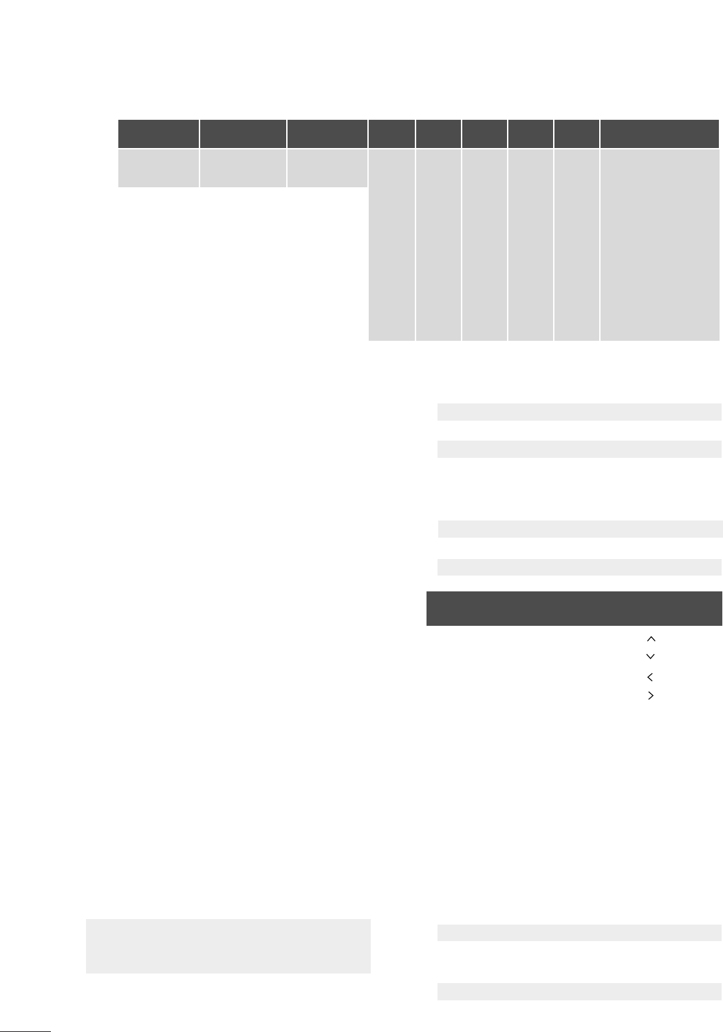
94
APPENDIX
Data5:
The table above lists the binary code which must be
converted to Hexadecimal before sending. For example:
The binary code to tune the sub source to an NTSC
cable channel is “1000 0001”, which translates to “81”
in Hex.
* 7th bit : For which source do you want to change the
channel.
* 6th bit: Use a two part or one part channel. Most cases
just use 0 since it’s ignored when using NTSC.
* 5th bit: Use 0 with NTSC since it can only use the phys-
ical channel number. Normally use 1 for ATSC since most
times it doesn’t matter what the physical number is.
* 4th bit: Set to 0.
* 3-0 bits: Choose signal type.
* Tune Command Examples:
1. Tune to the analog (NTSC) cable channel 35.
Data 00 = Physical of 35 = 23
Data 01 & 02 = No Major = 00 00
Data 03 & 04 = No Minor = 00 00
Data 05 = 0000 0001 in binary = 01
Total = ma 00 23 00 00 00 00 01
2. Tune to the digital (ATSC) local channel 30-3.
Data 00 = Don’t know Physical = 00
Data 01 & 02 = Major is 30 = 00 1E
Data 03 & 04 = Minor is 3 = 00 03
Data 05 = 0010 0010 in binary = 22
Total = ma 00 00 00 1E 00 03 22
Acknowledgement[a][ ][Set ID][
][OK][Data00][Data01]
[Data02][Data03][Data04][x][a][ ][Set ID]
[ ][NG][Data00][x]
20. Channel Add/Del (Command: m b)
To add and delete the channels.
Transmission [m][b][ ][Set ID][ ][Data][Cr]
Data 00: Channel Delete Data 01: Channel Add
Acknowledgement [b][ ][Set ID][ ][OK/NG][Data][x]
21. Key (Command: m c)
To send IR remote key code.
Transmission [m][c][ ][Set ID][ ][Data][Cr]
Acknowledgement [c][ ][Set ID][ ][OK/NG][Data][x]
22. Backlight (Command: m g)
To adjust screen backlight.
Transmission [m][g][ ][Set ID][ ][Data][Cr]
Data Min:00 ~Max:64 (*transmit by Hexadecimal code)
*Refer to ‘Real data mapping’. See page 93.
Acknowledgement [g][ ][Set ID][ ][OK/NG][Data][x]
Step
NTSC Air
NTSC Cable
ATSC Air
ATSC Cable_std
ATSC Cable_hrc
ATSC Cable_irc
ATSC cable_auto
Reserved
...
Reserved
1
0
0
1
1
0
0
1
1
x
1
2
0
0
0
0
1
1
1
1
x
1
3
0
0
0
0
0
0
0
0
x
1
4
x
x
x
x
x
x
x
x
x
x
Reserved
5
0
1
Use
No Use
Using Physical
Channel
6
0
1
Two
One
Two/One
Part Channel
7
0
1
Main
Sub
Main/Sub
Picture 0
0
1
0
1
0
1
0
1
x
1
Code
(Hexa) Remote control Code
(Hexa) Remote control
0F TV/PC
0B INPUT
08 POWER
79 RATIO
10-19 Number Key 0-9
4C - (Dash)
09 MUTE
02 VOL +
03 VOL -
00 CH +
01 CH -
1E FAV
39 CC
40
41
07
06
44 ENTER
43 MENU
45 Q.MENU
52 SOUND
4D PICTURE
5B RETURN
0A SAP
1A FLASHBK

Regulatory Information cont.
FCC Compliance Statement
This equipment has been tested and found to comply
within the limits of a Class B digital device pursuant to Part
15 of the FCC Rules. These limits are designed to provide
reasonable protection against harmful interference in a
residential installation.
This equipment generates, uses, and can radiate radio
frequency energy and if not installed and used in
accordance with the instructions, may cause harmful
interference to radio communications. However, there is
no guarantee that interference will not occur in a particular
installation.
If this equipment does cause harmful interference to radio
or television reception (which can be determined by
turning the equipment on and off), the user is encouraged
to try to correct the interference by using one or more of
the following measures:
Reorient or relocate the receiving antenna.
Increase the separation between the equipment and
the receiver.
Connect the equipment into an outlet on a circuit
different from that to which the receiver is connected.
Consult the dealer or an experienced radio/TV
technician for help.
Caution: Changes or modifications not expressly approved
by the party responsible for compliance could void the
user's (or your) authority to operate the equipment. Only
peripherals (digital input/output devices, terminals, printers,
etc.) certified to comply with the Class B limits may be
attached to this monitor. Operation with non-certified
peripherals is likely to result in interference to radio and TV
reception. Only shielded signal cables may be used with
this System.
Canadian DOC Notice
This Class B digital apparatus meets all requirements of
the Canadian Interference-Causing Equipment
Regulations. Cet appareil numérique de la classe B
respecte toutes les exigences du Règlement sur le
matériel brouilleur du Canada.
CE Conformity Notice
(for Europe)
Products with the “CE” Marking comply with the EMC
Directive(89/336/EEC) and LOW VOLTAGE Directive
(73/23/EEC) issued by the Commission of the European
Community.
Compiance with these directives implies conformity to the
following European Norms :
• EN 55022 ; Radio Frequency Interference
• EN 55024 ; Electromagnetic Immunity
• EN 61000-3-2 ; Power Line Harmonics
• EN 61000-3-3 ; Voltage Fluctuations
• EN 60950-1 ; Product Safety
Low Radiation Compliance (MPR II)
This monitor meets one of the strictest guidelines available
today for low radiation emissions, offering the user extra
shielding and an antistatic screen coating. These
guidelines, set forth by a government agency in Sweden,
limit the amount of emission allowed in the Extremely Low
Frequency (ELF) and Very Low Frequency (VLF)
electromagnetic range.
01
NOTICE
The regulations are applied only to the products with the
ID LABEL indicating specific requirements.
NOTICE
The regulations are applied only to the products with the
ID LABEL indicating specific requirements.
NOTICE
The regulations are applied only to the products with the
ID LABEL indicating specific requirements.
TCO'99 (TCO'99 applied model only)
Congratulations!
You have just purchased a TCO’99 approved and labelled
product! Your choice has provided you with a product
developed for professional use. Your purchase has also
contributed to reducing the burden on the environment and
also to the further development of environmentally
adapted electronics products.

Regulatory Information cont.
02
Why do we have environmentally labelled computers?
In many countries, environmental labelling has become an
established method for encouraging the adaptation of
goods and services to the environment. With the growing
manufacture and usage of electronic equipment
throughout the world, there is a recognized concern for the
materials and substances used by electronic products
with regards to their eventual recycling and disposal. By
proper selection of these materials and substances, the
impact on the environment can be minimized.
There are also other characteristics of a computer, such as
energy consumption levels, that are important from the
viewpoints of both the work (internal) and natural (external)
environments. Electronic equipment in offices is often left
running continuously, resulting in unnecessary
consumption of large amounts of energy and additional
power generation. From the standpoint of carbon dioxide
emissions alone, it is vital to save energy.
What does labelling involve?
The product meets the requirements for the TCO’99
scheme which provides for international and environmental
labelling of personal computers and/or displays.
The labelling scheme was developed as a joint effort by the
TCO (The Swedish Confederation of Professional
Employees), Svenska Naturskyddsforeningen
(The Swedish Society for Nature Conservation) and
Statens Energimyndighet (The Swedish National
Energy Administration).
Approval requirements cover a wide range of issues:
ecology, ergonomics, emission of electrical and magnetical
fields, energy consumption and electrical safety.
Ecological criteria impose restrictions on the presence and
use of heavy metals, brominated and chlorinated flame
retardants, and other substances. The product must be
prepared for recycling and the manufacturing site(s) shall
be certified according to ISO14001 or EMAS registered.
Energy requirements include a demand that the system
unit and/or display, after a certain period of inactivity,
shall reduce its power consumption to a lower level in one
or more stages. The length of time to reactivate the system
unit shall be reasonable for the user.
Labelled products must meet strict environmental
demands, for example, in respect of the reduction of
electrical and magnetical fields as well as work load and
visual ergonomics.
Below you will find a brief summary of the ecological
requirements met by this product. The complete
ecological criteria document can be found at TCO
Development’s website http://www.tcodevelopment.com
or may be ordered from:
TCO Development
SE-114 94 STOCKHOLM, Sweden
Fax: +46 8 782 92 07
Email : development@tco.se
Information regarding TCO’99 approved and labelled
products may also be obtained at
http://www.tcodevelopment.com
Ecological requirements
Flame retardants
Flame retardants may be present in printed wiring board
laminates, cables, and housings. Their purpose is to
prevent, or at least to delay the spread of fire. Up to 30%
by weight of the plastic in a computer casing can consist of
flame retardant substances. Many flame retardants
contain bromine or chlorine, and these flame retardants
are chemically related to PCBs (polychlorinated
biphenyls). Both the flame retardants containing bromine
or chlorine and the PCBs are suspected of giving rise to
health effects, including reproductive damage in fish-
eating birds and mammals, due to the bio-accumulative*
processes when not disposed of in accordance with strict
standards for disposal.
TCO’99 requires that plastic components weighing more
than 25 grams shall not contain flame retardants with
organically bound bromine or chlorine. Flame retardants
are allowed in the printed wiring board laminates due to
the lack of commercially available alternatives.
Cadmium**
Cadmium is present in rechargeable batteries and in the
colour-generating layers of certain computer displays.
TCO’99 requires that batteries, the colour-generating
layers of display screens, and the electrical or electronics
components shall not contain any cadmium.
Mercury**
Mercury is sometimes found in batteries, relays and
switches. TCO’99 requires that batteries shall not contain
any mercury. It also demands that mercury is not present
in any of the electrical or electronics components
associated with the labelled unit. There is however one
Regulatory Information cont.
03
exception. Mercury is, for the time being, permitted in the
back light system of flat panel monitors as there today is
no commercially available alternative. TCO aims on
removing this exception when a mercury free alternative is
available.
Lead**
Lead can be found in picture tubes, display screens,
solders and capacitors. TCO’99 permits the use of lead
due to the lack of commercially available alternatives, but
in future requirements TCO Development aims at
restricting the use of lead.
_____________________________________________
* Bio-accumulative is defined as substances which
accumulate in living organisms.
**Lead, Cadmium and Mercury are heavy metals
which are bio-accumulative.
TCO’03
(TCO’03 applied model only)
Congratulations!
The display you have just purchased carries the TCO’03
Displays label.
This means that your display is designed,manufactured
and tested according to some of the strictest quality and
environmental requirements in the world. This makes for a
high performance product, designed with the user in focus
that also minimizes the impact on our natural environment.
Some of the features of the TCO’03 Display requirements:
Ergonomics
• Good visual ergonomics and image quality in order to
improve the working environment for the user and to
reduce sight and strain problems. Important
parameters are luminance, contrast, resolution,
reflectance, colour rendition and image stability.
Energy
• Energy-saving mode after a certain time – beneficial
both for the user and the environment
• Electrical safety
Emissions
• Electromagnetic fields
• Noise emissions
Ecology
• The product must be prepared for recycling and the
manufacturer must have a certified environmental
management system such as EMAS or ISO 14 001
• Restrictions on
chlorinated and brominated flame retardants and
polymers
heavy metals such as cadmium, mercury and lead.
The requirements included in this label have been
developed by TCO Development in co-operation with
scientists, experts, users as well as manufacturers all over
the world. Since the end of the 1980s TCO has been
involved in influencing the development of IT equipment in
a more user-friendly direction. Our labelling system started
with displays in 1992 and is now requested by users and
IT-manufacturers all over the world.
For more information, please visit
www.tcodevelopment.com
Information for Environmental Preservation
LGE. announced the 'LG Declaration for a Cleaner
Environment' in 1994, and this ideal has served as a
guiding managerial principle ever since. The Declaration is
a foundation that has allowed us to undertake
environmentally friendly activities in careful consideration
of economic, environmental, and social aspects.
We promote activities for environmental preservation, and
we specifically develop our products to embrace the
concept of environment-friendly.
We minimize the hazardous materials contained in our
products. For example, there is no cadmium to be found in
our monitors.
Information for recycling
This monitor may contain parts which could be hazardous
to the environment. It is important that this monitor be
recycled after use.
LGE. handles all waste monitors through an
environmentally acceptable recycling method. There are
several take-back and recycling systems currently in
English
Regulatory Information cont.
04
operation worldwide. Many parts will be reused and
recycled, while harmful substances and heavy metals are
treated by an environmentally friendly method.
If you want to find out more information about our
recycling program, please contact your local LG vendor or
a corporate representative of LG.
We set our vision and policies on a cleaner world by
selecting the issue of the global environment as a task for
corporate improvement. Please visit our website for more
information about our ‘green’ policies.
http://www.lge.com/about/environment/html/Recycling.jsp
Informationen zur Erhaltung der Umwelt
Im Jahr 1994 verkündete LGE die 'LG Declaration for a
Cleaner Environment' (LG Erklärung für eine sauberere
Umwelt). Seitdem dient dieses Ideal als führendes Prinzip
des Unternehmens. Diese Erklärung war die Basis für die
Durchführung von
umweltfreundlichen Aktivitäten, wobei wirtschaftliche,
umweltbezogene und soziale Aspekte in die
Überlegungen mit einbezogen wurden.
Wir fördern Aktivitäten zum Schutz der Umwelt und die
Entwicklung unserer Produkte ist darauf ausgerichtet,
unserem Konzept bezüglich Umweltfreundlichkeit gerecht
zu werden.
Wir sind darauf bedacht, den Anteil der in unseren
Produkten enthaltenen schädlichen Materialien zu
minimieren. So ist in unseren Monitoren beispielsweise
kein Kadmium zu finden.
Informationen zum Thema Recycling
Dieser Monitor enthält Teile, die umweltschädlich sein
können. Es ist unbedingt erforderlich, dass der Monitor
recycelt wird, nachdem er außer Dienst gestellt wurde.
Bei LGE. werden alle ausrangierten Monitore in einem
unter umweltbezogenen Aspekten geeigneten Verfahren
recycelt. Augenblicklich sind weltweit mehrere
Rücknahme- und Recyclingsysteme im Einsatz. Viele
Teile werden wieder verwendet und recycelt. Schädliche
Substanzen und Schwermetalle werden durch
umweltverträgliche Verfahren behandelt.
Falls Sie mehr über unser Recyclingprogramm erfahren
möchten, wenden Sie sich bitte an Ihren lokalen LG-
Händler oder einen Unternehmensvertreter von LG.
Wir richten unsere Firmenpolitik auf eine sauberere
Umwelt hin aus, indem wir umweltspezifische Aspekte als
wichtigen Punkt in die Weiterentwicklung unseres
Unternehmens einfließen lassen. Zusätzliche
Informationen über unsere ‘grüne’ Firmenpolitik erhalten
Sie auf unserer Website.
http://www.lge.com/about/environment/html/Recycling.jsp
Information sur la protection del’environnement
LGE. a publié sa 'Déclaration en faveur d’un
environnement plus propre' en 1994 et celle-ci est restée,
depuis lors, un principe directeur de notre entreprise.
Cette déclaration a servi de base à notre réflexion et nous
a permis de prendre en compte à la fois les aspects
économiques et sociaux de nos activités, tout en
respectant l’environnement.
Nous encourageons les activités en faveur de la
préservation de l’environnement et c’est dans cet esprit
que nous développons nos produits : nous réduisons au
minimum les matières dangereuses qui entrent dans leur
composition et l’on ne trouve pas de cadmium, par
exemple, dans nos moniteurs.
Information sur le recyclage
Ce moniteur peut contenir des composants qui présentent
un risque pour l’environnement. Il est donc important que
celui-ci soit recyclé après usage.
LGE. traite les moniteurs en fin de cycle conformément à
une méthode de recyclage respectueuse de
l’environnement. Nous reprenons nos produits et les
recyclons dans plusieurs sites répartis dans le monde
entier. De nombreux composants sont réutilisés et
recyclés, et les matières dangereuses, ainsi que les
métaux lourds, sont traités selon un procédé écologique.
Si vous souhaitez plus de renseignements sur notre
programme de recyclage, veuillez contacter votre
revendeur LG ou un l’un de nos représentants.
Nous voulons agir pour un monde plus propre et croyons
au rôle de notre entreprise dans l’amélioration de
l’environnement. Pour plus de renseignements sur notre
politique “verte”, rendez visite à notre site :
http://www.lge.com/about/environment/html/Recycling.jsp
Deutsch
Français
05
Regulatory Information cont.
Informazioni per la tutela dell’ambiente
La LGE. ha annunciato nel 1994 la cosiddetta 'LG
Declaration for a Cleaner Environment' (Dichiarazione di
LG a favore di un ambiente più pulito), un ideale che da
allora funge da principio ispiratore della gestione
aziendale. La dichiarazione rappresenta il fondamento che
consente di intraprendere attività a favore dell'ambiente
tenendo conto degli aspetti economici, ambientali e
sociali.Noi della LG, promuoviamo attività a favore della
tutela dell'ambiente sviluppando appositamente i nostri
prodotti per cogliere il concetto del rispetto dell’ambiente
riducendo i materiali dannosi presenti nei nostri prodotti.
Ad esempio nei nostri monitor non è presente il cadmio.
Informazioni per il riciclaggio
Il monitor può presentare componenti che potrebbero
risultare eventualmente dannosi per l'ambiente. È
importante che il monitor sia riciclato al termine del suo
utilizzo.
La LGE. gestisce tutti i monitor di rifiuto con un metodo di
riciclaggio soddisfacente dal punto di vista ambientale. In
tutto il mondo sono attualmente in funzione numerosi
sistemi di riciclaggio e recupero. I diversi componenti sono
riutilizzati e riciclati, mentre le sostanze dannose e i metalli
pesanti vengono trattati con un metodo rispettoso
dell’ambiente.
Se si desiderano maggiori informazioni in merito al
programma di riciclaggio, è consigliabile rivolgersi al
proprio rivenditore LG o ad un rappresentante aziendale
della LG.
Noi della LG impostiamo la nostra visione e le nostre
politiche a favore di un mondo più pulito ponendo la
questione dell'ambiente dal punto di vista globale come
una mansione rivolta al miglioramento della nostra
azienda. Vi invitiamo a visitare il nostro sito internet per
ulteriori informazioni sulla nostra politica “verde”.
http://www.lge.com/about/environment/html/Recycling.jsp
Información para la conservación
medioambiental
LGE. presentó la 'Declaración para un entorno más limpio
de LG' en 1994 y este ideal ha servido para guiar nuestros
principios empresariales desde entonces. La Declaración
es la base que nos ha permitido llevar a cabo tareas que
respetan el medio ambiente siempre teniendo en cuenta
aspectos sociales,
económicos y medioambientales.
Promocionamos actividades orientadas a la conservación
del medio ambiente y desarrollamos nuestros productos
específicamente para que se ajusten a la filosofía que
protege el entorno.
Reducimos al máximo el uso de materiales de riesgo en
nuestros productos. Un ejemplo de ello es la ausencia
total de cadmio en nuestros monitores.
Información para el reciclaje
Este monitor puede contener piezas que entrañen riesgos
medioambientales. Es importante reciclar este monitor
después de su utilización.
LGE. trata todos los monitores usados siguiendo un
método de reciclaje que no daña al entorno. Contamos
con diversos sistemas de recuperación y reciclaje que
funcionan a nivel mundial en la actualidad. Es posible
reciclar y reutilizar muchas de las piezas, mientras que las
sustancias dañinas y los metales pesados se tratan
siguiendo un método que no perjudique al medio
ambiente. Si desea obtener más información acerca del
programa de reciclaje, póngase en contacto con su
proveedor local de LG o con un representante empresarial
de nuestra marca.
Basamos nuestra visión y nuestras políticas en un mundo
más limpio y para ellos optamos por un entorno global
como tarea principal de nuestra evolución como empresa.
Visite nuestra página Web para obtener más información
sobre nuestras políticas ecológicas.
http://www.lge.com/about/environment/html/Recycling.jsp
Informações relacionadas à preservação
ambiental
A LGE. anunciou a 'LG Declaration for a Cleaner
Environment' (Declaração da LG para um ambiente mais
limpo) em 1994 e esse ideal tem servido desde então
como um princípio administrativo de orientação. A
Declaração é a base que nos tem permitido realizar
atividades favoráveis ao ambiente com consideração
atenta aos aspectos econômicos, ambientais e sociais.
Promovemos atividades de preservação ambiental e
desenvolvemos nossos produtos para englobar
Italiano
Espanõl
Português
06
Regulatory Information cont.
especificamente o conceito de favorável ao ambiente.
Reduzimos os materiais perigosos contidos em nossos
produtos. Por exemplo, não há cádmio em nossos
monitores.
Informações relacionadas à reciclagem
Este monitor pode conter peças que podem representar
riscos ao ambiente. É importante que ele seja reciclado
após o uso.
A LGE. cuida de todos os monitores descartados através
de um método de reciclagem agradável ao ambiente. Há
vários sistemas de devolução e reciclagem atualmente
em operação no mundo. Muitas peças serão reutilizadas
e recicladas e as substâncias nocivas e os metais
pesados passarão por tratamento através de um método
favorável ao ambiente.
Para obter mais informações sobre nosso programa de
reciclagem, entre em contato com seu fornecedor LG
local ou com um representante corporativo da LG.
Definimos nossa visão e nossas políticas relacionadas a
um mundo mais limpo selecionando a questão do
ambiente global como uma tarefa de aprimoramento
corporativo. Visite nosso site para obter mais informações
sobre nossas políticas de meio ambiente.
http://www.lge.com/about/environment/html/Recycling.jsp
Informatie met betrekking tot het behoud van
het milieu
LGE. publiceerde in 1994 de 'LG Declaration for a Cleaner
Environment' (de LG-verklaring met betrekking tot een
schoner milieu). Deze verklaring en het ideaal van een
schoner milieu fungeren sindsdien als een bestuurlijke
leidraad voor onze onderneming. Op basis van deze
verklaring ontplooien wij milieuvriendelijke activiteiten,
waarbij er zowel met sociale en economische aspecten,
als met milieuaspecten zorgvuldig rekening wordt
gehouden.
Wij ondersteunen activiteiten die zijn gericht op het
behoud van het milieu en wij houden bij het ontwikkelen
onze producten specifiek rekening met de
milieuvriendelijkheid van onze producten.
Wij minimaliseren het gebruik van schadelijke stoffen in
onze producten. Er wordt bijvoorbeeld geen cadmium
verwerkt in onze monitors.
Nederlands
Informatie met betrekking tot recycling
Deze monitor bevat materialen die schadelijk zouden
kunnen zijn voor het milieu. Het is belangrijk dat deze
monitor aan het einde van zijn levensduur wordt
gerecycled.
LGE. verwerkt alle afvalmonitors via een milieuvriendelijke
recyclingmethode. Hiervoor worden er momenteel
wereldwijd verscheidene inname- en recyclingsystemen
gehanteerd. Een groot aantal onderdelen wordt opnieuw
gebruikt en gerecycled, waarbij schadelijke stoffen en
zware metalen volgens een milieuvriendelijke methode
worden verwerkt.
Voor meer informatie over ons recyclingprogramma kunt u
contact opnemen met uw plaatselijke LG-
vertegenwoordiger of een LG-vestiging.
Onze visie en ons beleid met betrekking tot een schonere
wereld vloeien voort uit het feit dat wij het milieu hebben
aangemerkt als een onderwerp dat speciale aandacht
verdient binnen onze onderneming. Bezoek onze website
voor meer informatie over ons 'groene' beleid.
http://www.lge.com/about/environment/html/Recycling.jsp
»ÌÙÓχˆËˇ ÔÓ Óı‡Ì ÓÍÛʇ˛˘ÂÈ Ò‰˚
¬ 1994 „Ó‰Û ÍÓÔÓ‡ˆËˇ LGE ÓÔÛ·ÎËÍÓ‚‡Î‡
'ƒÂÍ·‡ˆË˛ LG ÔÓ Óı‡Ì ÓÍÛʇ˛˘ÂÈ Ò‰˚',
ÍÓÚÓ‡ˇ Ò ÚÂı ÔÓ ÒÎÛÊËÚ ÓÒÌÓ‚Ì˚Ï ÔË̈ËÔÓÏ
ÛÔ‡‚ÎÂÌˡ. Õ‡ ÓÒÌÓ‚Â ˝ÚÓÈ ‰ÂÍ·‡ˆËË Ï˚ ÒÏÓ„ÎË
Ô‰ÔËÌˇÚ¸ ‰ÂÈÒڂˡ, Ó·ÂÒÔ˜˂‡˛˘ËÂ
·ÂÁÓÔ‡ÒÌÓÒÚ¸ ÓÍÛʇ˛˘ÂÈ Ò‰˚, Û‰ÂΡˇ ÔË ˝ÚÓÏ
‰ÓÎÊÌÓ ‚ÌËχÌË ˝ÍÓÌÓÏ˘ÂÒÍËÏ, ˝ÍÓÎӄ˘ÂÒÍËÏ Ë
ÒӈˇθÌ˚Ï ‡ÒÔÂÍÚ‡Ï.
Ã˚ ÒÚËÏÛÎËÛÂÏ ‰ÂˇÚÂθÌÓÒÚ¸ ÔÓ Óı‡ÌÂ
ÓÍÛʇ˛˘ÂÈ Ò‰˚, Û‰ÂΡˇ ÓÒÓ·Ó ‚ÌËχÌËÂ
‡Á‡·ÓÚÍ ̇¯ÂÈ ÔÓ‰Û͈ËË ‚ ÒÓÓÚ‚ÂÚÒÚ‚ËË Ò
ÍÓ̈ÂÔˆËÂÈ ˝ÍÓÎӄ˘ÂÒÍÓÈ ·ÂÁÓÔ‡ÒÌÓÒÚË.
Ã˚ Ò‚Ó‰ËÏ Í ÏËÌËÏÛÏÛ ÒÓ‰ÂʇÌË ÓÔ‡ÒÌ˚ı
‚¢ÂÒÚ‚ ‚ ̇¯ÂÈ ÔÓ‰Û͈ËË. Õ‡ÔËÏÂ, ‚ ̇¯Ëı
ÏÓÌËÚÓ‡ı ‚˚ Ì ̇ȉÂÚ ͇‰Ïˡ.
»ÌÙÓχˆËˇ ÔÓ ÛÚËÎËÁ‡ˆËË ÓÚıÓ‰Ó‚
›ÚÓÚ ÏÓÌËÚÓ ÏÓÊÂÚ ÒÓ‰Âʇڸ ÍÓÏÔÓÌÂÌÚ˚,
ÍÓÚÓ˚ ÏÓ„ÛÚ Ì‡ÌÂÒÚË Û˘Â· ÓÍÛʇ˛˘ÂÈ Ò‰Â.
Russian
07
Regulatory Information cont.
EPA
(EPA applied model only)
ENERGY STAR
is a set of power-saving guidelines
issued by the U.S. Environmental Protection
Agency(EPA).
NOM MARK (Mexico only)
ÕÂÓ·ıÓ‰ËÏÓ ÛÚËÎËÁËÓ‚‡Ú¸ ÏÓÌËÚÓ ÔÓÒÎÂ
ËÒÔÓθÁÓ‚‡Ìˡ.
KÓÔÓ‡ˆËˇ LGE Ô‡·‡Ú˚‚‡ÂÚ ‚Ò ·‡ÍÓ‚‡ÌÌ˚Â
ÏÓÌËÚÓ˚ Ò ÔÓÏÓ˘¸˛ ˝ÍÓÎӄ˘ÂÒÍË ÔËÂÏÎÂÏÓ„Ó
ÏÂÚÓ‰‡ ÛÚËÎËÁ‡ˆËË ÓÚıÓ‰Ó‚. œÓ ‚ÒÂÏÛ ÏËÛ
‰ÂÈÒÚ‚Û˛Ú ÒËÒÚÂÏ˚ ÛÚËÎËÁ‡ˆËË ÓÚıÓ‰Ó‚ Ë ‚ÓÁ‚‡Ú‡
ËÒÔÓθÁÓ‚‡ÌÌÓÈ ÔÓ‰Û͈ËË. ÃÌÓ„Ë ÍÓÏÔÓÌÂÌÚ˚
·Û‰ÛÚ ‚ÚÓ˘ÌÓ ËÒÔÓθÁÓ‚‡Ì˚ Ë ÛÚËÎËÁËÓ‚‡Ì˚, ‚ ÚÓ
‚ÂÏˇ Í‡Í ‚‰Ì˚ ‚¢ÂÒÚ‚‡ Ë ÚˇÊÂÎ˚ ÏÂÚ‡ÎÎ˚
·Û‰ÛÚ Ó·‡·ÓÚ‡Ì˚ Ò ÔÓÏÓ˘¸˛ ˝ÍÓÎӄ˘ÂÒÍË
ÔËÂÏÎÂÏÓ„Ó ÏÂÚÓ‰‡.
«‡ ·ÓΠÔÓ‰Ó·ÌÓÈ ËÌÙÓχˆËÂÈ ÔÓ Ì‡¯ÂÈ
ÔÓ„‡ÏÏ ÛÚËÎËÁ‡ˆËË ÓÚıÓ‰Ó‚ Ó·‡˘‡ÈÚÂÒ¸ Í
ÏÂÒÚÌÓÏÛ ÔÓÒÚ‡‚˘ËÍÛ ËÎË Ô‰ÒÚ‡‚ËÚÂβ
ÍÓÔÓ‡ˆËË LG.
Ã˚ ÓËÂÌÚËÛÂÏÒˇ ̇ Ó·ÂÒÔ˜ÂÌË ˝ÍÓÎӄ˘ÂÒÍÓÈ
·ÂÁÓÔ‡ÒÌÓÒÚË, ÒÚ‡‚ˇ Ò· ˆÂθ˛ „ÎÓ·‡Î¸ÌÛ˛ Á‡˘ËÚÛ
ÓÍÛʇ˛˘ÂÈ Ò‰˚. ƒÓÔÓÎÌËÚÂθÌÛ˛ ËÌÙÓχˆË˛
Ó Ì‡¯ÂÈ ÔÓÎËÚËÍ ÔÓ Óı‡Ì ÓÍÛʇ˛˘ÂÈ Ò‰˚ ‚˚
ÏÓÊÂÚ ̇ÈÚË Ì‡ ̇¯ÂÏ Ò‡ÈÚÂ:
http://www.lge.com/about/environment/html/Recycling.jsp
As an ENERGY STAR Partner LGE U. S.
A.,Inc. has determined that this product
meets the ENERGY STAR guidelines for
energy efficiency.
08
Regulatory Information cont.
1.When this crossed-out wheeled bin symbol is attached
to a product it means the product is covered by the
European Directive 2002/96/EC.
2.All electrical and electronic products should be
disposed of separately from the municipal waste
stream via designated collection facilities appointed by
the government or the local authorities.
3.The correct disposal of your old appliance will help
prevent potential negative consequences for the
environment and human health.
4.For more detailed information about disposal of your
old appliance, please contact your city office, waste
disposal service or the shop where you purchased the
product.
Disposal of your old appliance
1.Quando su un prodotto è riportato il simbolo di
1.När den här symbolen med en överkryssad
soptunna på hjul sitter på en produkt innebär det
att den regleras av European Directive
2002/96/EC.
2.Alla elektriska och elektroniska produkter bör
kasseras via andra vägar än de som finns för
hushållsavfall, helst via för ändamålet avsedda
uppsamlingsanläggningar som myndigheterna
utser.
3.Om du kasserar din gamla apparat på rätt sätt
så bidrar du till att förhindra negativa
konsekvenser för miljön och människors hälsa.
4.Mer detaljerad information om kassering av din
gamla apparat kan får av kommunen,
renhållningsverket eller den butik där du köpte
produkten.
1.Als het symbool met de doorgekruiste verrijdbare
afvalbak op een product staat, betekent dit dat
het product valt onder de Europese Richtlijn
2002/96/EC.
2.Elektrische en elektronische producten mogen
niet worden meegegeven met het huishoudelijk
afval, maar moeten worden ingeleverd bij
speciale inzamelingspunten die door de lokale of
landelijke overheid zijn aangewezen.
3.De correcte verwijdering van uw oude toestel
helpt negatieve gevolgen voor het milieu en de
menselijke gezondheid voorkomen.
Smaltimento delle apparecchiature obsolete
Kassering av din gamla apparat
Uw oude toestel wegdoen
1.Ce symbole, représentant une poubelle sur
roulettes barrée d'une croix, signifie que le
produit est couvert par la directive européenne
2002/96/EC.
2.Les éléments électriques et électroniques
doivent être jetés séparément, dans les vide-
ordures prévus à cet effet par votre municipalité.
3.Une élimination conforme aux instructions aidera
à réduire les conséquences négatives et risques
éventuels pour l'environnement et la santé
humaine.
4.Pour plus d'information concernant l'élimination
de votre ancien appareil, veuillez contacter votre
mairie, le service des ordures ménagères ou
encore la magasin où vous avez acheté ce
produit.
Élimination de votre ancien appareil
un bidone della spazzatura barrato da una croce
significa che il prodotto è coperto dalla direttiva
europea 2002/96/EC.
2.Tutti i prodotti elettrici ed elettronici dovrebbero
essere smaltiti separatamente rispetto alla
raccolta differenziata municipale, mediante
impianti di raccolta specifici designati dal
governo o dalle autorità locali.
3.Il corretto smaltimento delle apparecchiature
obsolete contribuisce a prevenire possibili
conseguenze negative sulla salute umana e
sull'ambiente.
4.Per informazioni più dettagliate sullo smaltimento
delle apparecchiature obsolete, contattare il
comune, il servizio di smaltimento rifiuti o il
negozio in cui è stato acquistato il prodotto.
English
French
Italian
Swedish
Dutch
WEEE (for Europe )

Regulatory Information cont.
09
1.Wenn dieses Symbol eines durchgestrichenen
Abfalleimers auf einem Produkt angebracht ist,
unterliegt dieses Produkt der europäischen
Richtlinie 2002/96/EC.
2.Alle Elektro- und Elektronik-Altgeräte müssen
getrennt vom Hausmüll über dafür staatlich
vorgesehenen Stellen entsorgt werden.
3.Mit der ordnungsgemäßen Entsorgung des alten
Geräts vermeiden Sie Umweltschäden und eine
Gefährdung der persönlichen Gesundheit.
4.Weitere Informationen zur Entsorgung des alten
Geräts erhalten Sie bei der Stadtverwaltung,
beim Entsorgungsamt oder in dem Geschäft, wo
Sie das Produkt erworben haben.
1.ŸÙ·Ó ¤Ó· ÚÔ˚fiÓ ‰È·ı¤ÙÂÈ ÙÔ ‰‡Ì‚ÔÏÔ ÂÓfi˜
‰È·ÁÚ·Ì̤ÓÔ˘ οϷıÔ˘ ·ÔÚÚÈÌÌ¿ÙˆÓ, ÙfiÙ ÙÔ ÚÔ˚fiÓ
ηχÙÂÙ·È ·fi ÙËÓ E˘Úˆ·˚΋ O‰ËÁ›· 2002/96/EOK.
2.H ·fiÚÚÈ„Ë fiÏˆÓ ÙˆÓ ËÏÂÎÙÚÈÎÒÓ Î·È ËÏÂÎÙÚÔÓÈÎÒÓ
ÚÔ˚fiÓÙˆÓ Ú¤ÂÈ Ó· Á›ÓÂÙ·È ¯ˆÚÈÛÙ¿ ·fi Ù· ÁÂÓÈο
ÔÈÎȷο ·ÔÚÚ›ÌÌ·Ù· ̤ۈ ηıÔÚÈṲ̂ӈÓ
ÂÁηٷÛÙ¿ÛÂˆÓ Û˘ÏÏÔÁ‹˜ ·ÔÚÚÈÌÌ¿ÙˆÓ, ÔÈ Ôԛ˜
¤¯Ô˘Ó ‰ËÌÈÔ˘ÚÁËı› ›Ù ·fi ÙËÓ Î˘‚¤ÚÓËÛË ‹ ·fi ÙȘ
ÙÔÈΤ˜ ·Ú¯¤˜.
3.H ÛˆÛÙ‹ ·fiÚÚÈ„Ë Ù˘ ·ÏÈ¿˜ Û·˜ Û˘Û΢‹˜ ı·
‚ÔËı‹ÛÂÈ ÛÙËÓ ·ÔÙÚÔ‹ Èı·ÓÒÓ ·ÚÓËÙÈÎÒÓ Û˘ÓÂÈÒÓ
ˆ˜ ÚÔ˜ ÙÔ ÂÚÈ‚¿ÏÏÔÓ Î·È ÙËÓ ˘Á›· ÙÔ˘ ·ÓıÚÒÔ˘.
4.°È· ÈÔ ÏÂÙÔÌÂÚ›˜ ÏËÚÔÊÔڛ˜ Û¯ÂÙÈο Ì ÙËÓ
·fiÚÚÈ„Ë Ù˘ ·ÏÈ¿˜ Û·˜ Û˘Û΢‹˜, ÂÈÎÔÈÓˆÓ‹ÛÙ ÌÂ
ÙÔ ·ÚÌfi‰›Ô ÙÔÈÎfi ÁÚ·Ê›Ô, ˘ËÚÂÛ›· ‰È¿ıÂÛ˘ ÔÈÎÈ·ÎÒÓ
·ÔÚÚÈÌÌ¿ÙˆÓ ‹ ÙÔ Ì·Á·Í› ·fi ÙÔ ÔÔ›Ô ·ÁÔÚ¿Û·ÙÂ ÙÔ
ÚÔ˚fiÓ.
1.Tämä merkki tuotteessa tarkoittaa, että tuote
kuuluu sähkö- ja elektroniikkalaiteromusta
annetun EU-direktiivin 2002/96/EY
soveltamisalaan.
2.Kaikki elektroniset laitteet ovat ongelmajätettä,
joten ne on toimitettava paikalliseen
keräyspisteeseen.
3.Vanhan laitteen asianmukainen hävittäminen
ehkäisee mahdollisia ympäristöön ja
terveyteen kohdistuvia haittavaikutuksia.
4.Lisätietoa vanhan laitteen hävittämisestä saat
ottamalla yhteyden paikallisiin viranomaisiin,
kierrätyskeskukseen tai myymälään, josta ostit
laitteen.
1.Når der er et tegn med et kryds over en
skraldespand, betyder det, at produktet er
omfattet af EU-direktiv 2002/96/EC.
2.Alle elektriske og elektroniske produkter skal
smides ud et andet sted end gennem den
kommunale affaldsordning ved hjælp af specielle
indsamlingsfaciliteter, der er organiseret af staten
1.Si en un producto aparece el símbolo de un contenedor
de basura tachado, significa que éste se acoge a la
Directiva 2002/96/CE.
2.Todos los aparatos eléctricos o electrónicos se deben
desechar de forma distinta del servicio municipal de
recogida de basura, a través de puntos de recogida
designados por el gobierno o las autoridades locales.
3.La correcta recogida y tratamiento de los dispositivos
inservibles contribuye a evitar riesgos potenciales para el
medio ambiente y la salud pública.
4.Para obtener más información sobre cómo deshacerse de
sus aparatos eléctricos y electrónicos viejos, póngase en
contacto con su ayuntamiento, el servicio de recogida de
basuras o el establecimiento donde adquirió el producto.
Vanhojen laitteiden hävittäminen
Entsorgung von Altgeräten
Sådan smider du dit gamle apparat ud
∞fiÚÚÈ„Ë Ù˘ ·ÏÈ¿˜ Û·˜ Û˘Û΢‹˜
Cómo deshacerse de aparatos eléctricos y
electrónicos viejos
eller de lokale myndigheder.
3.Korrekt bortskaffelse af dit gamle apparat er med
til at forhindre mulige skadevirkninger på miljøet
og menneskelig sundhed.
4.Mere detaljerede oplysninger om bortskaffelse af
dit gamle apparat kan fås ved at kontakte dit
lokale kommunekontor, renovationsselskab eller
den butik, hvor du købte produktet.
Finnish
German
Danish
Greek
Spanish
4.Wilt u meer informatie over de verwijdering van
uw oude toestel? Neem dan contact op met uw
gemeente, de afvalophaaldienst of de winkel
waar u het product hebt gekocht.
Regulatory Information cont.
10
Portuguese
Slovak
Czech
Croatian
Hungarian
Polish
Regulatory Information cont.
11
Estonian
Latvian
Lithuanian