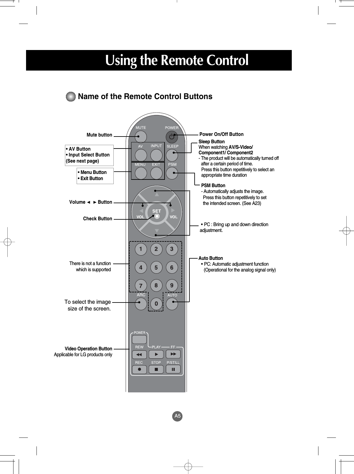
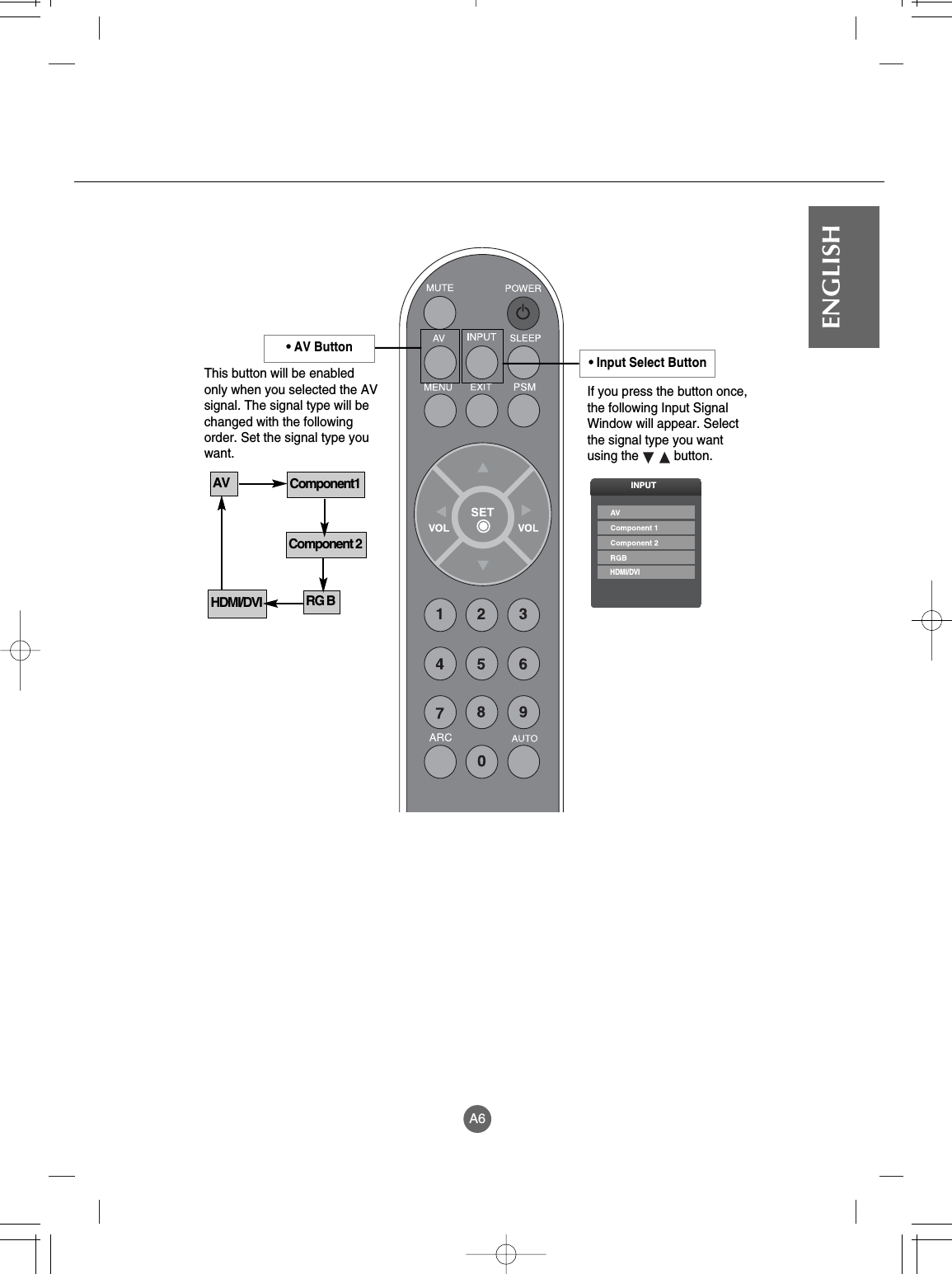
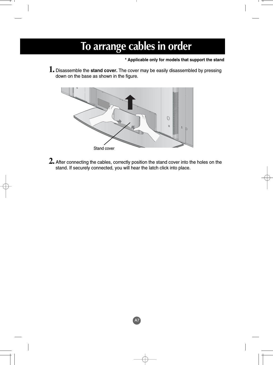
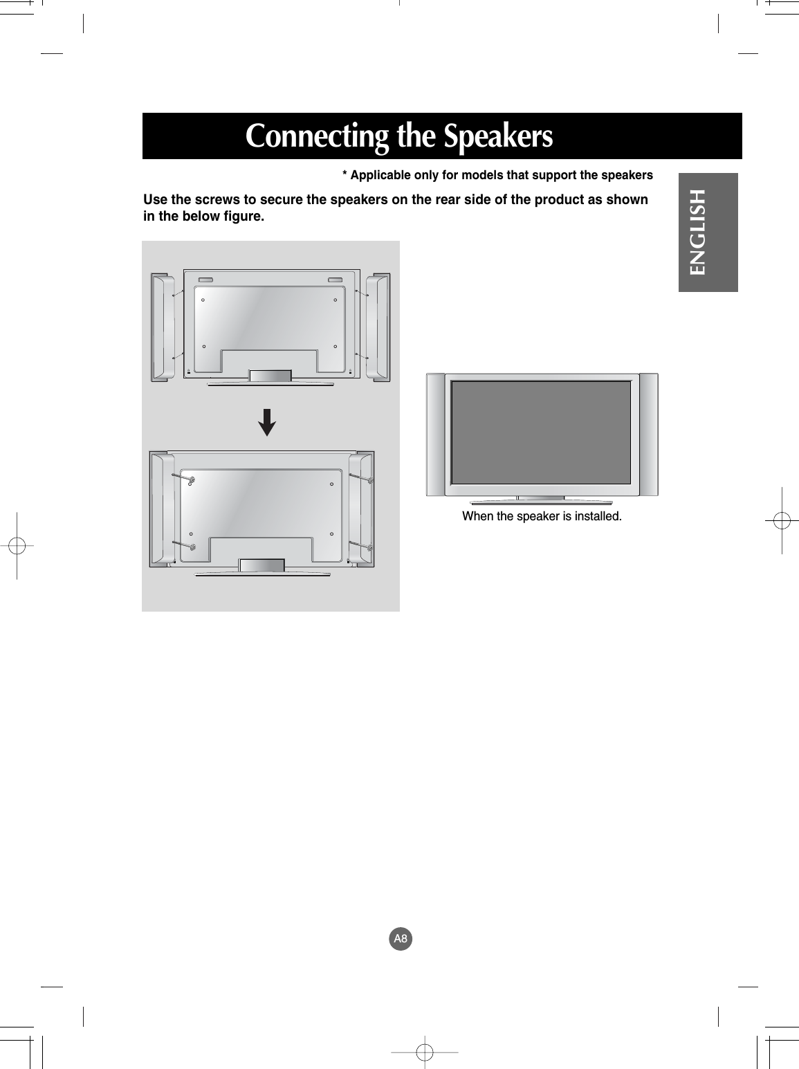
LG Electronics USA M4201CE 42" LCD Monitor User Manual EMISSION TEST REPORT
LG Electronics USA 42" LCD Monitor EMISSION TEST REPORT
UserManual.wiki
>
LG Electronics USA
>
M4201CE User Manual
USERS MANUAL
Navigation menu
Upload a User Manual
Namespaces
Wiki Guide
HTML
PDF
Info
Views
User Manual
Discussion / Help
Navigation

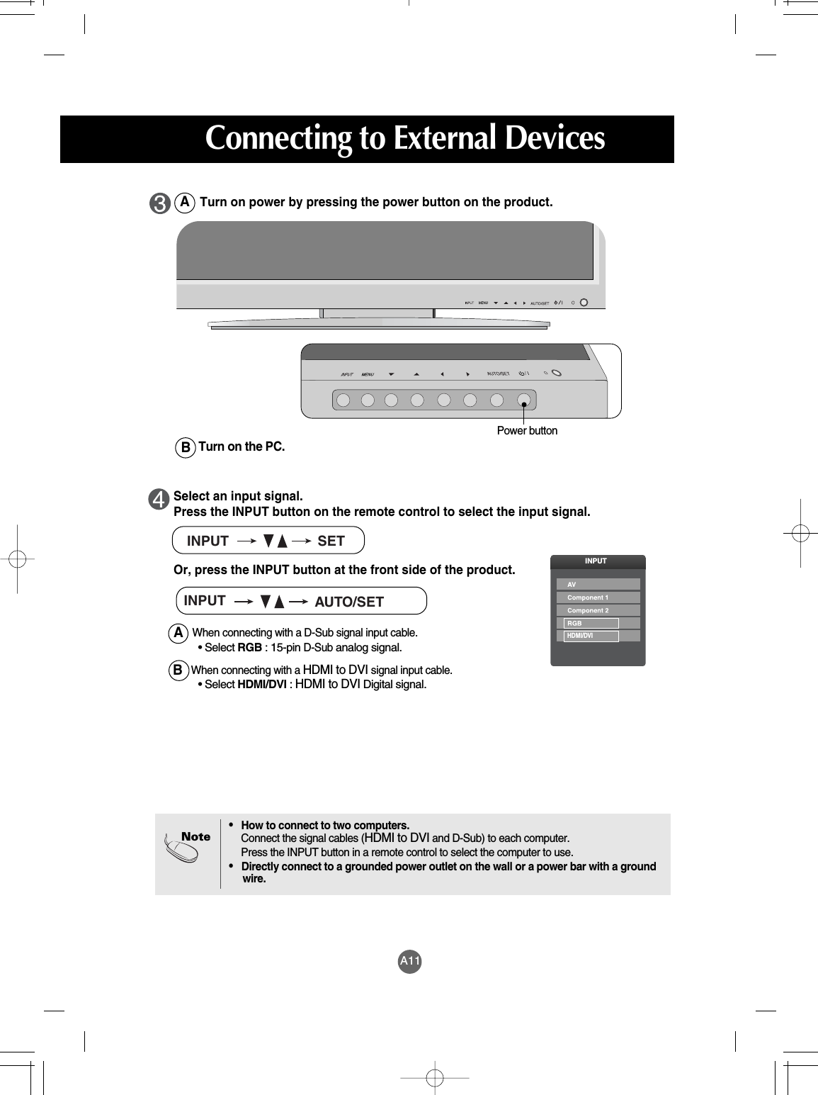
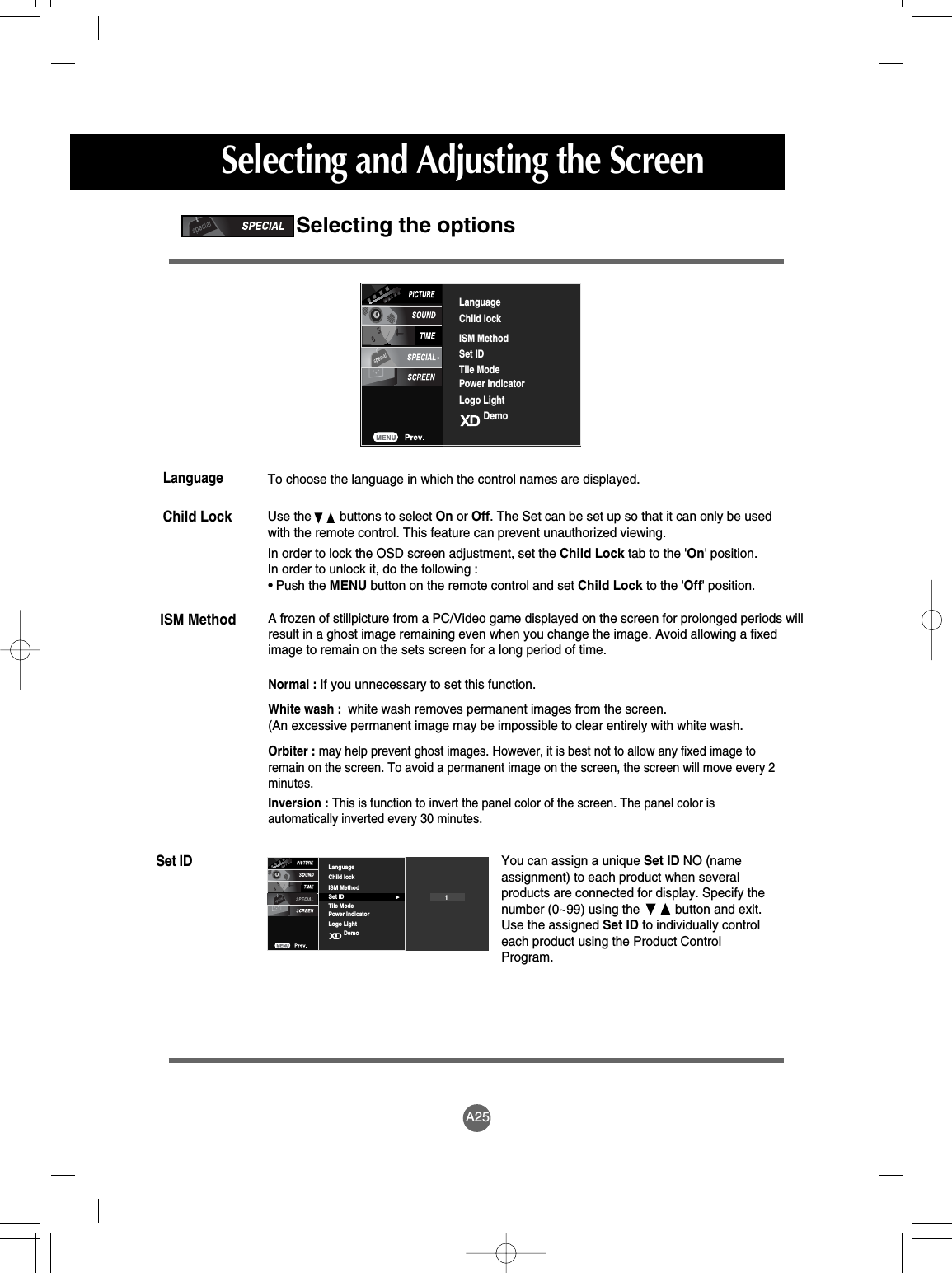
![A18ENGLISH• The unit that receives the signal from the remote control.Name of the Buttons in the Screen Adjustment Unit[For PC Analog signal][Other signals]• The current signal and mode information will be displayed.AUTO/SELECT ButtonAV Composite VideoComponent 1 HDTV, DVDComponent 2 HDTV, DVDRGB 15-pin D-Sub analog signalHDMI/DVI Digital signal• Select the input signal INPUT ButtonINPUTHDMI/DVIINPUT AUTO/SETIR Receiver Button](https://usermanual.wiki/LG-Electronics-USA/M4201CE/User-Guide-641819-Page-13.png)
![A34ENGLISHNOTEInformation in this document is subject to change without notice.[32 inch] 32 inches (80.04 cm) TFT (Thin Film Transistor) LCD (Liquid Crystal Display) PanelVisible diagonal size: 80.04 cm0.5025 mm (Pixel Pitch)[37 inch] 37 inches (94.03 cm) TFT (Thin Film Transistor) LCD (Liquid Crystal Display) PanelVisible diagonal size: 94.03 cm0.6000 mm (Pixel Pitch)[42 inch] 42 inches (106.73 cm) TFT (Thin Film Transistor) LCD (Liquid Crystal Display) PanelAnti-Glare coatingVisible diagonal size: 106.73 cm0.681 mm (Pixel Pitch)[32 inch]Rated Voltage AC 100-240V~ 50/60Hz 1.5APower Consumption On Mode : 145WSleep Mode : ≤1W (RGB) / 4W (HDMI, DVI)Off Mode : ≤1W[37 inch]Rated Voltage AC 100-240V~ 50/60Hz 2.0APower Consumption On Mode : 180WSleep Mode : ≤1W (RGB) / 4W(HDMI, DVI)Off Mode : ≤1W[42 inch]Rated Voltage AC 100-240V~ 50/60Hz 2.5APower Consumption On Mode : 240WSleep Mode : ≤1W (RGB) / 4W(HDMI, DVI)Off Mode : ≤1WThe product specifications can change without prior notice for product improvement.LCD PanelPowerSpecifications](https://usermanual.wiki/LG-Electronics-USA/M4201CE/User-Guide-641819-Page-25.png)
![A35SpecificationsWidth x Height x Depth[32 inch][1] 80.30 cm (31.61 inches) x 54.00cm (21.26 inches) x 18.00 cm (7.09 inches)[2] 80.30 cm (31.61 inches) x 49.30 cm (19.4 inches) x 9.99 cm (3.93 inches)[3] 96.40 cm (37.95 inches) x 54.00cm (21.26 inches) x 18.00 cm (7.09 inches)[4] 96.40 cm (37.95 inches) x 49.30 cm (19.4 inches) x 9.99 cm (3.93 inches)[37 inch][1] 92.80 cm (36.54 inches) x 61.90 cm (24.37 inches) x 22.77 cm (8.96 inches)[2] 92.80 cm (36.54 inches) x 57.12 cm (22.49 inches) x 11.50 cm (4.53 inches)[3] 112.9 cm (44.45 inches) x 61.90 cm (24.37 inches) x 22.77 cm (8.96 inches)[4] 112.9 cm (44.45 inches) x 57.12 cm (22.49 inches) x 11.50 cm (4.53 inches)[42 inch][1] 105.7 cm (41.61 inches) x 70.20 cm (27.64 inches) x 29.45 cm (11.59 inches)[2] 105.7 cm (41.61 inches) x 65.30 cm (25.71 inches) x 11.91 cm (4.69 inches)[3] 125.9 cm (49.57 inches) x 70.20 cm (27.64 inches) x 29.45 cm (11.59 inches)[4] 125.9 cm (49.57 inches) x 65.30 cm (25.71 inches) x 11.91 cm (4.69 inches)Dimensions&Weight[1]WH[2]WH[3]WHDDDD[4]WHThe product specifications can change without prior notice for product improvement.](https://usermanual.wiki/LG-Electronics-USA/M4201CE/User-Guide-641819-Page-26.png)
![A36ENGLISHDimensions&WeightNet[32 inch][1] 19.4 kg (42.77 lbs) [2] 16.0 kg (35.27 lbs)[3] 21.1 kg (46.52 lbs) [4] 17.7 kg (39.02 lbs)[37 inch][1] 26.1 kg (57.54 lbs) [2] 22.0kg (48.50 lbs)[3] 30.5 kg (67.24 lbs) [4] 25.7 kg (56.66 lbs)[42 inch][1] 35.2 kg (77.60 lbs) [2] 30.8 kg (67.90 lbs)[3] 38.0 kg (83.77 lbs) [4] 33.6 kg (74.07 lbs)The product specifications can change without prior notice for product improvement.](https://usermanual.wiki/LG-Electronics-USA/M4201CE/User-Guide-641819-Page-27.png)