LG Electronics USA MR50001WFUS WLAN UNIT User Manual
LG Electronics USA WLAN UNIT Users Manual
Users Manual
LGE Internal Use Only
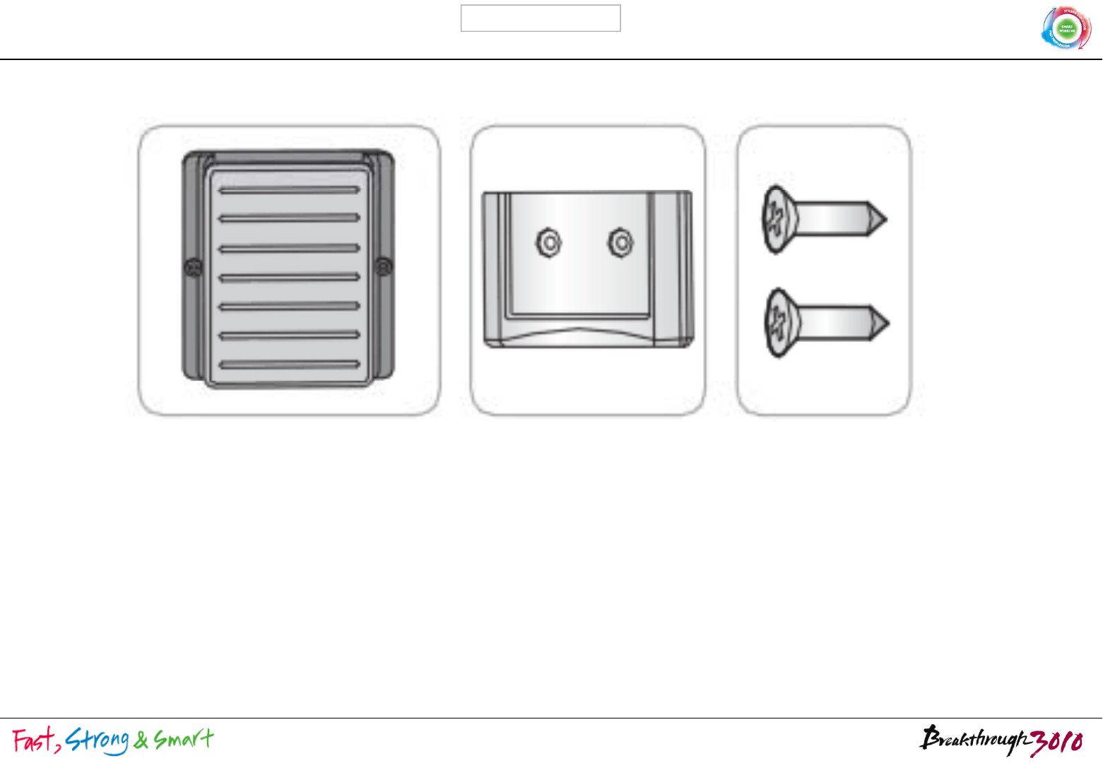
WLAN UNIT & Accessories
WLAN UNIT WLAN UNIT Holder Screw(2ea)
1 / 8
LGE Internal Use Only
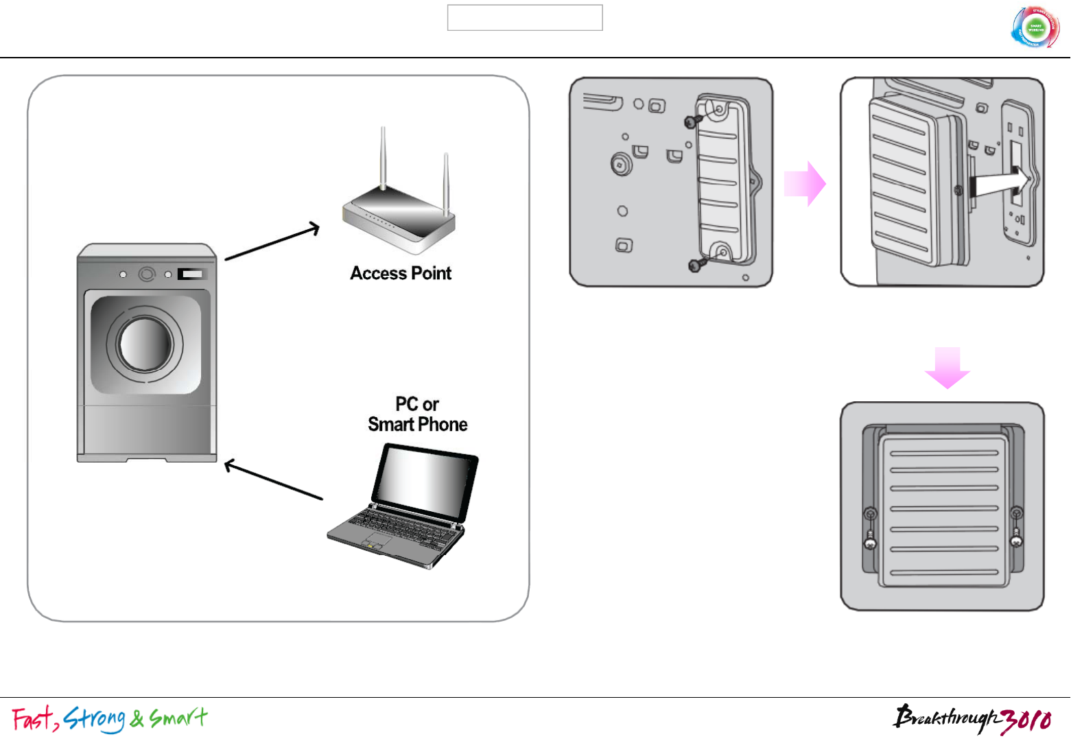
WLAN UNIT setting(Connection)
Smart Washing Machine WLAN UNIT connected to
Washing Machine
※ To ensure com
p
liance with FCC RF ex
p
osure re
q
uirements, this
2 / 8
ppq
device must be installed in a location where the antenna of the device
will have a minimum distance of at least 10 cm
LGE Internal Use Only
4. Set the requirement of Wi-Fi Modem which is on the product
ih hi h
dSi d
bl
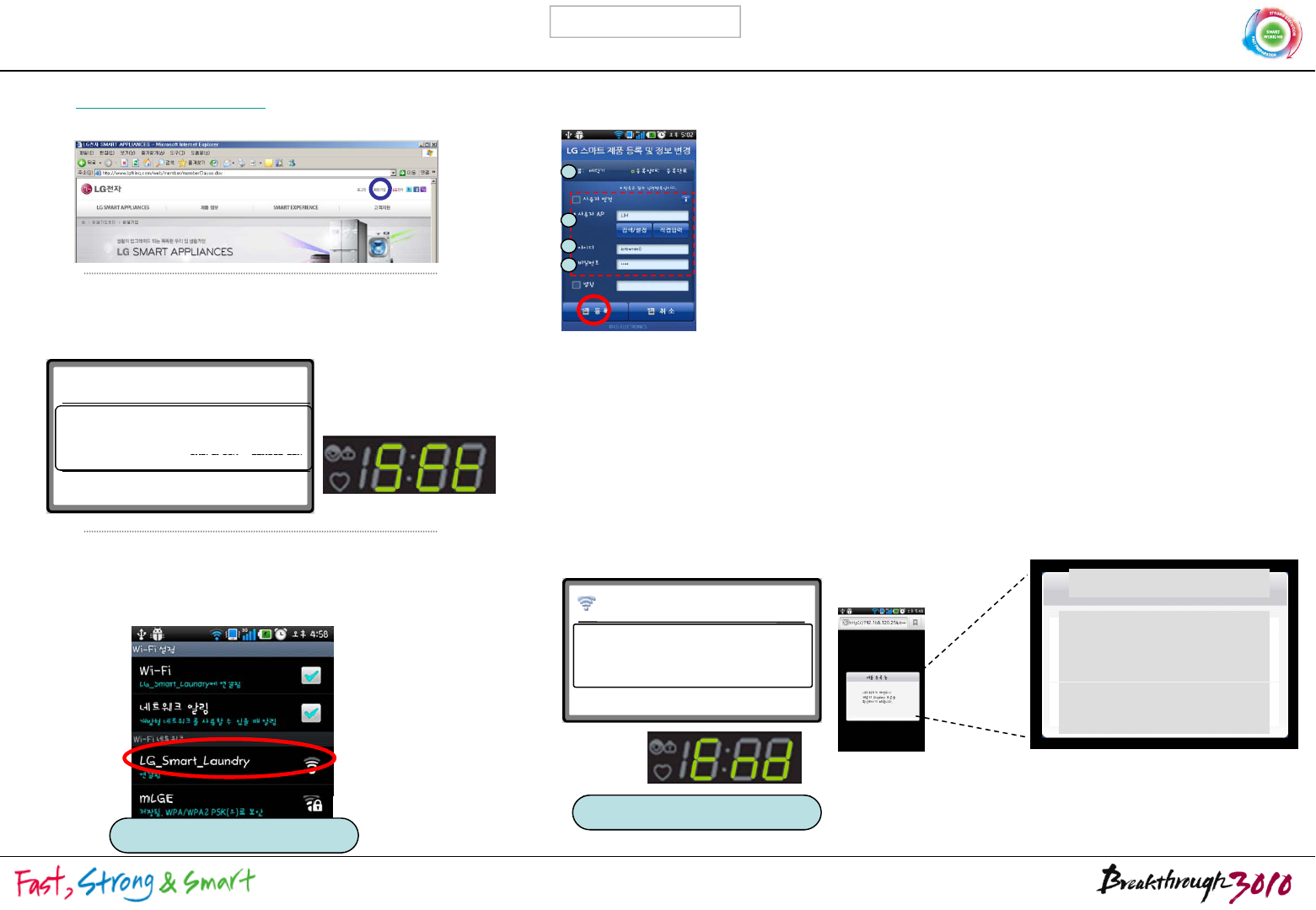
1. Access LG Smart Server Homepage with computer
(http://www.smartthinQ.com) and register ID and
d
WLAN UNIT setting(Smart Phone )
w
i
t
h
pus
hi
ng t
h
e”Pro
d
uct
S
ett
i
ng Mo
d
e”
b
e
l
ow.
passwor
d
.
2
1
2. Apply purchased WLAN UNIT to Smart Washing
Machine, push the reservation button for more than
3 sec. after turning on the washing machine.
shows
‘
Wi
-
Fi Setting mode with
“
Ting
”
sound.
2
3
4
① Check the product is ‘Washing Machine’
② Choose Wireless router(AP) that is currently being used for
User AP
(Input the password and connect if Wireless router(AP) has
security application.)
③ ID/PW : mandator
y
information
제품이 등록되지 않았습니다.
제품 등록 방법은
제품 등록하는 방법 버튼을 눌러
확인할
수
있습니다
.
shows
Wi
Fi
Setting
mode
with
Ting
sound.
Wi-Fi Setting Mode
Access Wi-Fi Modem setting mode
with Smart Phone or Laptop.
or
y
(ID/PW of LG Smart Server registration)
* Name : In case of using several product, Give name to
distinguish easily(Optional)
④ Check the registered information and click the Register
Button to complete the registration. Smart phone and
Product show the completion message as below.
확인할
수
있습니다
.
3. Touch the ‘Wi-Fi set’button below and choose
‘LG_Smart_Laundry’ among Wi-Fi Network. When state
h“C td” bkt ti ith
IP : 192.168.120.254
SSID : LG_Smart_Laundry
Wi-Fi Setting Mode
Wi-Fi Setting has
completed.
네트워크는 차단되니
제품 등록 완료는
제품
표시부를
s
h
ows
“C
onnec
t
e
d”
, come
b
ac
k
t
o curren
t
i
mage w
ith
using back button of smart phone. Product registering
Network will be
disconnected,
Check the product
제품
표시부를
확인하시기 바랍니다.
Check
the
product
showing part for register
completion.
or
<Product showing part> <Smart Phone image>
Product Setting Mode
Wi-Fi Set
3 / 8
WLAN UNIT Setting (Product)
<Wi-Fi Settin
g
for Product
(
Refer the bottom
)
>
g( )
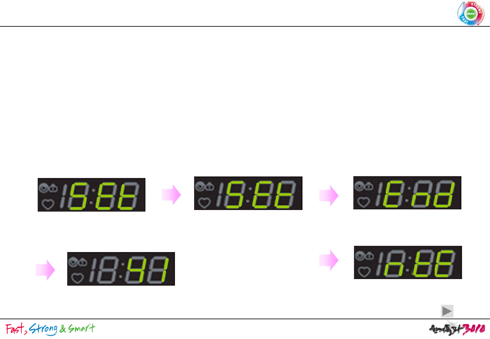
<WLAN UNIT Setting and Reception check>
18:88 shows Error type when it is failed, or Set mode entering has canceled without any setting (Cancel in Web or App)
•User contacts the Setup mode and save the SSID/Password and user’s information for product registration.
•Enter Wi-Fi Setting Mode after pushing Time Delay or Delay Wash (W) / Time Dry for 3 sec.
• Pushing Long Key(product button is not operating at this condition) shows Wi-Fi condition(L0(Unconnected),
L1 L2 L3(connection intensity) displayed on 18:88)
If WLAN UNIT is not installed nothing is on the 18:88 while the operation
<WLAN
UNIT
Setting
and
Reception
check>
L1
,
L2
,
L3(connection
intensity)
displayed
on
18:88)
.
If
WLAN
UNIT
is
not
installed
,
nothing
is
on
the
18:88
while
the
operation
.
Wi
-
Fi Setting Mode
Wi
Fi Setting Mode
Wi
Fi Setting Mode
Wi
-
Fi
Setting
Mode
Wi-Fi 설정 중..
Wi
-
Fi
Setting
Mode
Wi
-
Fi
Setting
Mode
Connection with smart phone or lab top
From exterior
Entering User’s information
:SSID/Password
LED shows End on 18:88
Changed to stand by mode automatically.
Set on 18:88 Set on 18:88
-Using mode is changed when Setting is completed.
LED shows ntE (network Error, Fail) mode on
18:88. changed to stand by mode automatically.l
3 sec. later
Entering failure
Same as power on condition.
Victor Panel
4 / 8
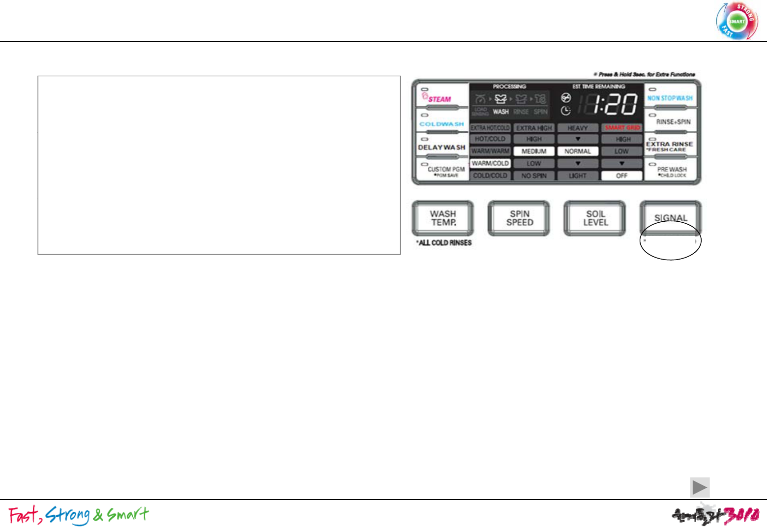
Smart Grid Function Application
<Function Definition>
Smart on
- electric product is operating with DR Signal from electric
Power company(Hyb, Cloud included).
-
Follow AHAM standard
Follow
AHAM
standard
.
- DR Signal Acceptable with Smart On button activated and
Modem is in.
- When DR signal is in, receive DL/SR separately(Duration
time >10 : DL else SR) with this signal product is operating
Smart on
time
>10
:
DL
else
SR)
,
with
this
signal
product
is
operating
Delay Start and Energy Save motion by itself. But for this
product, do not guide to customers
1. Place Smart on(provisional)button (Long Key(more than 3 sec.) of Signal button) and Smart on
LED on the product Panel.
2. Check Modem is in, push the smart button, then Smart On LED turns on.If Modem is not in, Smart
On LED never turns on when
p
ushin
g
Smart On Button.
pg
3. Inner Algorithm(Smart Grid related signal processing, AHAM based) is same as Rocky2 TFT LCD
standard.
4. Modem Reset function is needed and can be defined as below.
With Power On, Operate with Wi-Fi Setting Key + pushing signal for more than 6 sec.
rSt(reset) on 18:88 and blink, show End when completed.
If rSt and End is within 1~2 sec., rSt blinks when Reset has done normally.
After completion, it doesn’t go off before customer sets “power off”. When this status continues for
4 min., it goes off automatically like product’s basic operation.
f
I
f
Wi-Fi Modem is not in, it may not enter to Modem Reset Mode.
Victor Panel
5 / 8

Smart Diagnosis
Final saved Diagnosis factor sends to server when pushing the Smart Diagnosis button(Washing
Final
saved
Diagnosis
factor
sends
to
server
when
pushing
the
Smart
Diagnosis
button(Washing
machine: water temp. dryer: temp.)
In case of Audible, information of 1 cycle only will be sent because of time restraint(sending takes
about 15 sec.)
Wi
-
Fi also send the final saved diagnosis factor to server
Wi
-
Fi
also
send
the
final
saved
diagnosis
factor
to
server
.
Function Definition by detailed using Scene will be identified after additional consulting.
Application will be also identified after additional consulting.
Wi
-
Fi also can check
Wi
-
Fi
also
can
check
.
6 / 8
<Function Definition>
Smart Access
<Function
Definition>
: Access and Adapt is available after WLAN UNIT Setting completion.
In case of going out or getting to work after operating Washing Machine,
Smart Phone can power off or monitor washing machine.
1. Smart Remote Control Function Definition
1-1. Power On/Off Function Definition
1
1
1
Power
On : Power can not be On under any circumstance from exterior
< Function Application >
1
-
1
-
1
.
Power
On
:
Power
can
not
be
On
under
any
circumstance
from
exterior
.
1-1-2. Power Off : Power off possible in case of machine on, reservation set & cycle
operated.
1-2-3. Notice Service
After starting cycles notice the progress of washing cycle through Push message
After
starting
cycles
,
notice
the
progress
of
washing
cycle
through
Push
message
,
and send washing completion message when cycle starts and ends.
2. Smart Remote Control Monitoring Function : washing machine’s real time operating progress
can be checked from exterior
can
be
checked
from
exterior
7 / 8
FCC Notice
THIS DEVICE COMPLIES WITH PART 15 OF THE FCC RULES
THIS
DEVICE
COMPLIES
WITH
PART
15
OF
THE
FCC
RULES
.
OPERATION IS SUBJECT TO THE FOLLOWING TWO CONDITIONS:
(1) THIS DEVICE MAY NOT CAUSE HARMFUL INTERFERENCE, AND
(2) THIS DEVICE MUST ACCEPT ANY INTERFERENCE RECEIVED,
INCLUDING INTERFERENCE THAT MAY CAUSE UNDERSIRED OPERATION.
This equipment has been tested and found to comply with the limits for a Class B digital device, pursuant
to part 15 of the FCC Rules These limits are designed to provide reasonable protection against harmful
to
part
15
of
the
FCC
Rules
.
These
limits
are
designed
to
provide
reasonable
protection
against
harmful
interference in a residential installation. This equipment generates, uses and can radiate radio frequency
energy and, if not installed and used in accordance with the instructions, may cause harmful interference to
radio Communication. However, there is no guarantee that interference will not occur in a particular installation.
If this equipment does cause harmful interference to radio or television reception which can be determined by
If
this
equipment
does
cause
harmful
interference
to
radio
or
television
reception
,
which
can
be
determined
by
turning the equipment off and on, the user is encouraged to try to correct the interference by one or more of
the following measures :
Reorient or relocate the receiving antenna
-
Reorient
or
relocate
the
receiving
antenna
.
- Increase the separation between the equipment and receiver.
- Connect the equipment into an outlet on a oircuit difference from
that to which the receiver is connected.
Consult the dealer of an experienced radio/TV technician for help
-
Consult
the
dealer
of
an
experienced
radio/TV
technician
for
help
.
NOTE : The manufacturer is not responsible for any radio or TV interference caused by unauthorized
modifications to this equipment. Such modifications could void the user's authority to operate the equipment.
8 / 8