LG Electronics USA MU60PZ10 60 Inch Plasma Display User Manual Users manual
LG Electronics USA 60 Inch Plasma Display Users manual
Users manual

PLASMA DISPLAY PANEL
ON/OFF INPUT SELECT VOLUME
P/NO : 3828VA0277B
(NP00KA)
PLASMA DISPLAY PANEL
Please read this owner’s manual carefully before
operating the Monitor.
Retain it for future reference.
Record model number and serial number of the
Monitor.
See the label attached on the back of the Monitor
and quote this information to your dealer when you
require service.
Model number : DPDP60W
Serial number : DPDP60W
OWNER’S MANUAL
ON/OFF INPUT SELECT VOLUME
FCC NOTICE
•DPDP60W : A Class B digital device
This equipment has been tested and found to comply with the limits for a Class B digital device, pursuant
to Part 15 of the FCC Rules. These limits are designed to provide reasonable protection against harmful
interference in a residential installation. This equipment generates, uses and can radiate radio frequency
energy and, if not installed and used in accordance with the instructions, may cause harmful interference
to raido communications. However, there is no guarantee that interference will not occur in a particular
installation. If this equipment does cause harmful interference to radio or television reception, which can
be determined by turning the equipment off and on, the user is encouraged to try to correct the interfer-
ence by one or more of the following measures:
- Reorient or relocate the receiving antenna.
- Increase the separation between the equipment and receiver.
- Connect the equipment into an outlet on a circuit different from that to which the receiver is connected.
- Consult the dealer or an experienced radio/TV technician for help.
WARNING
This is Class B product. In a domestic environment this product may cause radio interference
in which case the user may be required to take adequate measures.
WARNING
TO REDUCE THE RISK OF FIRE AND ELECTRIC SHOCK, DO NOT EXPOSE THIS PROD-
UCT TO RAIN OR MOISTURE.

Keep this manual
with Monitor for
future easy refer-
ence)
Table of Contents
First step
WARNINGS ..............................................................4
SAFETY INSTRUCTIONS........................................5
Composition
Front Panel Controls ................................................8
Connection Panel Overview .....................................9
Remote Control Key Functions/Accessories..........10
Installation of the monitor .......................................12
Connection
VCR Setup..............................................................14
Cable TV Setup ......................................................15
External AV Source Setup......................................16
DVD Setup..............................................................17
DTV Setup..............................................................18
PC Setup ................................................................19
PC Computer Mode Feature Check.......................21
PC Computer Mode Adjustments...........................22
PIP function ............................................................25
Twin picture function...............................................28
Using the remote control ........................................30
Basic function
Turning on the Monitor ...........................................31
Selecting language for the menus..........................32
Checking features...................................................33
Time setting
Setting sleep time...................................................34
Picture & Sound
Auto picture control ................................................35
Adjusting picture appearance.................................36
DRP (Digital Reality Picture) ..................................37
Selecting screen item .............................................38
Adjusting sound appearance..................................39
Auto sound control .................................................40
AVL (Auto volume leveler)......................................41
Special function
Using Still function..................................................42
Adjusting OSD Transparency .................................43
Setting picture format .............................................44
Others
Maintenance ...........................................................45
Troubleshooting check list......................................46
Product specifications.............................................47
4
WARNINGS
WARNING:
TO REDUCE THE RISK OF ELECTRIC SHOCK DO NOT REMOVE COVER
(OR BACK). NO USER SERVICEABLE PARTS INSIDE.
REFER TO QUALIFIED SERVICE PERSONNEL.
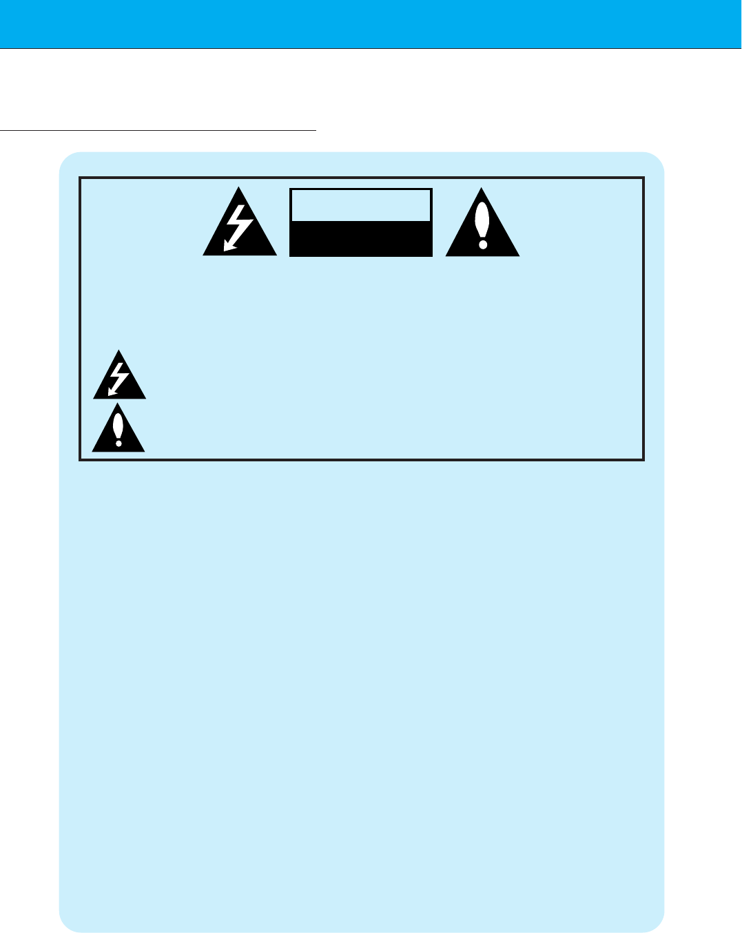
The lightning flash with arrowhead symbol, within an equilateral triangle, is
intended to alert the user to the presence of uninsulated “dangerous voltage”
within the product’s enclosure that may be of sufficient magnitude to consti-
tute a risk of electric shock to persons.
The exclamation point within an equilateral triangle is intended to alert the
user to the presence of important operating and maintenance (servicing)
instructions in the literature accompanying the appliance.
WARNING:
TO PREVENT FIRE OR SHOCK HAZARDS, DO NOT EXPOSE THIS PRODUCT TO
RAIN OR MOISTURE.
CAUTION:
TO PREVENT ELECTRIC SHOCK, MATCH WIDE BLADE OF PLUG TO WIDE SLOT,
FULLY INSERT.
CAUTION:
Do not attempt to modify this product in any way without written authorization from Zenith Electronics
Corporation. Unauthorized modification could void the user’s authority to operate this product.
The responsible party for this device compliance is:
Zenith Electronics Corporation
201 James Record Road
Huntsville, AL 35824, USA
1-877-993-6484
WARNING
RISK OF ELECTRIC SHOCK
DO NOT OPEN
5
First step Composition Connection Basic function Time setting Picture & Sound Special function Others
Important safeguards for you and your new product
Your product has been manufactured and tested with your safety in mind. However, improper
use can result in potential electrical shock or fire hazards. To avoid defeating the safeguards
that have been built into your new product, please read and observe the following safety
points when installing and using your new product, and save them for future reference.
Observing the simple precautions discussed in this booklet can help you get many years of
enjoyment and safe operation that are built into your new product.
This product complies with all applicable U.S. Federal safety requirements, and those of the
Canadian Standards Association.
1. Read Instructions
All the safety and operating instructions
should be read before the product is operat-
ed.
2. Follow Instructions
All operating and use instructions should be
followed.
3. Retain Instructions
The safety and operating instructions should
be retained for future reference.
4. Heed Warnings
All warnings on the product and in the oper-
ating instructions should be adhered to.
5. Cleaning
Unplug this product from the wall outlet
before cleaning. Do not use liquid cleaners
or aerosol cleaners. Use a damp cloth for
cleaning.
6. Water and Moisture
Do not use this product near water, for
example, near a bath tub, wash bowl,
kitchen sink, or laundry tub, in a wet base-
ment, or near a swimming pool.
7. Accessories Carts and Stands
Do not place this product on a slippery or
tilted surface, or on an unstable cart, stand,
tripod, bracket, or table. The product may
slide or fall, causing serious injury to a child
or adult, and serious damage to the product.
Use only with a cart, stand, tripod, bracket,
or table recommended by the manufacturer,
or sold with the product. Any mounting of
the product should follow the manufacturer’s
instructions, and should use a mounting
accessory recommended by the manufac-
turer.
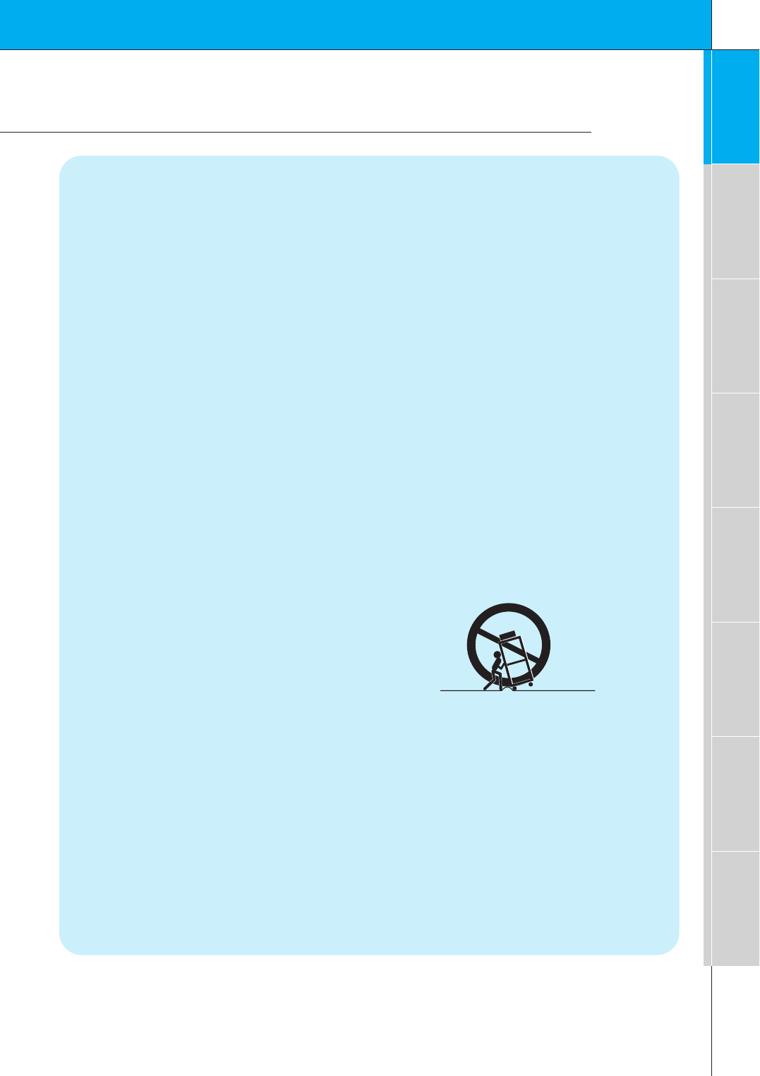
8. Transporting Product
Aproduct and cart combination should be
moved with care. Quick stops, excessive
force, and uneven surfaces may cause the
product and cart combination to overturn.
9. Attachments
Do not use attachments not recommended
by the product manufacturer as they may
cause hazards.
10. Ventilation
Slots and openings in the cabinet are pro-
vided for ventilation and to ensure reliable
operation of the product and to protect it
from overheating, and these openings must
not be blocked or covered.
PORTABLE CART WARNING
(Continued on next page)
SAFETY INSTRUCTIONS
6
SAFETY INSTRUCTIONS
The openings should never be blocked by
placing the product on a bed, sofa, rug, or
other similar surface. This product should
not be placed in a built-in installation such
as a bookcase or rack unless proper ventila-
tion is provided or the manufacturer’s
instructions have been adhered to.
11. Power Sources
This product should be operated only from
the type of power source indicated on the
marking label. If you are not sure of the type
of power supply to your home, consult your
product dealer or local power company. For
products intended to operate from battery
power, or other sources, refer to the operat-
ing instructions.
12. Power-Cord Polarization
This product is equipped with a polarized
alternating-current line plug (a plug having
one blade wider than the other). This plug
will fit into the power outlet only one way.
This is a safety feature. If you are unable to
insert the plug fully into the outlet, try
reversing the plug. If the plug should still fail
to fit, contact your electrician to replace your
obsolete outlet. Do not defeat the safety
purpose of the polarized plug.
13. Power-Cord Protection
Power-supply cords should be routed so
that they are not likely to be walked on or
pinched by items placed upon or against
them, paying particular attention to cords at
plugs, convenience receptacles, and the
point where they exit from the product.
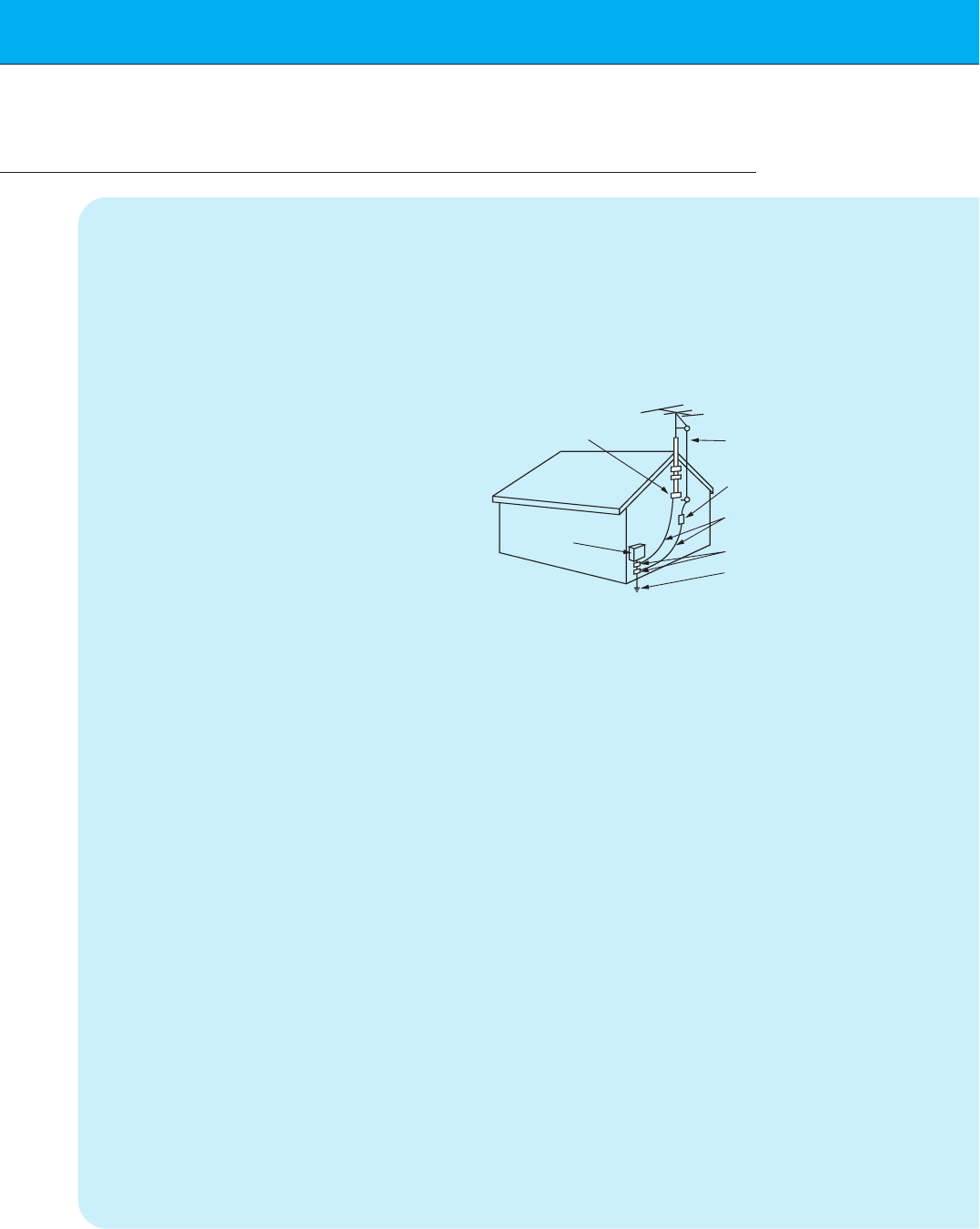
14. Outdoor Antenna Grounding
If an outside antenna or cable system is
connected to the product, be sure the
antenna or cable system is grounded so as
to provide some protection against voltage
surges and built-up static charges. Article
810 of the National Electrical Code (U.S.A.),
ANSI/ NFPA 70 provides information with
regard to proper grounding of the mast and
supporting structure, grounding of the lead-
in wire to an antenna discharge unit, size of
grounding conductors, location of antenna-
discharge unit, connection to grounding
electrodes, and requirements for the
grounding electrode.
15. Lightning
For added protection for this product
(receiver) during a lightning storm, or when
it is left unattended and unused for long
periods of time, unplug it from the wall outlet
and disconnect the antenna or cable sys-
tem. This will prevent damage to the product
due to lightning and power-line surges.
16. Power Lines
An outside antenna system should not be
located in the vicinity of overhead power
lines or other electric light or power circuits,
or where it can fall into such power lines or
circuits. When installing an outside antenna
system, extreme care should be taken to
keep from touching such power lines or cir-
cuits as contact with them might be fatal.
17. Overloading
Do not overload wall outlets and extension
cords as this can result in a risk of fire or
electric shock.
18. Object and Liquid Entry
Never push objects of any kind into this
(Continued from previous page)
Antenna Lead in Wire
Antenna Discharge Unit
(NEC Section 810-20)
Grounding Conductor
(NEC Section 810-21)
Ground Clamps
Power Service Grounding
Electrode System (NEC
Art 250, Part H)
Ground Clamp
Electric Service
Equipment
Example of Grounding According to National
Electrical Code Instructions
NEC - National Electrical Code

7
First step Composition Connection Basic function Time setting Picture & Sound Special function Others
product through openings as they may
touch dangerous voltage points or short-out
parts that could result in a fire or electric
shock. Never spill liquid of any kind on the
product.
19. Servicing
Do not attempt to service this product your-
self as opening or removing covers may
expose you to dangerous voltage or other
hazards. Refer all servicing to qualified ser-
vice personnel.
20. Damage Requiring Service
Unplug this product from the wall outlet and
refer servicing to qualified service personnel
under the following conditions:
a. If the power-supply cord or plug is dam-
aged.
b. If liquid has been spilled, or objects have
fallen into the product.
c. If the product has been exposed to rain
or water.
d. If the product does not operate normally
by following the operating instructions.
Adjust only those controls that are cov-
ered by the operating instructions as an
improper adjustment of other controls
may result in damage and will often
require extensive work by a qualified
technician to restore the product to its
normal operation.
e. If the product has been dropped or the
cabinet has been damaged.
f. If the product exhibits a distinct change
in performance.
21. Replacement Parts
When replacement parts are required, be
sure the service technician has used
replacement parts specified by the manufac-
turer or have the same characteristics as
the original part. Unauthorized substitutions
may result in fire, electric shock, or other
hazards.
22. Safety Check
Upon completion of any service or repairs to
this product, ask the service technician to
perform safety checks to determine that the
product is in proper operating condition.
23. Wall or Ceiling Mounting
The product should be mounted to a wall or
ceiling only as recommended by the manu-
facturer. The product may slide or fall, caus-
ing serious injury to a child or adult, and
serious damage to the product.
24. Heat
The product should be situated away from
heat sources such as radiators, heat regis-
ters, stoves, or other products (including
amplifiers) that produce heat.
8
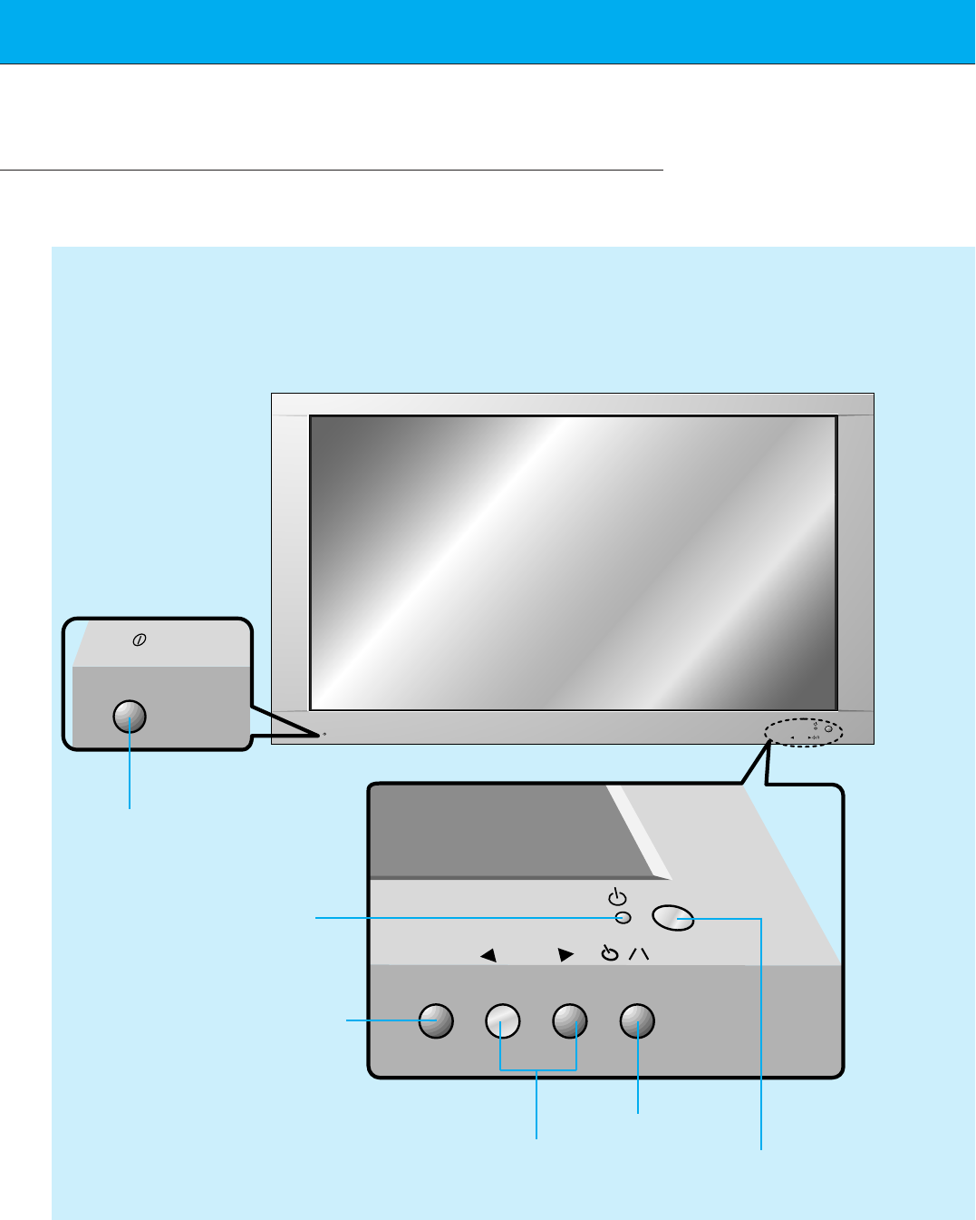
Front Panel Controls
ON/OFF
ON/OFF INPUT SELECT VOLUME
INPUT
SELECT VOLUME
<Front Panel>
Main power button
INPUT SELECT button
Power standby indicator
Illuminates red in standby
Illuminates green when the
Monitor is switched on
Sub power button
VOLUME (FF,GG) buttons Remote control sensor
9
First step Composition Connection Basic function Time setting Picture & Sound Special function Others
(+) ( ) (+)( )
(+) ( ) (+)( )
AUDIO
(MONO)
R L VIDEO Y PB R
P
AV INPUT
AUDIO
R L RL
EXTERNAL SPEAKER (8Ω) AC INPUTAUDIO INPUT S-VIDEO
COMPONENT (480i/480p/720p/1080i) RGB-PC INPUT
(VGA/SVGA/XGA/SXGA)
RGB-DTV INPUT
(480p/720p/1080i)
AUDIO
(MONO)
R L
AV INPUT
COMPONENT (480i/480p/720p/1080i)
(DVD/DTV INPUT)
RGB-PC INPUT
R
AUDIO INPUT
S-VIDEO
EXTERNAL SPEAKER 8Ω
R L
AC INPUT
L
AUDIO
(VGA/SVGA/XGA/SXGA)
RGB-DTV INPUT
(480p/720p/1080i)
VIDEO Y P
B
P
R
(DVD/DTV INPUT)
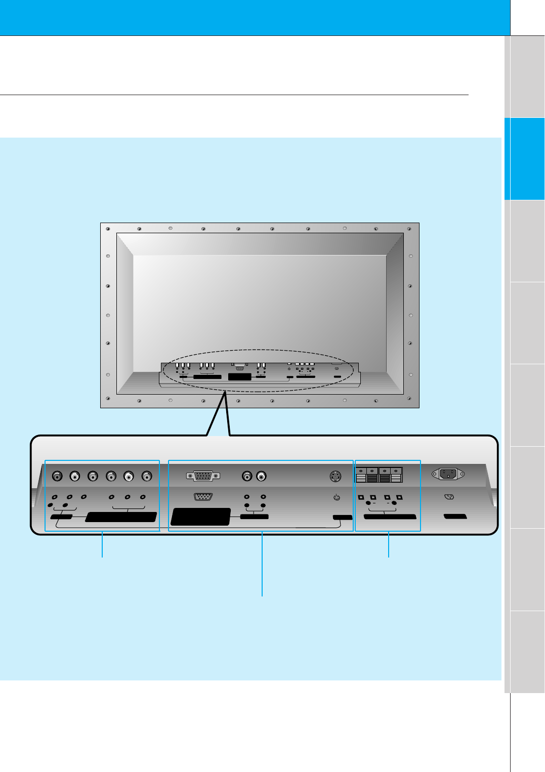
<Back Panel>
AV INPUT /
COMPONENT (480i/480p/720p/1080i)
(DVD/DTV INPUT) sockets
EXTERNAL
SPEAKER (8Ω)
knobs
RGB-PC INPUT (VGA/SVGA/XGA/SXGA)
RGB-DTV INPUT (480p/720p/1080i) /
AUDIO INPUT sockets
Connection Panel Overview
10
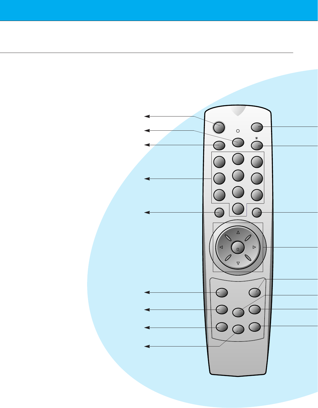
Remote Control Key Functions/Accessories
-When using the remote control aim it at the remote control sensor on the Monitor.
power on
mute
1 3
2
4 6
5
7 9
8
video/pc menu
up
down
vol vol
enter
0
sleep
system off
pip
input select
ratio
twin picture
freeze
easy sound
position
apc
power on button
sleep button
(Refer to p.34)
mute button
switches the sound on or off.
video/pc button
number buttons
pip button
(Refer to p.25)
input select button
(Refer to p.26, 29)
ratio button(Refer to p.44)
When pressing this button,
it’s displayed ARC on screen.
apc button
(Refer to p.35)
11
First step Composition Connection Basic function Time setting Picture & Sound Special function Others
AS mark
Monitor
1.5V
1.5V
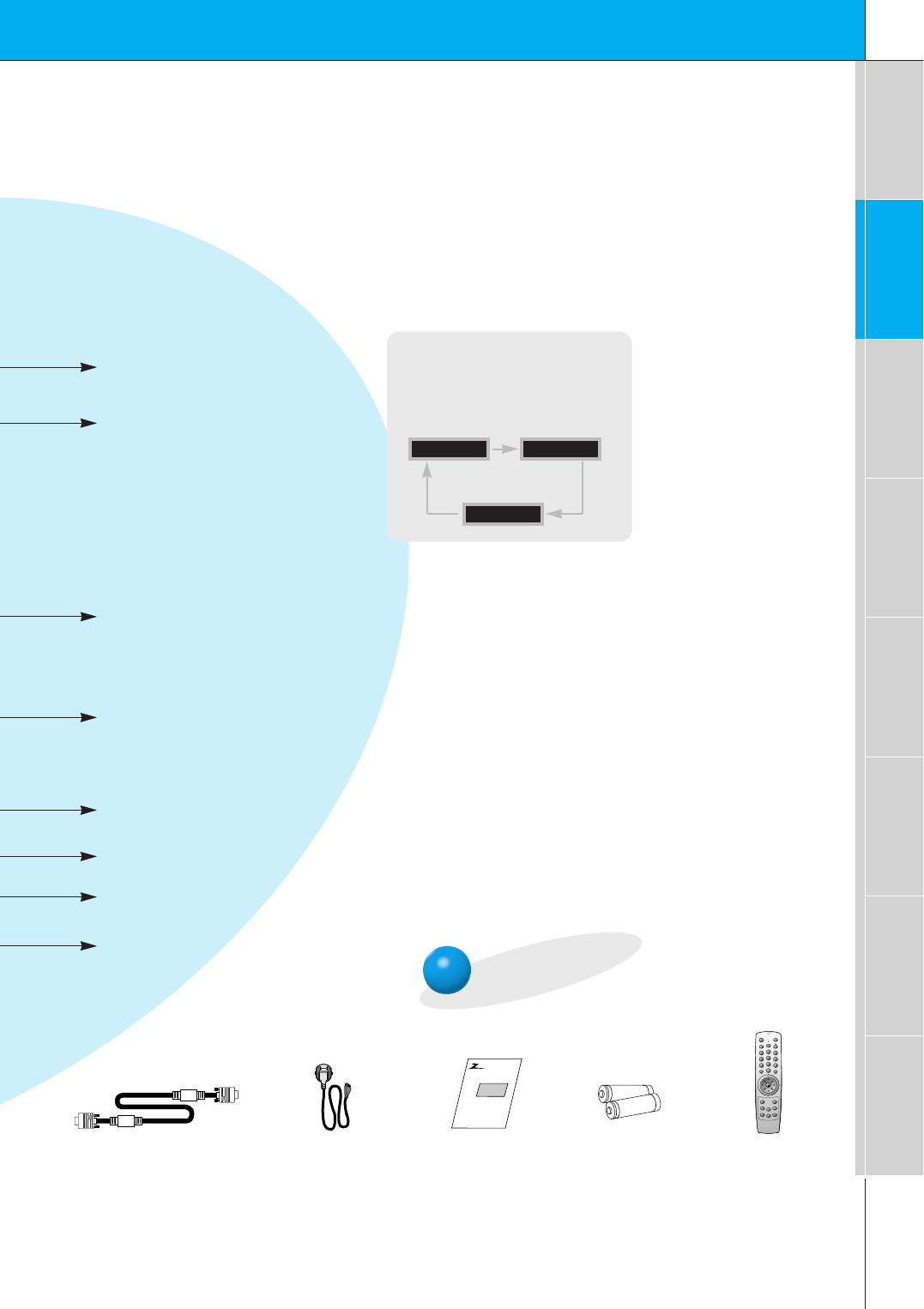
Accessories
D-sub 15 pin cable Power cord
power on
mute
1 3
2
4 6
5
7 9
8
video/pc menu
up
down
vol vol
enter
0
sleep
system off
pip
input select
ratio
twin picture
freeze
easy sound
position
apc
Remote control
Owner’s Manual Alkaline batteries
system off button
menu button
enter button
up/down buttons
vol buttons
twin picture button(Refer to p.28)
When pressing this button,
it’s displayed DW on screen.
freeze button
(Refer to p.42)
position button
(Refer to p.26)
easy sound button(Refer to p.40)
When pressing this button,
it’s displayed DASP on screen.
No function
INPUT SELECT button on the
remote control
Each press of this button changes
the mode as below.
COMPONENT
VIDEO
RGB
12
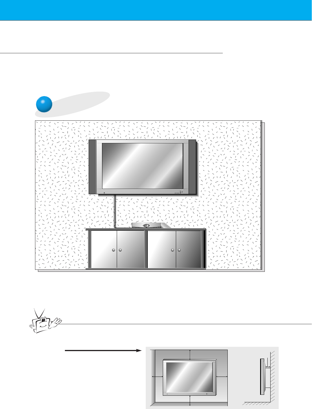
Installation of the Monitor
-Use this product at the place lower than the altitude of 6562 feet (2000m) to get the
best quality of picture and sound.
- Your DPDP60W (Monitor) can be installed on a wall as shown below, or on a desktop
pedestal as shown on the next page.
Wall Mount Installation
•The monitor can be installed on the wall as shown above.
(For further information, refer to the optional ‘(Tilt) wall mounting bracket
Installation and Setup Guide’.)
Tips
• To install this monitor in safety, it must install in a place where is provided a proper
ventilation.
3.94inch
3.94inch
3.94inch3.94inch
1.18inch
a.
(In case of wall mounting type)
13
First step Composition Connection Basic function Time setting Picture & Sound Special function Others
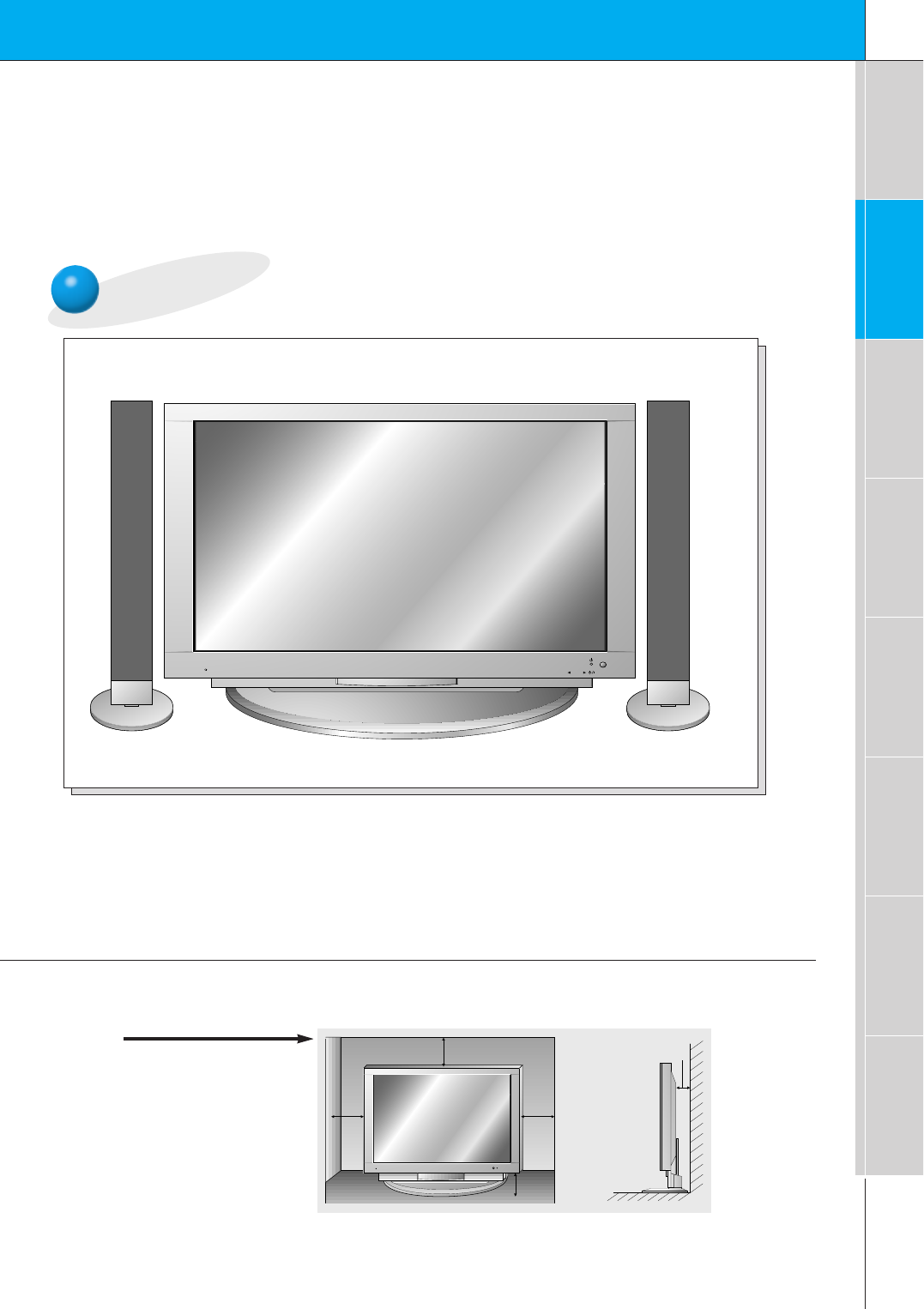
Desktop Pedestal Installation
ON/OFF INPUT SELECT VOLUME
•The Monitor can be installed on the desk as shown above.
(For further information, refer to the optional ‘Desktop stand Installation and Setup Guide’.)
3.94inch
3.94inch
2.36inch
3.94inch
1.18inch
b.
(In case of desktop type)
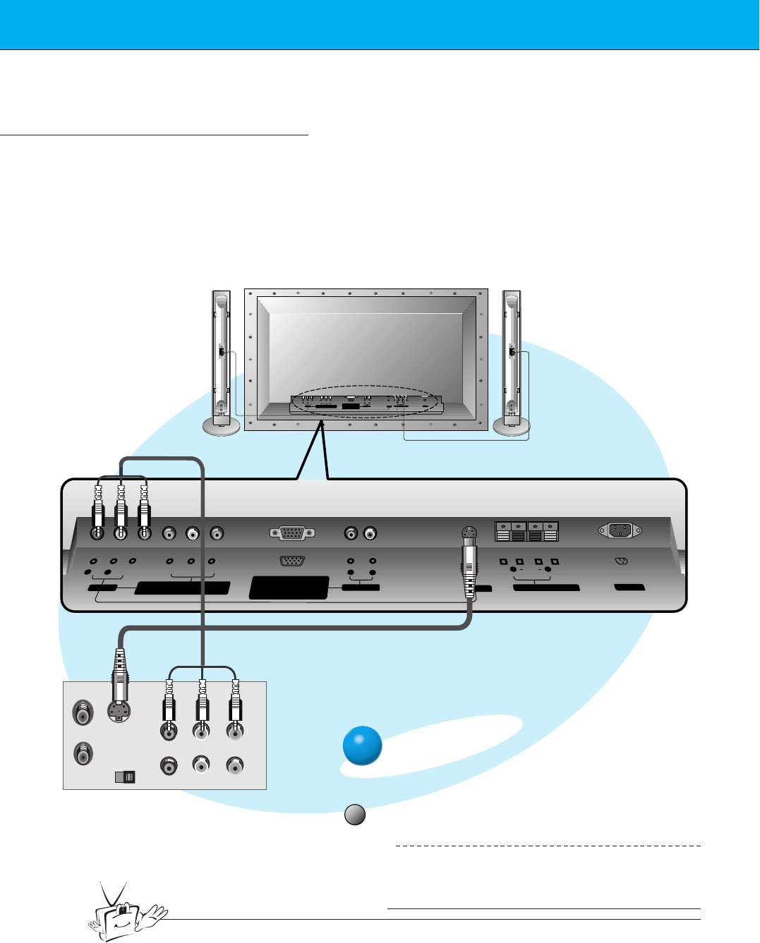
14
VCR Setup
Tips
• To prevent picture noise, keep a appropriate distance between VCR and monitor.
-As shown below, when connecting the Monitor to a VCR, match the colors of AV input
jacks on the Monitor with the output jacks on the VCR: Video = yellow, Audio (Left) =
white, Audio (Right) = red.
- If you have a mono VCR, connect the audio cable from the VCR to the AUDIO(L/MONO)
input of the Plasma Monitor.
- When connecting a S-VIDEO VCR to the S-VIDEO socket, the picture quality will be further
improved.
- If 4:3picture format or still word such as watching VCR or CH label is on the screen for a
long time, that fixed image may remain visible.
S-VIDEO OUT
IN
(R) AUDIO (L) VIDEO
(+) ( ) (+)( )
AUDIO
(MONO)
R L VIDEO Y PB R
P
AV INPUT
AUDIO
R L RL
EXTERNAL SPEAKER (8Ω) AC INPUTAUDIO INPUT S-VIDEO
COMPONENT (480i/480p/720p/1080i) RGB-PC INPUT
(VGA/SVGA/XGA/SXGA)
RGB-DTV INPUT
(480p/720p/1080i)
(DVD/DTV INPUT)
(+) ( ) (+)( )
AUDIO
(MONO)
R L
AV INPUT
COMPONENT (480i/480p/720p/1080i)
(DVD/DTV INPUT)
RGB-PC INPUT
R
AUDIO INPUT
S-VIDEO
EXTERNAL SPEAKER(8Ω)
R L
AC INPUT
L
AUDIO
(VGA/SVGA/XGA/SXGA)
RGB-DTV INPUT
(480p/720p/1080i)
VIDEO Y P
B
P
R
<Back panel of VCR>
<Back panel of the Monitor>
video/pc
To watch VCR
Press video/pc button on the remote con-
trol to select VIDEO.
1
Insert a video tape into the VCR and press
the PLAY button on the VCR.See VCR
owner’s manual.
2
15
First step Composition Connection Basic function Time setting Picture & Sound Special function Others
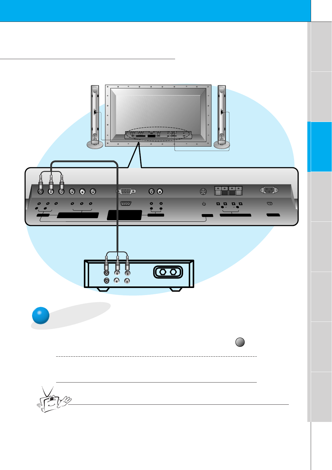
Cable TV Setup
- After subscribing to a cable TV service from a local provider and installing a converter
you can watch cable TV programming.
TV
VCR RF Cable
(R) AUDIO (L) VIDEO
(+) ( ) (+)( )
AUDIO
(MONO)
R L VIDEO Y PB R
P
AV INPUT
AUDIO
R L RL
EXTERNAL SPEAKER (8Ω) AC INPUTAUDIO INPUT S-VIDEO
COMPONENT (480i/480p/720p/1080i) RGB-PC INPUT
(VGA/SVGA/XGA/SXGA)
RGB-DTV INPUT
(480p/720p/1080i)
(DVD/DTV INPUT)
(+) ( ) (+)( )
AUDIO
(MONO)
R L
AV INPUT
COMPONENT (480i/480p/720p/1080i)
(DVD/DTV INPUT)
RGB-PC INPUT
R
AUDIO INPUT
S-VIDEO
EXTERNAL SPEAKER(8Ω)
R L
AC INPUT
L
AUDIO
(VGA/SVGA/XGA/SXGA)
RGB-DTV INPUT
(480p/720p/1080i)
VIDEO Y P
B
P
R
To watch cable TV
Press video/pc button on the remote con-
trol to select VIDEO.
1
Select cable provided channels using the
cable box.
2
video/pc
Tips
•For further information reguarding cable TV, contact the local cable
TV service provider(s).
<Back panel of the Monitor>
<Cable box>
16
R L
AUDIO VIDEO
(+) ( ) (+)( )
AUDIO
(MONO)
R L VIDEO Y PB R
P
AV INPUT
AUDIO
R L RL
EXTERNAL SPEAKER (8Ω) AC INPUTAUDIO INPUT S-VIDEO
COMPONENT (480i/480p/720p/1080i) RGB-PC INPUT
(VGA/SVGA/XGA/SXGA)
RGB-DTV INPUT
(480p/720p/1080i)
(DVD/DTV INPUT)
(+) ( ) (+)( )
AUDIO
(MONO)
R L
AV INPUT
COMPONENT (480i/480p/720p/1080i)
(DVD/DTV INPUT)
RGB-PC INPUT
R
AUDIO INPUT
S-VIDEO
EXTERNAL SPEAKER(8Ω)
R L
AC INPUT
L
AUDIO
(VGA/SVGA/XGA/SXGA)
RGB-DTV INPUT
(480p/720p/1080i)
VIDEO Y P
B
P
R
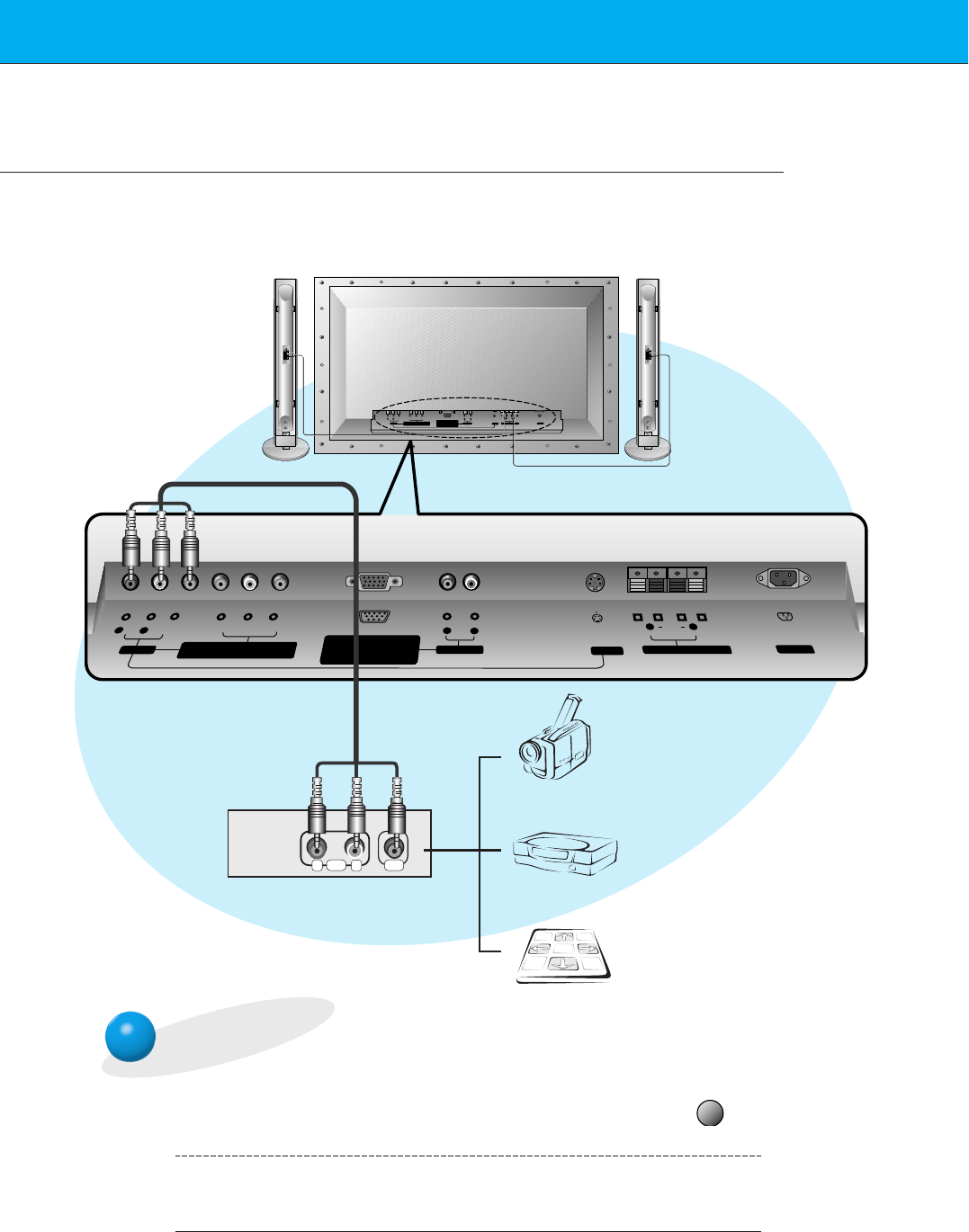
Camcorder
Video game set
DDR
To watch external AV source
Press video/pc button on the remote con-
trol to select VIDEO.
1
Operate the corresponding external equip-
ment. See external equipment operating
guide.
2
video/pc
External AV Source Setup
- As shown below, when connecting the Monitor to an external source, match the colors of AV
input jacks on the Monitor with the output jacks on the audio/video equipment: Video = yel-
low, Audio (Left) = white, Audio (Right) = red.
< Back panel of the Monitor>
17
First step Composition Connection Basic function Time setting Picture & Sound Special function Others
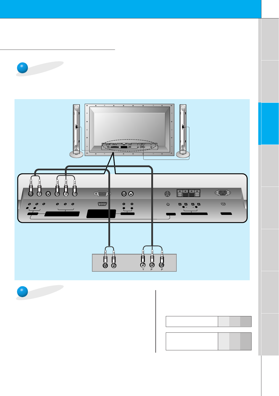
DVD Setup
• Connect DVD video inputs to Y, PB, PRof COMPONENT (480i/480p/720p/1080i)
(DVD/DTV INPUT) and audio inputs to Audio sockets of AV INPUT.
How to connect a DVD (digital video disk player)
How to use
• Turn on the DVD player, and insert a DVD.
• Press video/pc button on the remote control to select
COMPONENT. Use DVD to play DVD, see DVD owner’s
manual.
•Component Input ports
Connect DVD player jacks to Monitor
Component input jacks as indicated below.
(+) ( ) (+)( )
AUDIO
(MONO)
R L VIDEO Y PB R
P
AV INPUT
AUDIO
R L RL
EXTERNAL SPEAKER (8Ω) AC INPUTAUDIO INPUT S-VIDEO
COMPONENT (480i/480p/720p/1080i) RGB-PC INPUT
(VGA/SVGA/XGA/SXGA)
RGB-DTV INPUT
(480p/720p/1080i)
(DVD/DTV INPUT)
(+) ( ) (+)( )
AUDIO
(MONO)
R L
AV INPUT
COMPONENT (480i/480p/720p/1080i)
(DVD/DTV INPUT)
RGB-PC INPUT
R
AUDIO INPUT
S-VIDEO
EXTERNAL SPEAKER(8Ω)
R L
AC INPUT
L
AUDIO
(VGA/SVGA/XGA/SXGA)
RGB-DTV INPUT
(480p/720p/1080i)
VIDEO Y P
B
P
R
BR
(R) AUDIO (L)
< Back panel of a DVD player>
Component ports of the
Monitor YPBPR
Video output ports
of DVD player
Y
Y
Y
Y
Pb
B-Y
Cb
PB
Pr
R-Y
Cr
PR
< Back panel of the Monitor>
18
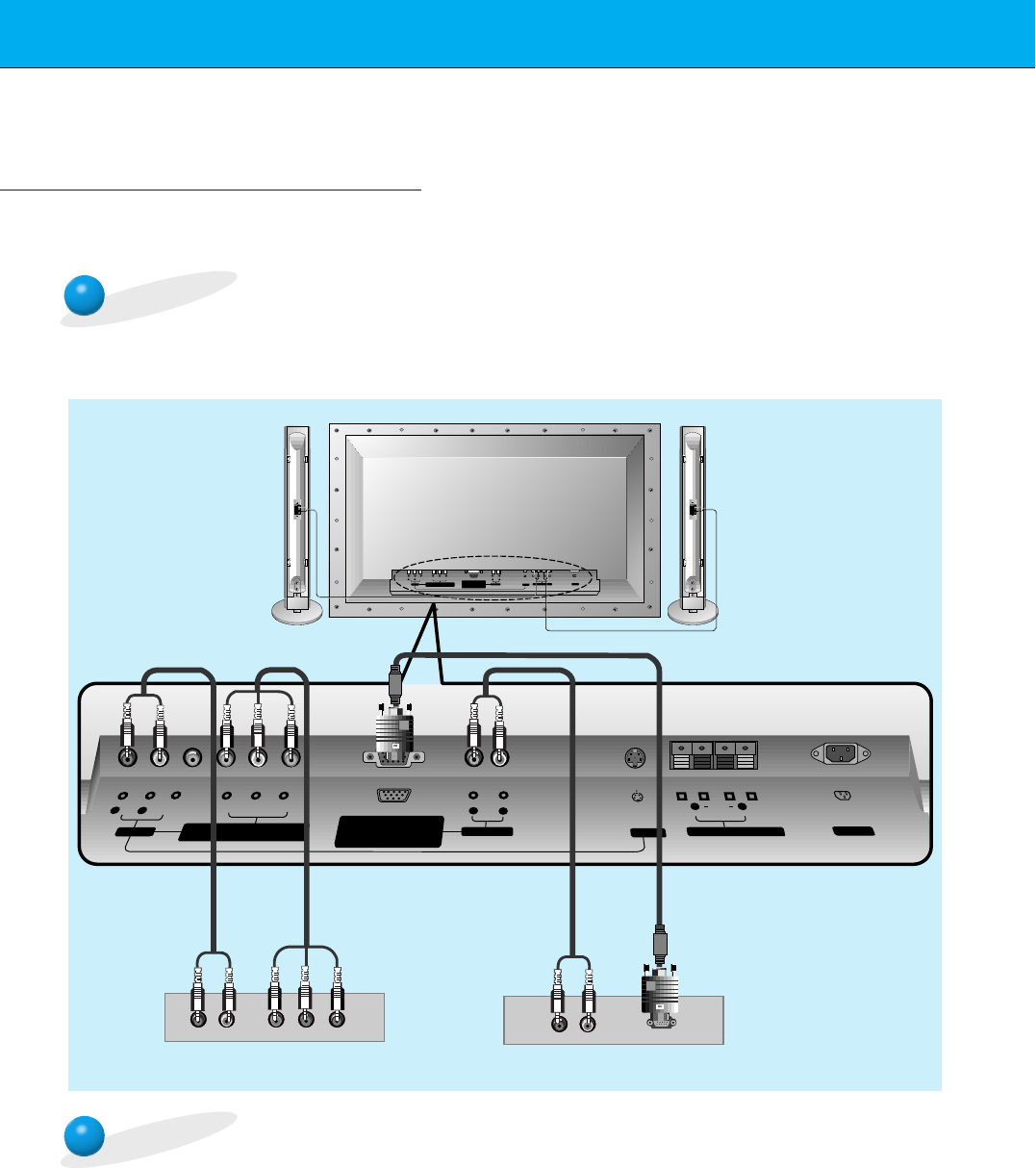
DTV Setup
- To watch digitally broadcast programs, purchase/connect a digital SET-TOP BOX.
- If the DTV signal is input to the Monitor, you can adjust the picture size.
- You can select only the 16:9 picture format in DTV 720p/1080i mode.
How to connect a user-supplied Digital Set-top Box
How to use
(R) AUDIO (L)
(R) AUDIO (L) Y P
B R
PDTV OUTPUT
(+) ( ) (+)( )
AUDIO
(MONO)
R L VIDEO Y PB R
P
AV INPUT
AUDIO
R L RL
EXTERNAL SPEAKER (8Ω) AC INPUTAUDIO INPUT S-VIDEO
COMPONENT (480i/480p/720p/1080i) RGB-PC INPUT
(VGA/SVGA/XGA/SXGA)
RGB-DTV INPUT
(480p/720p/1080i)
(DVD/DTV INPUT)
(+) ( ) (+)( )
AUDIO
(MONO)
R L
AV INPUT
COMPONENT (480i/480p/720p/1080i)
(DVD/DTV INPUT)
RGB-PC INPUT
R
AUDIO INPUT
S-VIDEO
EXTERNAL SPEAKER(8Ω)
R L
AC INPUT
L
AUDIO
(VGA/SVGA/XGA/SXGA)
RGB-DTV INPUT
(480p/720p/1080i)
VIDEO Y P
B
P
R
• Turn on the digital SET-TOP BOX.
(Refer to the owner’s manual for the digital SET-TOP BOX.)
• Press video/pc button on the remote control to select COMPONENT or RGB.
< Back panel of a digital SET-TOP BOX>
or
•Connect DTV video inputs to Y, PB, PRof COMPONENT (480i/480p/720p/1080i) (DVD/DTV
INPUT) or RGB-PC INPUT(VGA/SVGA/XGA/SXGA) RGB-DTV INPUT(480p/720p/1080i)
socket and connect DTV audio inputs to Audio sockets of AV INPUT.
< Back panel of the Monitor>
19
First step Composition Connection Basic function Time setting Picture & Sound Special function Others
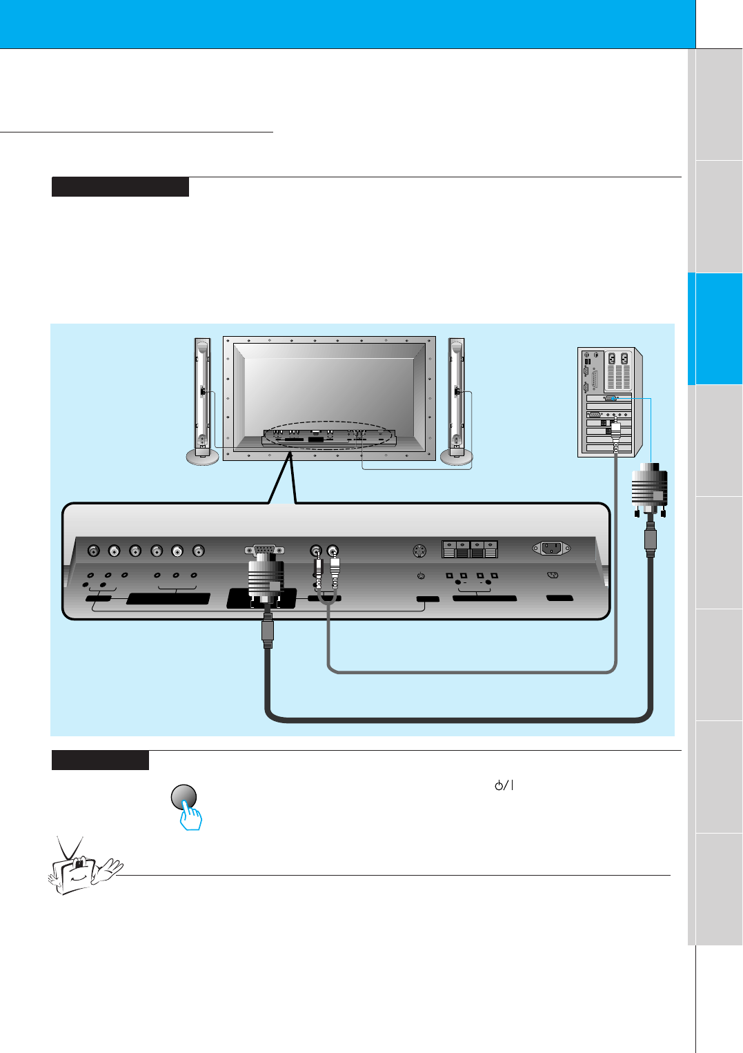
PC Setup
-See your computer’s image on the Monitor.
•Press POWER button on the PC and press ON/OFF button
on the Monitor. After this press button on the Monitor or
press power on button on the remote control.
•Press video/pc button on the remote control to select
RGB.
•Set the resolution of PC under SXGA (1280x1024). (Refer
to page 20.)
video/pc
<On the remote control>
How to connect
How to use
Make the connections shown in the illustration below
• Set the computer video output to UXGA; for the best picture quality. (If the video output of the
PC is not compatible with the Monitor, no picture will appear on the Monitor. See page 20.)
•As shown below, connect the video output port of the PC to the Monitor RGB-PC
INPUT(VGA/SVGA/CGA/SXGA) RGB-DTV INPUT(480p/720p/1080i).
• Connect the audio out from the PC to the Audio jacks on the Monitor. (Audio cables not included
with the Monitor)
•If available, adjust PC sound to your preference.
(+) ( ) (+)( )
AUDIO
(MONO)
R L VIDEO Y PB R
P
AV INPUT
AUDIO
R L RL
EXTERNAL SPEAKER (8Ω) AC INPUTAUDIO INPUT S-VIDEO
COMPONENT (480i/480p/720p/1080i) RGB-PC INPUT
(VGA/SVGA/XGA/SXGA)
RGB-DTV INPUT
(480p/720p/1080i)
(DVD/DTV INPUT)
(+) ( ) (+)( )
AUDIO
(MONO)
R L
AV INPUT
COMPONENT (480i/480p/720p/1080i)
(DVD/DTV INPUT)
RGB-PC INPUT
R
AUDIO INPUT
S-VIDEO
EXTERNAL SPEAKER
(8Ω)
R L
AC INPUT
L
AUDIO
(VGA/SVGA/XGA/SXGA)
RGB-DTV INPUT
(480p/720p/1080i)
VIDEO Y P
B
P
R
Tips
• To avoid burning an image on the Monitor screen, don’t have a still picture on the screen
for a long period time.
< Back panel of the Monitor>
20
Monitor Image Display Specifications
640x350
720x400
31.468 70.09
37.861 85.08
31.469 70.08
37.927 85.03
31.469 59.94
35.000 66.66
37.861 72.80
37.500 75.00
43.269 85.00
45.913 90.03
53.011 100.04
64.062 120.00
35.156 56.25
37.879 60.31
48.077 72.18
46.875
832x624
1024x768
1152x864
1152x870
1280x960
1280x1024
75.00
53.674 85.06
56.000 90.00
64.016 100.00
49.725 74.55
48.363 60.00
56.476 70.06
60.023 75.02
68.677 84.99
54.348 60.05
63.995 70.01
67.500 75.00
77.487 85.05
68.681 75.06
60.000 60.00
75.000 75.00
63.981 60.02
79.976 75.02
Resolution
Horizontal
Frequency (KHz) Vertical
Frequency (Hz)
640x480
800x600
21
First step Composition Connection Basic function Time setting Picture & Sound Special function Others
3
2
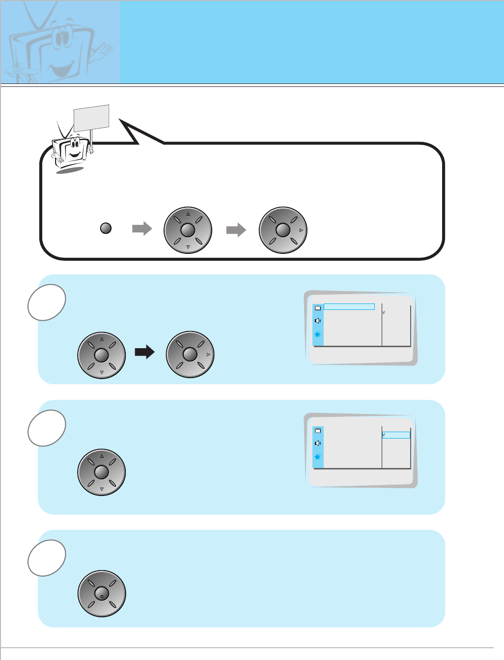
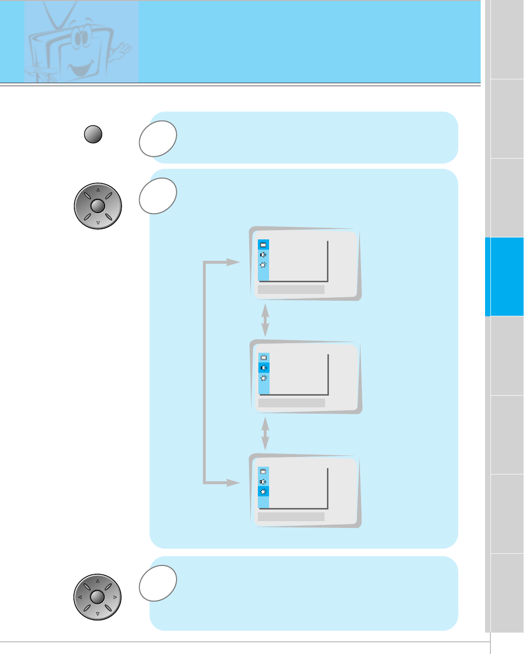
PC Computer Mode Feature Check
-Select RGB first, see page 11.
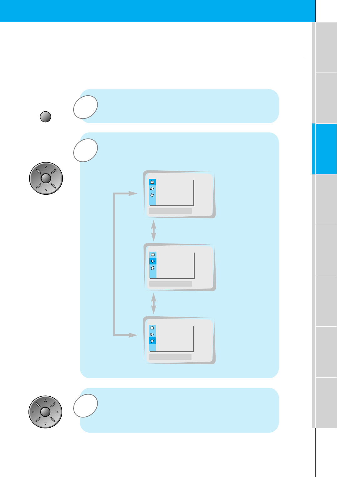
1Press the menu button to show menus on screen.
Press the vol ( G)button and then press the
up/down or vol button to select a feature you want
to use.
•Press the enter button to remove menus.
Press the up/down button to select menus.
•Each press will cycle through the different menus as shown below.
APC G
DRP G
CONTRAST 100 G
BRIGHTNESS 50 G
COLOR 50 G
TINT 0 G
SHARPNESS 50 G
MOVE GNEXT AEXIT
PICTURE
D
E
DASP G
AVL G
TREBLE 50 G
BASS 50 G
BALANCE 0 G
MOVE GNEXT AEXIT
SOUND
D
E
LANGUAGE G
ARC G
SCREEN G
TRANSPARENCY G
PIP/DW G
MOVE GNEXT AEXIT
SPECIAL
D
E
<Picture menu>
<Sound menu>
<Special menu>
menu
up
down
up
down
vol vol
22
1
3
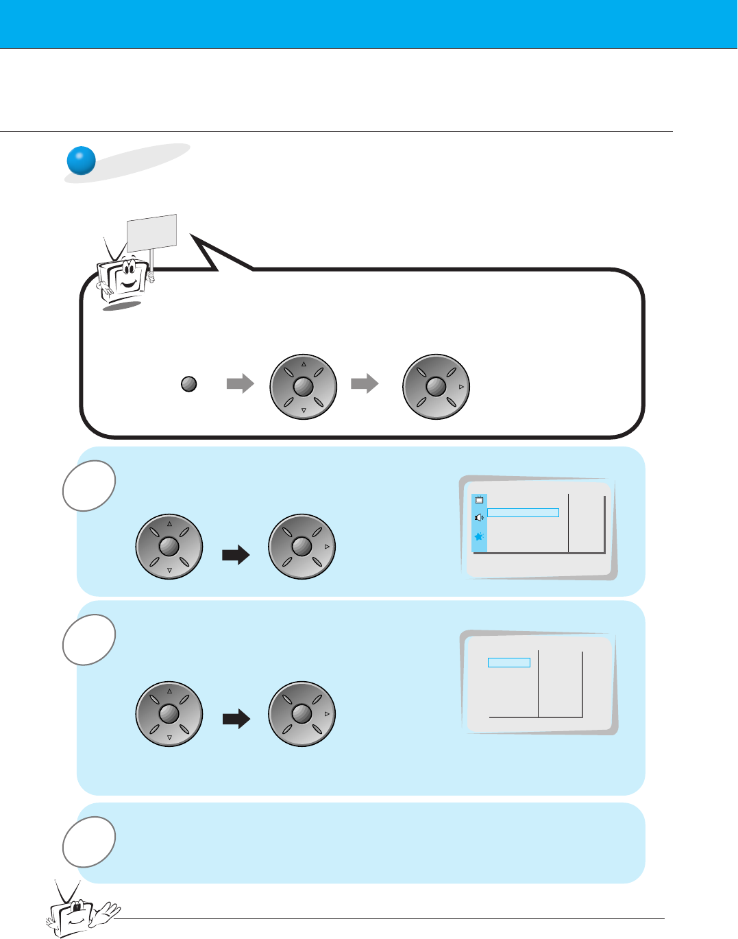
PC Computer Mode Adjustments
Press the up/down button to select SCREEN
and then press the vol ( G) button.
If picture needs to be adjusted more after auto adjustment, adjust H-
POSITION, V-POSITION and PHASE. See following pages.
-The position and trembling of picture is automatically adjusted.
Auto adjustment
READY
Press the menu button and then press the up/down button
to select SPECIAL menu.
Press the vol ( G) button.
2Press the up/down button to select
AUTO.CONFIG. and then press the vol
( G) button.
•If adjustment of AUTO.CONFIG. is finished, it displayed OK.
•If the position of the screen is incorrect, operate the adjustment repeatly.
LANGUAGE
G
CAPTION
G
AUTO OFF
G
SCREEN
G
RGB-OUTPUT
G
AUTO.CONFIG.
G
V-POSITION
G
H-POSITION
G
PHASE
G
RESET
G
G
TO SET
AUTO.CONFIG.
LANGUAGE G
ARC G
SCREEN G
TRANSPARENCY G
PIP/DW G
G
TO SET
SPECIAL
SCREEN
menu up
down
vol
up
down
vol
up
down
vol
Tips
• It’s not out of order even though the screen is displayed odd on AUTO.CONFIG.
23
First step Composition Connection Basic function Time setting Picture & Sound Special function Others
3
2
1
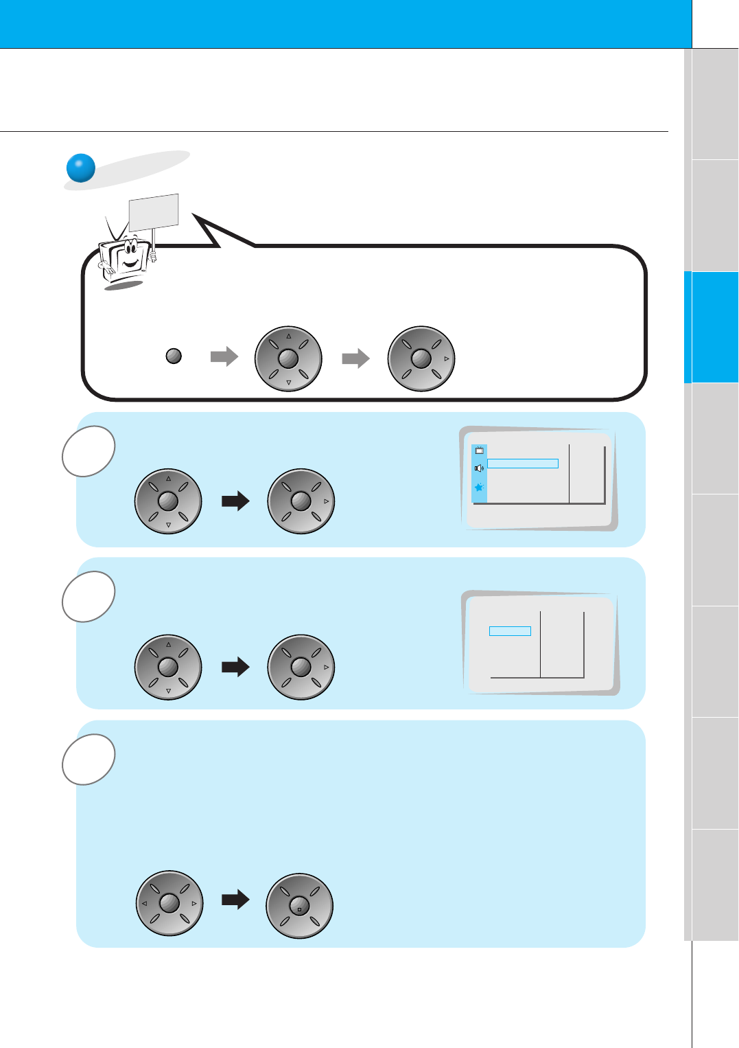
PC Computer Mode Adjustments
Press the up/down button to select SCREEN
and then press the vol ( G) button.
Adjusting horizontal / vertical postion
READY
Press the up/down button to select V-POSI-
TION or H-POSITION and then press the vol
( G) button.
•The adjustment range of V-POSITION is -50 ~ +50.
• The adjustment range of H-POSITION is -100 ~ +100.
•According to the input mode, the adjustment range of V-POSITION/H-POSITION
will be change.
• According to the input signal, the position of the picture will not change even
though adjusting the horizontal or vertical position with this function.
Press the vol button to adjust until you get desired horizontal or verti-
cal position and then press the enter button to remove menus.
Press the menu button and then press the up/down button
to select SPECIAL menu.
Press the vol ( G) button.
LANGUAGE
G
CAPTION
G
AUTO OFF
G
SCREEN
G
RGB-OUTPUT
G
AUTO.CONFIG.
G
V-POSITION
G
H-POSITION
G
PHASE
G
RESET
G
0
V-POSITION
LANGUAGE G
ARC G
SCREEN G
TRANSPARENCY G
PIP/DW G
G
TO SET
SPECIAL
SCREEN
menu up
down
vol
up
down
vol
up
down
vol
enter
vol vol
24
3
2
1Use the up/down button to select SCREEN
and then press the vol ( G) button.
Picture Phase Adjustments
READY
•If the picture isn’t clear after auto adjustment and especially if the characters are still trembling, then
adjust the picture phase manually.
Initializing
• To initialize the adjusted value, select RESET with the up/down button and
then press the vol (G) button.
Use the up/down button to select PHASE
and then press the vol ( G) button.
•The adjustment range of PHASE is 0 ~ 63.
Press the vol button to adjust phase and then press the enter button.
LANGUAGE
G
CAPTION
G
AUTO OFF
G
SCREEN
G
RGB-OUTPUT
G
AUTO.CONFIG.
G
V-POSITION
G
H-POSITION
G
PHASE
G
RESET
G
30
Press the menu button and then press the up/down button
to select SPECIAL menu.
Press the vol ( G) button.
PHASE
LANGUAGE G
ARC G
SCREEN G
TRANSPARENCY G
PIP/DW G
G
TO SET
SPECIAL
SCREEN
menu up
down
vol
up
down
vol
up
down
vol
enter
vol vol
25
First step Composition Connection Basic function Time setting Picture & Sound Special function Others
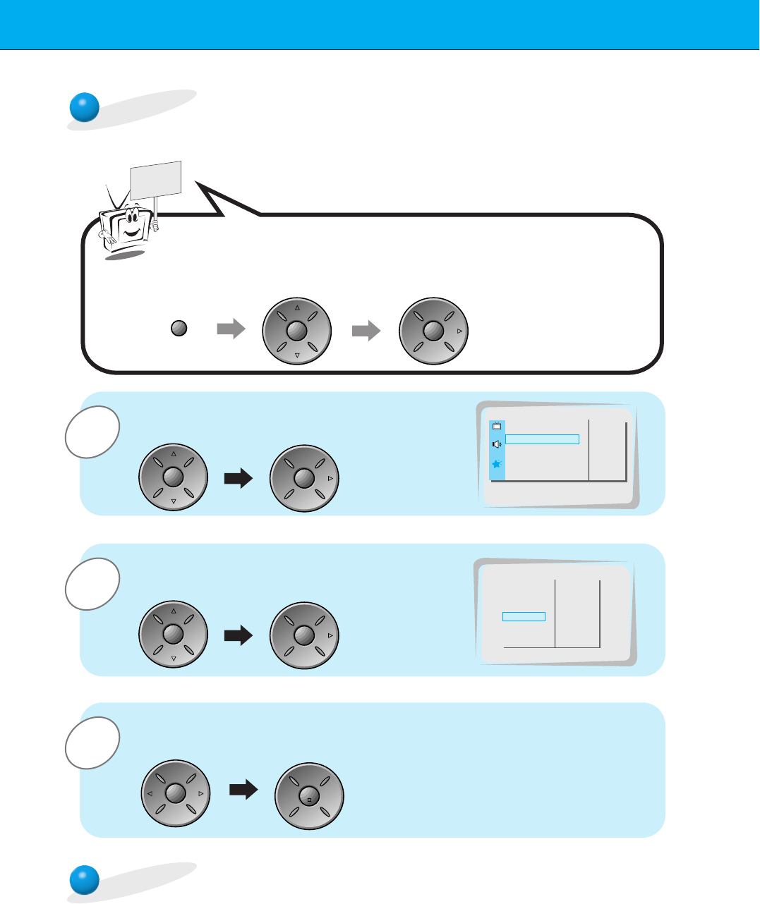
PIP function
-Make sure to select RGB before operating.
- This function works only in the following resolution;
640x480, 800x600, 1024x768(only in Vertical frequency 60 Hz)
- When you select RGB or DTV for main picture in PIP/Twin picture, you can watch video, cable
TV or DVD for sub picture.
- It’s not out of order even though color of main picture is differ from PIP’s in PIP/Twin picture.
- If input mode of main picture change in PIP/Twin picture, sub picture disappeared automatically.
- When watching PIP/Twin picture, SCREEN is inactivated in special menu.
pip
Watching the PIP (Picture in Picture)
Press the pip button.
•Each time you press pip or vol button, you can change the
PIP size as below.
PIP (S) PIP (L) OFF
PIP
F
PIP (S)
G
PIP
F
PIP (L)
G
PIP
F
OFF
G
<Small PIP>
<Large PIP>
<Off>
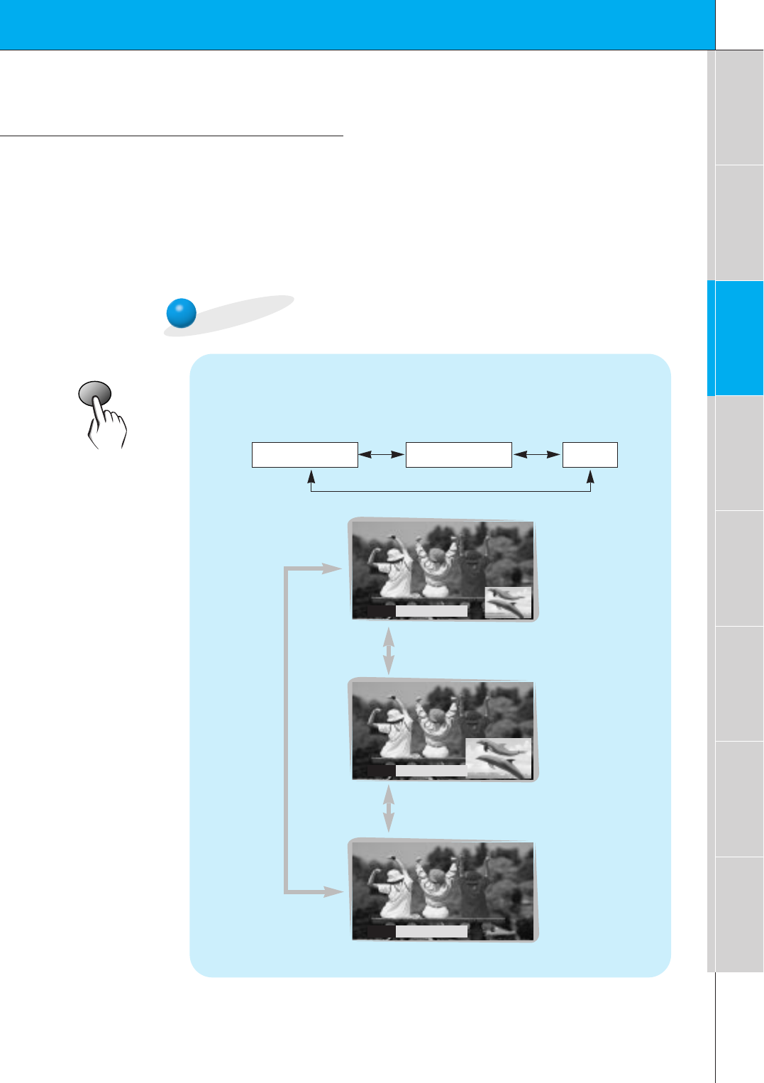
26
input select
Selecting the input signal
Press the input select button in PIP mode.
•Each time you press input eslect button, you can select
VIDEO or COMPOENT alternatively.
In case of COMPOENT, this function works only in 480i mode.
VIDEO COMPONENT
PIP INPUT
F
VIDEO
G
position
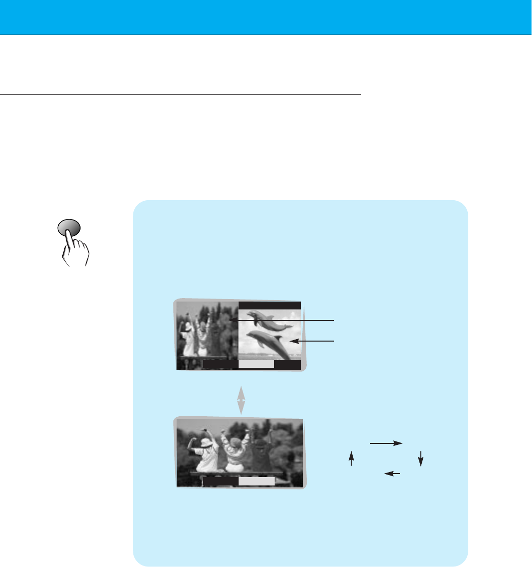
Moving the Sub picture
Press the position button in PIP mode.
•Each press of the position button change the position of the
sub picture as below.
27
First step Composition Connection Basic function Time setting Picture & Sound Special function Others
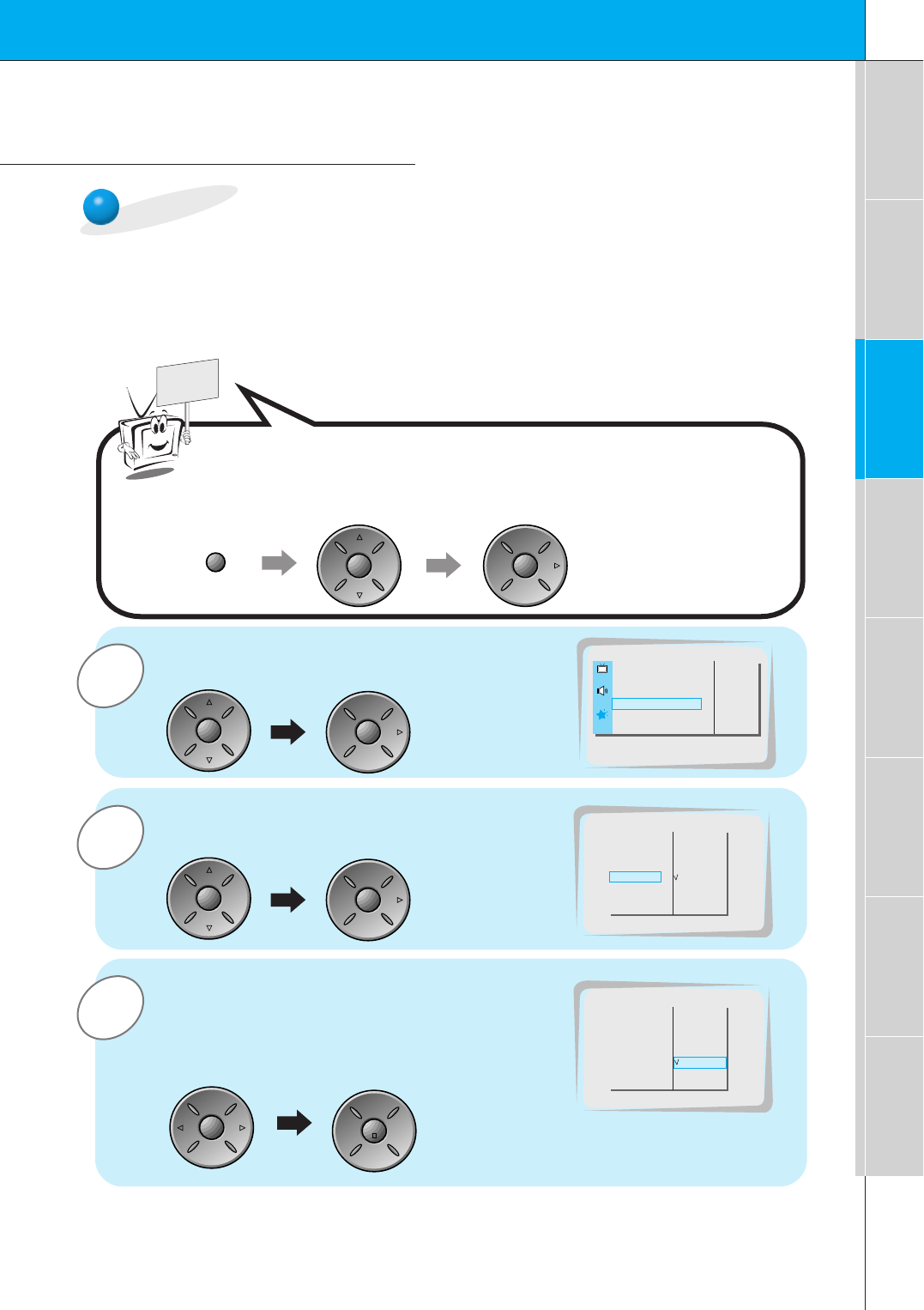
PIP function
3
2
1Use the up/down button to select PIP/DW
and then press the vol ( G) button.
READY
Use the up/down button to select SOUND
SELECT and then press the vol ( G) button.
•Each time you press D / E button, you can
select SOUND (L) or SOUND (S) alternatively.
Press the vol button to select SOUND (M) or
SOUND (S) and then press the enter button.
LANGUAGE
G
CAPTION
G
AUTO OFF
G
SCREEN
G
RGB-OUTPUT
G
DW
G
PIP
G
INPUT
G
SOUND SELECT
G
POSITION
G
SOUND (M)
SOUND (S)
Press the menu button and then press the up/down button
to select SPECIAL menu.
Press the vol ( G) button.
SOUND SELECT
LANGUAGE
G
CAPTION
G
AUTO OFF
G
SCREEN
G
RGB-OUTPUT
G
DW
G
PIP
G
INPUT
G
SOUND SELECT
G
POSITION
G
SOUND (M)
SOUND (S)
LANGUAGE G
ARC G
SCREEN G
TRANSPARENCY G
PIP/DW G
G
TO SET
SPECIAL
PIP/DW
menu up
down
vol
up
down
vol
up
down
vol
enter
vol vol
-This function works only in the following resolution;
640x480, 800x600, 1024x768(only in Vertical frequency 60 Hz)
- To use this function, connect PC/DTV video input to RGB-PC
INPUT(VGA/SVGA/XGA/SXGA) RGB-DTV INPUT(480p,/720p/1080i) socket and connect
PC/DTV audio inputs to AUDIO INPUT.
Selecting the sound items
SOUND (S)
28
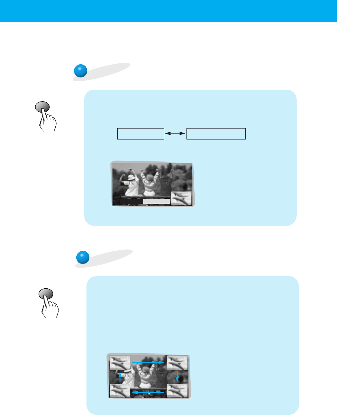
Twin picture function
-Make sure to select RGB before operating.
- This function works only in the following resolution;
640x480 (only in Vertical frequency 60 Hz)
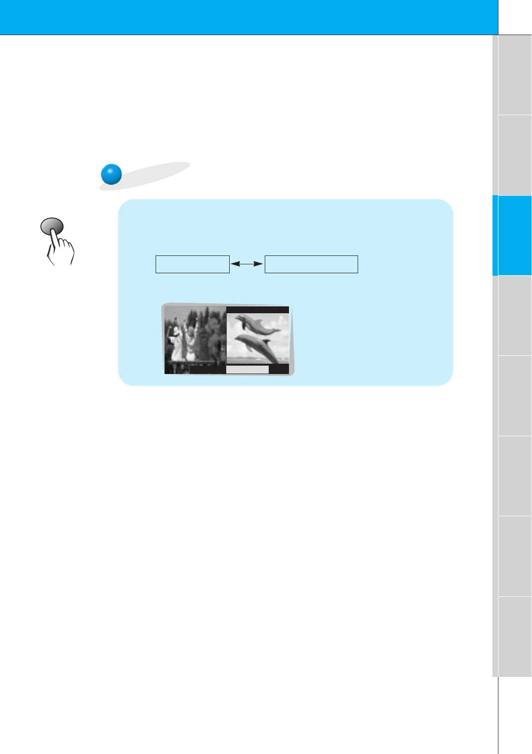
twin picture
Press the twin picture button.
•Each time you press twin picture or vol button, you can
select ON or OFF.
<ON>
<OFF>
DW
F
OFF
G
DW
F
ON
G
• To avoid showing a fixed
image on the screen, sub
picture moves every 2
hours.
:Center Upside
Downside Center
Sub picture
Main picture
29
First step Composition Connection Basic function Time setting Picture & Sound Special function Others
input select
Selecting the input signal
Press the input select button in TWIN PICTURE mode.
•Each time you press input eslect button, you can select
VIDEO or COMPOENT alternatively.
In case of COMPOENT, this function works only in 480i mode.
VIDEO COMPONENT
PIP INPUT
F
VIDEO
G
30
Using the remote control
Installing batteries
• Open the battery compartment cover on the back
of the remote control and insert the batteries with
correct polarity, match “+” with “+”, and match “-”
with “-”.
• Install two 1.5V “AA” alkaline batteries.
Don’t mix the used batteries with new batteries.
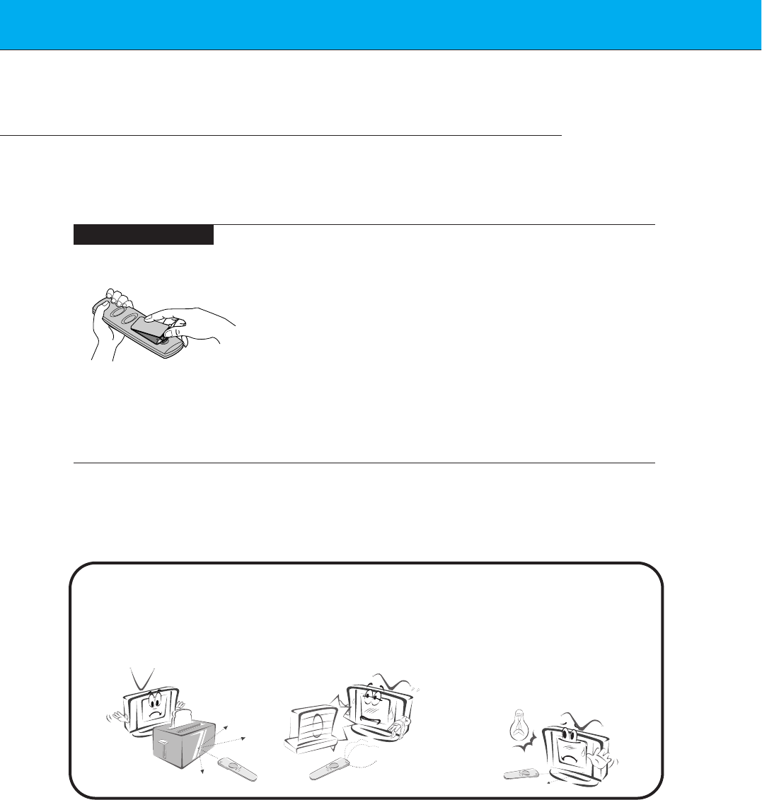
Notes for using the remote control
Make sure these are no
objects between the
remote control and its
sensor.
Don’t place the remote control
near a heater or damp place.
Strong impact on the remote con-
trol may cause operation failure.
Signal from the remote control
may be disturbed by sun light or
other strong light. In this case,
turn the set to other direction.
31
First step Composition Connection Basic function Time setting Picture & Sound Special function Others
Turning on the Monitor
3
2
1
2
1
- When using the remote control, aim it at its sensor on the Monitor.
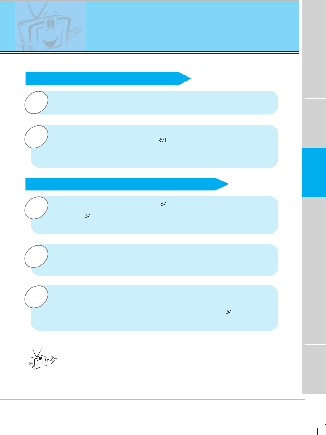
Turning on the Monitor just after installation
Turning on the Monitor (power cord is still connected)
Connect power cord correctly.
Press the ON/OFF button on the Monitor. At this moment, the Monitor is
switched to standby mode. Press the or INPUT SELECT button on the
Monitor or press the power on or video/pc button on the remote control and
then the Monitor will be switched on.
Press the or INPUT SELECT button on the Monitor or press the power on
or video/pc button on the remote control and then the Monitor will be switched
on.
If the Monitor is turned off with the button on the Monitor
• Press the ON/OFF button on the Monitor to turn on the Monitor.
If the Monitor is turned off with the ON/OFF button on the Monitor
• Press the ON/OFF button on the Monitor and then press the or INPUT
SELECT button on the Monitor or press the power on or video/pc button on
the remote control and then the Monitor will be switched on.
If the Monitor is turned off with the remote control and also the ON/OFF
button on the Monitor
Tips
•Adjusting volume level
Volume(GG) button increases the level of sound and volume(FF) button
decreases the level of sound.
32
Selecting language for the menus
3
2
1
READY
Press the up/down button to select
LANGUAGE and then press the
vol ( G) button.
Press the up/down button to select the
desired language.
Press the enter button.
Press the menu button and then press the up/down button to
select SPECIAL menu.
Press the vol ( G) button.
LANGUAGE G
ARC G
SCREEN G
TRANSPARENCY G
PIP/DW G
ENGLISH
ESPAÑOL
PORTUGUÊS
FRANÇAIS
SPECIAL
LANGUAGE
˙–„
LANGUAGE G
ARC G
SCREEN G
TRANSPARENCY G
PIP/DW G
ENGLISH
ESPAÑOL
PORTUGUÊS
FRANÇAIS
SPECIAL
˙–„
ENGLISH
menu up
down
vol
up
down
vol
up
down
enter
33
First step Composition Connection Basic function Time setting Picture & Sound Special function Others
1
3
2
Press the menu button.
Press the up/down button.
•Each press will cycle through the menus shown below.
Checking features
Press the vol ( G) button and then press the
up/down or vol button to select a function you
want to use.
•Press the enter button to remove menus.
APC G
DRP G
CONTRAST 100 G
BRIGHTNESS 50 G
COLOR 50 G
TINT 0 G
SHARPNESS 50 G
MOVE GNEXT AEXIT
PICTURE
D
E
DASP G
AVL G
TREBLE 50 G
BASS 50 G
BALANCE 0 G
MOVE GNEXT AEXIT
SOUND
D
E
LANGUAGE G
ARC G
SCREEN G
TRANSPARENCY G
PIP/DW G
MOVE GNEXT AEXIT
SPECIAL
D
E
<Picture menu>
<Sound menu>
<Special menu>
menu
up
down
up
down
vol vol
34
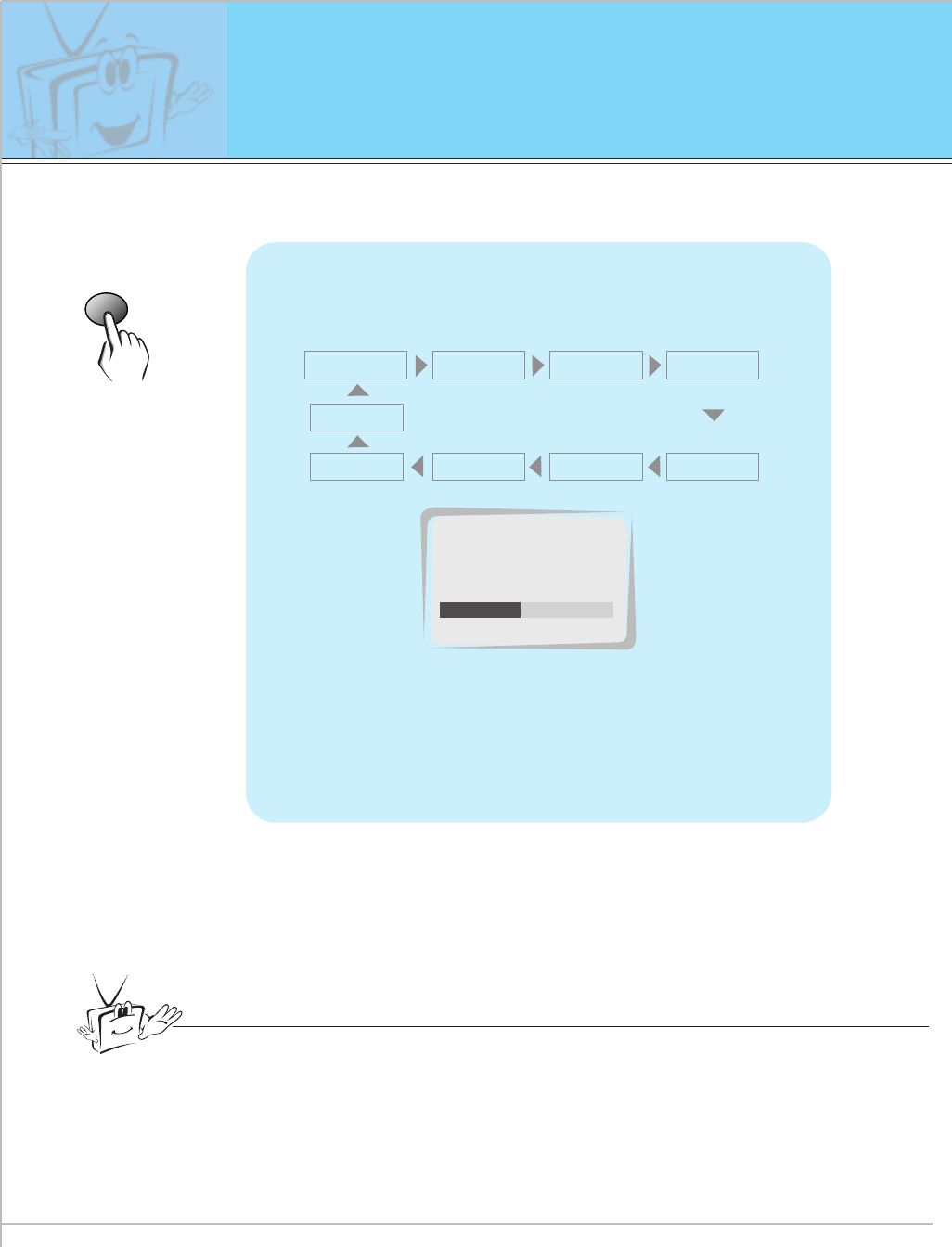
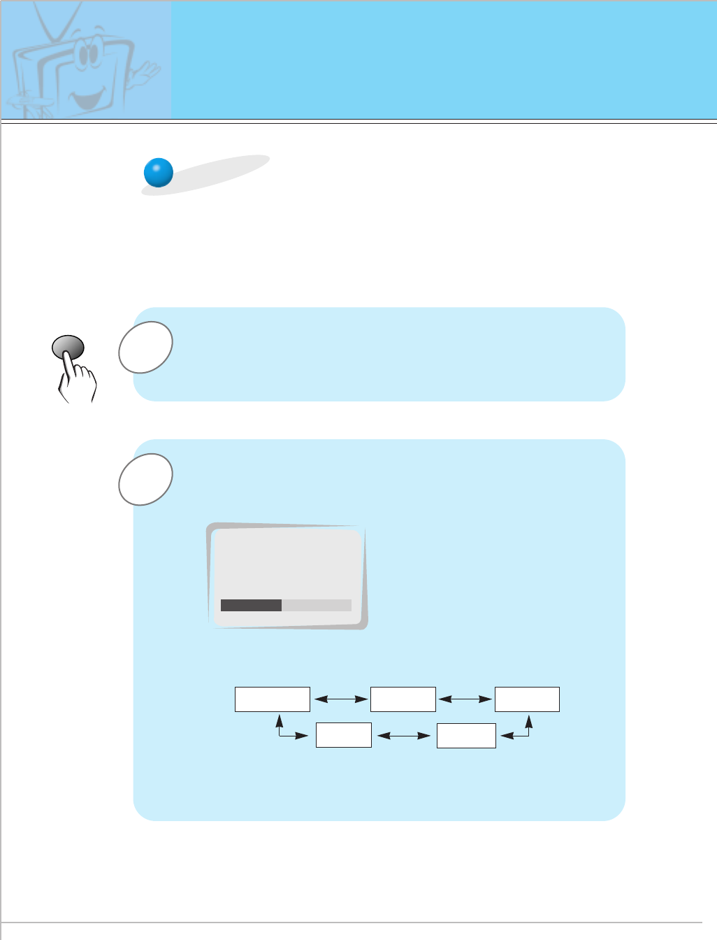
Setting sleep time
<This feature automatically turns the Monitor off after a preset time.
>
Press the sleep button to set sleep time.
Each time you press the next preset setting
time is changed as shown below.
• To release sleep time setting, press the sleep or
vol button repeatedly to select F--- G.
sleep
F--- G F 10 GF20 G F 30 G
F120 GF 180 G
F240 G
F90 G F 60 G
Tips
•When the sleep time you want is displayed on the screen, don’t press the
sleep button. The screen display disappears and sleep time is to be set.
• To check remaining sleep time after setting, press the sleep or enter button
just once.
• If you turn the Monitior off after setting the sleep timer, the setting will be
erased. The sleep timer will then have to be set again.
F 30 G
SLEEP
35
First step Composition Connection Basic function Time setting Picture & Sound Special function Others
2
1
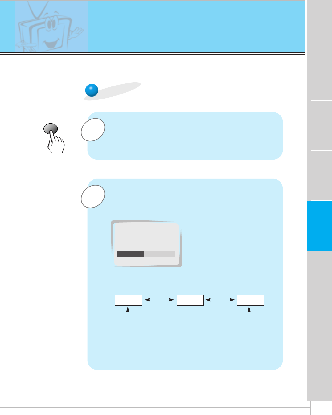
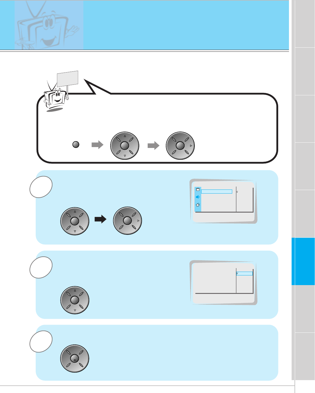
apc
APC (Auto Picture Control)
Press the apc button.
Press the apc or vol button to select your desired
picture condition.
•Each press of vol button changes the screen display as
below.
• You can also select CLEAR, SOFT or USER in the PIC-
TURE menu.
CLEAR SOFT USER
F CLEAR G
APC
Auto picture control
< APC sets the Monitor with the best picture appearance >
-This function isn’t select in RGB, PIP/TWIN PICTURE.
36
2
1
READY
Press the up/down button to select
CONTRAST and then press the vol ( G)
button. (in case of adjusting contrast)
•Adjust BRIGHTNESS, COLOR, TINT and
SHARPNESS in the same way.
Press the vol button to make appropri-
ate adjustment and then press the
enter button.
•Press the up/down button to select other items.
Press the menu button and then press the up/down button to
select PICTURE menu.
Press the vol ( G) button.
Adjusting picture appearance
APC G
DRP G
CONTRAST 100 G
BRIGHTNESS 50 G
COLOR 50 G
TINT 0 G
SHARPNESS 50 G
PICTURE
CONTRAST 100
APC G
DRP G
CONTRAST 70 G
BRIGHTNESS 50 G
COLOR 0 G
TINT 0 G
SHARPNESS 50 G
PICTURE
menu up
down
vol
up
down
vol
vol vol enter
- You can’t adjust contrast, brightness, color, tint, sharpness in sub picture for PIP / Twin picture.
37
First step Composition Connection Basic function Time setting Picture & Sound Special function Others
DRP (Digital Reality Picture)
< This function stresses picture outline in showing a dark area light >
3
1
READY
Press the up/down button to select
DRP and then press the vol ( G)button.
Press the enter button.
Press the menu button and then press the up/down button to
select PICTURE menu.
Press the vol ( G) button.
APC G
DRP G
CONTRAST 100 G
BRIGHTNESS 50 G
COLOR 50 G
TINT 0 G
SHARPNESS 50 G
CLEAR
SOFT
PICTURE
DRP
2Press the up/down button to select
CLEAR or SOFT.APC G
DRP G
CONTRAST 100 G
BRIGHTNESS 50 G
COLOR 50 G
TINT 0 G
SHARPNESS 50 G
CLEAR
SOFT
PICTURE
CLEAR
menu up
down
vol
up
down
vol
up
down
enter
38
3
2
1
READY
Press the up/down button to select
SCREEN and then press the
vol ( G) button.
Press the D / Ebutton to select TV or
VCR.
•Select the VCR to stable condition of picture
when you are watching VCR.
• Select the TV in case of connecting external
equipment to monitor.(Except VCR)
• Each time you press the D / Ebutton you can
select TV or VCR alternatively.
Press the enter button.
Press the menu button and then press the up/down button to
select SPECIAL menu.
Press the vol ( G) button.
LANGUAGE G
ARC G
SCREEN G
TRANSPARENCY G
PIP/DW G
TV
VCR
SPECIAL
SCREEN
LANGUAGE G
ARC G
SCREEN G
TRANSPARENCY G
PIP/DW G
TV
VCR
SPECIAL
VCR
menu up
down
vol
up
down
vol
up
down
enter
Selecting the screen item
- This function work only in video mode.
39
First step Composition Connection Basic function Time setting Special function Others
Picture & Sound
Adjusting sound appearance
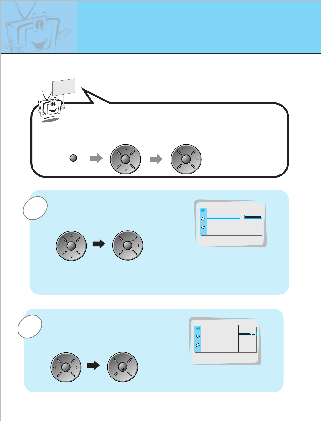
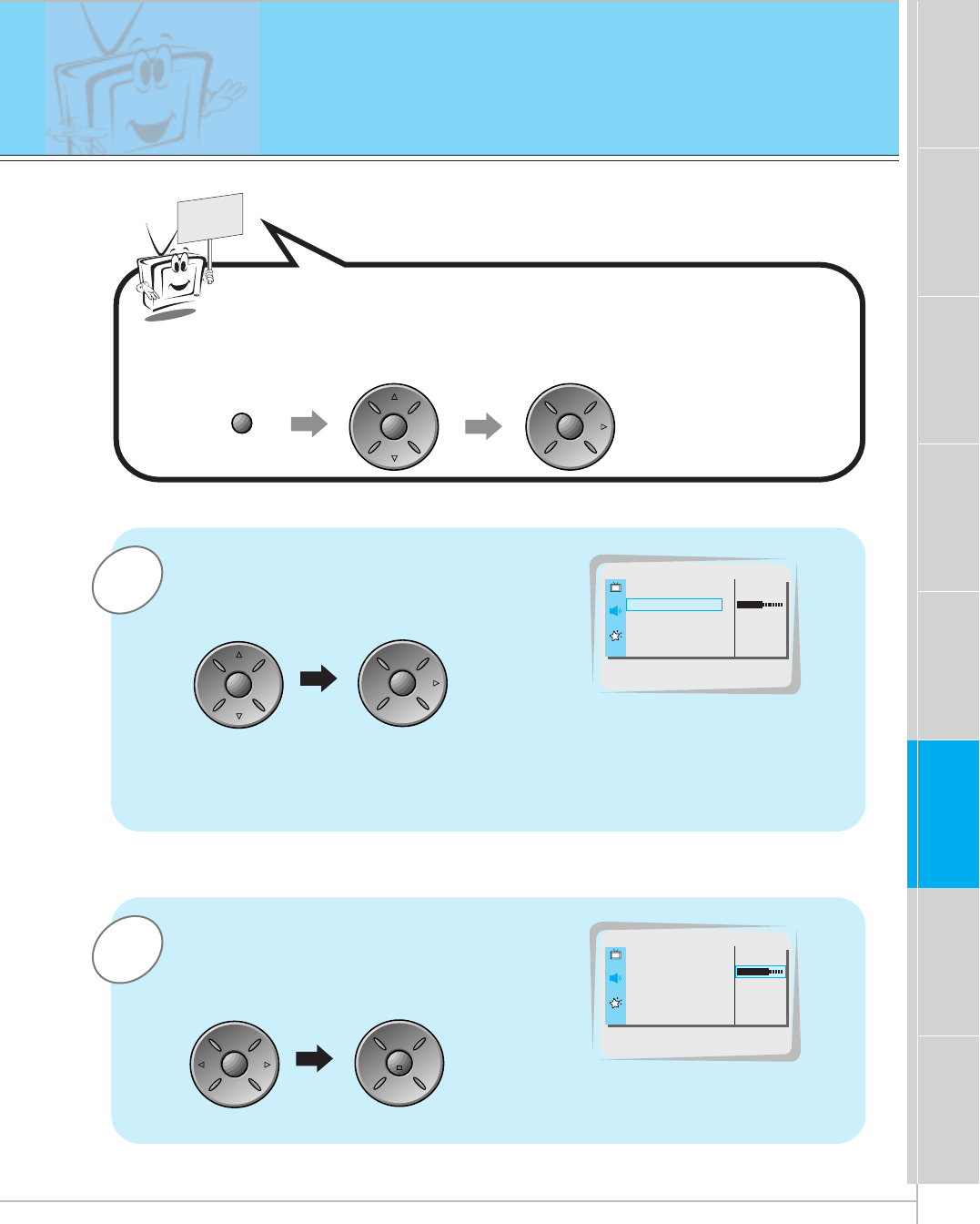
2
1
READY
Press the up/down button to select
TREBLE and then press the vol ( G)
button. (in case of adjusting treble)
•Adjust BASS and BALANCE in the same way.
Press the vol button to make appropri-
ate adjustment and then press the
enter button.
•Press the up/down button to select other items.
Press the menu button and then press the up/down button to
select SOUND menu.
Press the vol ( G) button.
DASP G
AVL G
TREBLE 50 G
BASS 50 G
BALANCE 0 G
SOUND
TREBLE 50
DASP G
AVL G
TREBLE 70 G
BASS 50 G
BALANCE 0 G
SOUND
menu up
down
vol
up
down
vol
vol vol enter
40
Auto sound control
DASP
•This function lets you enjoy the best sound without any special adjust-
ment because the Monitor automatically adjusts the sound appropriate
to viewing program character by self-intelligence.
1
easy sound
Press the easy sound button.
2Press the easy sound or vol button to select your
desired sound.
•Each press of easy sound or vol button changes the
screen display as below.
• You can also select FLAT, SPORTS, CINEMA, MUSIC or
USER in the SOUND menu.
FLAT SPORTS
USER
CINEMA
MUSIC
F USER G
DASP
41
First step Composition Connection Basic function Time setting Special function Others
Picture & Sound
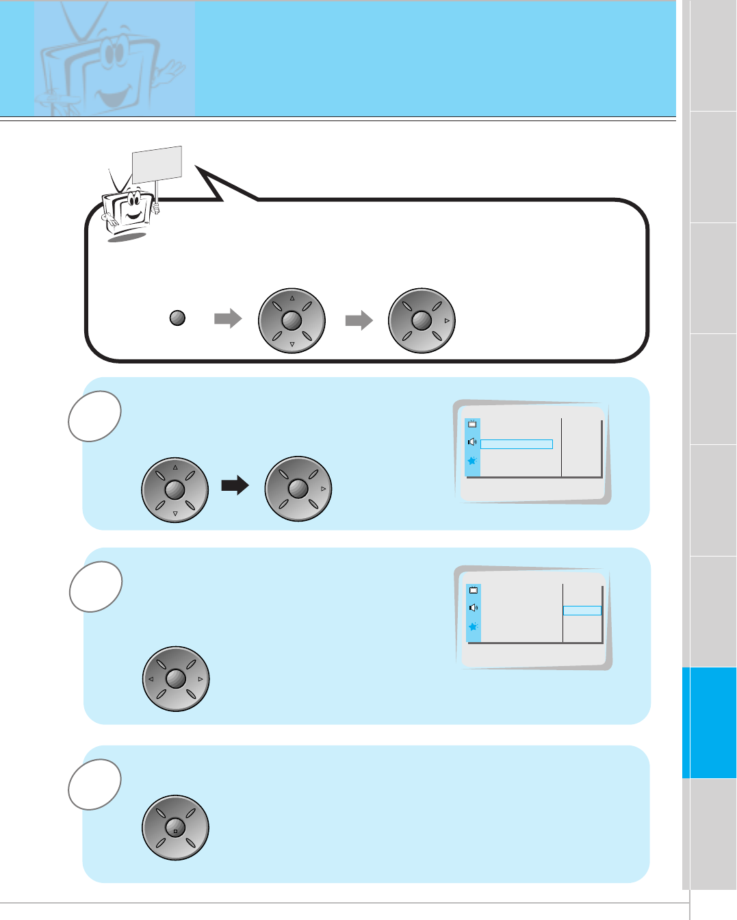
AVL (Auto Volume Leveler)
< This function keeps on an equal volume level even if you change channels>
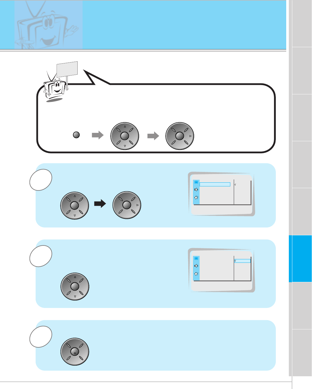
3
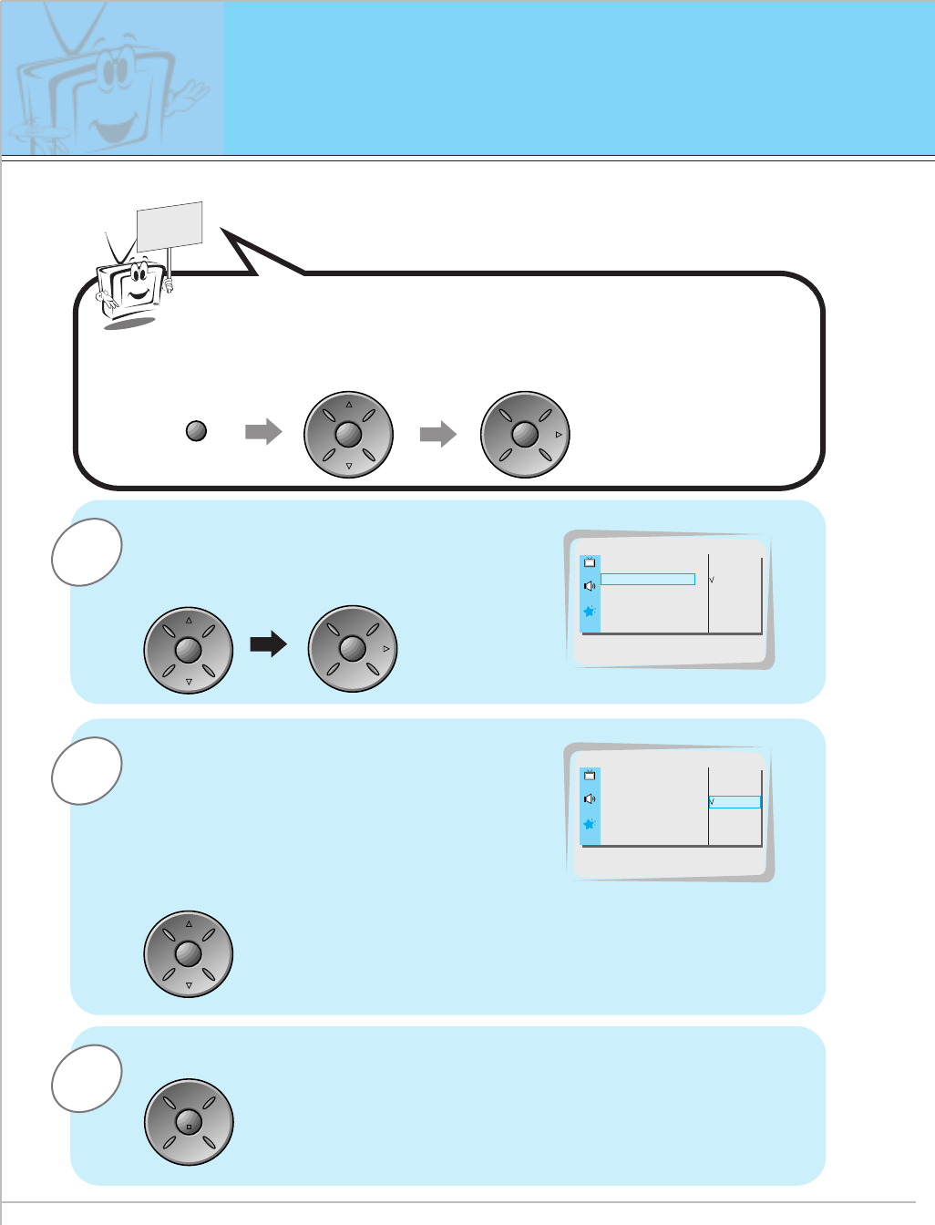
1
READY
Press the up/down button to select
AVL and then press the vol ( G)
button.
Press the enter button.
Press the menu button and then press the up/down button to
select SOUND menu.
Press the vol ( G) button.
DASP G
AVL G
TREBLE 50 G
BASS 50 G
BALANCE 0 G
ON
OFF
SOUND
AVL
2Press the up/down button to select
ON or OFF.
ON
OFF
SOUND
ON
DASP G
AVL G
TREBLE 50 G
BASS 50 G
BALANCE 0 G
menu
up
down
vol
up
down
vol
up
down
enter
-This function works only in case of connecting a cable box with the monitor.
42
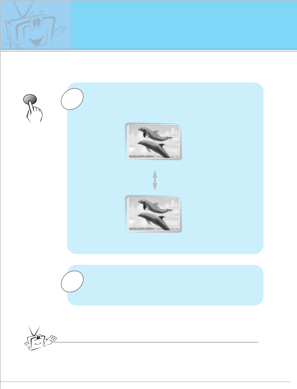
Using Still function
1
2
freeze
Press the freeze button.
• You can still the current picture.
• The sub picture is stilled in PIP or Twin picture mode.
<Moving image>
<Still image>
To finish this function, press the freeze button again.
Tips
•If still picture is on the screen for more than 5 minutes, the screen gets dark.
Any function is activated, the brightness of the screen gets restored.
• This function don’t worked in RGB mode.
-This function doesn’t work in RGB.
43
First step Composition Connection Basic function Time setting Picture & Sound Others
Special function
Adjusting OSD Transparency
3
2
1
READY
Press the up/down button to select
TRANSPARENCY and then press the
vol ( G) button.
Press the vol button to adjust OSD
transparency.
•The adjustment range of TRANSPARENCY
is 0 ~ 5.
Press the enter button.
Press the menu button and then press the up/down button to
select SPECIAL menu.
Press the vol ( G) button.
LANGUAGE G
ARC G
SCREEN G
TRANSPARENCY G
PIP/DW G
5
SPECIAL
TRANSPARENCY
LANGUAGE G
ARC G
SCREEN G
TRANSPARENCY G
PIP/DW G
SPECIAL
3
menu up
down
vol
up
down
vol
vol vol
enter
44
Setting picture format
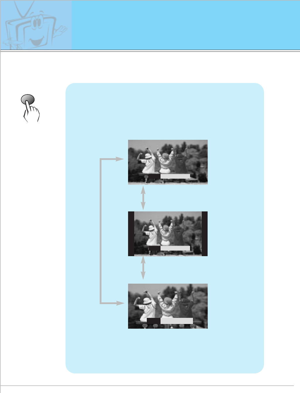
ratio
Press the ratio button to select a desired picture
format.
• You can also select 16:9, 4:3 or ZOOM in the ARC of the
SPECIAL menu.
• Each time you press ratio or vol button, you can select
16:9, 4:3 or ZOOM alternatively.
ARC
F
16 : 9
G
<16:9>
<4:3>
<Zoom>
ARC
F
4 : 3
G
ARC
F
ZOOM
G
- You are available to 16:9 or 4:3 in RGB and 16:9 is only available in DTV 720p/1080i.
- If 4:3 is on the screen for a long time, that fixed image may remain visible.
45
First step Composition Connection Basic function Time setting Picture & Sound Special function Others
Maintenance
Cleaning the screen
1. Here’s a great way to keep the dust off your screen for a while. Wet a
soft cloth in a mixture of lukewarm water and a little fabric softener or
dish washing detergent. Wring the cloth until it’s almost dry, and then
use it to wipe the screen.
2. Make sure the excess water is off the screen, and then let it air-dry
before you turn on your Monitor.
Cleaning the cabinet
To remove dirt or dust, wipe the cabinet with a soft, dry, lint-free cloth.
Please be sure not to use a wet cloth.
Extended absence
If you leave your Monitor dormant for a long time (such as a
vacation), it’s a good idea to unplug the power to protect
against possible damage from lightning or power surges.
- Early malfunction can be prevented. Careful and regular cleaning can extend the amount of
time you will have with your new Monitor. Be sure to turn the power off and pull out the plug
before you begin any cleaning.
46
No output from one
of the speakers • Adjust BALANCE in the SOUND menu. (Refer to p.39)
Strange sound
from the Monitor
•The reason strange sound comes from the Monitor when turn-
ing the Monitor on or off is due to the signals being input or
output to the Monitor.
This strange noise does not mean that the Monitor is faulty.
Troubleshooting check list
No picture &
No sound
•Check whether the Monitor is turned on.
• Check the power cord.
• Plug another product’s power cord into the wall outlet where
the Monitor’s power cord was plugged in.
No or Poor color
or Poor picture
• Select COLOR in the PICTURE menu and press the VOL-
UME (G) button. (Refer to p.36)
• Keep a certain distance between the Monitor and the VCR.
• Activate any function to restore the brightness of the picture.
(If still picture is on the screen for more than 5 minutes, the
screen gets dark.)
The remote control
doesn’t work
•Check to see if there is any object between the Plasma
Display and the remote control causing obstruction.
• Check to see if the batteries are installed with the correct
polarities. (Refer to p.30)
• Replace new batteries. (Refer to p.30)
Picture OK &
No sound •Press the VOLUME (G) button.
47
First step Composition Connection Basic function Time setting Picture & Sound Special function Others
Product specifications
MODEL
Width (inches)
Height (inches)
Depth (inches)
Weight (pounds)
Power consumption (watts)
Power requirement
Resolution
Color
DPDP60W
57.3
34.8
3.9
154.3
320
AC 120V ~ 60Hz
1280 x 720 (Dot)
16,770,000 (256 steps of each R, G and B)
• This product specifications above can be changed without notice for quali-
ty improvement.

PLASMA DISPLAY PANEL
ON/OFF INPUT SELECT VOLUME
P/NO : 3828VA0277B
(NP00KA)
PLASMA DISPLAY PANEL
Please read this owner’s manual carefully before
operating the Monitor.
Retain it for future reference.
Record model number and serial number of the
Monitor.
See the label attached on the back of the Monitor
and quote this information to your dealer when you
require service.
Model number : DPDP60W
Serial number : DPDP60W
OWNER’S MANUAL