LG Electronics USA N1742LET NETWORK MONITOR User Manual Lx6WTG Q ENG
LG Electronics USA NETWORK MONITOR Lx6WTG Q ENG
USERS MANUAL

Make sure to read Safety Precautions before using this product.
Keep the User's Guide (CD) in an accessible place for future reference.
See the attached label on the unit and show this information to your
dealer when asking for service.
With LG Network Monitor, some PC programs may not be compatible
or need to be modified due to different kind of operation.
Please check the compatibility in advance, before purchasing or
installing the software. LG do not have any kind of legal liability on this
matter.
N1742L
N1742LP
N1942L
User’s Guide
Network Monitor
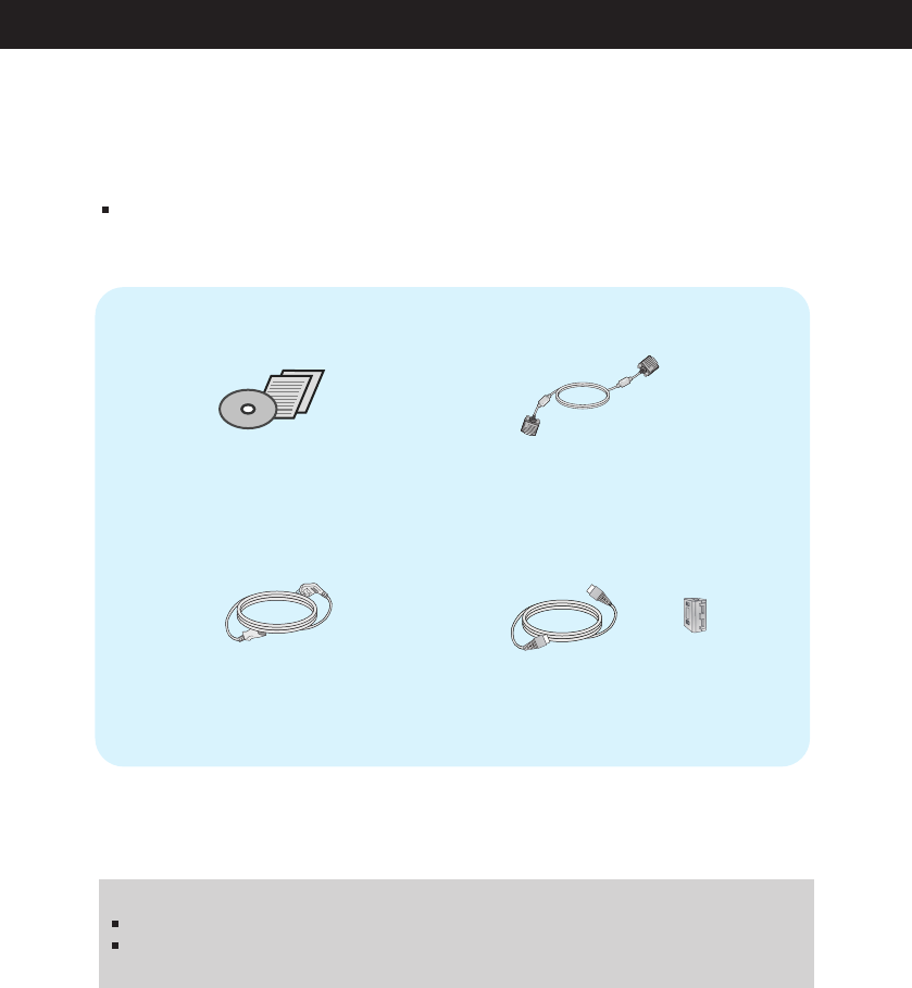
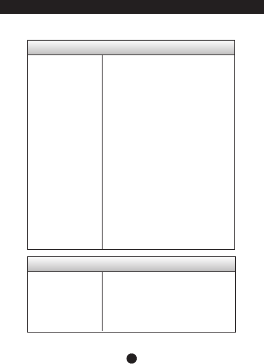
Accessories
!!! Thank for selecting LGE products !!!
Please make sure the following items are included with your
monitor. If any items are missing, contact your dealer.
User's Guide/Cards
Power Cord
(Depending on the country)
15-pin D-Sub Signal Cable
(To set it up, this signal cable may
be attached to this product before
shipping out.)
IMPORTANT
This accessories may look different from those shown here.
User must use shielded signal interface cables (D-sub 15 pin cable, LAN cable) with ferrite
cores to maintain standard compliance for the product.
Lan cable and EMI Core
(These items are not included for all models.)
and

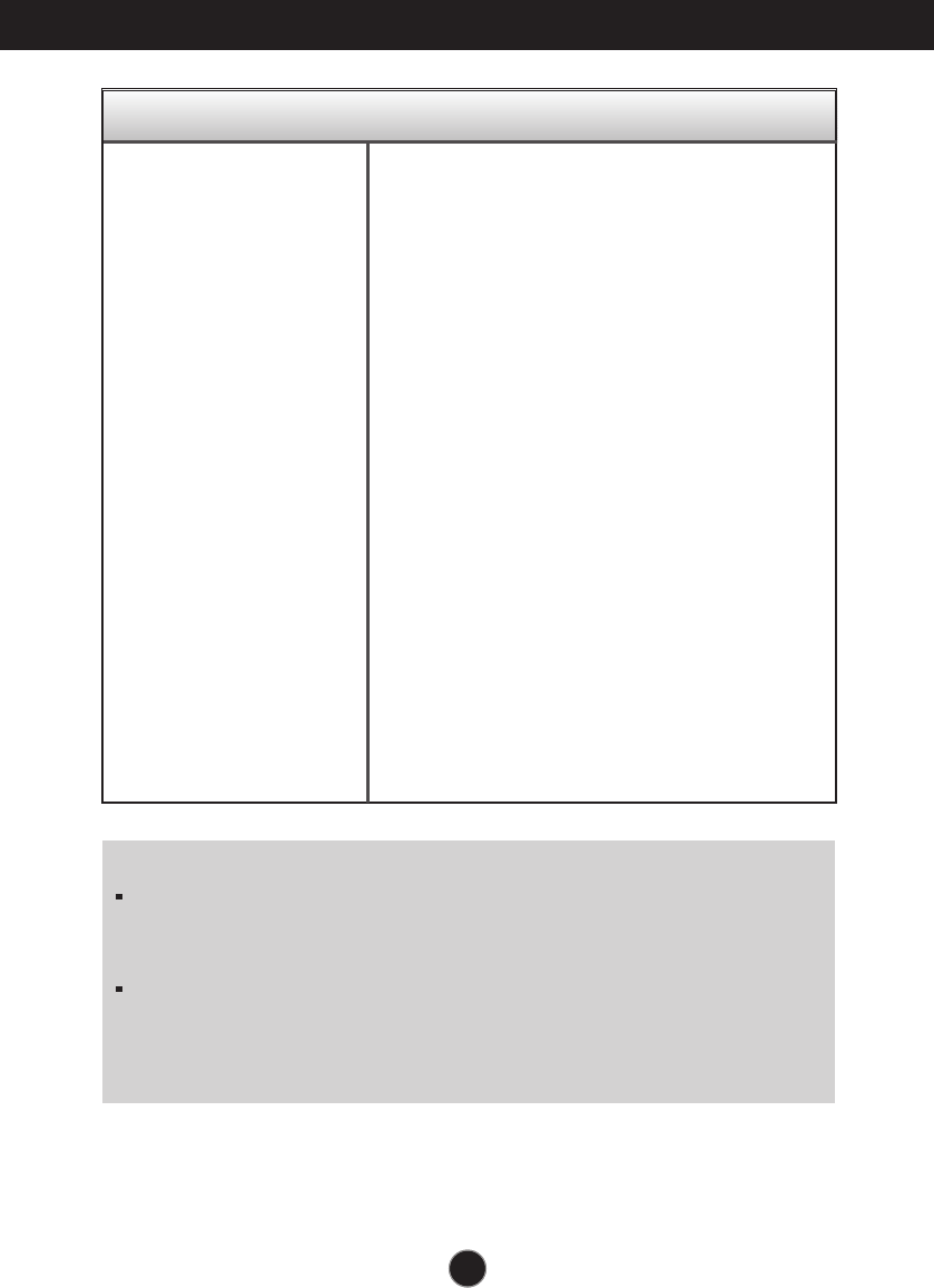
Important Precautions
NOTE
THE MANUFACTURER IS NOT RESPONSIBLE FOR ANY RADIO OR TV
INTRERFERENCE CAUSED BY UNAUTHORIZED MODIFICATIONS TO THIS
EQUIPMENT.SUCH MODIFICATIONS COULD VOID THE USER'S AUTHORITY
NOTE
This epuipment has been tested and found to comply with the limits for a class
B digital device,pursuant to part 15 of the FCC Rules.These limits are designed
to provide reasonable protection against harmful interference in a residential
installation.This equipment generates,uses and can radiate radio frequency
cause harmful interference to radio communications.However,there is no
guarantee that interference will not occur in a particular installation.If this
which can be determined by turning the equipment off and on,the user is
encouraged to try to correct the interference by one or more of the following
measures:
-Reorient or relocate the receiving antenna.
-Increase the separation between the equipment and the receiver.
-Connect the equipment into an outlet on a circuit different from that to which
the receiver is connected.
energy and,if not installed and used in accordance with the instructions,may
equipment does cause harmful interference to radio or television reception,
TO OPERATE THE EQUIPMENT.
-Consult the dealer or an experienced radio/TV technician for help.
A3
A1
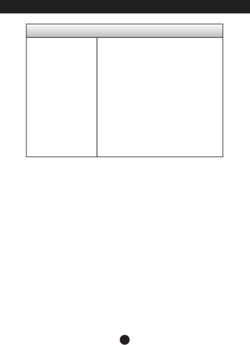
Safety Precautions
Please read these safety precautions carefully before using the product.
Failure to follow those warnings may result in death, serious injury or damage to the
product or other property.
Warning
Electrical Power Related Precautions
Use only the power cord supplied with the unit or another manufacturer authorized cord.
- Failure to do so may result in fire or electrical shock or damage to the product.
Use only a properly grounded plug and receptacle.
- If you do not you may be electrocuted or injured. Or the product might be damaged.
Do not use a damaged or loose plug.
- This may cause electrical shock or fire.
Operate the display only from a power source(i.e. voltage) indicated in the product specification.
- Otherwise the product can be damaged, fire can occur or you may be electrocuted. If you are not sure what
type of power supply you have, consult a certified electrician.
In the presence of thunder and lightning, never touch the power cord and signal cable because it can
be very dangerous.
- It can cause electric shock.
Do not connect several extension cords, electrical appliances or electrical heaters to a single outlet.
Use a power bar with a grounding terminal designed for exclusive use with the computer.
- A fire can break out due to overheating.
Do not touch the power plug with wet hands. Additionally, if the cord pin is wet or covered with dust,
dry the power plug completely or wipe dust off before plugging in the cord.
- You may be electrocuted due to excess moisture.
If you don’t intend to use the product for a long time, unplug the power cable from the product.
- Covering dust can cause a fire, or insulation deterioration can cause electric leakage, electric shock or fire.
Insert the power plug firm so it cannot come loose.
- A loose connect can cause fire.
Hold the plug when pulling out the power cable. Do not pull the plug out by the wire. Do not bend the
power cord with excessive force or put heavy objects on the power cord.
- The power line can be damaged, which may cause electric shock or fire.
Do not insert conductive material (ea. metal chopstick) into the product opening into one end of the
power cable while the other end is plugged in. Additionally, do not touch the power cable right after
plugging into the wall input terminal.
- You may be electrocuted.
The power supply cord is used as the main disconnection device. Ensure that the socket-outlet shall
be installed near the equipment and shall be easily accessible.
Do not unplug the power cord while the product is in use.
- Electrical shock can damage the product.
As long as this unit is connected to the AC wall outlet, it is not disconnected from the AC power
source even if the unit is turned off.
Warning
A2
Safety Precautions
Precautions in installing the Product
Warning
Keep away from heat sources like electrical heaters, curdles or other open flames.
- Electrical shock, fire, malfunction or deformation may occur.
Keep the packing anti-moisture material or vinyl packing out of the reach of children.
- Anti-moisture material is harmful if swallowed. If swallowed by mistake, force the patient to vomit and visit the
nearest hospital. Additionally, vinyl packing can cause suffocation. Keep it out of the reach of children.
Do not put heavy objects on the product on sit upon it.
- If the product collapses or is dropped, you may be injured. Children must pay particular attention.
Do not leave the power or signal cable when someone can trip over it.
- The passerby can falter, which can cause electrical shock, fire, product breakdown or injury.
Install the product in a neat and dry place. Do not use near water.
- Dust or moisture can cause electrical shock, fire or product damage.
Do not add accessory that have not been designed for this display.
If you smell smoke or other odors or hear a strange sound from the product unplug the power cord and
contact the service center.
- If you continue to use without taking proper measures, electrical shock or fire can occur.
If you dropped the product or the case is broken, turn off the product and unplug the power cord.
- If you continue to use without taking proper measures, electrical shock or fire can occur. Contact the service center.
Do not drop an object on or apply impact to the product. Do not throw any toys or objects at the product.
- It can cause injury to humans, problems to the product and damage the display.
Keep out of reach of children and do not place toys near the product.
Make sure the product ventilation hole is not blocked. Install the product more than 10cm from the wall.
- If you install the product too close to the wall, it may be deformed or fire can break out due to internal heat build-up.
Do not cover the product with cloth or other material (eg. plastic) while plugged in.
- The product can be deformed or fire can break out due to internal overheating inside the product.
Place the product on a flat and stable surface that is large enough to support the product.
- If the product is dropped, you may be injured or the product may be broken.
Install the product where no Electromagnetic Interference occurs.
Keep the product away from direct sunlight.
- The product can be damaged.
Do not place the product on the floor.
- Small Children and others may trip over it.
Precautions in Moving the Product
Warning
Make sure to turn off the product.
- You may be electrocuted or the product can be damaged.
Make sure to remove all cables before moving the product.
- You may be electrocuted or the product can be damaged.
When lifting or moving the product, do not hold it upside down while holding only the stand.
- This may cause the product to fall resulting in damage or injury.
Do not shock the product when moving it.
- You may be electrocuted or the product can be damaged.
A3
Safety Precautions
Precautions in Using/Cleaning the Product
Warning
Do not attempt to disassemble, repair or modify the product yourself.
- Fire or electric shock can occur.
- Contact the service center for repair.
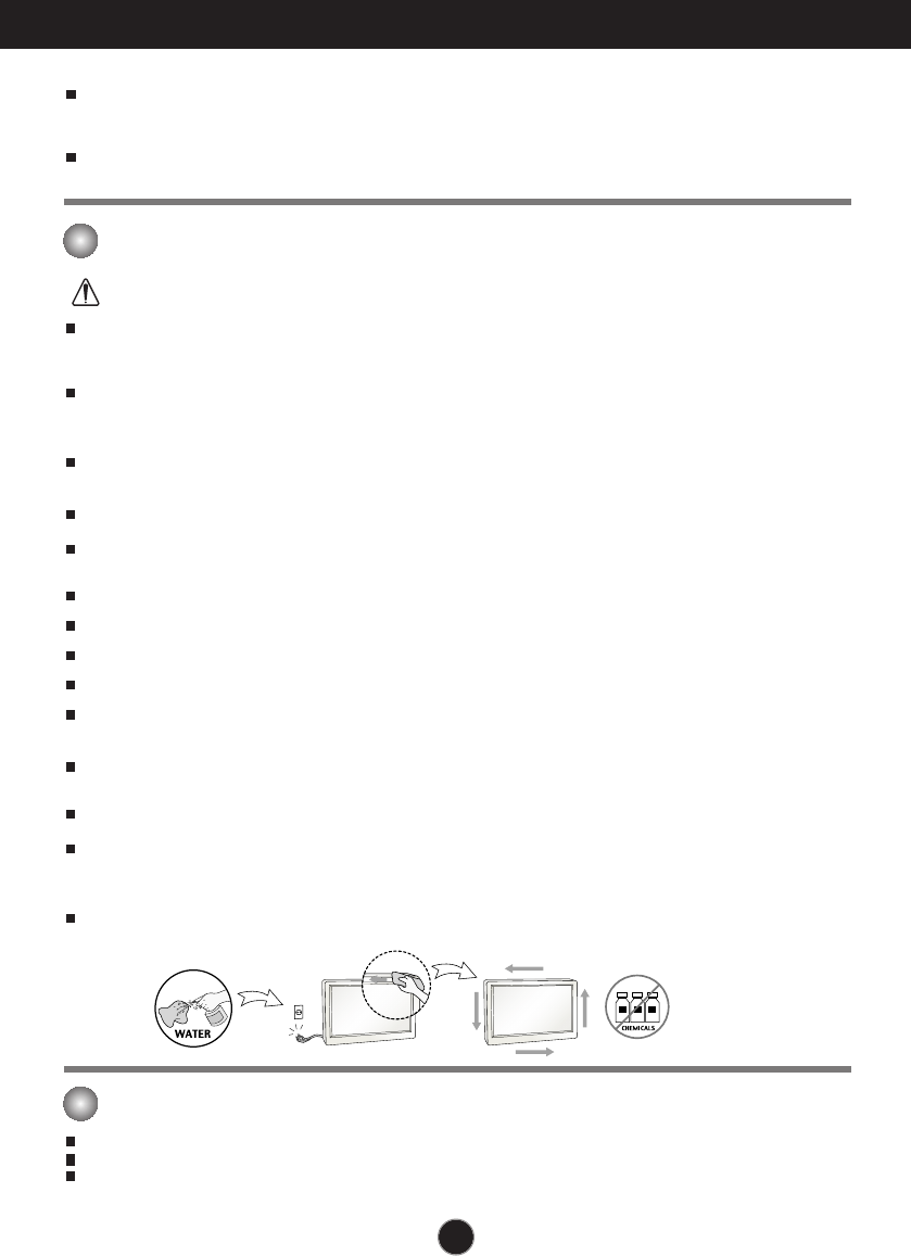
When cleaning the product, unplug the power cord and scrub gently with a soft cloth to prevent
scratching. Do not clean with a wet cloth. Or spray water or other liquids directly onto the product.
An electric shock may occur. (Do not use chemicals such as benzene, paint thinners or alcohol)
Keep the product away from water.
- Fire or electric shock accident can occur.
Avoid high temperatures and humidity.
Do not put or store flammable substances near the product.
- There is a danger of explosion or fire.
Keep the product clean at all times.
Take a comfortable and natural position when working with a product to relax the muscles.
Take a regular break when working with a product for a long time.
Do not press on the panel with a hand or sharp object such as nail, pencil or pen, or make a scratch on it.
Keep proper distance from the product and rest from time-to-time.
- Your vision may be impaired if you look at the product too closely or fpr too long.
Set the appropriate resolution by referring to the User’s Guide.
- Your vision can be impaired.
Keep small accessories out of the reach of children.
Leaving a fixed image on the screen for a long time may cause damage to the screen and cause image
burn-in. Make sure to use a screen saver on the product. Burn-in and related problems are not covered
by the warranty on this product.
Spray water onto a soft cloth 2 to 4 times, and use it to clean the front frame;wipe in one direction only.
Too much moisture may cause staining.
The fluorescent lamp used in this product contains a small amount of mercury.
Do not dispose of this product with general household waste.
Disposal of this product must be carried out in accordance to the regulations of your local authority.
Make sure the panel faces forward and hold it with both hands to move.
- If you drop the product, the damaged product can cause electric shock or fire. Contact an authorized the
service center for repair.
Do not place the product face down.
- This may damage the TFT-LCD screen.
On Disposal (Only , Hg lamp used LCD Monitor)
A4A4
Connecting the Display
Important
This illustration depicts the general model of connection. Your monitor may differ from
the items shown in the picture.
Do not carry the product upside down holding only the stand base. The product may
fall and get damaged or injure your foot.
Before setting up the monitor, ensure that the power to the monitor, the
computer system, and other attached devices is turned off.
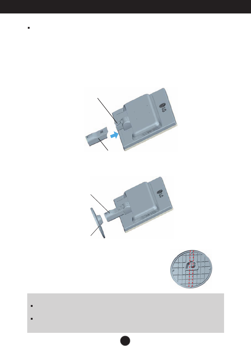
Connecting the stand
1.Place the monitor with its front facing downward on a soft cloth.
2.Assemble the Stand Body into the product in the correct direction as shown in the picture.
Make sure you push it until you hear it “click”.
3.Assemble the Stand Base(Front, Rear) into the Stand Body in the correct direction.
4.Tie down the base lock to perpendicularity direction.
5.Once assembled take the monitor up carefully and face
the front side.
Stand Body
Stand Base
Stand Body
Hinge Body
A5A5
Connecting the Display
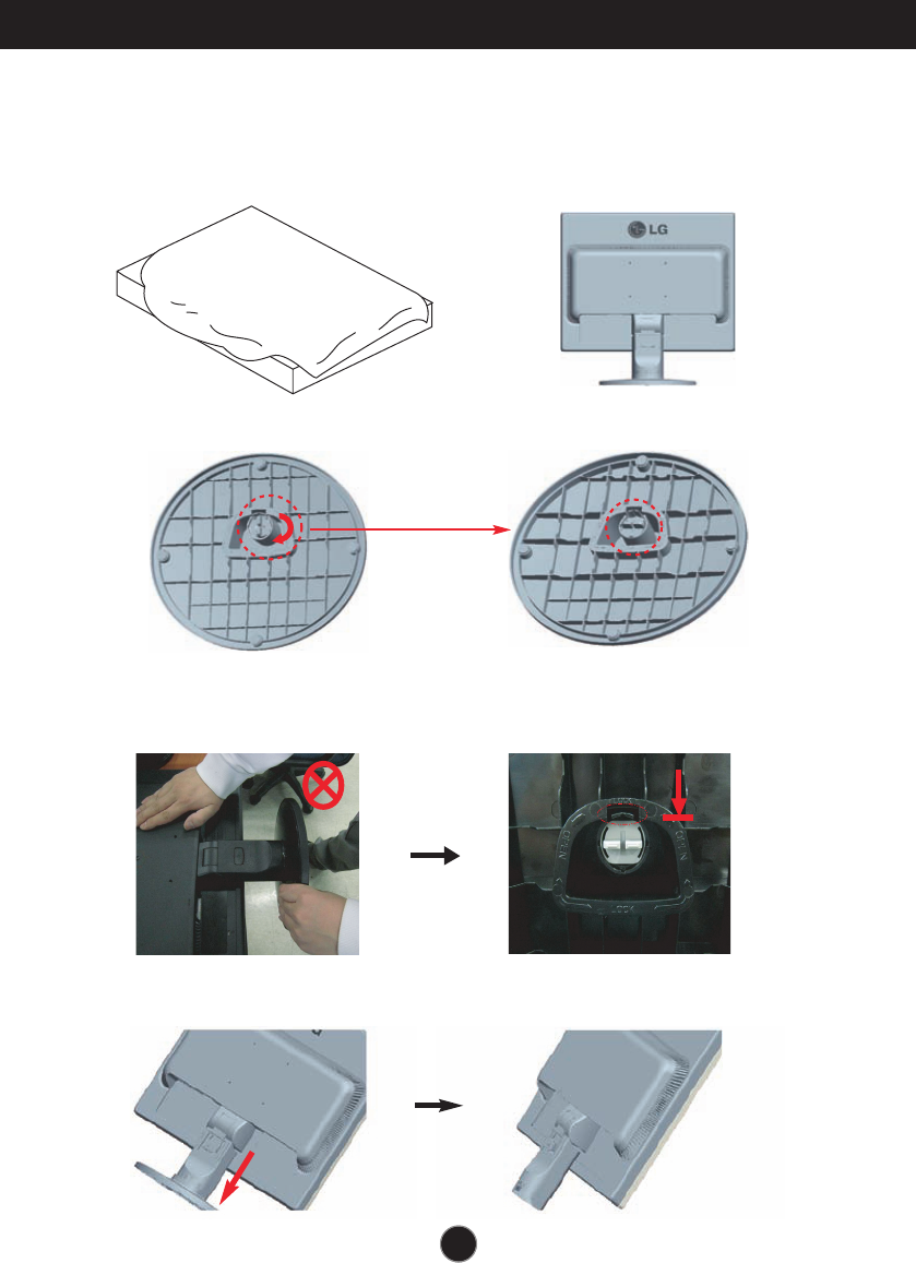
Disassembling the stand
1. Put a cushion or soft cloth on aflat
surface.
3. Change your lock on the product as it follows and turn it in the arrow direction.
2. Place the monitor face Down on the
cushion or soft cloth.
If you can't release the stand base even the locking knob is at a release
position, Please push the indicated knob down and retry it.
4.
Pull out the Stand to remove.
A6A6
Connecting the Display
Before setting up the monitor, ensure that the power to the monitor, the
computer system, and other attached devices is turned off.
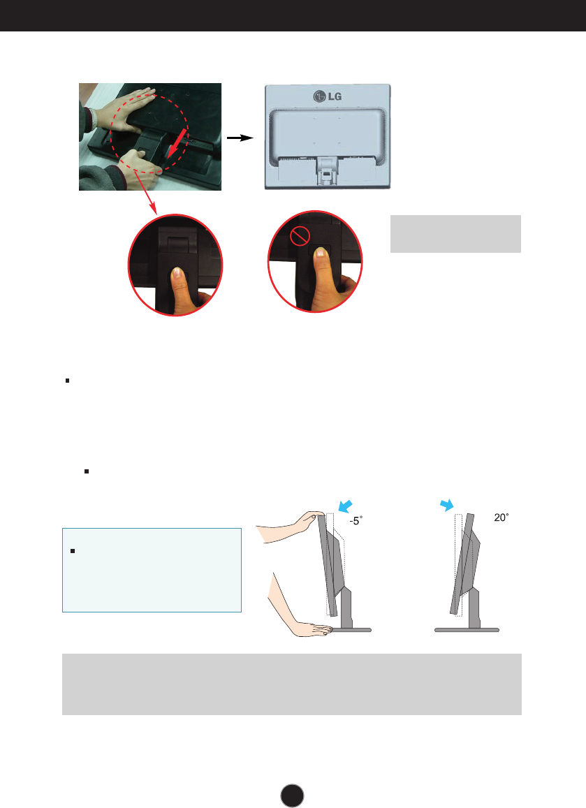
Positioning your display
1. Adjust the position of the panel in various ways for maximum comfort.
Tilt Range : -5˚~20˚
Ergonomic
It is recommended that in order to maintain an ergonomic and comfortable viewing
position, the forward tilt angle of the monitor should not exceed 5 degrees.
5.
Pushing the PUSH button, Take the stand base from stand body.
Good Position Bad Position
Warning:
You can hurt your finger.
When adjusting the angle of the
screen, do not put your finger(s)
in between the head of the
monitor and the stand body. You
can hurt your finger(s).
A7
Connecting the Display
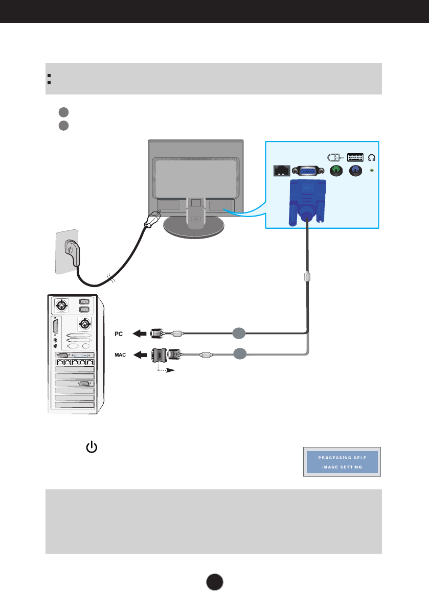
Using the Computer
2. Press button on the front switch panel to turn the
power on. When monitor power is turned on, the
'Self Image Setting Function' is executed automatically.
D-sub
X-PORT
B
A
Wall-outlet type
Analog signal
A
B
Mac adapter (This item must be purchased separately.)
For Apple Macintosh use, a separate plug adapter is
needed to change the 15 pin high density (3 row) D-sub
VGA connector on the supplied cable to a 15 pin 2 row
connector.
NOTE
‘ Self Image Setting Function’? This function provides the user with optimal display settings.When the user
connects the monitor for the first time, this function automatically adjusts the display to optimal settings for individual
input signals.
‘AUTO/SET’ Function? When you encounter problems such as blurry screen, blurred letters, screen flicker or tilted
screen while using the device or after changing screen resolution, press the AUTO/SET function button to improve
resolution.
NOTE
This is a simplified representation of the rear view.
This rear view represents a general model; your display may differ from the view as shown.
1. Connect D-sub(RGB Analog) Cable (PC)
Connect D-sub(RGB Analog) Cable (Mac)
A8
D-sub
X-PORT
Wall-outlet type
Analog signal
(Make sure to connect X550
port,not LAN port of PC)
Up to 5 ports are supported per X550 PCI Card.
Up to 5 ports can be connected if necessary.
(These items are not included for all models.)
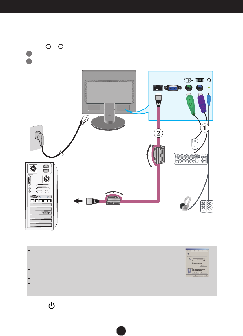
Using the Monitor
1. Make sure to turn off the computer and product. Connect the cable as below sketch map
form to .
12
1
2
Connect peripheral devices
Connect LAN Cable (X550 port)
Connecting the Display
Keyboard/Mouse Input
LAN cable should be
connected before boo-
ting PC.(This item must
be purchased separately.)
Headphone/Earphone Input
Automatically mutes the
speaker volume when the
headphones are plugged in.
When you use the monitor speaker via the X-PORT, turn the PC volume up to the highest
level and adjust the monitor volume.
It is recommended to use a PS/2-type keyboard/mouse.
To use the monitor keyboard/mouse properly, it must be connected to the PC.
Applications that require other than 16 bit color quality and the set resolution are not supported.
‘AUTO/SET’ Function? When you encounter problems such as blurry screen, blurred letters, screen flicker or titled
screen while using the device or after changing screen resolution, press the AUTO/SET function button to improve
resolution.
2. Press button on the front switch panel to turn the power on.
X550 port
A9
NOTE
Connecting the Display
Do not connect any kind of network devices.
Both connections
should be same
colors.
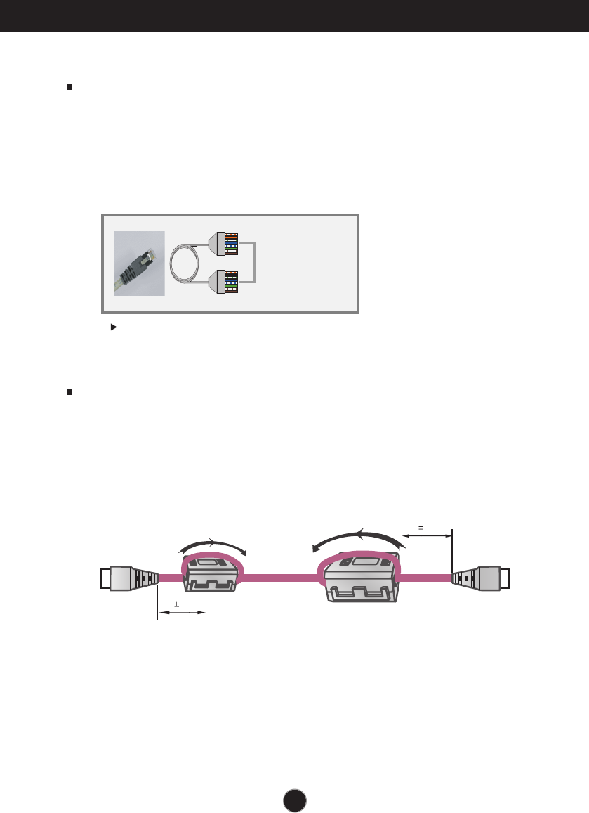
Core
The ferrite core can be used to reduce electromagnetic waves when connecting a
LAN cable.
As shown in the image below,fit the ferrite core to the LAN cable.
The ferrite core needs to be separated from the mold by 5 centimeters.
You can purchase SFTP(recommend : 6m,max : 10m)LAN cables and cores
through LG additionally.
For compliance with the FCC’s emissions requirements,the user shall use the
Ethernet cable with the split ferrite core on both ends.
LAN Cable
-For the LAN cable,it is recommended to use SFTP(recommend : 6m,max : 10m)
provided by LG.
Image quality and some functionality may be degraded if a different LAN cable is
used.
-To achieve good image quality,avoid using UTP and STP cables.
-You must use a direct LAN cable,not a crossover one.
50 10mm
50 10mm
A10
Connecting to a X550 port using a LAN cable.
Connecting the Display
Notice
Turning the power off while booting the PC may damage the product.
Turning the power off while booting the PC may cause it to operate incorrectly.
If the mouse is connected using a USB device and is not detected, disconnect and
connect it again.
If you reconnect a peripheral device such as a keyboard, mouse or LAN cable while
the PC is in operation, the device may not work properly.
Make sure that the power is turned off when disconnecting/connecting a peripheral
device.
Making both ends of LAN cable to across the coil two times before connect to
network monitor and PC.
PC spec :
The host PC operating system can be Windows Server 2003 R2 SP2(Standard or
Enterprise Edition, 32-bit).
Notice
- To achieve the best PC performance, up to six users are recommended for one PC.
If there are seven or more users, performance may be degraded depending on the
environment and the PC’s specifications.
- Check if the PC supports Windows Server 2003 before purchasing it.
A host PC should have the following specifications:
1. Minimum
- CPU : Dual core processor at 3.0 GHz or higher
(i.e. : Intel Core 2 Duo or AMD Athlon X2)
- RAM : 2 GB of system memory or higher
2. Recommend
- CPU : Quad core processor at 2.66 GHz or higher
(i.e. Intel Core 2 Quad or AMD Phenom X4)
- RAM : 4 GB of system memory
3. Internet access speed may be different depending on the network environment.
Restrictions :
Using this network monitor for the following purposes may cause screen disruption
or slower PC operation.
1. Video / Moving picture
2. Games
Color setting:
Image quality may vary depending on the X550 card, so it is recommended to
execute “White Balance” when using the product as a network monitor after
connecting a LAN cable for the first time.
Refer to A18 for more information on White Balance.
If you use the monitor with a X-PORT input, image quality and resolution may be poorer
than with a D-sub input.
( Only 16 bit color is supported for X-PORT input.)
A11
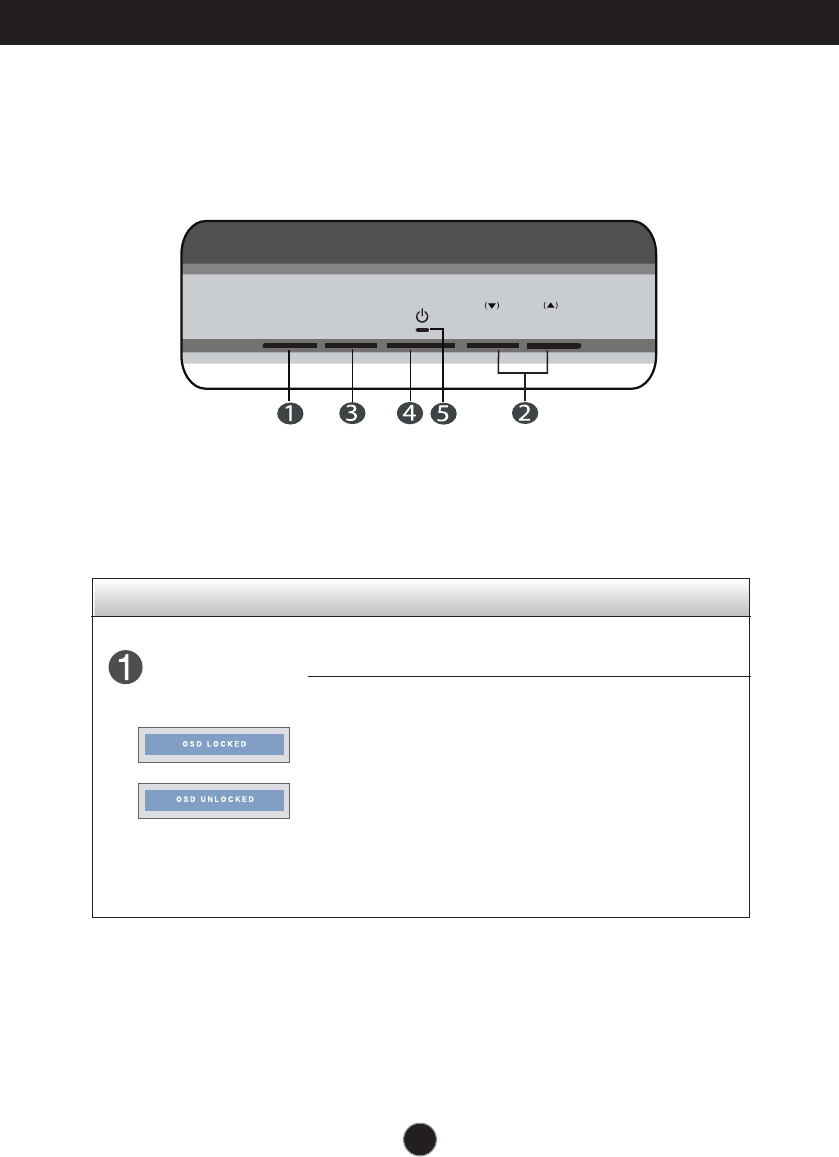
Control Function
Control Panel Functions
MENU Button
Use this button to enter or exit from the On Screen Display.
OSD LOCKED/UNLOCKED
This function allows you to lock the current control settings, so
that these settings are not inadvertently changed. To lock the
OSD settings, press and hold the MENU button for several
seconds. The message "OSD LOCKED" appears.
You can unlock the OSD settings at any time by
pushing the MENU button for several seconds. The
message "OSD UNLOCKED" appears.
Front Panel Controls
AUTO/SET VOLUMEMENU SOURCE
A12
Control Panel Functions
Control Function
This Indicator lights up blue when the display
operates normally(On Mode). If the display is in Sleep
Mode (Energy Saving), this indicator color changes
to flicker.
Use this button to turn the display on or off.
Power Button
Power Indicator
Use this button to enter a selection in the On Screen
Display.
AUTO/SET
Button
AUTO IMAGE ADJUSTMENT
When adjusting your display settings, always press
the AUTO/SET button before entering the On Screen
Display(OSD). This will automatically adjust your
display image to the ideal settings for the current
screen resolution size (display mode).
The best display mode is
17 inches : 1280 x 1024(D-sub) / 1024 x 768 (X-PORT)
19 inches : 1280 x 1024(D-sub) / 1024 x 768 (X-PORT)
SOURCE
VOLUME
Use these buttons to select or adjust functions in the
On Screen Display.
Use this button to make either D-Sub or X-PORT
connector active. This feature is used when two
input sources are connected to the display.
Use these buttons to select or adjust functions in the On
Screen Display.
• X-PORT : When X-PORT signal is active,Use button
to decrease or increase the speaker volume on
X-PORT input.
•D-sub : This menu is not available.
THIS MENU IS NOT AVAILABLE
A13
On Screen Display (OSD) Control Adjustment
Screen Adjustment
Making adjustments to the image size, position and operating parameters of
the display is quick and easy with the On Screen Display Control system.
A short example is given below to familiarize you with the use of the controls.
The following section is an outline of the available adjustments and selections
you can make using the OSD.
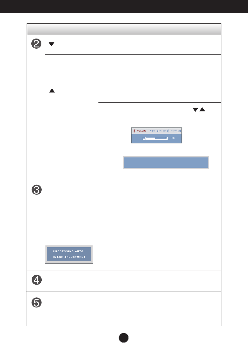
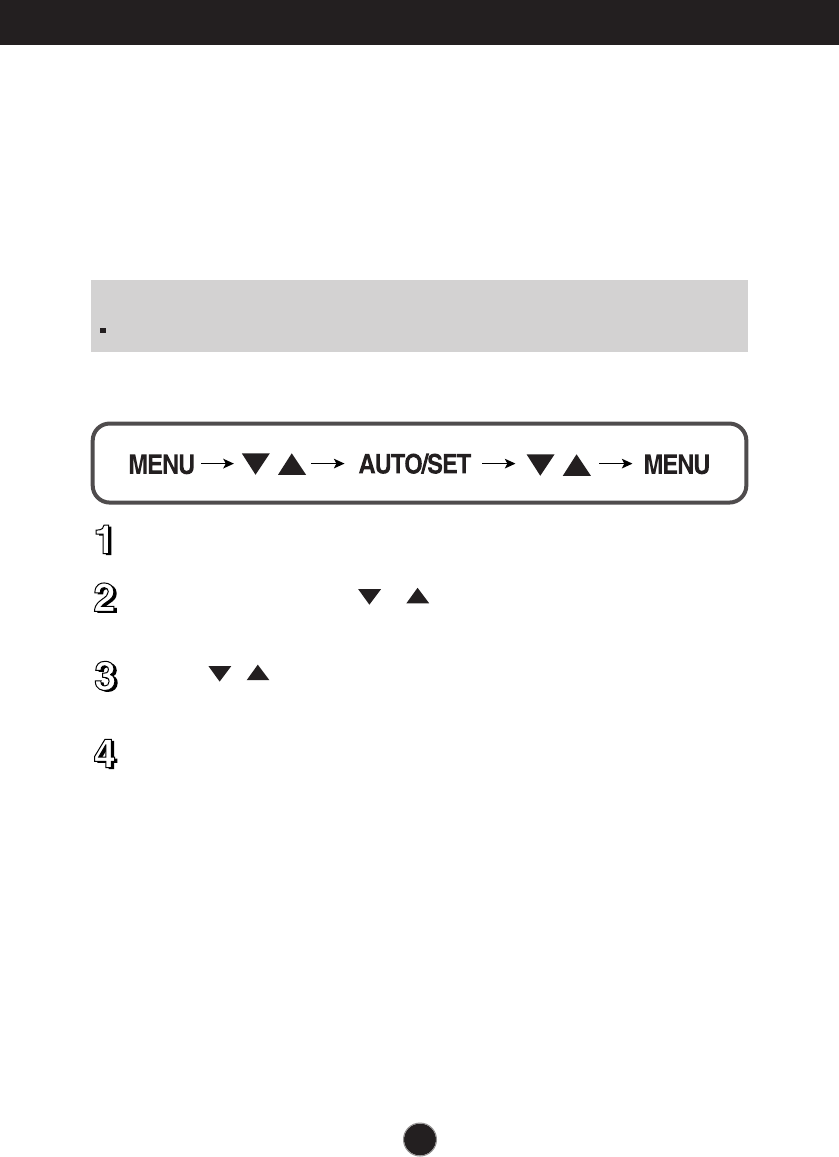
To make adjustments in the On Screen Display, follow these steps:
Press the MENU Button, then the main menu of the OSD appears.
To access a control, use the or Buttons. When the icon you want
becomes highlighted, press the AUTO/SET Button.
Use the / Buttons to adjust the image to the desired level. Use the
AUTO/SET Button to select other sub-menu items.
Push the MENU Button once to return to the main menu to select another
function. Push the MENU Button twice to exit from the OSD.
NOTE
Allow the display to stabilize for at least 30 minutes before making image adjustments.
A14
On Screen Display(OSD) Selection and Adjustment
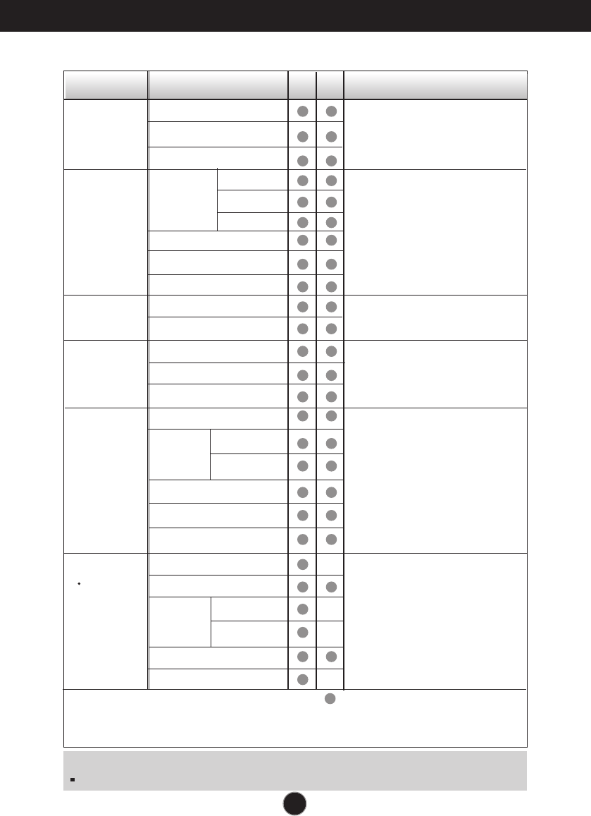
The following table indicates all the On Screen Display control,
adjustment, and setting menus.
NOTE
The order of icons may differ depending on the model (A14~A19).
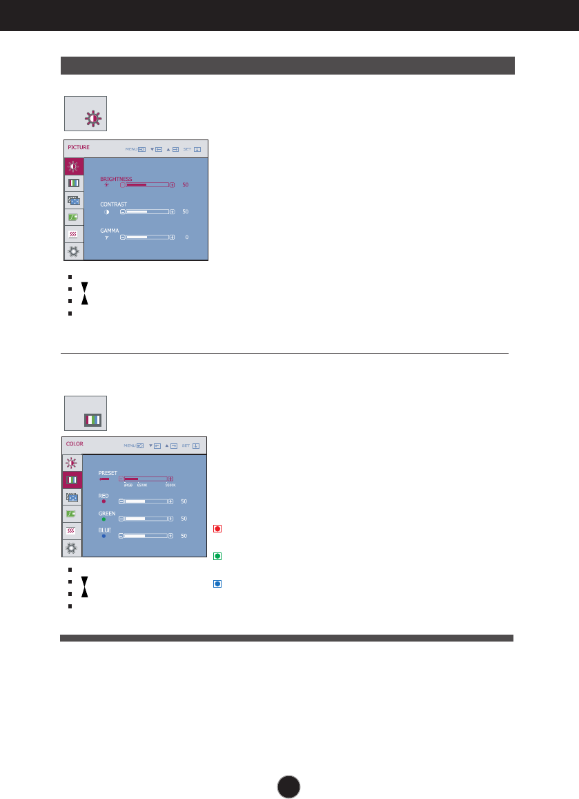
To adjust the brightness,
contrast and gamma of the
screen
PICTURE
COLOR
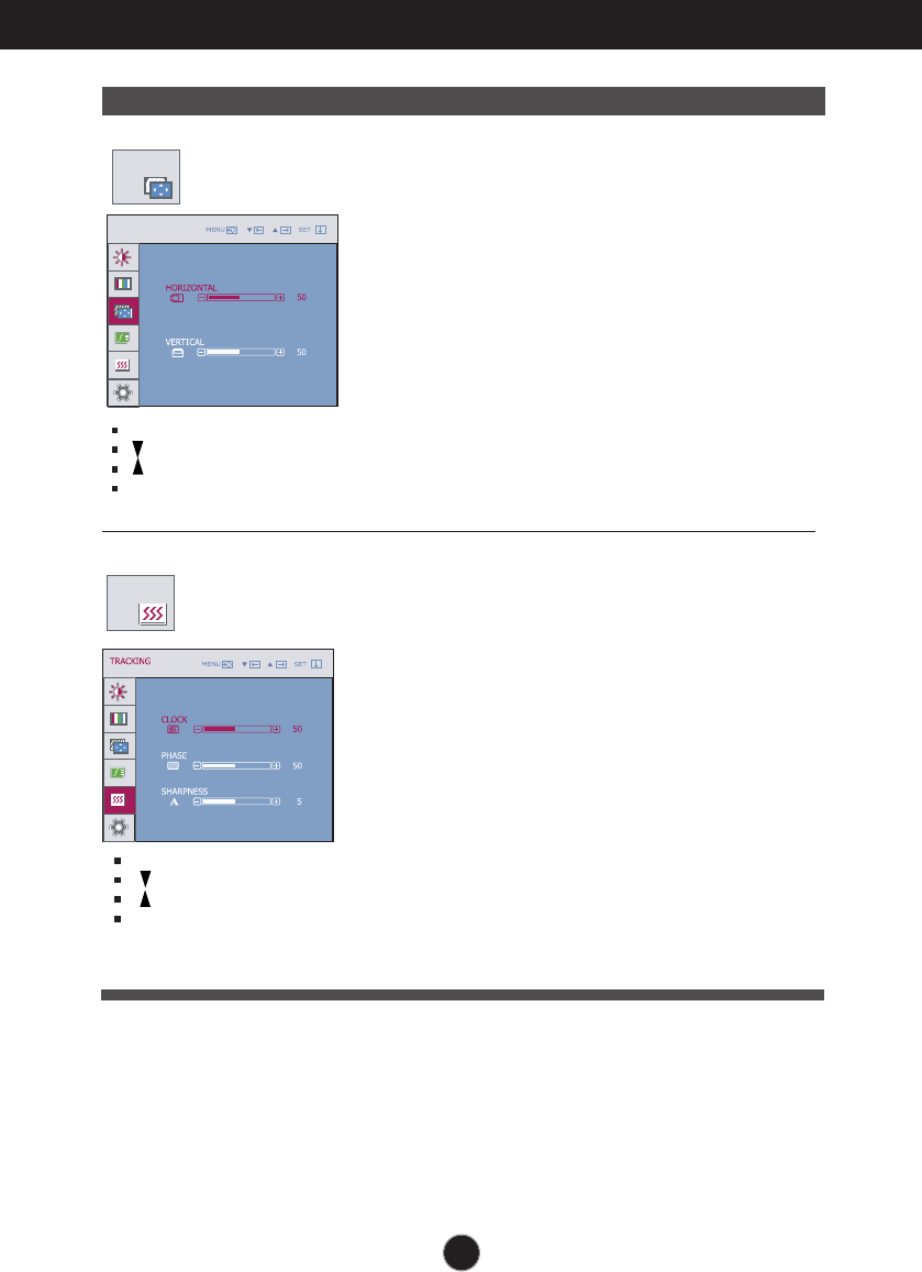
POSITION
TRACKING
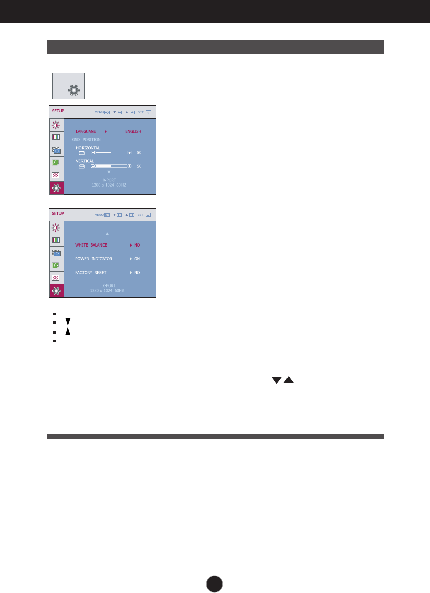
SETUP
Main menu Sub-menu A X Reference
PRESET
RED
GREEN
BLUE
To adjust the position of the
screen
To customize the color of
the screen
To customize the screen
status for a user's operating
environment
To improve the clarity and
stability of the screen
BRIGHTNESS
CONTRAST
GAMMA
HORIZONTAL
VERTICAL
CLOCK
PHASE
SHARPNESS
WHITE BALANCE
POWER INDICATOR
FACTORY RESET
LANGUAGE
OSD
HORIZONTAL
POSITION VERTICAL
sRGB
6500K
9300K
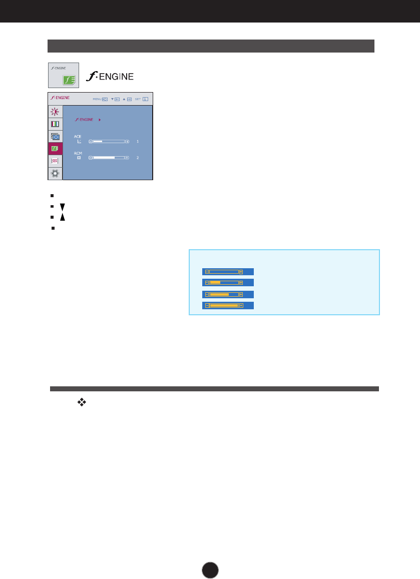
To select or customize
desired image settings
FLATRON
F ENGINE
MOVIE
INTERNET
NORMAL
DEMO
ACE
RCM
USER
: Adjustable
A : D-SUB Input
X : X-PORT Input
A15
On Screen Display(OSD) Selection and Adjustment
NOTE
OSD (On Screen Display) menu languages on the monitor may differ from the manual.
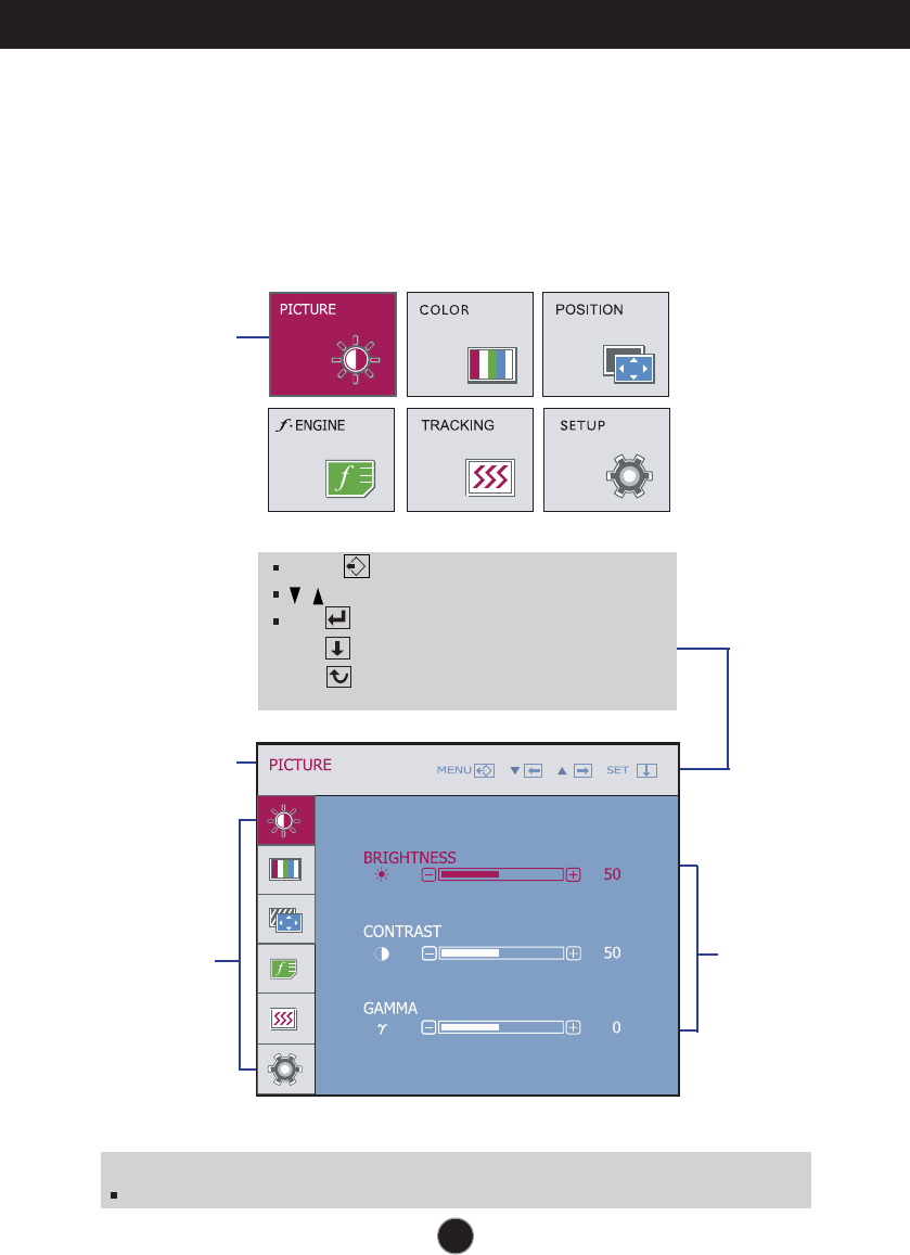
You were introduced to the procedure of selecting and adjusting an
item using the OSD system. Listed below are the icons, icon
names, and icon descriptions of the all items shown on the Menu.
Press the MENU Button, then the main menu of the OSD appears.
Menu Name
Menu Name
Main Menu
Button Tip
MENU : Exit
: Adjust (Decrease/Increase)
SET : Enter
: Select another sub-menu
: Restart to select sub-menu
Sub-menus
Icons
A16
On Screen Display(OSD) Selection and Adjustment
Main menu Sub menu Description
BRIGHTNESS
CONTRAST
GAMMA
To adjust the brightness of the screen.
To adjust the contrast of the screen.
Set your own gamma value. : -50/0/50
On the monitor, high gamma values
display whitish images and low gamma
values display blackish images.
PICTURE
PRESET
RED
GREEN
BLUE
• sRGB: Set the screen color to fit the
SRGB standard color
specification.
• 6500K: Slightly reddish white.
• 9300K: Slightly bluish white.
Set your own red color levels.
Set your own green color levels.
Set your own blue color levels.
COLOR
PICTURE
COLOR
MENU : Exit
: Decrease
: Increase
SET : Select another sub-menu
MENU : Exit
: Decrease
: Increase
SET : Select another sub-menu
A17
On Screen Display(OSD) Selection and Adjustment
MENU : Exit
: Decrease
: Increase
SET : Select another
sub-menu
Main menu Sub menu Description
CLOCK
PHASE
SHARPNESS
To minimize any vertical bars or stripes
visible on the screen background.
The horizontal screen size will also
change.
To adjust the focus of the display.
This item allows you to remove any
horizontal noise and clear or sharpen
the image of characters.
To adjust the clearness of the screen.
TRACKING
TRACKING
POSITION
POSITION
MENU : Exit
: Decrease
: Increase
SET : Select another sub-menu
HORIZONTAL
VERTICAL
To move image left and right.
To move image up and down.
POSITION
A18
On Screen Display(OSD) Selection and Adjustment
SETUP
SETUP
MENU : Exit
: Adjust
: Adjust
SET : Select another
sub-menu
If this does not improve the screen image, restore the factory default settings.
If necessary, perform the white balance function again. This function will be enabled only
when the input signal is a D-sub or X-PORT input signal.
To choose the language in which the
control names are displayed.
To adjust position of the OSD window
on the screen.
LANGUAGE
OSD
POSITION
WHITE
BALANCE
FACTORY
RESET
If the output of the video card is different
from the required specifications, the color
level may deteriorate due to video signal
distortion. Using this function, the signal
level is adjusted to fit into the standard
output level of the video card in order to
provide the optimal image.
Activate this function when white and
black colors are present in the screen.
POWER
INDICATOR
Restore all factory default settings except
"LANGUAGE" .
Press the , buttons to reset immediately.
Use this function to set the power
indicator on the front side of the monitor
to ON or OFF.
If you set OFF, it will go off.
If you set ON at any time, the power
indicator will automatically be turned on.
Main menu Sub menu Description
A19
On Screen Display(OSD) Selection and Adjustment
Main menu Sub menu Description
MOVIE
INTERNET
NORMAL
DEMO
USER
INTERNET
: For text images (Word processing etc.)
MOVIE
: For animation images in videos or movies
This is under normal operating conditions.
This is just for advertising to customer in the
shops. It’s setting is same with Movie mode and
screen is divided by half.
This feature lets you easily select the best desired
image condition optimized to the environment
(ambient illumination, image types etc).
User
You can manually adjust ACE or RCM.
You can save or restore the adjusted value even
when using a different environment.
...
ACE
(Adaptive Clarity Enhancer)
:
Selects the clarity mode.
...
RCM(Real Color Management):
Selects the color mode.
Not applied
Green enhance
Flesh tone
Color Enhance
0
1
2
3
USER
MENU : Exit
: Decrease
: Increase
SET :
Select another
sub-menu
The INTERNET and NORMAL features become enabled for X-PORT input.
A20
Troubleshooting
No image appears
Check the following before calling for service.
No image appears
Do you see a "OSD LOCKED" message on the screen?
• You can secure the current control settings,
so that they cannot be inadvertently changed.
You can unlock the OSD controls at any time
by pushing the MENU button for several
seconds: the message
“OSD UNLOCKED”will appear.
●
Do you see “OSD
LOCKED” when you
push MENU button?
●Is the power cord of the
display connected?
●Is the power indicator
light on?
●Is the power indicator
flickering?
●Do you see an "OUT OF
RANGE" message on
the screen?
●Do you see a "CHECK
SIGNAL CABLE"
message on the
screen?
•
Check and see if the power cord is connected
properly to the power outlet.
•
Press the Power button.
•
If the display is in power saving mode, try moving
the mouse or pressing any key on the keyboard to
bring up the screen.
• Try to turn on the PC
.
•
This message appears when the signal from the
PC (video card) is out of horizontal or vertical
frequency range of the display. See the
'Specifications' section of this manual and
configure your display again.
•
This message appears when the signal cable
between your PC and your display is not
connected. Check the signal cable and try again.
A21A21
Troubleshooting
Display image is incorrect
●Display Position is
incorrect.
●On the screen
background, vertical
bars or stripes are
visible.
●Any horizontal noise
appearing in any
image or characters
are not clearly
portrayed.
•
Press the AUTO/SET button to automatically
adjust your display image to the ideal setting.
If the results are unsatisfactory, adjust the image
position using the H position and V position icon
in the on screen display.
•
Press the AUTO/SET button to automatically
adjust your display image to the ideal setting.
If the results are unsatisfactory, decrease the
vertical bars or stripes using the CLOCK icon in
the on screen display.
•
Press the AUTO/SET button to automatically
adjust your display image to the ideal setting.
If the results are unsatisfactory, decrease the
horizontal bars using the PHASE icon in the on
screen display.
•
Check Control Panel --> Display --> Settings
and adjust the display to the recommended
resolution or adjust the display image to the ideal
setting. Set the color setting higher than 24 bits
(true color).(Only for D-SUB input)
Important
Check Control Panel --> Display --> Settings and see if the frequency or the
resolution were changed. If yes, readjust the video card to the recommend
resolution.(Only for D-SUB input)
The setting method can differ by computer and O/S (Operation System),
and resolution mentioned above may not be supported by the video card
performance. In this case, please ask to the computer or the video card
manufacturer.
(Only for D-SUB input)
A22A22
Troubleshooting
Display image is incorrect
●The screen color is
mono or abnormal.
●The screen blinks.
•
Check if the signal cable is properly connected
and use a screwdriver to fasten if necessary.
•
Make sure the video card is properly inserted in
the slot.
•
Set the color setting higher than 24 bits (true color)
at Control Panel - Settings.
(X-PORT support only 16bits color)
- “White Balance” is performed on black/white
pattern.
- Check if the screen is set to normal mode.
•
Check if the screen is set to interlace mode and if
yes, change it to the recommend resolution.
- Check if the screen is set to normal mode.
A23A23
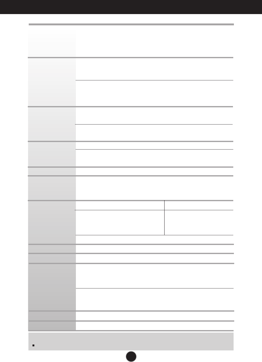
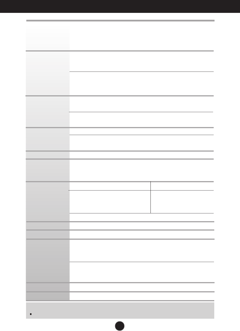
Specifications N1742L/N1742LP
Display
Sync Input
Video Input
Resolution
Plug&Play
Power
Consumption
Dimensions
& Weight
Tilt Range
Power Input
Environmental
Conditions
Stand Base
Power cord
TFT (Thin Film Transistor) LCD (Liquid Crystal Display) Panel,
Anti-Glare coating
17 inches visible diagonal (43.2 cm)
0.264 mm pixel pitch
Horizontal Freq. 30 - 66 kHz (Automatic)
D-SUB Vertical Freq. 57 - 63 Hz (Automatic)
D-SUB support 60Hz only(except Dos mode)
1440 x 900 (60Hz) 1280 x 720 (60Hz)
X-PORT 1280 x 1024 (60Hz) 800 x 600 (72Hz)
1024 x 768 (60Hz)
D-SUB Signal Input 15 pin D-Sub Connector
Input Form RGB Analog (0.7 Vp-p/ 75 ohm)
X-PORT Signal Input X-PORT Connector
Input Form X-PORT Signal
Max VESA 1280 x 1024 @60 Hz
Recommend D-SUB VESA 1280 x 1024 @60 Hz
X-PORT VESA 1024 x 768 @60 Hz
DDC 2B
(Only for D-SUB input)
On Mode : 32 W(Typ.)
Sleep Mode ≤1 W
Off Mode ≤1 W
With Stand Without Stand
Width 36.96 cm / 14.55 inches 36.96 cm / 14.55 inches
Height 39.13 cm / 15.41 inches 31.51 cm / 12.41 inches
Depth 18.48 cm / 7.28 inches 5.90 cm / 2.32 inches
Net 3.1 kg (6.89 lbs)
Tilt -5˚~ 20˚
AC 100-240V~ 50/60Hz 0.8A
Operating Conditions
Temperature 10˚C to 35 ˚C
Humidity 10 % to 80 % non-Condensing
Storage Conditions
Temperature -20˚C to 60 ˚C
Humidity 5 % to 90 % non-Condensing
Attached ( ), Detached ( O )
Wall-outlet type
NOTE
Information in this document is subject to change without notice.
A24
Specifications N1942L
Display
Sync Input
Video Input
Resolution
Plug&Play
Power
Consumption
Dimensions
& Weight
Tilt Range
Power Input
Environmental
Conditions
Stand Base
Power cord
TFT (Thin Film Transistor) LCD (Liquid Crystal Display) Panel,
Anti-Glare coating
19 inches visible diagonal (48.2 cm)
0.294 mm pixel pitch
Horizontal Freq. 30 - 66 kHz (Automatic)
D-SUB Vertical Freq. 57 - 63 Hz (Automatic)
D-SUB support 60Hz only(except Dos mode)
1440 x 900 (60Hz) 1280 x 720 (60Hz)
X-PORT 1280 x 1024 (60Hz) 800 x 600 (72Hz)
1024 x 768 (60Hz)
D-SUB Signal Input 15 pin D-Sub Connector
Input Form RGB Analog (0.7 Vp-p/ 75 ohm)
X-PORT Signal Input X-PORT Connector
Input Form X-PORT Signal
Max VESA 1280 x 1024 @60 Hz
Recommend D-SUB VESA 1280 x 1024 @60 Hz
X-PORT VESA 1024 x 768 @60 Hz
DDC 2B
(Only for D-SUB input)
On Mode : 40 W(Max.)
Sleep Mode ≤1 W
Off Mode ≤1 W
With Stand Without Stand
Width 40.63 cm / 16.00 inches 40.63 cm / 16.00 inches
Height 41.97 cm / 16.52 inches 34.45 cm / 13.56 inches
Depth 18.48 cm / 7.28 inches 5.99 cm / 2.36 inches
Net 3.5 kg (7.78 lbs)
Tilt -5˚~ 20˚
AC 100-240V~ 50/60Hz 0.8A
Operating Conditions
Temperature 10˚C to 35 ˚C
Humidity 10 % to 80 % non-Condensing
Storage Conditions
Temperature -20˚C to 60 ˚C
Humidity 5 % to 90 % non-Condensing
Attached ( ), Detached ( O )
Wall-outlet type
NOTE
Information in this document is subject to change without notice.
A25
Specifications
D-SUB Preset Modes (Resolution)
Display Modes (Resolution) Horizontal Freq. (kHz) Vertical Freq. (Hz)
*Recommend Mode
Indicator
On Mode
Sleep Mode
Off Mode
Blue
Flicker
Off
LED Color
MODE
1
2
3
4
5
*6
31.469
31.468
31.469
37.879
48.363
63.981
70
70
60
60
60
60
640 x 350
720 x 400
640 x 480
800 x 600
1024 x 768
1280 x 1024
X-PORT Preset Modes (Resolution)
Display Modes (Resolution)
*Recommend Mode
1
*2
3
4
5
800 x 600(72Hz)
1024 x 768(60Hz)
1280 x 720(60Hz)
1280 x 1024(60Hz)
1440 x 900(60Hz)
A26
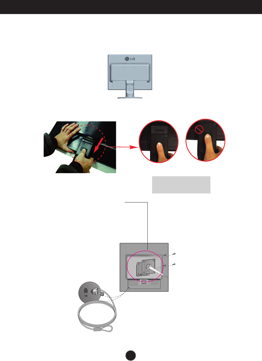
Installing the Wall mount plate
Wall mount plate(Separate purchase)
This is stand-type or wall mount type and is
connectable with Wall mount plate.
Please refer to the installation guide for more
details, which is provided when Wall mount
plate is purchased.LG recommends that wall
mounting be performed by a qualified
professional installer.
Kensington Security Slot
Connected to a locking cable that can be
purchased separately at most computer
stores.
This monitor satisfies the specifications of the Wall mount
plate or the interchange device.
1. Place the monitor with its front facing downward on a soft cloth.
2.Separate the stand by pushing the PUSH button.
3.
Install the Wall mount plate.
Warning:
You can hurt your finger.
Good Position Bad Position

Digitally yours