LG Electronics USA N1942LT LCD NETWORK MONITOR. User Manual Lx6WTG Q ENG
LG Electronics USA LCD NETWORK MONITOR. Lx6WTG Q ENG
Users Manual

Make sure to read the Important Precautions before using the product.
Keep the User's Guide(CD) in an accessible place for future reference.
See the label attached on the product and give the information to your
dealer when you ask for service.
N1742L
User’s Guide
N1942L
Network Monitor

A1
This unit has been engineered and manufactured to ensure your personal safety,
however improper use may result in potential electrical shock or fire hazards. In
order to allow the proper operation of all safeguards incorporated in this display,
observe the following basic rules for its installation, use, and servicing.
On Safety
Use only the power cord supplied with the unit. In case you use another power
cord, make sure that it is certified by the applicable national standards if not being
provided by the supplier. If the power cable is faulty in any way, please contact the
manufacturer or the nearest authorized repair service provider for a replacement.
The power supply cord is used as the main disconnection device. Ensure that the
socket-outlet is easily accessible after installation.
Operate the display only from a power source indicated in the specifications of
this manual or listed on the display. If you are not sure what type of power supply
you have in your home, consult with your dealer.
Overloaded AC outlets and extension cords are dangerous. So are frayed power
cords and broken plugs. They may result in a shock or fire hazard. Call your service
technician for replacement.
As long as this unit is connected to the AC wall outlet, it is not disconnected from
the AC power source even if you turn off this unit by SWITCH.
Do not Open the Display:
There are no user serviceable components inside.
There are Dangerous High Voltages inside, even when the power is OFF.
Contact your dealer if the display is not operating properly.
To Avoid Personal Injury :
Do not place the display on a sloping shelf unless properly secured.
Use only a stand recommended by the manufacturer.
Do not drop an object on or apply impact to the product. Do not throw any toys
or objects on the product screen.
It can cause injury to human, problem to product and damage the display.
To Prevent Fire or Hazards:
Always turn the display OFF if you leave the room for more than a short period
of time. Never leave the display ON when leaving the house.
Keep children from dropping or pushing objects into the display's cabinet
openings. Some internal parts carry hazardous voltages.
Do not add accessories that have not been designed for this display.
When the display is to be left unattended for an extended period of time, unplug
it from the wall outlet.
In the presence of thunder and lightning, never touch the power cord and signal
cable because it can be very dangerous. It can cause electric shock.
Important Precautions

A
Important Precautions
On Installation
Do not allow anything to rest upon or roll over the power cord, and do not place
the display where the power cord is subject to damage.
Do not use this display near water such as near a bathtub, washbowl, kitchen
sink, laundry tub, in a wet basement, or near a swimming pool.
Displays are provided with ventilation openings in the cabinet to allow the release
of heat generated during operation. If these openings are blocked, built-up heat
can cause failures which may result in a fire hazard. Therefore, NEVE :
lock the bottom ventilation slots by placing the display on a bed, sofa, rug, etc.
Place the display in a built-in enclosure unless proper ventilation is provided.
Cover the openings with cloth or other material.
Place the display near or over a radiator or heat source.
Do not rub or strike the Active atrix CD with anything hard as this may scratch,
mar, or damage the Active atrix CD permanently.
Do not press the CD screen with your finger for a long time as this may cause
some afterimages.
Some dot defects may appear as ed, reen or lue spots on the screen.
However, this will have no impact or effect on the display performance.
If possible, use the recommended resolution to obtain the best image uality for
your CD display. If used under any mode except the recommended resolution,
some scaled or processed images may appear on the screen. However, this is
characteristic of the fixed-resolution CD panel.
eaving a fixed image on the screen for a long time may cause damage to the
screen and cause image burn-in. ake sure to use a screen saver on the product.
urn-in and related problems are not covered by the warranty on this product.
Do not shock or scratch the front and sides of the screen with metallic objects.
Otherwise, it may cause damage to the screen.
ake sure the panel faces forward and hold it with both hands to move. If you
drop the product, the damaged product can cause electric shock or fire. Contact
an authorized the service center for repair.
Avoid high temperatures and humidity.
Important Precautions
A
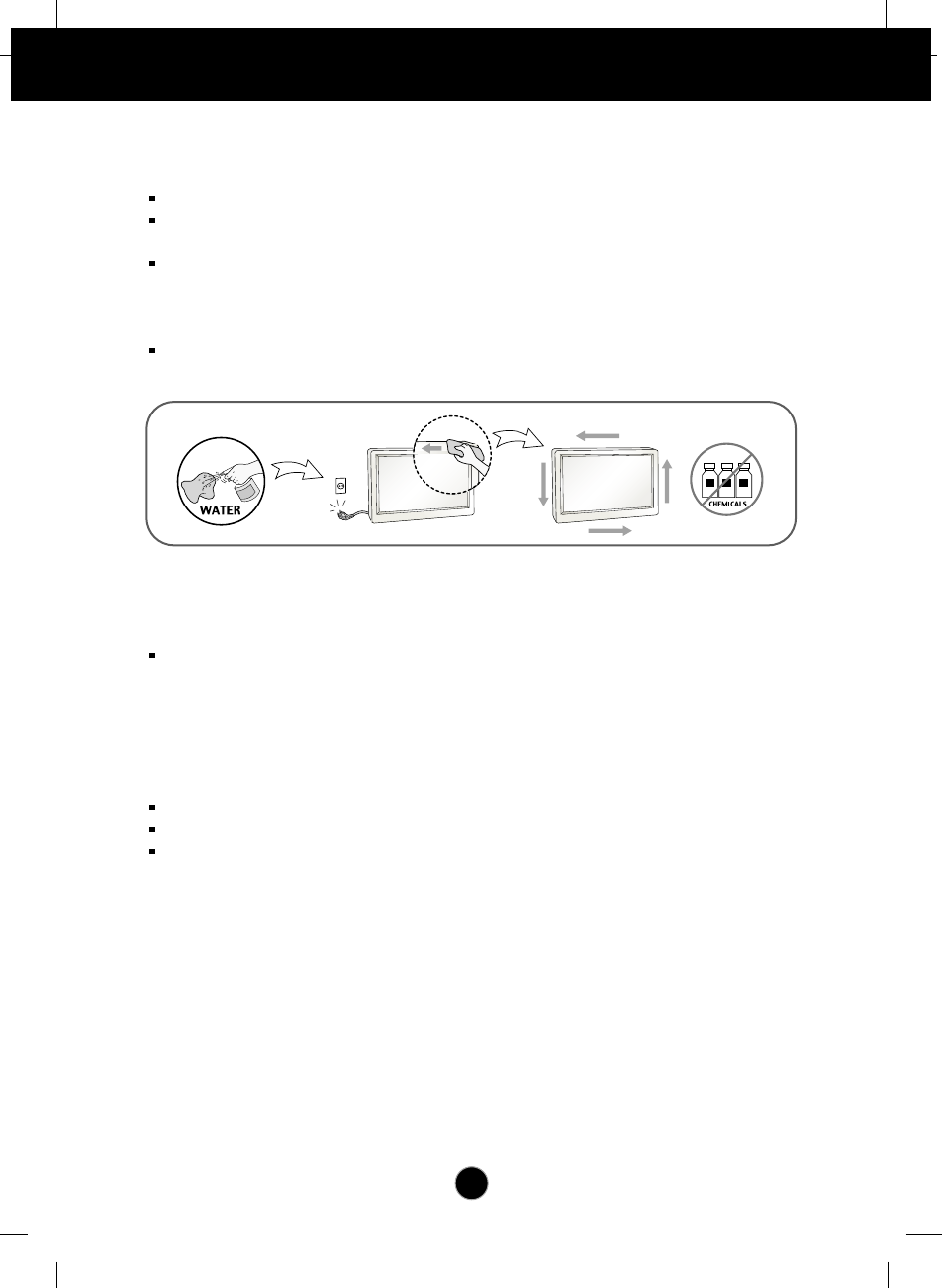
On Cleaning
Unplug the display before cleaning the face of the display screen.
Use a slightly damp not wet cloth. Do not use an aerosol directly on the display
screen because over-spraying may cause electrical shock.
When cleaning the product, unplug the power cord and scrub gently with a soft
ro retaw yarps ro htolc tew a htiw naelc ton oD .gnihctarcs tneverp ot htolc
other li uids directly onto the product. An electric shock may occur. Do not use
chemicals such as benzene, paint thinners or alcohol
Spray water onto a soft cloth to times, and use it to clean the front frame
wipe in one direction only. Too much moisture may cause staining.
On epacking
Do not throw away the carton and packing materials. They make an ideal
container in which to transport the unit. When shipping the unit to another
location, repack it in its original material.
On Disposal
The fluorescent lamp used in this product contains a small amount of mercury.
Do not dispose of this product with general household waste.
Disposal of this product must be carried out in accordance to the regulations of
your local authority.
A
Connecting the Display
Important
This illustration depicts the general model of connection. Your monitor may differ from
the items shown in the picture.
Do not carry the product upside down holding only the stand base. The product may
fall and get damaged or injure your foot.
Before setting up the monitor, ensure that the power to the monitor, the computer
system, and other attached devices is turned off.
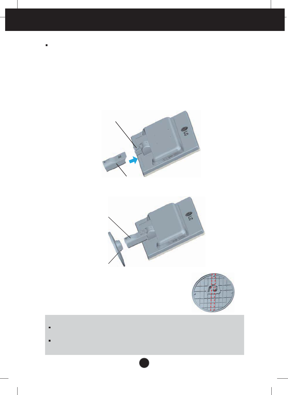
Connecting the stand
1.Place the monitor with its front facing downward on a soft cloth.
2.Assemble the Stand Body into the product in the correct direction as shown in the picture.
Make sure you push it until you hear it “click”.
3.Assemble the Stand Base(Front, Rear) into the Stand Body in the correct direction.
4.Tie down the base lock to perpendicularity direction.
5.Once assembled take the monitor up carefully and face
the front side
Stand Body
Stand Base
Stand Body
Hinge Body
A5
Connecting the Display
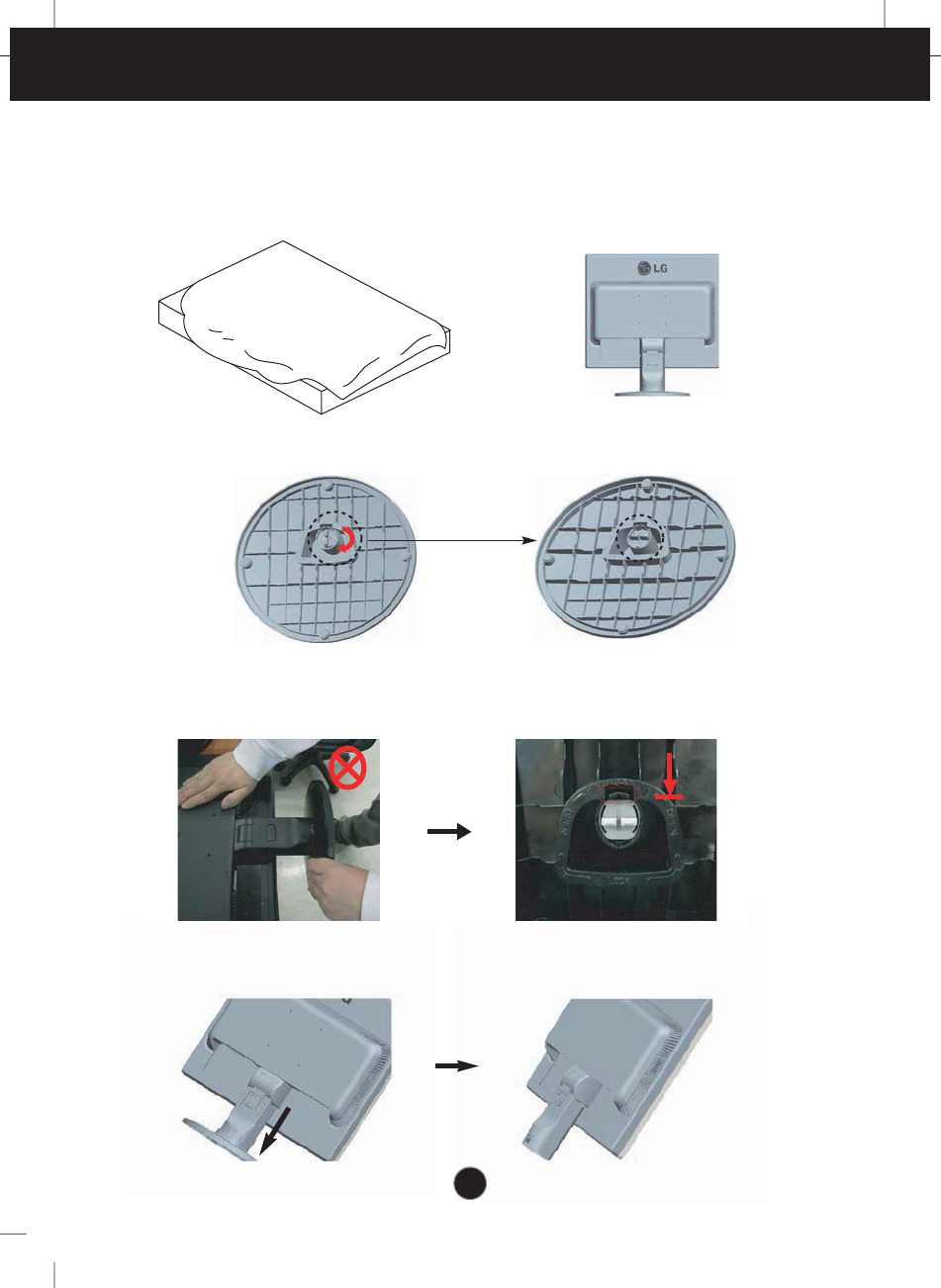
Disassembling the stand
1. Put a cushion or soft cloth on aflat
surface.
3. Change your lock on the product as it follows and turn it in the arrow direction.
2. Place the monitor face Down on
the cushion or soft cloth.
If you can't release the stand base even the locking knob is at a release
position, Please push the indicated knob down and retry it.
4.
Pull out the Stand to remove.
A
Connecting the Display
efore setting up the monitor, ensure that the power to the monitor, the computer
system, and other attached devices is turned off.
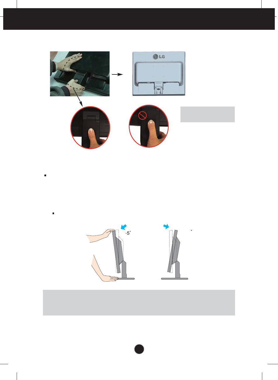
Positioning your display
1.Adjust the position of the panel in various ways for maximum comfort.
Tilt ange : -5˚~20˚
Ergonomic
It is recommended that in order to maintain an ergonomic and comfortable viewing
position, the forward tilt angle of the monitor should not exceed degrees.
.
Pushing the PUSH button, Take the stand base from stand body.
ood Position ad Position
Warning:
ou can hurt your finger.
A7
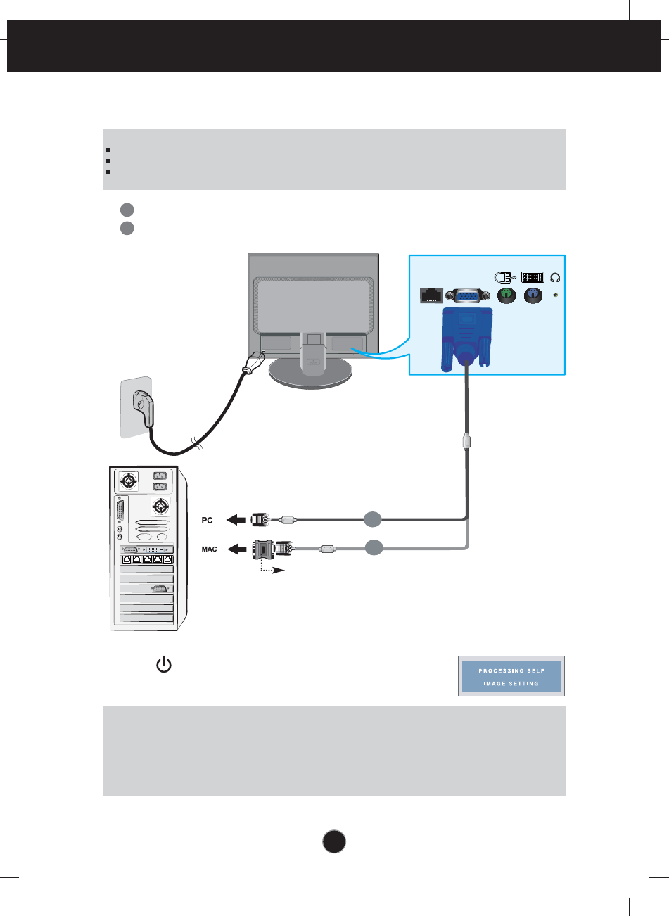
Connecting the Display
Using the Compute
Wall-outlet type
A
B
Connect Dsub Cable (PC)
Connect Dsub Cable (Mac)
Mac adapter
(This item must be purchased separately.)
Analog signal
D-sub
X-PORT
NOTE
This is a simplified representation of the rear view.
This rear view represents a general model; your display may differ from the view as shown.
User must use shielded signal interface cables (D-sub 15 pin cable, LAN cable) with ferrite cores to maintain standard
compliance for the product.
r
B
A
2. Press button on the front switch panel to turn the
power on. When monitor power is turned on, the
'Self Image Setting Function' is executed automatically.
NOTE
‘ Self Image Setting Function’? This function provides the user with optimal display settings.When the user
connects the monitor for the first time, this function automatically adjusts the display to optimal settings for individual
input signals.
‘AUTO/SET’ Function? When you encounter problems such as blurry screen, blurred letters, screen flicker or tilted
screen while using the device or after changing screen resolution, press the AUTO/SET function button to improve
resolution.
For Apple Macintosh use,a separate plug adapter is needed to change the 15
pin high density (3 row)D-sub VGA connector on the supplied cable to a 15 pin
2 row connector.
1.
A8
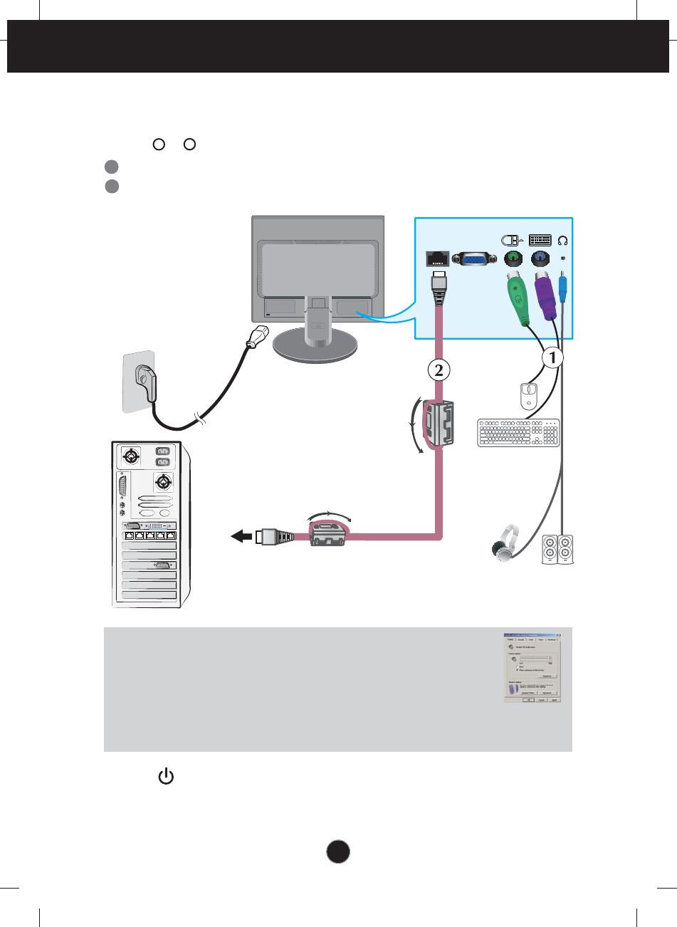
Connecting the Display
Using the Monitor
Wall-outlet type
2
Connect LAN Cable (X550 port)
■ When you use the monitor speaker via the X-PORT, turn the PC volume up to the highest
level and adjust the monitor volume.
■ It is recommended to use a PS/2-type keyboard/mouse.
To use the monitor keyboard/mouse properly, it must be connected to the PC.
■ Applications that require other than 16 bit color quality and the set resolution are not supported.
■ ‘AUTO/SET’ Function? When you encounter problems such as blurry screen, blurred letters, screen flicker or titled
screen while using the device or after changing screen resolution, press the AUTO/SET function button to improve
resolution.
Analog signal
D-sub
X-PORT
Headphone/Earphone Input
Automatically mutes the
speaker volume when the
headphones are plugged in.
X550 port
(Make sure to connect X550
port,not LAN port of PC)
Keyboard/Mouse Input
LAN cable should be
connected before boo-
ting PC.(This item must
be purchased separately.)
Up to 5 ports are supported per X550 PCI Card.
Up to 5 ports can be connected if necessary.
(This item must be purchased separately.)
1. Make sure to turn off the computer and product. Connect the cable as below sketch map
form to .
12
PC
1
Connect peripheral devices
2. Press button on the front switch panel to turn the power on.
A9
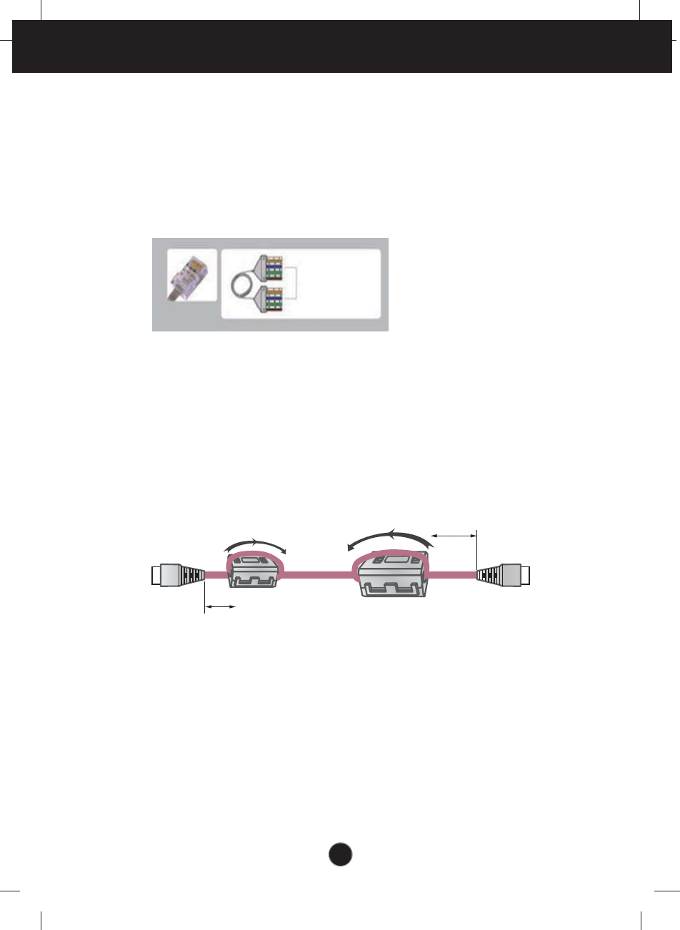
■ LAN Cable
Connecting the Dispaly
X Do not connect any kind of network devices.
- For the LAN cable, it is recommended to use a 6m SFTP provided by LG.
Image quality and some functionality may be degraded if a different LAN cable is
used.
- To achieve good image quality, avoid using UTP and STP cables.
- You must use a direct LAN cable, not a crossover one.
NOTE
The ferrite core can be used to reduce electromagnetic waves when connecting a
LAN cable.
As shown in the image below, fit the ferrite core to the LAN cable.
The ferrite core needs to be separated from the mold by 5 centimeters.
You can purchase SFTP 6m LAN cables and cores through LG additionally.
■ Core
PC
50±10
50±10
Both connections
should be same
colors.
For compliance with the FCC’s emissions requirements,the user shall use the
Ethernet cable with the split ferrite core on both ends.

A10
Connecting to a X550 port using a LAN cable.
Notice
Turning the power off while booting the PC may damage the product.
Turning the power off while booting the PC may cause it to operate incorrectly.
If the mouse is connected using a USB device and is not detected, disconnect and
connect it again.
PC spec :
The host PC operating system can be Windows Server 2003 R2 SP2(Standard or
Enterprise Edition, 32-bit).
Notice
- To achieve the best PC performance, up to six users are recommended for one PC.
If there are seven or more users, performance may be degraded depending on the
environment and the PC’s specifications.
- Check if the PC supports Windows Server 2003 before purchasing it.
A host PC should have the following specifications:
Using this network monitor for the following purposes may cause screen disruption
or slower PC operation.
1. Video / Moving picture
2. Games
Color setting:
Image quality may vary depending on the X550 card, so it is recommended to
execute “White Balance” when using the product as a network monitor after
connecting a LAN cable for the first time.
O
Refer to A18 for more information on White Balance.
If you use the monitor with a X-PORT input, image quality and resolution may be poorer
than with a D-sub input.
(
O
Only 16 bit color is supported for X-PORT input.)
Connecting the Dispaly
If you reconnect a peripheral device such as a keyboard, mouse or LAN cable while
the PC is in operation, the device may not work properly.
Make sure that the power is turned off when disconnecting/connecting a peripheral
device.
1. Minimum
- CPU : Dual core processor at 3.0 GHz or higher
(i.e. : Intel Core 2 Duo or AMD Athlon X2)
- RAM : 2 GB of system memory or higher
2. Rocommend
- CPU : Quad core processor at 2.66 GHz or higher
(i.e. Intel Core 2 Quad or AMD Phenom X4)
- RAM : 4 GB of system memory
Restrictions :
Making both ends of LAN cable to across the coil two times before connect to
network monitor and PC.
noitcnuF lortnoC
A11
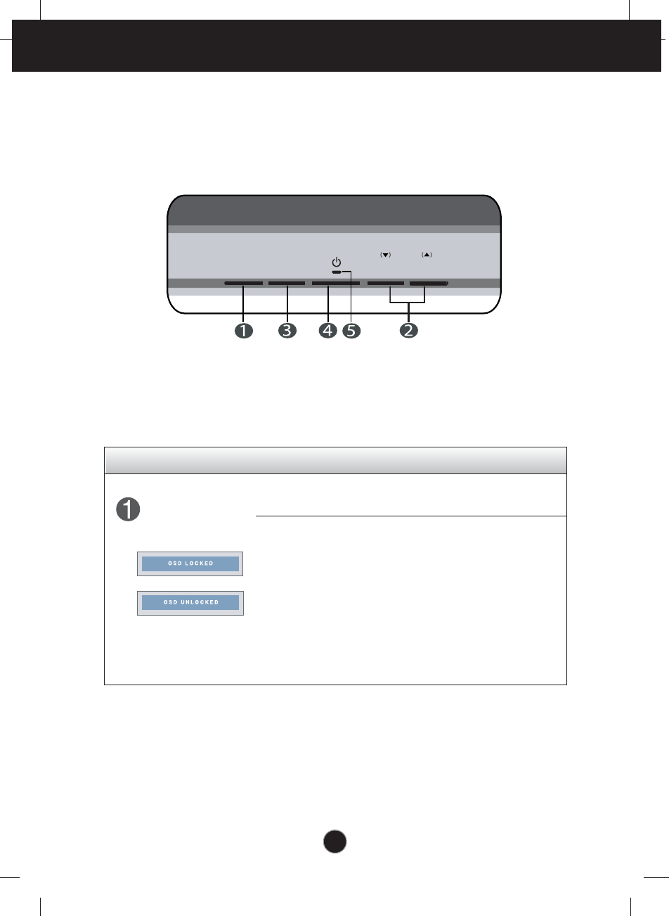
Control Panel Functions
M Button
se this button to enter or e it from the On Screen Display.
OSD OC D OC D
This function allows you to lock the current control settings, so
that these settings are not inadvertently changed. To lock the
OSD settings, press and hold the M button for several
seconds. The message OSD OC D appears.
You can unlock the OSD settings at any time by
pushing the M button for several seconds. The
message OSD OC D appears.
Front Panel Controls
MOTSOTAM SO RC
A1
Control Panel Functions
This Indicator lights up as blue when the display is
operating normally On ode . If the display is in
Sleep ode Energy Saving , this indicator changes
to flicker.
Use this button to turn the display on or off.
Power utton
Power Indicator
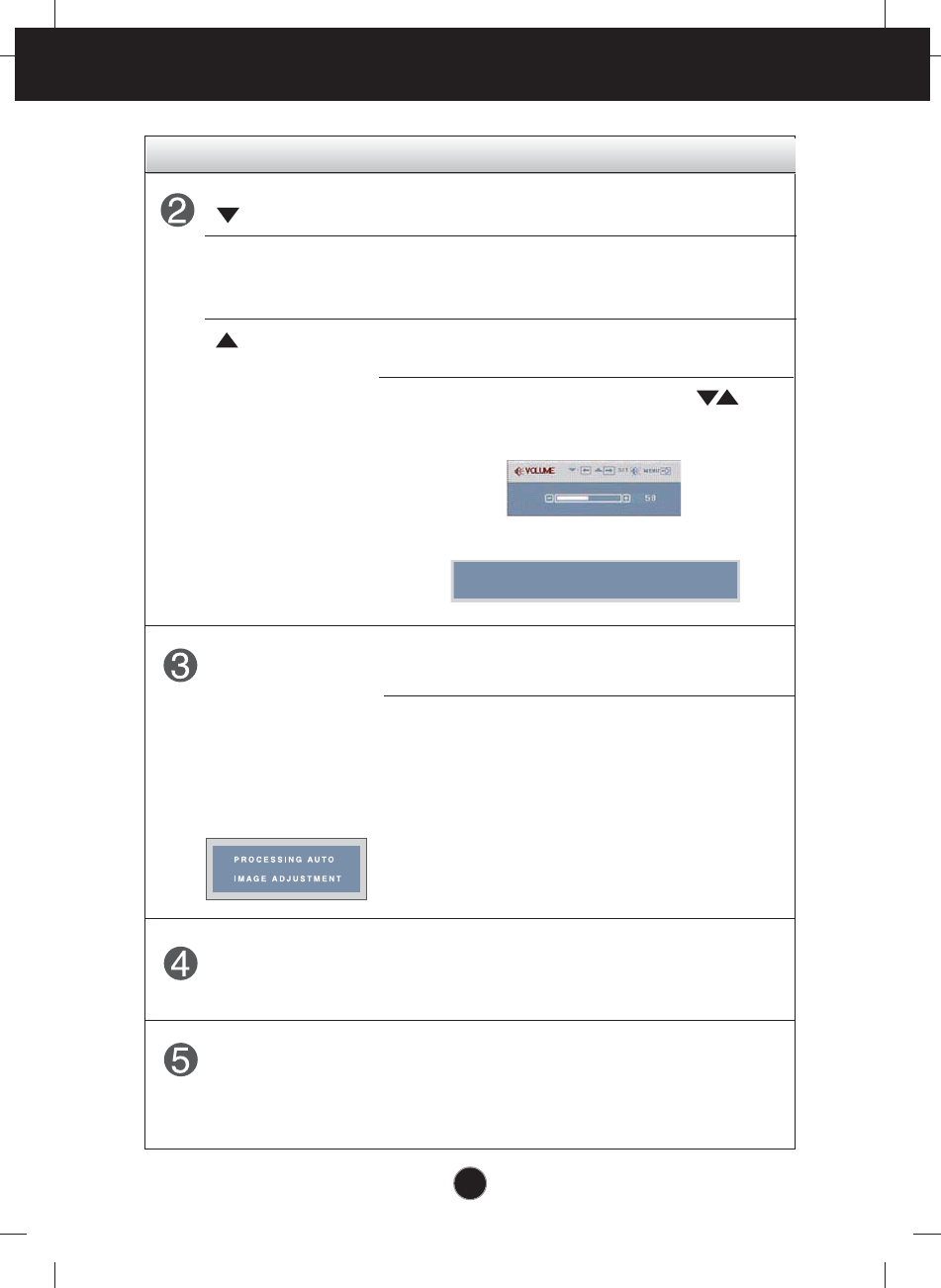
Use this button to select an icon in the On Screen
Display.
AUTO SET
utton
AUTO I A E AD UST ENT
When adjusting your display settings, always press
the AUTO SET button prior to entering the On
Screen Display OSD . This will automatically adjust
your display image to the ideal settings for the
current screen resolution size display mode .
The best display mode is:
N1 : 1 x1 D-sub 1 x -PO T
noitcnuF lortnoC
VO U E
Use these buttons to select or adjust functions in the
On Screen Display.
Use these buttons to select or adjust functions in the On
Screen Display.
SOU CE
Use this button to make either D-Sub or -PO T
connector active. This feature is used when two
input sources are connected to the display.
•D-sub : This menu is not available.
{opzGtlu|GpzGuv{Gh}hpshisl
•-PO T: When -PO T signal is active,use button
to decrease or increase the speaker volume on
-PO T input.
N1 : 1 x1 D-sub 1 x -PO T
A1
On Screen Display OSD Control Adjustment
Screen Adjustment
aking adjustments to the image size, position and operating parameters of
the display is uick and easy with the On Screen Display Control system.
A short example is given below to familiarize you with the use of the controls.
The following section is an outline of the available adjustments and selections
you can make using the OSD.
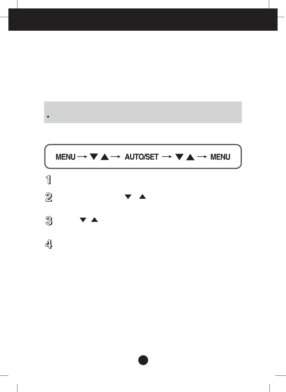
To make adjustments in the On Screen Display, follow these steps:
Press the ENU utton , then the main menu of the OSD appears.
To access a control, use the or uttons . When the icon you want
becomes highlighted, press the AUTO SET utton .
Use the uttons to adjust the image to the desired level. Use the
AUTO SET utton to select other sub-menu items.
Push the ENU utton once to return to the main menu to select another
function. Push the ENU utton twice to exit from the OSD.
NOTE
Allow the display to stabilize for at least minutes before making image adjustments.
A1
OT
The order of icons may differ depending on the model (A14 A1 ).
On Screen Display(OSD) Selection and Adjustment
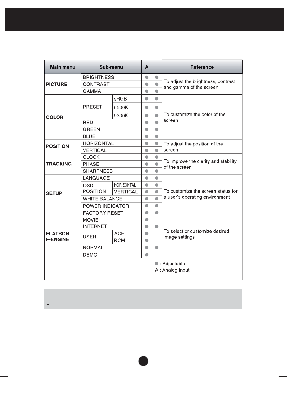
The following table indicates all the On Screen Display control, adjustment,
and setting menus.
X
PORT Input
Menu Name
A15
On Screen Display(OSD) Selection and Adjustment
NOTE
OSD (On Screen Display) menu languages on the monitor may differ from the manual.
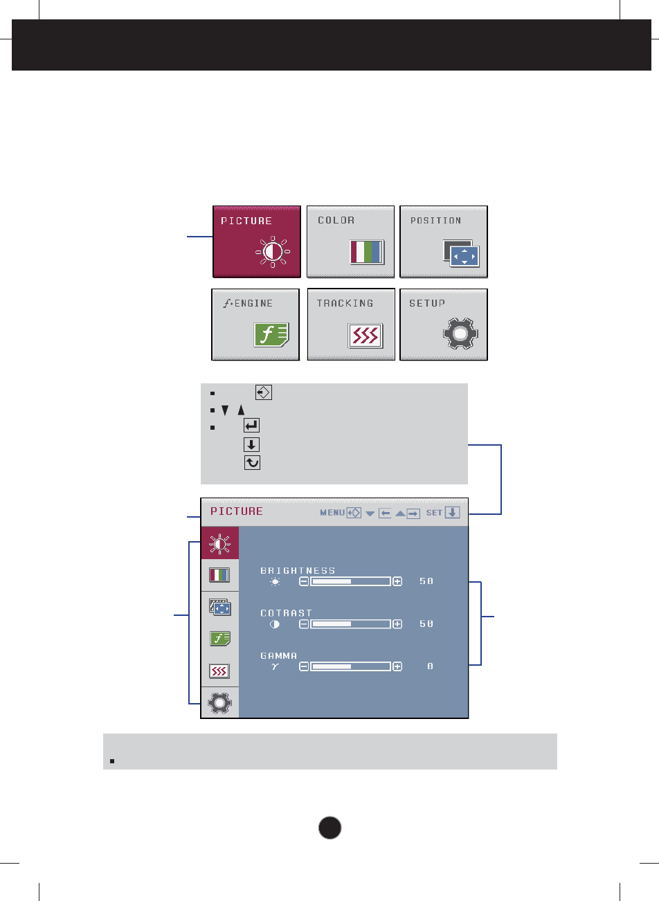
You were introduced to the procedure of selecting and adjusting an item
using the OSD system. Listed below are the icons, icon names, and icon
descriptions of the all items shown on the Menu.
Press the MENU Button, then the main menu of the OSD appears.
Menu Name
Main Menu
Button Tip
MENU : Exit
: Adjust (Decrease/Increase)
SET : Enter
: Select another sub-menu
: Restart to select sub-menu
Sub-menus
Icons
A1
On Screen Display OSD Selection and Adjustment
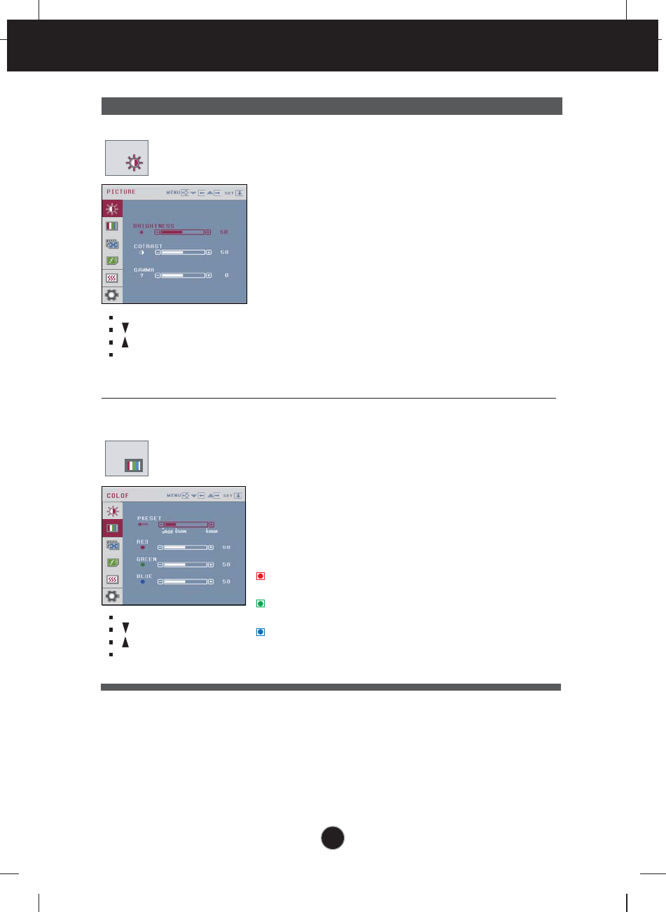
ain menu Sub menu Description
I HTNESS
CONT AST
AA
To adjust the brightness of the screen.
To adjust the contrast of the screen.
Set your own gamma value. : -
On the monitor, high gamma values
display whitish images and low gamma
values display high contrast images.
PICTU E
P ESET
ED
EEN
UE
• sRGB: Set the screen color to fit the
S standard color
specification.
• 6500K: Slightly reddish white.
• 9300K: Slightly bluish white.
Set your own red color levels.
Set your own green color levels.
Set your own blue color levels.
CO O
PICTU E
CO O
ENU : Exit
: Decrease
: Increase
SET : Select another sub-menu
ENU : Exit
: Decrease
: Increase
SET : Select another sub-menu
A17
On Screen Display(OSD) Selection and Adjustment
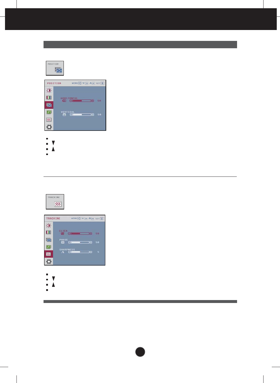
Main menu Sub menu Description
CLOCK
PHASE
SHARPNESS
To minimize any vertical bars or
stripes visible on the screen
background.
The horizontal screen size will also
change.
To adjust the focus of the display.
This item allows you to remove
any horizontal noise and clear or
sharpen the image of characters.
To adjust the clearness of the
screen.
POSITION
MENU : Exit
: Decrease
: Increase
SET : Select another sub-menu
HORIZONTAL
VERTICAL
To move image left and right.
To move image up and down.
MENU : Exit
: Decrease
: Increase
SET : Select another sub-menu
TRACKING
estore all factory default settings except
AN UA E .
Press the , buttons to reset immediately.
A1
On Screen Display(OSD) Selection and Adjustment
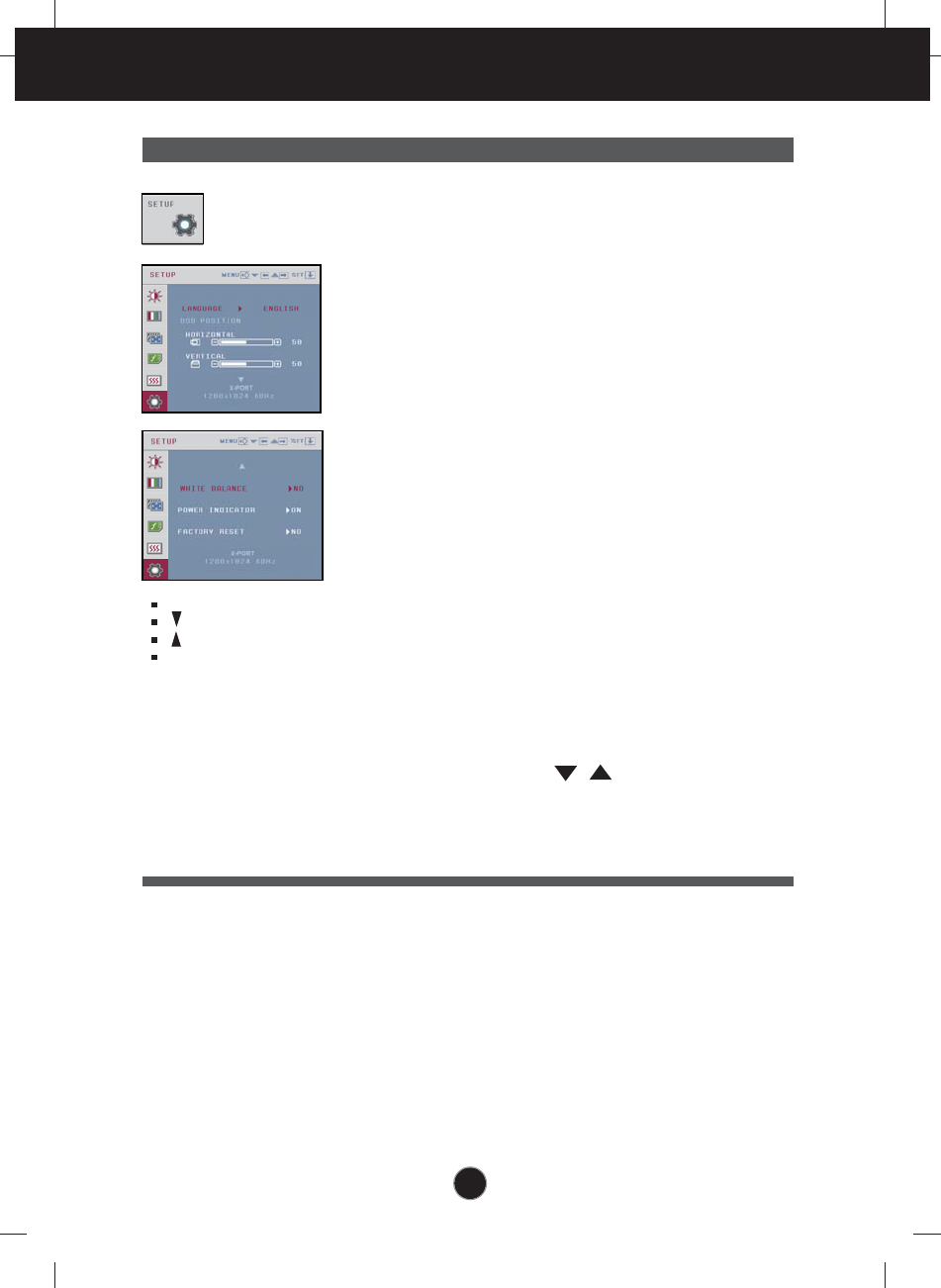
Main menu Sub menu Description
If this does not improve the screen image, restore the factory default settings.
If necessary, perform the white balance function again. This function will be enabled only when
the input signal is a D sub or PORT signal.
STP
To choose the language in which the
control names are displayed.
To adjust position of the OSD window
on the screen.
AA
OSD
POSITIO
HIT
BA A C
FACTORY
RST
If the output of the video card is different
from the re uired specifications, the color
level may deteriorate due to video
signal distortion. sing this function, the
signal level is adjusted to fit into the
standard output level of the video card
in order to provide the optimal image.
Activate this function when white and
black colors are present in the screen.
PO R
I DICATOR
se this function to set the power
indicator on the front side of the monitor
to O or OFF.
If you set OFF, it will go off.
If you set O at any time, the power
indicator will automatically be turned on.
M it
Adjust
Adjust
ST
Select another sub menu
A19
On Screen Display(OSD) Selection and Adjustment
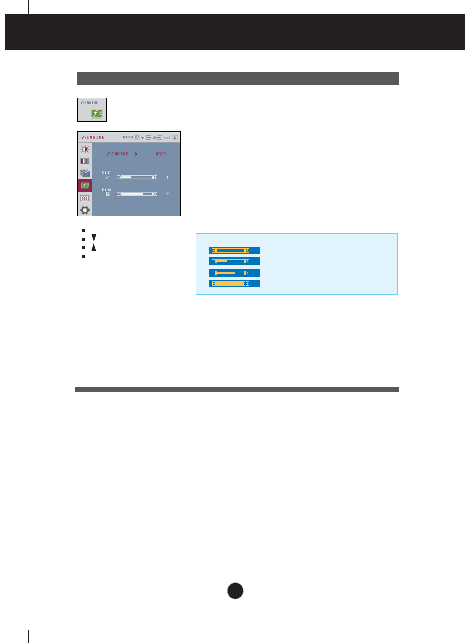
Main menu Sub menu Description
MOVIE
INTERNET
NORMAL
DEMO
USER
INTERNET
: For text images (Word processing etc.)
MOVIE
: For animation images in videos or movies
This is under normal operating conditions.
This is just for advertising to customer in the
shops. It’s setting is same with Movie mode and
screen is divided by half.
This feature lets you easily select the best desired
image condition optimized to the environment
(ambient illumination, image types etc).
User
You can manually adjust brightness, ACE or RCM.
You can save or restore the adjusted value even
when using a different environment.
...
ACE
(Adaptive Clarity Enhancer)
: Selects the clarity mode.
...
RCM(Real Color Management): Selects the color mode.
Not applied
Green enhance
Flesh tone
Color Enhance
0
1
2
3
F-ENGINE
MENU : Exit
: Decrease
: Increase
SET : Select another
sub-menu
The INTERNET and NORMAL features become enabled for X-PORT input.
A
Troubleshooting
No image appears
Check the following before calling for service.
No image appears
Do you see a OSD OCKED message on the screen
Is the power cord of the
display connected
Is the power indicator
light on
Is the power on and the
power indicator blue
Is the power indicator
flickering
Do you see an OUT OF
AN E message on
the screen
Do you see a CHECK
SI NA CA E
message on the
screen
•
Check and see if the power cord is connected
properly to the power outlet.
•
Press the Power button.
•
Adjust the brightness and the contrast.
•
If the display is in power saving mode, try moving
the mouse or pressing any key on the keyboard to
bring up the screen.
•Try to turn on the PC
.
•
This message appears when the signal from the
PC video card is out of horizontal or vertical
fre uency range of the display. See the
'Specifications' section of this manual and
configure your display again.
•
This message appears when the signal cable
between your PC and your display is not
connected. Check the signal cable and try again.
• ou can secure the current control settings,
so that they cannot be inadvertently changed.
ou can unlock the OSD controls at any time
by pushing the ENU button for several
seconds: the message
OSD UN OCKED will appear.
Do you see OSD
OCKED when you
push ENU button
A17A21
Troubleshooting
Display image is incorrect
Display Position is
incorrect.
On the screen
background, vertical
bars or stripes are
visible.
Any horizontal noise
appearing in any
image or characters
are not clearly
portrayed.
•
Press the AUTO/SET button to automatically
adjust your display image to the ideal setting.
If the results are unsatisfactory, adjust the image
position using the H position and V position icon
in the on screen display.
•
Press the AUTO/SET button to automatically
adjust your display image to the ideal setting.
If the results are unsatisfactory, decrease the
vertical bars or stripes using the CLOCK icon in
the on screen display.
•
Press the AUTO/SET button to automatically
adjust your display image to the ideal setting.
If the results are unsatisfactory, decrease the
horizontal bars using the PHASE icon in the on
screen display.
•
Check Control Panel --> Display --> Settings
and adjust the display to the recommended
resolution or adjust the display image to the ideal
setting. Set the color setting higher than 24 bits
(true color).(Only for RGB)
Important
Check Control Panel --> Display --> Settings and see if the frequency or the
resolution were changed. If yes, readjust the video card to the recommend
resolution.(Only for RGB)
The setting method can differ by computer and O/S (Operation System),
and resolution mentioned above may not be supported by the video card
performance. In this case, please ask to the computer or the video card
manufacturer.(Only for RGB)
A1A22
Troubleshooting
Display image is incorrect
The screen color is
mono or abnormal.
The screen blinks.
•
Check if the signal cable is properly connected
and use a screwdriver to fasten if necessary.
•
Make sure the video card is properly inserted in
the slot.
•
Set the color setting higher than 24 bits (true color)
at Control Panel Settings.
•
Check if the screen is set to interlace mode and if
yes, change it to the recommend resolution.
( PORT support only 1 bits color)
“ hite Balance” is performed on black white
pattern.
Check if the screen is set to normal mode.
Check if the screen is set to normal mode.
A19A23
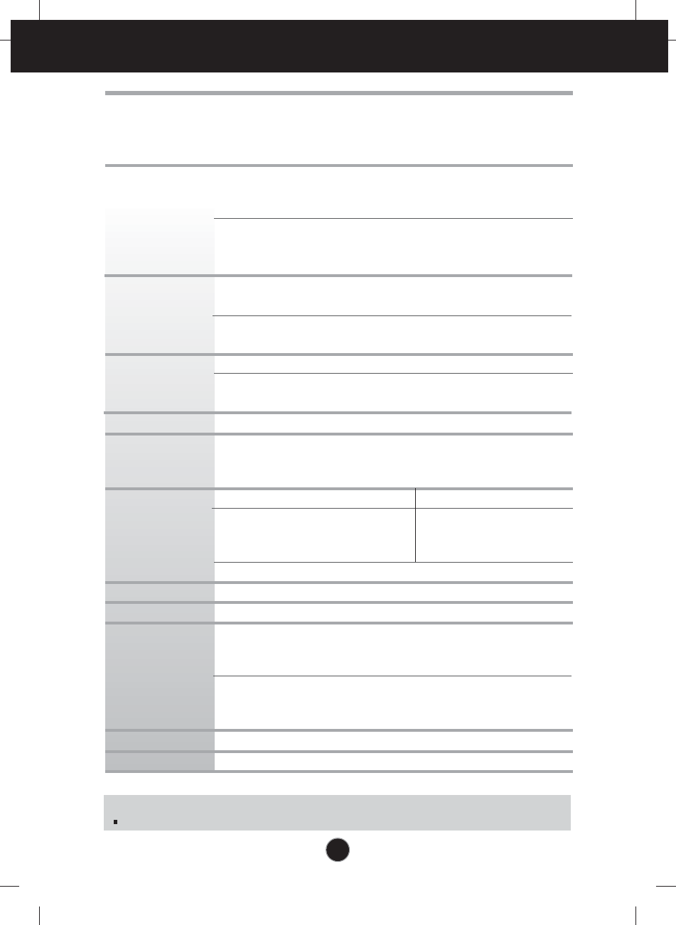
Specifications
Display
Sync Input
Video Input
Resolution
Plug&Play
Power
Consumption
Dimensions
&Weight
Tilt Range
Power Input
Environmental
Conditions
Stand Base
Power cord
NOTE
Information in this document is subject to change without notice.
17 inches (43.2 cm) Flat Panel Active matrix-TFT LCD
Anti-Glare coating
Visible diagonal size:
43.2
cm
0.264 mm pixel pitch
Horizontal Freq. 30 - 66 kHz (Automatic)
Vertical Freq. 57 - 63 Hz (Automatic)
1440 x 900 (60Hz)
Signal Input X-PORT Connector
Input Form X-PORT Signal
Max VESA 1280 x 1024 @60 Hz
VESA 1280 x 1024 @60 Hz
DDC 2B(Only for RGB)
0n Mode : 32 W(Typ.)
Sleep Mode ≤1 W
Off Mode ≤1 W
With Stand Without Stand
Width 36.96 cm / 14.55 inches 36.96 cm / 14.55 inches
Height 39.13 cm / 15.41 inches 31.51 cm / 12.41 inches
Depth 18.48 cm / 7.28 inches 5.90 cm / 2.32 inches
Net 3.1 kg ( 6.89 lbs)
Tilt -5˚~20˚
AC 100-240V~ 50/60Hz 0.8A
Operating Conditions
Temperature 10˚C to 35 ˚C
Humidity 10 % to 80 % non-Condensing
Storage Conditions
Temperature -20˚C to 60 ˚C
Humidity 5 % to 90 % non-Condensing
Attached( ), Detached ( O )
Wall-outlet type
N1742L
Signal Input 15 pin D-Sub Connector
Input Form RGB Analog (0.7 Vp-p/ 75 ohm)
RGB
X-PORT
RGB support 60Hz only(except Dos mode)
RGB
X-PORT 1280 x 1024 (60Hz)
1024 x 768 (60Hz)
1280 x 720 (60Hz)
800 x 600 (72Hz)
Recommend RGB
X-PORT VESA 1024 x 768 @60 Hz
A24
Specifications N1942L
NOTE
Information in this document is subject to change without notice.
Display
Sync Input
Video Input
Resolution
Plug&Play
Power
Consumption
Dimensions
&Weight
Tilt Range
Power Input
Environmental
Conditions
Stand Base
Power cord
19 inches (48.2 cm) Flat Panel Active matrix-TFT LCD
Anti-Glare coating
Visible diagonal size:
48.2
cm
0.294 mm pixel pitch
Horizontal Freq. 30 - 66 kHz (Automatic)
Vertical Freq. 57 - 63 Hz (Automatic)
Signal Input 15 pin D-Sub Connector
Input Form RGB Analog (0.7 Vp-p/ 75 ohm)
Max VESA 1280 x 1024 @60 Hz
Recommend
DDC 2B(Only for RGB)
0n Mode : 40 W(Max.)
Sleep Mode ≤1 W
Off Mode ≤1 W
With Stand Without Stand
Width 40.63 cm / 16.00 inches 40.63 cm / 16.00 inches
Height 41.97 cm / 16.52 inches 34.45 cm / 13.56 inches
Depth 18.48 cm / 7.28 inches 5.99 cm / 2.36 inches
Net 3.5 kg (7.78 lbs)
Tilt -5˚~20˚
AC 100-240V~ 50/60Hz 0.8A
Operating Conditions
Temperature 10˚C to 35 ˚C
Humidity 10 % to 80 % non-Condensing
Storage Conditions
Temperature -20˚C to 60 ˚C
Humidity 5 % to 90 % non-Condensing
Attached( ), Detached ( O )
Wall-outlet type
RGB support 60Hz only(except Dos mode)
RGB
Signal Input X-PORT Connector
Input Form X-PORT Signal
X-PORT
RGB
1440 x 900 (60Hz)
X-PORT 1280 x 1024 (60Hz)
1024 x 768 (60Hz)
1280 x 720 (60Hz)
800 x 600 (72Hz)
VESA 1280 x 1024 @60 HzRGB
X-PORT VESA 1024 x 768 @60 Hz

A25
Specifications
Display Modes (Resolution) Horizontal Freq. (kHz) Vertical Freq. (Hz)
1
2
3
4
5
*6
640 x 350
720 x 400
640 x 480
800 x 600
1024 x 768
1280 x 1024
31.469
31.468
31.469
37.879
48.363
63.981
70
70
60
60
60
60
Indicator
On Mode
Sleep Mode
Off Mode
blue
flicker
Off
LED Color
MODE
RGB Preset Modes (Resolution)
* Recommend Mode
Display Modes (Resolution)
1
*2
3
4
5
800 x 600 (72Hz)
1024 x 768 (60Hz)
1280 x 720 (60Hz)
1280 x 1024 (60Hz)
X-PORT Preset Modes (Resolution)
* Recommend Mode
1440 x 900 (60Hz)
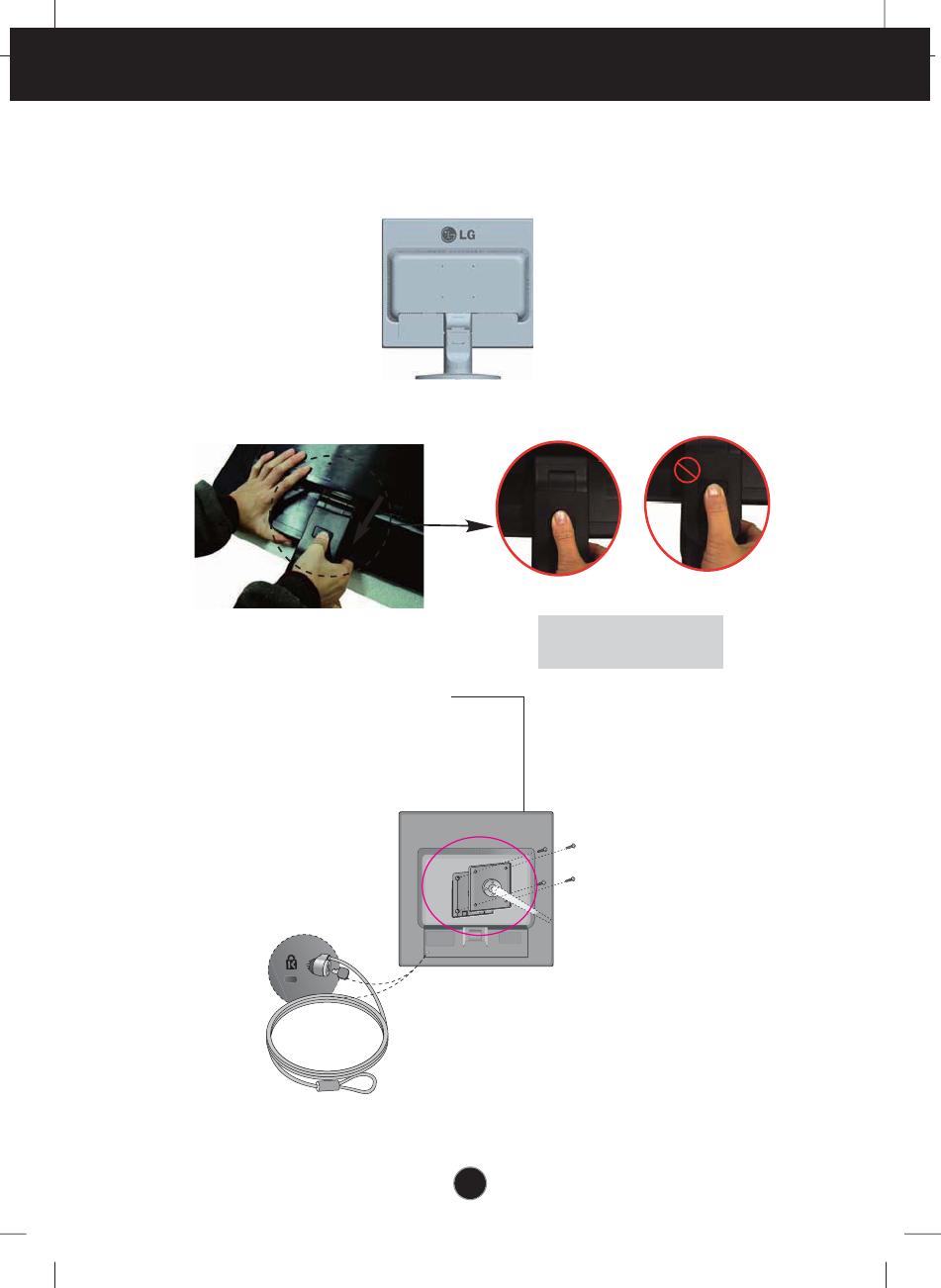
A
Installing the all mount plate
all mount plate(Separate purchase)
This is stand type or wall mount type and is
connectable with all mount plate.
Please refer to the installation guide for more
details, which is provided when all mount
plate is purchased.
ensington Security Slot
Connected to a locking cable that can be
purchased separately at most computer stores.
This monitor satisfies the specifications of the all mount plate or
the interchange device.
1. Place the monitor with its front facing downward on a soft cloth.
2.Separate the stand by pushing the P SH button.
3.
Install the all mount plate.
arning
You can hurt your finger.
ood Position Bad Position

Digitally yours